EP4411270A1 - Drain pan and air conditioner - Google Patents
Drain pan and air conditioner Download PDFInfo
- Publication number
- EP4411270A1 EP4411270A1 EP22874262.3A EP22874262A EP4411270A1 EP 4411270 A1 EP4411270 A1 EP 4411270A1 EP 22874262 A EP22874262 A EP 22874262A EP 4411270 A1 EP4411270 A1 EP 4411270A1
- Authority
- EP
- European Patent Office
- Prior art keywords
- water pan
- air outlet
- plastic member
- air
- grille
- Prior art date
- Legal status (The legal status is an assumption and is not a legal conclusion. Google has not performed a legal analysis and makes no representation as to the accuracy of the status listed.)
- Pending
Links
- XLYOFNOQVPJJNP-UHFFFAOYSA-N water Substances O XLYOFNOQVPJJNP-UHFFFAOYSA-N 0.000 claims abstract description 112
- 238000005187 foaming Methods 0.000 claims abstract description 64
- 230000001681 protective effect Effects 0.000 claims description 17
- 239000006261 foam material Substances 0.000 claims description 16
- 230000002093 peripheral effect Effects 0.000 claims description 16
- 238000001746 injection moulding Methods 0.000 claims description 8
- 230000007423 decrease Effects 0.000 claims description 5
- 238000002347 injection Methods 0.000 claims description 5
- 239000007924 injection Substances 0.000 claims description 5
- 238000005266 casting Methods 0.000 claims description 4
- 230000000694 effects Effects 0.000 abstract description 11
- 238000004519 manufacturing process Methods 0.000 abstract description 11
- 239000003351 stiffener Substances 0.000 description 25
- 238000009434 installation Methods 0.000 description 13
- 239000000463 material Substances 0.000 description 10
- 238000012423 maintenance Methods 0.000 description 6
- 238000000034 method Methods 0.000 description 4
- 230000002708 enhancing effect Effects 0.000 description 3
- 230000006872 improvement Effects 0.000 description 3
- 238000004321 preservation Methods 0.000 description 3
- 230000008569 process Effects 0.000 description 3
- 238000005452 bending Methods 0.000 description 2
- 230000009286 beneficial effect Effects 0.000 description 2
- 239000006260 foam Substances 0.000 description 2
- 230000001965 increasing effect Effects 0.000 description 2
- 238000012545 processing Methods 0.000 description 2
- 238000004378 air conditioning Methods 0.000 description 1
- 230000004888 barrier function Effects 0.000 description 1
- 230000000903 blocking effect Effects 0.000 description 1
- 238000004891 communication Methods 0.000 description 1
- 238000009833 condensation Methods 0.000 description 1
- 238000001816 cooling Methods 0.000 description 1
- 238000013461 design Methods 0.000 description 1
- 238000011161 development Methods 0.000 description 1
- 238000009826 distribution Methods 0.000 description 1
- 238000001914 filtration Methods 0.000 description 1
- 238000003780 insertion Methods 0.000 description 1
- 230000037431 insertion Effects 0.000 description 1
- 230000003993 interaction Effects 0.000 description 1
- 239000002184 metal Substances 0.000 description 1
- 238000012986 modification Methods 0.000 description 1
- 230000004048 modification Effects 0.000 description 1
- 239000000243 solution Substances 0.000 description 1
- 229910001220 stainless steel Inorganic materials 0.000 description 1
- 239000010935 stainless steel Substances 0.000 description 1
- 238000005728 strengthening Methods 0.000 description 1
- 238000012360 testing method Methods 0.000 description 1
- 238000012546 transfer Methods 0.000 description 1
- 238000009423 ventilation Methods 0.000 description 1
Images



Classifications
-
- F—MECHANICAL ENGINEERING; LIGHTING; HEATING; WEAPONS; BLASTING
- F24—HEATING; RANGES; VENTILATING
- F24F—AIR-CONDITIONING; AIR-HUMIDIFICATION; VENTILATION; USE OF AIR CURRENTS FOR SCREENING
- F24F13/00—Details common to, or for air-conditioning, air-humidification, ventilation or use of air currents for screening
- F24F13/22—Means for preventing condensation or evacuating condensate
-
- F—MECHANICAL ENGINEERING; LIGHTING; HEATING; WEAPONS; BLASTING
- F24—HEATING; RANGES; VENTILATING
- F24F—AIR-CONDITIONING; AIR-HUMIDIFICATION; VENTILATION; USE OF AIR CURRENTS FOR SCREENING
- F24F13/00—Details common to, or for air-conditioning, air-humidification, ventilation or use of air currents for screening
- F24F13/22—Means for preventing condensation or evacuating condensate
- F24F13/222—Means for preventing condensation or evacuating condensate for evacuating condensate
-
- F—MECHANICAL ENGINEERING; LIGHTING; HEATING; WEAPONS; BLASTING
- F24—HEATING; RANGES; VENTILATING
- F24F—AIR-CONDITIONING; AIR-HUMIDIFICATION; VENTILATION; USE OF AIR CURRENTS FOR SCREENING
- F24F1/00—Room units for air-conditioning, e.g. separate or self-contained units or units receiving primary air from a central station
- F24F1/0007—Indoor units, e.g. fan coil units
- F24F1/0011—Indoor units, e.g. fan coil units characterised by air outlets
-
- F—MECHANICAL ENGINEERING; LIGHTING; HEATING; WEAPONS; BLASTING
- F24—HEATING; RANGES; VENTILATING
- F24F—AIR-CONDITIONING; AIR-HUMIDIFICATION; VENTILATION; USE OF AIR CURRENTS FOR SCREENING
- F24F11/00—Control or safety arrangements
- F24F11/89—Arrangement or mounting of control or safety devices
-
- F—MECHANICAL ENGINEERING; LIGHTING; HEATING; WEAPONS; BLASTING
- F24—HEATING; RANGES; VENTILATING
- F24F—AIR-CONDITIONING; AIR-HUMIDIFICATION; VENTILATION; USE OF AIR CURRENTS FOR SCREENING
- F24F13/00—Details common to, or for air-conditioning, air-humidification, ventilation or use of air currents for screening
- F24F13/08—Air-flow control members, e.g. louvres, grilles, flaps or guide plates
- F24F13/082—Grilles, registers or guards
-
- F—MECHANICAL ENGINEERING; LIGHTING; HEATING; WEAPONS; BLASTING
- F24—HEATING; RANGES; VENTILATING
- F24F—AIR-CONDITIONING; AIR-HUMIDIFICATION; VENTILATION; USE OF AIR CURRENTS FOR SCREENING
- F24F8/00—Treatment, e.g. purification, of air supplied to human living or working spaces otherwise than by heating, cooling, humidifying or drying
- F24F8/30—Treatment, e.g. purification, of air supplied to human living or working spaces otherwise than by heating, cooling, humidifying or drying by ionisation
-
- F—MECHANICAL ENGINEERING; LIGHTING; HEATING; WEAPONS; BLASTING
- F24—HEATING; RANGES; VENTILATING
- F24F—AIR-CONDITIONING; AIR-HUMIDIFICATION; VENTILATION; USE OF AIR CURRENTS FOR SCREENING
- F24F1/00—Room units for air-conditioning, e.g. separate or self-contained units or units receiving primary air from a central station
- F24F1/0007—Indoor units, e.g. fan coil units
- F24F1/0043—Indoor units, e.g. fan coil units characterised by mounting arrangements
- F24F1/0047—Indoor units, e.g. fan coil units characterised by mounting arrangements mounted in the ceiling or at the ceiling
-
- F—MECHANICAL ENGINEERING; LIGHTING; HEATING; WEAPONS; BLASTING
- F24—HEATING; RANGES; VENTILATING
- F24F—AIR-CONDITIONING; AIR-HUMIDIFICATION; VENTILATION; USE OF AIR CURRENTS FOR SCREENING
- F24F2110/00—Control inputs relating to air properties
- F24F2110/10—Temperature
Definitions
- the present application relates to the field of air conditioner manufacturing, and more particularly to a water pan and an air conditioner.
- Air conditioner products are developing in the direction of compact structure and efficient performance.
- a size of an air outlet of the air conditioners affects the overall air volume and heat exchange efficiency of the air conditioners.
- a plurality of small air outlets is usually provided, and the circulation area of each air outlet is small, so the overall air volume is difficult to be improved.
- the air outlet problem of the air conditioners has become a barrier to be solved urgently under the trend of efficient-performance development. Moreover, in related art, it is the difficult to increase the air outlet area of a water pan due to the limitations of its structure and the production process.
- a water pan including:
- the water pan of embodiments of the present application has the following technical effect: the air outlet is arranged into a continuously extended structure, a circulation area of the air outlet is increased, thus improving air outlet efficiency, and facilitating the improvement of the performance of the air conditioner.
- the foaming member and the plastic member are integrally formed.
- the supporting grille is arranged along a direction from the air inlet to the air outlet.
- an air inlet avoidance hole is defined in a middle of the foaming member, an air outlet avoidance hole is defined between a second frame and the water receiving sink, the air inlet avoidance hole corresponds in position to the air inlet, and the air outlet avoidance hole corresponds in position to the air outlet.
- the plastic member has a first frame, end of the supporting grille has a first end connected to the first frame, and a second end connected to the middle of the plastic member; and the first frame is connected with the second frame.
- a cross-section of the supporting grille gradually decreases along an air outlet direction.
- a width of the supporting grille ranges from 1.5 mm to 3.2 mm.
- the foaming member are integrally formed with the plastic member by injection molding the plastic member, and directly casting a foam material on the plastic member with a mold after the formed plastic member is solidified, so that the foam material and the plastic member are at least partially melted together, and the foam material is connected with the plastic member after the foam material is solidified.
- the water receiving sink is a square ring structure; the air outlet surrounds four outer sides of the water receiving sink, and each outer side is connected to at least one supporting grille.
- the plastic member has a plurality of connecting parts, and the connecting part penetrates the foaming member.
- an air guiding ring is formed in the middle of the plastic member, the air inlet is defined in a center of the air guiding ring, and the air guiding ring and the foaming member do not overlap.
- the air inlet is covered with a protective net, and the protective net is detachably connected to the foaming member or the plastic member.
- the foaming member is provided with a negative ion generator mounting part configured to mount a negative ion generator and a temperature sensor mounting part configured to mount a temperature sensor, and the negative ion generator mounting part is located on a side of the temperature sensor mounting part.
- the foaming member is provided with a wire slot, the wire slot is close to the air outlet and configured for pass through of connecting wires of the negative ion generator and the temperature sensor.
- the protective net is a grille
- the grille includes a body, the body is adapted to be connected with the water pan, the body is provided with a plurality of first buttons, and the first button is adapted to be snap-fitted with the water pan to connect the body and the water pan.
- the grille further includes a mounting part, the mounting part is located on an outer peripheral side of the body, and the mounting part is adapted to mount the temperature sensor and/or the negative ion generator.
- the body and the mounting part are integrally injection molded.
- a protrusion is provided on the mounting part, the protrusion includes a first segment and a second segment, the first segment has a convex surface and a concave surface arranged opposite each other, the convex surface is adapted to abut against the negative ion generator to limit the negative ion generator, the second segment is arranged on a side of the concave surface of the first segment, and the second segment is connected with the concave surface.
- the mounting part and/or the body are provided with a first wire clip and a second wire clip, the first wire clip is adapted to clamp a wire of the temperature sensor, and the second wire clip is adapted to clamp a wire of the negative ion generator.
- Embodiments of the present application also provide an air conditioner, including a water pan according to any one of embodiments of the present application.
- the installation of the water pan of the air conditioner is convenient, so that the production efficiency of the air conditioner is improved.
- the width of the support grating is small, the air output effect is good, and the user experience is improved.
- Embodiments of the present application provide a water pan, the water pan is used for an air conditioner, which may improve the efficiency of air inlet and air outlet, has high overall structural stability, and may improve the convenience and accuracy of installation on an air conditioner.
- the air conditioner may be a central air conditioner, and the water pan may be installed on an indoor air inlet and outlet device of the central air conditioner.
- the water pan of embodiments of the present application mainly includes two parts of a plastic member 10 and a foaming member 20, and the two parts are connected as a whole and do not need to be connected by a screw and other connectors.
- the materials of the plastic member 10 and the foaming member 20 are different, they have an integrally formed structure, and there is no need to assemble separately when in use, thus improving the convenience of installation, improving production efficiency, and further facilitating improvement of the accuracy of the relative position between the air inlet 11 and a related component of the air conditioner.
- an air inlet 11 is defined in a middle of the plastic member 10
- an air outlet 12 is defined near an edge of the plastic member 10
- a water receiving sink 17 is defined between the air inlet 11 and the air outlet 12.
- the water receiving sink 17 surrounds the air inlet 11, and the air outlet 12 continuously surrounds at least part of an outer edge of the water receiving sink 17.
- a plurality of supporting grilles 14 is arranged in the air outlet 12, and the plurality of supporting grilles 14 is distributed at intervals along an extension direction of the air outlet 12. In embodiments of the present application, only one air outlet 12 is provided, and continuously surrounds the water receiving sink 17, to form an annular air outlet, thus increasing the circulation area of the air outlet 12.
- the water receiving sink 17 is arranged as a long strip shape and extends along a predetermined direction to contain the condensate water and transfer the collected condensate water to a preset pipe. In some embodiments, the water receiving sink 17 is a continuous recess, and the condensate water may flow within the water receiving sink 17.
- the supporting grille 14 is a plate-like body, and a thickness of the supporting grille 14 gradually decreases along an air outlet direction. That is, a width of a cross-section of the supporting grille 14 at different locations may be different. The setting may not only reduce wind resistance, but also has the effect of reducing noise.
- the water pan is made of foam, and the strength of foam is low, so at the air outlet, a long connection structure needs to be provided to connect a frame, which will cause a larger area of blocking to the air outlet.
- the foaming member 20 is integrally formed with the plastic member 10.
- the water pan is made by foaming a foam material on the plastic member, the strength of the plastic member is high, the strength of the water pan formed by the process is high, and the section of the supporting grille 14 for connecting a first frame 16 at the air outlet may be made very small.
- the proportion of the wind shield area of the supporting grille 14 in the air outlet to the total area of the air outlet is very small, which may even be ignored, so that the annular air outlet may be achieved.
- the air outlet 12 is a bent long-strip hole with a certain length, and the width of the air outlet 12 may be set according to the actual design requirements.
- the supporting grille 14 plays the role of supporting and connection, which may be made as thin as possible under the premise of meeting the structural strength requirements, to reduce wind resistance.
- the foaming member 20 and the plastic member 10 at least partially overlap with each other, which play a role of heat preservation, so that the water pan achieves the effect of anti-condensation.
- the foaming member 20 avoids the air inlet 11 and the air outlet 12.
- the foaming member 20 is connected with the plastic member 10 and is relatively fixed.
- the foaming member 20 is integrally formed with the plastic member 10, the foaming member 20 defines the water receiving sink 17, the water receiving sink 17 surrounds the air inlet 11, and the air outlet 12 surrounds the water receiving sink 17. Since the foaming member 20 and the plastic members 10 are integrally formed, the foaming member 20 and the plastic members 10 also do not need to be assembled separately.
- the materials of the foaming member 20 and the plastic members 10 are different, they may be formed by injection molding. Therefore, the foaming member 20 and the plastic members 10 may be casted respectively by controlling the casting sequence of different materials, and the foaming member 20 and the plastic member 10 are connected as a whole.
- an air inlet avoidance hole 23 is defined in a middle of the foaming member 20, and an air outlet avoidance hole 24 is defined between a second frame 25 and the water receiving sink 17.
- the air inlet avoidance hole 23 corresponds in position to the air inlet 11, and the air outlet avoidance hole 24 corresponds in position to the air outlet 12.
- the air inlet avoidance hole 23 is a circular shape matching the air inlet 11, and the air outlet avoidance hole 24 is a bent long strip-shaped hole matching the shape of the air outlet 12.
- the supporting grille 14 is arranged along a direction from the air inlet 11 to the air outlet 12, and a width of the supporting grille 14 ranges from 1.5 mm to 3.2 mm. Since the plastic member 10 is made entirely of plastic material, the width of the supporting grille 14 that is available for mold-opening may be controlled above 1.5 mm. According to the test and the needs of the structural strength of the water pan, in embodiments of the present application, the width of the supporting grille 14 is limited to 3.2 mm. Thus, the width of the supporting grille 14 may be 1.6 mm, 1.8 mm, 2.0 mm, 2.2 mm, 2.4 mm, 2.6 mm, 2.8 mm, 3.0 mm, etc.
- the supporting grille 14 of the size not only has sufficient structural strength, but also causes very small wind resistance to the air outlet 12, which realizes a larger air outlet area and improves air outlet efficiency.
- the width of the supporting grille 14 mentioned here refers to the thickness of the cross-section of the supporting grille 14 occupying the air outlet 12, that is, a distance between the two sides of the supporting grille 14 in FIG. 3 .
- the supporting grille 14 is a plate-like body, where the width of the supporting grille 14 is the maximum thickness of the plate-like body.
- the plastic member 10 mainly plays the role of structural support for the whole water pan
- the foaming member 20 mainly plays the role of heat preservation for the whole water pan. If the foaming member 20 is provided with the supporting grille, because of the nature of the material itself, it is difficult to control the width of the supporting grille between 1.5 mm and 3.2 mm, and in the related art, in the solution of the foaming member 20 provided with the supporting grille, the width of the provided supporting grille is usually about 10 mm, thus the wind resistance to the air outlet 12 is larger.
- the foaming member 20 and the plastic member 10 are integrally formed, and the integral forming of the plastic member 10 and the foaming member 20 may eliminate the assembly error and improve the fit clearance between an air guiding ring and a fan wheel of the air conditioner.
- the integral forming means that the two are casted together during injection molding, so that the assembly step may be saved, the fit accuracy of the foaming member 20 and the plastic member 10 is good, and the individual difference of the water pan is small.
- the process method of the integral forming of the foaming member 20 and the plastic member 10 includes injection molding the plastic member 10, and directly casting a foam material on the plastic member 10 with a mold after the formed plastic member 10 is solidified, so that the foam material and the plastic member 10 are at least partially melted together, and the foam material is connected with the plastic member 10 after the foam material is solidified.
- the structural strength of the plastic member 10 is greater than that of the foaming member 20. Therefore, the plastic member 10 is first injected molded, and the foam material is injected after the plastic member 10 is solidified to form the foaming member 20 on the plastic member 10.
- the plastic member 10 and the foaming member 20 are at least partially melted together, so that the plastic member 10 and the foaming member 20 form an integrally formed structure. Therefore, the plastic member 10 and the foaming member 20 are inseparable two parts, and they do not have to be installed separately during the production of the air conditioner, thus the relative position of the plastic member 10 and the foaming member 20 is very accurate, and no assembly errors will be generated.
- the surface of the plastic member 10 in contact with it may be partially melted, to fuse with the foam material into a whole.
- the part of the plastic member 10 in contact with the foaming member 20 may also not melt with each other.
- the width of the supporting grille 14 ranges from 2 mm to 3 mm, for example from 2 mm to 2.5 mm.
- the size of the supporting grille 14 not only has sufficient structural strength, but also causes very small wind resistance to the air outlet 12, which realizes a larger air outlet area and improves air outlet efficiency.
- the plastic member 10 has a first frame 16, the supporting grille 14 has a first end connected to the first frame 16, and a second end connected to the middle of the plastic member 10.
- the first frame 16 is connected with the second frame 25, the first frame 16 plays a supporting role, and the second frame 25 plays a heat preservation role.
- a cross-section of the supporting grille 14 gradually decreases along the air outlet direction, that is, the width of the cross-section of the supporting grille 14 at different locations may not be equal.
- the setting further reduces wind resistance and has the effect of reducing noise.
- the directions of the arrows in FIG. 1 and FIG. 5 are the directions of air outlet and air inlet.
- the supporting grille 14 is a plate-like body, and the maximum width of the cross-section of the supporting grille 14 ranges from 1.5 mm to 3.2 mm.
- the shape of the air inlet 11 is circular and the shape of the water receiving sink 17 is square shaped. The four corners of the water receiving sink 17 are filleted, and the size of the air inlet 11 is matched with the size of the fan wheel of the air conditioner.
- the shape of the air inlet 11 is circular, and the inner diameter of the air inlet 11 gradually decreases along the direction of air inlet (from bottom to top). The structure is beneficial to improving the effect of air inlet and reducing the noise of air inlet.
- the directions of the arrows in the FIG. 5 are the directions of air inlet and air outlet.
- the air outlet 12 surrounds the four outer sides of the water receiving sink 17, and each outer side is connected to at least one supporting grille 14.
- the setting ensures the stability of the overall structure of the water pan.
- the air outlet 12 has three bent positions, and two supporting grilles 14 are provided at each bent position.
- a plane where the supporting grille 14 is located coincides with a center of the air inlet 11.
- the plastic member 10 has a plurality of connecting parts 13, and the connecting part 13 penetrates the foaming member 20.
- the connecting part 13 may be used to connect the water pan to other components of the air conditioner, and the structural stability of the integral forming of the plastic member 10 and the foaming member 20 may be improved by arranging the connecting part 13 to penetrate the foaming member 20.
- the connecting part 13 may be a cylindrical structure, and a center of the connecting part 13 may be provided with a threaded hole, thus the other components of the air conditioning unit may be installed with a water pan through the threaded hole.
- an air guiding ring 15 is formed in the middle of the plastic member 10, the air inlet 11 is defined in a center of the air guiding ring 15, and the air guiding ring 15 and the foaming member 20 do not overlap.
- the plastic member 10 is an integral structure, and the air guiding ring 15 is a part of the plastic member 10. Therefore, the water pan of embodiments of the present application does not have to install an independent air guiding ring component when in use. In other words, the water pan of embodiments of the present application has the structure of the air guiding ring, and such arrangement makes the fit between the air guiding ring 15 and the fan wheel of the air conditioner more accurate. Since it is not necessary to install the air guiding ring component separately, the production efficiency of the air conditioner is also improved.
- an inner surface of the air guiding ring 15 is a circular arc surface or a conical surface.
- the structure is beneficial to improving air inlet effect of the air inlet 11 and further reducing air inlet noise.
- the shape of the cross-section of the air guiding ring 15 may be a structure of 1/4 circular arc.
- the air inlet 11 is covered with a protective net 30, and the protective net 30 is detachably connected to the foaming member 20 or the plastic member 10.
- the protective net 30 may play a protective role, and the protective net 30 may be made of stainless steel.
- the protective net 30 may be connected with the plastic member 10 by a screw or by a snap.
- the protective net 30 may be a grille 30.
- the foaming member 20 is provided with a negative ion generator mounting part configured to mount a negative ion generator 1 and a temperature sensor mounting part configured to mount a temperature sensor 2, and the negative ion generator mounting part is located on a side of the temperature sensor mounting part.
- Afloat may also be arranged on the foaming member 20. Since the water pan takes into account the fixed assembly of the float, the negative ion generator 1 and the temperature sensor 2, and has a corresponding structure to take into account the wire routing and fixation, without too much irrelevant structure, the overall volume is small and the material utilization is high in the premise of ensuring the structural strength.
- the negative ion generator 1 and the temperature sensor 2 are arranged at an edge of the air inlet 11, so that the temperature sensor 2 may detect the temperature, and the negative ion generator 1 may purify the air, conveniently.
- the foaming member 20 defines a wire slot 22, and the connecting wire of electronic devices such as the negative ion generator 1, the temperature sensor 2 and the like may pass through the wire slot 22.
- the number of wire slot 22 is two, and the two wire slots 22 are respectively close to two extension ends of the air outlet 12, so that the air outlet 12 is a non-closed annular structure.
- Embodiments of the present application further provide an air conditioner, and the air conditioner includes a water pan of any one of the embodiments.
- the installation of the water pan of the air conditioner is convenient, so that the production efficiency of the air conditioner is improved, and the width of the supporting grille 14 is small, thus air outlet effect is good, and the user experience is improved.
- the grille 30 includes a body 31, and the body 31 is adapted to be connected with the water pan.
- the body 31 of the grille 30 may play the role of filtration and ventilation.
- the body 31 may be fixed to the water pan by a plurality of screws.
- the body 31 is provided with a plurality of first buttons 311, and the first button 311 is adapted to be snap-fitted with the water pan to connect the body 31 and the water pan 40. Since the grille 30 and the water pan 40 are snap-fitted, the installation and disassembly of the grille 30 and the water pan 40 are convenient, and then the overhaul and maintenance are convenient.
- the situation that in the related art a panel may be installed and fixed with the help of manpower to lift the panel is avoided, which reduces the labor load and labor cost of workers, facilitates the alignment of the panel, and improves the installation efficiency.
- the situation that in the related art pre-embedded sheet metal parts on the water pan are easy to cause too many parts below the water pan and the production efficiency of the water pan is low is also avoided.
- the body 31 may be circular, and it is understood that the body 31 may also be square, star, oval, and other shapes.
- the first button 311 may be a snap.
- a plurality of first buttons 311 may be arranged at intervals along a circumferential direction of the body 31, and when the grille 30 is installed, the plurality of first buttons 311 and the water pan may be clamped and fixed.
- the plurality of first buttons 311 is arranged at intervals along the circumferential direction of the body 1, and the plurality of first buttons 311 is adapted to be snapped with or separated from the water pan when the body 31 rotates with respect to the water pan.
- the first button 311 may also be a rotary button, and the plurality of first buttons 311 are located at an edge of the body 31 and are arranged at equal intervals along the circumferential direction of the body 31.
- the grille 30 may be rotated, and during rotation, the plurality of first buttons 311 on the body 31 may be clamped with the water pan 40, so that the installation and fixing of the grille 30 and the water pan 40 may be realized.
- the grille 30 may be reversely rotated. Thus, the installation and disassembly of the grille 30 are further facilitated.
- the body 31 is provided with a first hole 312, the first hole 312 is adapted for insertion of a first fastener, and the body 31 is detachably connected to the water pan 40 by the first fastener.
- the first hole 312 may be located at the edge of the body 31, the first fastener may be a bolt or a screw, and when the grille 30 and the water pan 40 are rotationally clamped or snap-fitted, the grille 30 and the water pan 40 may be connected and fixed by the first fastener, thus limiting the rotation of the grille 30, and avoiding the situation that the grille 30 is loosened and drops out due to rotate.
- the first fastener may be a bolt or a screw
- Only one first fastener may be provided, and the disassembly of the grille 30 may be achieved by disassembling the first fastener and then unlocking each first button 311, thus avoiding the situation that a plurality of screws needs to be disassembled in the related art, improving the installation and disassembly efficiency of the grille 30, and facilitating the overhaul and maintenance.
- the body 31 is provided with a stiffener 314 which is arranged between adjacent two first buttons 311 and extends along the circumferential direction of the body 31.
- the stiffener 314 may be located at an outer peripheral edge of the body 31, the stiffener 314 may bend and extend in the circumferential direction of the body 31, one end of the stiffener 314 may be connected with one of the adjacent two first buttons 311, and the other end of the stiffener 314 may be connected with the other of the adjacent two first buttons 311, thus enhancing the structural strength of the body 31, and ensuring the structural stability of the shape of the body 31.
- the stiffener 314 and the body 31 is integrally injection molded.
- the material of the body 31 is plastic.
- the plastic material facilitates the injection molding of the grille 30, and since the body 31 is provided with stiffener, the grille 30 still has high structural strength, avoiding the situation that the shape of the body 31 is easy to deform when the plastic is adopted.
- the stiffener 314 is plural, and the plurality of stiffeners 314 and the plurality of first buttons 311 are alternately arranged along the circumferential direction of the body 31.
- an outer peripheral side of the body 31 is provided with the plurality of stiffeners 314, the number of the stiffener 314 may be the same as the number of the first button 311, and the plurality of stiffeners 314 and the plurality of first buttons 311 may be alternately arranged one by one along the circumferential direction of the body 31. That is, any adjacent two first buttons 311 are provided with one stiffener 314 therebetween and are connected by the stiffener 314. Therefore, the structure strength of the outer peripheral edge of the body 31 is higher, and the stability of the shape of the body 31 is further ensured.
- the stiffener 314 may be provided only in part between the adjacent two first buttons 311.
- the first hole 312 is located in the stiffener 314.
- the first hole 312 may be defined in the stiffener 314 and run through the body 31 along a thickness direction of the body 31. Thus, the situation that the local structural strength of the body 31 is weak due to the arrangement of the first hole 312 is avoided.
- the grille 30 also includes a mounting part 32 located on the outer peripheral side of the body 31, and the mounting part 32 is adapted to mount the temperature sensor 2 and/or the negative ion generator 1.
- the mounting part 32 may play the role of fixing the temperature sensor 2 and the negative ion generator 1.
- the mounting part 32 may be integrally arranged with the body 31.
- the mounting part 32 may also be detachably fixed with the body 31.
- the mounting part 32 may be fixed to the body 31 by a screw.
- the mounting part 32 is fixed on the outer peripheral side of the body 31, and the mounting part 32 may be configured to fix the temperature sensor 2, or to fix the negative ion generator 1. It is understood that the mounting part 32 may also fix the temperature sensor 2 and the negative ion generator 1 simultaneously.
- the arrangement of the mounting part 32 plays the role of fixing the temperature sensor 2 and the negative ion generator 1, facilitating the installation of the temperature sensor 2 and the negative ion generator 1.
- the temperature sensor 2 and the negative ion generator 1 on the mounting part 32 will not block the position of the body 31, avoiding the impact of the temperature sensor 2 and the negative ion generator 1 on a return air area of the air outlet, and further facilitating the improvement of the cooling efficiency of the air conditioner.
- the mounting part 32 is provided with a second button 321, and the temperature sensor 2 is clamped and fixed on the mounting part 32 by the second button 321.
- the second button 321 is a snap, and the second button 321 may be integrally arranged on the mounting part 32.
- the temperature sensor 2 When the temperature sensor 2 is installed, the temperature sensor 2 may be directly clamped and fixed by the second button 321, thus facilitating the installation and disassembly of the temperature sensor 2.
- the second button 321 includes a first sub-button 3211 and a second sub-button 3212, the first sub-button 3211 and the second sub-button 3212 are arranged at intervals, and the temperature sensor 2 is clamped and fixed between the first sub-button 3211 and the second sub-button 3212. Specifically, as shown in FIG.
- the mounting part 32 may be located below the rear of the body 31, the first sub-button 3211 and the second sub-button 3212 may be arranged at intervals along the front and rear direction, and when the temperature sensor 2 is installed, a front side of the temperature sensor 2 is clamped and fixed to the first sub-button 3211, and a rear side of the temperature sensor 2 is clamped and fixed to the second sub-button 3212, so that the fixation strength of the temperature sensor 2 is ensured.
- a protrusion 322 is provided on the mounting part 32, and the protrusion 322 is adapted to abut against the negative ion generator 1 to limit the negative ion generator 1.
- the protrusion 322 includes a first segment 3221 and a second segment 3222.
- the first segment 3221 has a convex surface and a concave surface arranged opposite each other, the convex surface is adapted to abut against the negative ion generator 1 to limit the negative ion generator 1, the second segment 3222 is arranged on a side of the concave surface of the first segment 3221, and the second segment 3222 is connected with the concave surface.
- the protrusion 322 may be integrally arranged on the mounting part 32, and the protrusion 322 may be a bulge or a projection on the mounting part 32.
- the protrusion 322 may stop a side wall of the negative ion generator 1, thus playing the effect of limiting the position, enhancing the fixing compactness of the negative ion generator 1, and avoiding the situation that the negative ion generator 1 shakes freely.
- the negative ion generator 1 is fixed by a screw, the number of screws used may also be reduced, thus facilitating the installation and disassembly of the negative ion generator 1, and further facilitating maintenance.
- a plurality of protrusions 322 may be provided, thus the restriction of multiple positions of the negative ion generator 1 may be realized.
- the protrusion 322 has an arc-shaped surface 3223 which is adapted to fit with an outer peripheral wall of the negative ion generator 1.
- the outer peripheral surface of the protrusion 322 may include the arc-shaped surface 3223 which is a circular arc surface, and the outer surface of the negative ion generator 1 may define a groove part.
- the arc-shaped surface 3223 may be fitted with the groove part snugly, further enhancing the fixing effect of the negative ion generator 1, and avoiding the loosening of the negative ion generator 1.
- the protrusion 322 includes the first segment 3221 and the second segment 3222, the first segment 3221 is arc-shaped, the first segment 3221 has a convex surface and a concave surface, which are arranged opposite each other, the convex surface is adapted to fit with the outer peripheral wall of the negative ion generator 1, the second segment 3222 is arranged on a side of the concave surface of the first segment 3221, and the second segment 3222 is connected with the concave surface.
- the protrusion 322 includes the first segment 3221 and the second segment 3222, the first segment 3221 is arc-shaped, the first segment 3221 has a convex surface and a concave surface which are arranged opposite each other, at least part of the convex surface forms the arc-shaped surface 3223, the second segment 3222 is located on a side of the concave surface of the first segment 322, and the second segment 3222 is connected with the concave surface.
- the protrusion 322 may be composed of the first segment 3221 and the second segment 3222, the first segment 3221 is circular arc-shaped, the second segment 3222 is linear, the second segment 3222 is located on the side of the concave surface of the first segment 3221, the second segment 3222 extends roughly along a diameter of a circle corresponding to the first segment 3221, and one end of the second segment 3222 is connected with a middle of the first segment 3221.
- the convex surface is used to fit and contact with the outer peripheral wall of the negative ion generator 1.
- the arc-shaped surface 3223 is located on the convex surface of the first segment 3221.
- the structure of the protrusion 322 is simplified, which is conducive to reducing the consumables of the protrusion 322, and plays a role in reducing the cost.
- it ensures that the protrusion 322 has high structural strength, to meet the requirements of the fitting limit.
- a second hole 323 is defined in the mounting part 32, the negative ion generator 1 is detachably mounted on the mounting part 32 by a second fastener, and the second hole 323 is adapted to inserting the second fastener.
- the mounting part 32 may be provided with two second holes 323, and the two second hole 323 may be respectively located at the positions near the respective projections 322.
- the negative ion generator 1 may be positioned through the projection 322, and then the corresponding second fastener may be fixed in the corresponding first hole 312, and the second fastener may be a bolt or a screw.
- the body 31 and the mounting part 32 are integrally injection molded.
- the body 31 and the mounting part 32 may be casted by plastic injection molding, thus facilitating the processing of the grille 30 and improving production efficiency.
- the body 31 is provided with a plurality of connecting members 313, the plurality of connecting members 313 are arranged at intervals along the circumferential direction of the body 31, and the connecting member 313 is adapted to pre-hang with a panel.
- the body 31, the connecting member 313, and the mounting part 32 are all integrally injection molded. Specifically, the body 31, the connecting member 313 and the mounting part 32 may be casted by plastic injection molding, thus facilitating the processing of the grille 30 and improving production efficiency.
- a plurality of connecting members 313 may be provided, the plurality of connecting members 313 is fixed on the body 31 and arranged at equal intervals along the circumferential direction of the body 31, and the connecting member 313 may achieve temporary pre-connection of the panel of the air conditioner.
- the plurality of connecting members 313 may also be located on an outer peripheral surface of the body 31 and arranged at intervals along the circumferential direction of the body 31. As shown in FIG. 8 , four connecting members 313 may be provided, the four connecting members 313 are located on the outer peripheral surface of the body 131, and the four connecting members 313 are arranged at equal intervals along the circumferential direction of the body 31, that is, the center angle of the arc between any adjacent two connecting members 313 is 90 degrees.
- the panel When installing the panel of the air conditioner, the panel may be first connected and fixed by the connecting member 313, and the connecting member 313 may realize the pre-positioning of the panel, thus facilitating the alignment of the panel, and further facilitating the operator to fix the panel by a screw. Secondly, during the maintenance process, the hanging of a disassembled panel may also be realized, thus providing convenience for maintenance.
- the connecting member 313 may be a hook, and the hook is adapted to pre-hang with the panel, so that the connection may be connected to the panel by hooking.
- the hook may realize the hanging of the panel of the air conditioner, to achieve the pre-positioning of the panel.
- the hook may also be provided with a plurality of connecting member stiffeners 3131 extending along a bending direction of the hook, and the plurality of connecting member stiffeners 3131 is arranged at intervals along a width direction of the hook.
- the body 31 may be provided with a plurality of hooks, the hook may be located on the outer peripheral side of the body 31, and the hook may be bent towards an outer side of the body 31.
- the outer surface of the hook may be provided with three connecting member stiffeners 3131, the three connecting member stiffeners 3131 are arranged at equal intervals along the width direction of the hook, and the three connecting member stiffeners 3131 extend along the bending extension direction of the hook.
- the connecting member stiffener 3131 may play a role in strengthening the structural strength of the connecting member 313.
- the connecting member 313 may also be a magnet adapted for magnetic connection with the panel.
- the connecting member 313 may also be a button, a snap fastener, a touch fastener, etc., thus, facilitating the connection and disassembly of the panel of the air conditioner and the connecting member 1213.
- the mounting part 32 and/or the body 31 are provided with a first wire clip 324 and a second wire clip 325, the first wire clip 324 is adapted to clamp a wire of the temperature sensor 2, and the second wire clip 325 is adapted to clamp a wire of the negative ion generator 1.
- the first wire clip 324 and the second wire clip 325 may both be snapping slots.
- the wire of the temperature sensor 2 may be stuck in the first wire clip 324;
- the negative ion generator 1 is fixed on the mounting part 32, the wire of the negative ion generator 1 may be stuck in the second wire clip 325.
- the arrangement of the first wire clip 324 and the second wire clip 325 facilitates the routing of the wire, and on the other hand, the arrangement and planning of the wire may be realized, to avoid the situation of the disordered distribution of the wire.
- the outer peripheral side of the body 31 is integrally formed with a mounting seat, and the first wire clip 324 may be arranged on the mounting seat.
- the air conditioner indoor unit includes a grille, the grille may be the grille 30 described in the above embodiments.
- the air conditioner indoor unit may also include a temperature sensor 2, a negative ion generator 1, and a water pan.
- the water pan may be a water pan described in embodiments of the present application.
- the water pan 40 is roughly annular shaped, and the grille 30 may be detachably installed in the water pan 40 by a screw and a rotary button.
- the temperature sensor 2 and the negative ion generator 1 may both be installed on the mounting part 32 of the grille 30.
- the temperature sensor 2 and the negative ion generator 1 may both be mounted on the mounting part 32 of the grille 30.
- the temperature sensing pack 200 is clamped and fixed by the first button 321, and the negative ion generator 1 is fixed by the first hole 323 and the protrusion 322.
- the temperature sensor 2 and the negative ion generator 1 are located on the outer peripheral side of the body 1 of the grille 30.
- the protective grille of the air conditioner indoor unit is convenient to install and disassemble, which facilitates overhaul and maintenance, reduces labor load and labor cost of workers, and improves the installation efficiency.
- first and second are only used for purpose of description, and cannot be understood as indicating or implying relative importance or implicitly indicating the number of indicated technical features. Therefore, the feature defined as “first” or “second” may explicitly or implicitly include at least one such feature. In the description of the present application, "a plurality of' means at least two, such as two, three, etc., unless otherwise specifically defined.
- a structure in which a first feature is "on" or “below” a second feature may include an embodiment in which the first feature is in direct contact with the second feature, or may further include an embodiment in which the first feature and the second feature are in indirect contact through intermediate media.
- a first feature "on”, “above”, or “on top of' a second feature may include an embodiment in which the first feature is right or obliquely “on”, “above”, or “on top of” the second feature, or just means that the first feature is at a height higher than that of the second feature
- a first feature "below”, “under”, or “on bottom of' a second feature may include an embodiment in which the first feature is right or obliquely “below”, “under”, or “on bottom of' the second feature, or just means that the first feature is at a height lower than that of the second feature.
Landscapes
- Engineering & Computer Science (AREA)
- Chemical & Material Sciences (AREA)
- Combustion & Propulsion (AREA)
- Mechanical Engineering (AREA)
- General Engineering & Computer Science (AREA)
- Air Filters, Heat-Exchange Apparatuses, And Housings Of Air-Conditioning Units (AREA)
- Devices For Blowing Cold Air, Devices For Blowing Warm Air, And Means For Preventing Water Condensation In Air Conditioning Units (AREA)
Abstract
Description
- The present application claims priority to the following Chinese Patent Applications:
-
Chinese Patent Application Serial No. 202111165079.X, filed on September 30, 2021 -
Chinese Patent Application Serial No. 202122406360.X, filed on September 30, 2021 -
Chinese Patent Application Serial No. 202122406427.X, filed on September 30, 2021 -
Chinese Patent Application Serial No. 202122410353.7, filed on September 30, 2021 -
Chinese Patent Application Serial No. 202122406399.1, filed on September 30, 2021 -
Chinese Patent Application Serial No. 202122409109.9, filed on September 30, 2021 - The present application relates to the field of air conditioner manufacturing, and more particularly to a water pan and an air conditioner.
- Air conditioner products are developing in the direction of compact structure and efficient performance. A size of an air outlet of the air conditioners affects the overall air volume and heat exchange efficiency of the air conditioners. In related art, a plurality of small air outlets is usually provided, and the circulation area of each air outlet is small, so the overall air volume is difficult to be improved.
- The air outlet problem of the air conditioners has become a barrier to be solved urgently under the trend of efficient-performance development. Moreover, in related art, it is the difficult to increase the air outlet area of a water pan due to the limitations of its structure and the production process.
- The present application is intended to solve at least one of the problems existing in the related art to at least some extent. Therefore, embodiments of the present application provide a water pan, including:
- a plastic member, an air inlet being defined in a middle of the plastic member, an air outlet being defined near an edge of the plastic member, a water receiving sink being defined between the air inlet and the air outlet, the water receiving sink surrounding the air inlet, the air outlet continuously surrounding at least part of an outer edge of the water receiving sink, a plurality of supporting grilles being arranged in the air outlet, the plurality of supporting grilles being distributed at intervals along an extension direction of the air outlet; and
- a foaming member, the foaming member and the plastic member at least partially overlapping with each other, and the foaming member avoiding the air inlet and the air outlet.
- The water pan of embodiments of the present application has the following technical effect: the air outlet is arranged into a continuously extended structure, a circulation area of the air outlet is increased, thus improving air outlet efficiency, and facilitating the improvement of the performance of the air conditioner.
- In some embodiments, the foaming member and the plastic member are integrally formed.
- In some embodiments, the supporting grille is arranged along a direction from the air inlet to the air outlet.
- In some embodiments, an air inlet avoidance hole is defined in a middle of the foaming member, an air outlet avoidance hole is defined between a second frame and the water receiving sink, the air inlet avoidance hole corresponds in position to the air inlet, and the air outlet avoidance hole corresponds in position to the air outlet.
- In some embodiments, the plastic member has a first frame, end of the supporting grille has a first end connected to the first frame, and a second end connected to the middle of the plastic member; and the first frame is connected with the second frame.
- In some embodiments, a cross-section of the supporting grille gradually decreases along an air outlet direction.
- In some embodiments, a width of the supporting grille ranges from 1.5 mm to 3.2 mm.
- In some embodiments, the foaming member are integrally formed with the plastic member by injection molding the plastic member, and directly casting a foam material on the plastic member with a mold after the formed plastic member is solidified, so that the foam material and the plastic member are at least partially melted together, and the foam material is connected with the plastic member after the foam material is solidified.
- In some embodiments, the water receiving sink is a square ring structure; the air outlet surrounds four outer sides of the water receiving sink, and each outer side is connected to at least one supporting grille.
- In some embodiments, the plastic member has a plurality of connecting parts, and the connecting part penetrates the foaming member.
- In some embodiments, an air guiding ring is formed in the middle of the plastic member, the air inlet is defined in a center of the air guiding ring, and the air guiding ring and the foaming member do not overlap.
- In some embodiments, the air inlet is covered with a protective net, and the protective net is detachably connected to the foaming member or the plastic member.
- In some embodiments, the foaming member is provided with a negative ion generator mounting part configured to mount a negative ion generator and a temperature sensor mounting part configured to mount a temperature sensor, and the negative ion generator mounting part is located on a side of the temperature sensor mounting part.
- In some embodiments, the foaming member is provided with a wire slot, the wire slot is close to the air outlet and configured for pass through of connecting wires of the negative ion generator and the temperature sensor.
- In some embodiments, the protective net is a grille, the grille includes a body, the body is adapted to be connected with the water pan, the body is provided with a plurality of first buttons, and the first button is adapted to be snap-fitted with the water pan to connect the body and the water pan.
- In some embodiments, the grille further includes a mounting part, the mounting part is located on an outer peripheral side of the body, and the mounting part is adapted to mount the temperature sensor and/or the negative ion generator.
- In some embodiments, the body and the mounting part are integrally injection molded.
- In some embodiments, a protrusion is provided on the mounting part, the protrusion includes a first segment and a second segment, the first segment has a convex surface and a concave surface arranged opposite each other, the convex surface is adapted to abut against the negative ion generator to limit the negative ion generator, the second segment is arranged on a side of the concave surface of the first segment, and the second segment is connected with the concave surface.
- In some embodiments, the mounting part and/or the body are provided with a first wire clip and a second wire clip, the first wire clip is adapted to clamp a wire of the temperature sensor, and the second wire clip is adapted to clamp a wire of the negative ion generator.
- Embodiments of the present application also provide an air conditioner, including a water pan according to any one of embodiments of the present application. The installation of the water pan of the air conditioner is convenient, so that the production efficiency of the air conditioner is improved. The width of the support grating is small, the air output effect is good, and the user experience is improved.
- Additional aspects and advantages of embodiments of present application will be given in part in the following descriptions, become apparent in part from the following descriptions, or be learned from the practice of the embodiments of the present application.
-
-
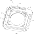
FIG. 1 is a schematic view of a three-dimensional structure of a plastic member according to an embodiment of the present application. -
FIG. 2 is a schematic view of a three-dimensional structure of a foaming member according to an embodiment of the present application. -
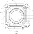
FIG. 3 is a front view of a water pan according to an embodiment of the present application. -
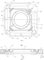
FIG. 4 is a rear view of a water pan according to an embodiment of the present application. -
FIG. 5 is a sectional view taken along A-A inFIG. 4 . -
FIG. 6 is a perspective view of a water pan according to an embodiment of the present application. -
FIG. 7 is a perspective view of a water pan according to another embodiment of the present application. -
FIG. 8 is a schematic view of an overall structure of a protective grille according to an embodiment of the present application. -
FIG. 9 is a schematic view of a protrusion of the protective grille shown inFIG. 8 . -
FIG. 10 is a schematic view of an overall structure of a screen assembly according to embodiments of the present application. -
FIG. 11 is a sectional view taken along A-A inFIG. 10 . -
- 1 negative ion generator; 2 temperature sensor;
- 10 plastic member; 11 air inlet; 12 air outlet; 13 connecting part; 14 supporting grille; 15 air guiding ring; 16 first frame; 17 water receiving sink;
- 20 foaming member; 22 wire slot; 23 air inlet avoidance hole; 24 air outlet avoidance hole; 25 second frame;
- 30 protective net;
- 31 body; 311 first button; 312 first hole; 313 connecting member; 3131 connecting member stiffener; 314 stiffener;
- 32 mounting part; 321 second button; 3211 first sub-button; 3212 second sub-button; 322 protrusion; 3221 first segment; 3222 second segment; 3223 curved surface; 323 second hole; 324 first wire clip; 325 second wire clip;
- 40 water pan.
- Embodiments of the present application are described in detail below, examples of which are shown in the accompanying drawing. The following embodiments described with reference to the accompanying drawing are illustrative. It should be understood that the embodiments described are intended to explain the present application, but not to limit the present application.
- Embodiments of the present application provide a water pan, the water pan is used for an air conditioner, which may improve the efficiency of air inlet and air outlet, has high overall structural stability, and may improve the convenience and accuracy of installation on an air conditioner. The air conditioner may be a central air conditioner, and the water pan may be installed on an indoor air inlet and outlet device of the central air conditioner.
- Referring to
FIG. 1 to FIG. 6 , the water pan of embodiments of the present application mainly includes two parts of aplastic member 10 and a foamingmember 20, and the two parts are connected as a whole and do not need to be connected by a screw and other connectors. Although the materials of theplastic member 10 and the foamingmember 20 are different, they have an integrally formed structure, and there is no need to assemble separately when in use, thus improving the convenience of installation, improving production efficiency, and further facilitating improvement of the accuracy of the relative position between theair inlet 11 and a related component of the air conditioner. - Referring to
FIG. 1 andFIG. 3 , anair inlet 11 is defined in a middle of theplastic member 10, anair outlet 12 is defined near an edge of theplastic member 10, and awater receiving sink 17 is defined between theair inlet 11 and theair outlet 12. Thewater receiving sink 17 surrounds theair inlet 11, and theair outlet 12 continuously surrounds at least part of an outer edge of thewater receiving sink 17. A plurality of supportinggrilles 14 is arranged in theair outlet 12, and the plurality of supportinggrilles 14 is distributed at intervals along an extension direction of theair outlet 12. In embodiments of the present application, only oneair outlet 12 is provided, and continuously surrounds thewater receiving sink 17, to form an annular air outlet, thus increasing the circulation area of theair outlet 12. Although the supportinggrille 14 is arranged in theair outlet 12, the circulation area of theair outlet 12 occupied by the supportinggrille 14 is very small, and the total circulation area of theair outlet 12 is far greater than the total circulation area of a plurality of air outlets provided in the related art. Thewater receiving sink 17 is arranged as a long strip shape and extends along a predetermined direction to contain the condensate water and transfer the collected condensate water to a preset pipe. In some embodiments, thewater receiving sink 17 is a continuous recess, and the condensate water may flow within thewater receiving sink 17. The supportinggrille 14 is a plate-like body, and a thickness of the supportinggrille 14 gradually decreases along an air outlet direction. That is, a width of a cross-section of the supportinggrille 14 at different locations may be different. The setting may not only reduce wind resistance, but also has the effect of reducing noise. - In the related art, the water pan is made of foam, and the strength of foam is low, so at the air outlet, a long connection structure needs to be provided to connect a frame, which will cause a larger area of blocking to the air outlet.
- In some embodiments, the foaming
member 20 is integrally formed with theplastic member 10. - In the present application, the water pan is made by foaming a foam material on the plastic member, the strength of the plastic member is high, the strength of the water pan formed by the process is high, and the section of the supporting
grille 14 for connecting afirst frame 16 at the air outlet may be made very small. As shown inFIG. 3 , the proportion of the wind shield area of the supportinggrille 14 in the air outlet to the total area of the air outlet is very small, which may even be ignored, so that the annular air outlet may be achieved. - For example, the
air outlet 12 is a bent long-strip hole with a certain length, and the width of theair outlet 12 may be set according to the actual design requirements. - The supporting
grille 14 plays the role of supporting and connection, which may be made as thin as possible under the premise of meeting the structural strength requirements, to reduce wind resistance. - Referring to
FIG. 2 , the foamingmember 20 and theplastic member 10 at least partially overlap with each other, which play a role of heat preservation, so that the water pan achieves the effect of anti-condensation. The foamingmember 20 avoids theair inlet 11 and theair outlet 12. The foamingmember 20 is connected with theplastic member 10 and is relatively fixed. In some embodiments, the foamingmember 20 is integrally formed with theplastic member 10, the foamingmember 20 defines thewater receiving sink 17, thewater receiving sink 17 surrounds theair inlet 11, and theair outlet 12 surrounds thewater receiving sink 17. Since the foamingmember 20 and theplastic members 10 are integrally formed, the foamingmember 20 and theplastic members 10 also do not need to be assembled separately. Although the materials of the foamingmember 20 and theplastic members 10 are different, they may be formed by injection molding. Therefore, the foamingmember 20 and theplastic members 10 may be casted respectively by controlling the casting sequence of different materials, and the foamingmember 20 and theplastic member 10 are connected as a whole. - In some embodiments, in order to avoid the
air inlet 11 and theair outlet 12, an airinlet avoidance hole 23 is defined in a middle of the foamingmember 20, and an airoutlet avoidance hole 24 is defined between asecond frame 25 and thewater receiving sink 17. The airinlet avoidance hole 23 corresponds in position to theair inlet 11, and the airoutlet avoidance hole 24 corresponds in position to theair outlet 12. The airinlet avoidance hole 23 is a circular shape matching theair inlet 11, and the airoutlet avoidance hole 24 is a bent long strip-shaped hole matching the shape of theair outlet 12. - In some embodiments, the supporting
grille 14 is arranged along a direction from theair inlet 11 to theair outlet 12, and a width of the supportinggrille 14 ranges from 1.5 mm to 3.2 mm. Since theplastic member 10 is made entirely of plastic material, the width of the supportinggrille 14 that is available for mold-opening may be controlled above 1.5 mm. According to the test and the needs of the structural strength of the water pan, in embodiments of the present application, the width of the supportinggrille 14 is limited to 3.2 mm. Thus, the width of the supportinggrille 14 may be 1.6 mm, 1.8 mm, 2.0 mm, 2.2 mm, 2.4 mm, 2.6 mm, 2.8 mm, 3.0 mm, etc. The supportinggrille 14 of the size not only has sufficient structural strength, but also causes very small wind resistance to theair outlet 12, which realizes a larger air outlet area and improves air outlet efficiency. - The width of the supporting
grille 14 mentioned here refers to the thickness of the cross-section of the supportinggrille 14 occupying theair outlet 12, that is, a distance between the two sides of the supportinggrille 14 inFIG. 3 . The supportinggrille 14 is a plate-like body, where the width of the supportinggrille 14 is the maximum thickness of the plate-like body. - The
plastic member 10 mainly plays the role of structural support for the whole water pan, and the foamingmember 20 mainly plays the role of heat preservation for the whole water pan. If the foamingmember 20 is provided with the supporting grille, because of the nature of the material itself, it is difficult to control the width of the supporting grille between 1.5 mm and 3.2 mm, and in the related art, in the solution of the foamingmember 20 provided with the supporting grille, the width of the provided supporting grille is usually about 10 mm, thus the wind resistance to theair outlet 12 is larger. - In some embodiments, the foaming
member 20 and theplastic member 10 are integrally formed, and the integral forming of theplastic member 10 and the foamingmember 20 may eliminate the assembly error and improve the fit clearance between an air guiding ring and a fan wheel of the air conditioner. The integral forming here means that the two are casted together during injection molding, so that the assembly step may be saved, the fit accuracy of the foamingmember 20 and theplastic member 10 is good, and the individual difference of the water pan is small. - In some embodiments, the process method of the integral forming of the foaming
member 20 and theplastic member 10 includes injection molding theplastic member 10, and directly casting a foam material on theplastic member 10 with a mold after the formedplastic member 10 is solidified, so that the foam material and theplastic member 10 are at least partially melted together, and the foam material is connected with theplastic member 10 after the foam material is solidified. - The structural strength of the
plastic member 10 is greater than that of the foamingmember 20. Therefore, theplastic member 10 is first injected molded, and the foam material is injected after theplastic member 10 is solidified to form the foamingmember 20 on theplastic member 10. Theplastic member 10 and the foamingmember 20 are at least partially melted together, so that theplastic member 10 and the foamingmember 20 form an integrally formed structure. Therefore, theplastic member 10 and the foamingmember 20 are inseparable two parts, and they do not have to be installed separately during the production of the air conditioner, thus the relative position of theplastic member 10 and the foamingmember 20 is very accurate, and no assembly errors will be generated. - When the foam material is casted, the surface of the
plastic member 10 in contact with it may be partially melted, to fuse with the foam material into a whole. The part of theplastic member 10 in contact with the foamingmember 20 may also not melt with each other. - In some embodiments, the width of the supporting
grille 14 ranges from 2 mm to 3 mm, for example from 2 mm to 2.5 mm. The size of the supportinggrille 14 not only has sufficient structural strength, but also causes very small wind resistance to theair outlet 12, which realizes a larger air outlet area and improves air outlet efficiency. - The
plastic member 10 has afirst frame 16, the supportinggrille 14 has a first end connected to thefirst frame 16, and a second end connected to the middle of theplastic member 10. Thefirst frame 16 is connected with thesecond frame 25, thefirst frame 16 plays a supporting role, and thesecond frame 25 plays a heat preservation role. - In some embodiments, a cross-section of the supporting
grille 14 gradually decreases along the air outlet direction, that is, the width of the cross-section of the supportinggrille 14 at different locations may not be equal. The setting further reduces wind resistance and has the effect of reducing noise. The directions of the arrows inFIG. 1 andFIG. 5 are the directions of air outlet and air inlet. - The supporting
grille 14 is a plate-like body, and the maximum width of the cross-section of the supportinggrille 14 ranges from 1.5 mm to 3.2 mm. - In some embodiments, the shape of the
air inlet 11 is circular and the shape of thewater receiving sink 17 is square shaped. The four corners of thewater receiving sink 17 are filleted, and the size of theair inlet 11 is matched with the size of the fan wheel of the air conditioner. In some embodiments, referring toFIG. 5 , the shape of theair inlet 11 is circular, and the inner diameter of theair inlet 11 gradually decreases along the direction of air inlet (from bottom to top). The structure is beneficial to improving the effect of air inlet and reducing the noise of air inlet. The directions of the arrows in theFIG. 5 are the directions of air inlet and air outlet. - In some embodiments, the
air outlet 12 surrounds the four outer sides of thewater receiving sink 17, and each outer side is connected to at least one supportinggrille 14. The setting ensures the stability of the overall structure of the water pan. - As an example, the
air outlet 12 has three bent positions, and two supportinggrilles 14 are provided at each bent position. A plane where the supportinggrille 14 is located coincides with a center of theair inlet 11. - In some embodiments, the
plastic member 10 has a plurality of connectingparts 13, and the connectingpart 13 penetrates the foamingmember 20. The connectingpart 13 may be used to connect the water pan to other components of the air conditioner, and the structural stability of the integral forming of theplastic member 10 and the foamingmember 20 may be improved by arranging the connectingpart 13 to penetrate the foamingmember 20. - For example, the connecting
part 13 may be a cylindrical structure, and a center of the connectingpart 13 may be provided with a threaded hole, thus the other components of the air conditioning unit may be installed with a water pan through the threaded hole. - In some embodiments, an
air guiding ring 15 is formed in the middle of theplastic member 10, theair inlet 11 is defined in a center of theair guiding ring 15, and theair guiding ring 15 and the foamingmember 20 do not overlap. Theplastic member 10 is an integral structure, and theair guiding ring 15 is a part of theplastic member 10. Therefore, the water pan of embodiments of the present application does not have to install an independent air guiding ring component when in use. In other words, the water pan of embodiments of the present application has the structure of the air guiding ring, and such arrangement makes the fit between theair guiding ring 15 and the fan wheel of the air conditioner more accurate. Since it is not necessary to install the air guiding ring component separately, the production efficiency of the air conditioner is also improved. - For example, an inner surface of the
air guiding ring 15 is a circular arc surface or a conical surface. The structure is beneficial to improving air inlet effect of theair inlet 11 and further reducing air inlet noise. - For example, referring to
FIG. 5 , the shape of the cross-section of theair guiding ring 15 may be a structure of 1/4 circular arc. - In some embodiments, referring to
FIG. 7 , theair inlet 11 is covered with aprotective net 30, and theprotective net 30 is detachably connected to the foamingmember 20 or theplastic member 10. The protective net 30 may play a protective role, and the protective net 30 may be made of stainless steel. Specifically, the protective net 30 may be connected with theplastic member 10 by a screw or by a snap. - In some embodiments, the protective net 30 may be a
grille 30. - In some embodiments, the foaming
member 20 is provided with a negative ion generator mounting part configured to mount a negative ion generator 1 and a temperature sensor mounting part configured to mount atemperature sensor 2, and the negative ion generator mounting part is located on a side of the temperature sensor mounting part. - Afloat may also be arranged on the foaming
member 20. Since the water pan takes into account the fixed assembly of the float, the negative ion generator 1 and thetemperature sensor 2, and has a corresponding structure to take into account the wire routing and fixation, without too much irrelevant structure, the overall volume is small and the material utilization is high in the premise of ensuring the structural strength. The negative ion generator 1 and thetemperature sensor 2 are arranged at an edge of theair inlet 11, so that thetemperature sensor 2 may detect the temperature, and the negative ion generator 1 may purify the air, conveniently. - The foaming
member 20 defines awire slot 22, and the connecting wire of electronic devices such as the negative ion generator 1, thetemperature sensor 2 and the like may pass through thewire slot 22. - In some embodiments, the number of
wire slot 22 is two, and the twowire slots 22 are respectively close to two extension ends of theair outlet 12, so that theair outlet 12 is a non-closed annular structure. - Embodiments of the present application further provide an air conditioner, and the air conditioner includes a water pan of any one of the embodiments. The installation of the water pan of the air conditioner is convenient, so that the production efficiency of the air conditioner is improved, and the width of the supporting
grille 14 is small, thus air outlet effect is good, and the user experience is improved. - As shown in
FIG. 8 , thegrille 30 according to embodiments of the present application includes abody 31, and thebody 31 is adapted to be connected with the water pan. Thebody 31 of thegrille 30 may play the role of filtration and ventilation. - In some embodiments, the
body 31 may be fixed to the water pan by a plurality of screws. - In some embodiments, as shown in
FIG. 8 andFIG. 10 , thebody 31 is provided with a plurality offirst buttons 311, and thefirst button 311 is adapted to be snap-fitted with the water pan to connect thebody 31 and thewater pan 40. Since thegrille 30 and thewater pan 40 are snap-fitted, the installation and disassembly of thegrille 30 and thewater pan 40 are convenient, and then the overhaul and maintenance are convenient. The situation that in the related art a panel may be installed and fixed with the help of manpower to lift the panel is avoided, which reduces the labor load and labor cost of workers, facilitates the alignment of the panel, and improves the installation efficiency. In addition, the situation that in the related art pre-embedded sheet metal parts on the water pan are easy to cause too many parts below the water pan and the production efficiency of the water pan is low is also avoided. - As shown in
FIG. 8 , thebody 31 may be circular, and it is understood that thebody 31 may also be square, star, oval, and other shapes. - In some embodiments, the
first button 311 may be a snap. A plurality offirst buttons 311 may be arranged at intervals along a circumferential direction of thebody 31, and when thegrille 30 is installed, the plurality offirst buttons 311 and the water pan may be clamped and fixed. - In some embodiments, the plurality of
first buttons 311 is arranged at intervals along the circumferential direction of the body 1, and the plurality offirst buttons 311 is adapted to be snapped with or separated from the water pan when thebody 31 rotates with respect to the water pan. - In some embodiments, as shown in
FIG. 8 , thefirst button 311 may also be a rotary button, and the plurality offirst buttons 311 are located at an edge of thebody 31 and are arranged at equal intervals along the circumferential direction of thebody 31. When installing thegrille 30, thegrille 30 may be rotated, and during rotation, the plurality offirst buttons 311 on thebody 31 may be clamped with thewater pan 40, so that the installation and fixing of thegrille 30 and thewater pan 40 may be realized. When thegrille 30 needs to be disassembled, thegrille 30 may be reversely rotated. Thus, the installation and disassembly of thegrille 30 are further facilitated. - In some embodiments, the
body 31 is provided with a first hole 312, the first hole 312 is adapted for insertion of a first fastener, and thebody 31 is detachably connected to thewater pan 40 by the first fastener. - Referring to
FIG. 8 , the first hole 312 may be located at the edge of thebody 31, the first fastener may be a bolt or a screw, and when thegrille 30 and thewater pan 40 are rotationally clamped or snap-fitted, thegrille 30 and thewater pan 40 may be connected and fixed by the first fastener, thus limiting the rotation of thegrille 30, and avoiding the situation that thegrille 30 is loosened and drops out due to rotate. - Only one first fastener may be provided, and the disassembly of the
grille 30 may be achieved by disassembling the first fastener and then unlocking eachfirst button 311, thus avoiding the situation that a plurality of screws needs to be disassembled in the related art, improving the installation and disassembly efficiency of thegrille 30, and facilitating the overhaul and maintenance. - In some embodiments, the
body 31 is provided with astiffener 314 which is arranged between adjacent twofirst buttons 311 and extends along the circumferential direction of thebody 31. As shown inFIG. 8 , thestiffener 314 may be located at an outer peripheral edge of thebody 31, thestiffener 314 may bend and extend in the circumferential direction of thebody 31, one end of thestiffener 314 may be connected with one of the adjacent twofirst buttons 311, and the other end of thestiffener 314 may be connected with the other of the adjacent twofirst buttons 311, thus enhancing the structural strength of thebody 31, and ensuring the structural stability of the shape of thebody 31. - In some embodiments, the
stiffener 314 and the body 31is integrally injection molded. - In some embodiments, the material of the
body 31 is plastic. The plastic material facilitates the injection molding of thegrille 30, and since thebody 31 is provided with stiffener, thegrille 30 still has high structural strength, avoiding the situation that the shape of thebody 31 is easy to deform when the plastic is adopted. - In some embodiments, the
stiffener 314 is plural, and the plurality ofstiffeners 314 and the plurality offirst buttons 311 are alternately arranged along the circumferential direction of thebody 31. - As shown in
FIG. 8 , an outer peripheral side of thebody 31 is provided with the plurality ofstiffeners 314, the number of thestiffener 314 may be the same as the number of thefirst button 311, and the plurality ofstiffeners 314 and the plurality offirst buttons 311 may be alternately arranged one by one along the circumferential direction of thebody 31. That is, any adjacent twofirst buttons 311 are provided with onestiffener 314 therebetween and are connected by thestiffener 314. Therefore, the structure strength of the outer peripheral edge of thebody 31 is higher, and the stability of the shape of thebody 31 is further ensured. - In some embodiments, the
stiffener 314 may be provided only in part between the adjacent twofirst buttons 311. - In some embodiments, the first hole 312 is located in the
stiffener 314. Specifically, the first hole 312 may be defined in thestiffener 314 and run through thebody 31 along a thickness direction of thebody 31. Thus, the situation that the local structural strength of thebody 31 is weak due to the arrangement of the first hole 312 is avoided. - In some embodiments, the
grille 30 also includes a mountingpart 32 located on the outer peripheral side of thebody 31, and the mountingpart 32 is adapted to mount thetemperature sensor 2 and/or the negative ion generator 1. The mountingpart 32 may play the role of fixing thetemperature sensor 2 and the negative ion generator 1. - As shown in
FIG. 8 , the mountingpart 32 may be integrally arranged with thebody 31. In some embodiments, the mountingpart 32 may also be detachably fixed with thebody 31. For example, the mountingpart 32 may be fixed to thebody 31 by a screw. The mountingpart 32 is fixed on the outer peripheral side of thebody 31, and the mountingpart 32 may be configured to fix thetemperature sensor 2, or to fix the negative ion generator 1. It is understood that the mountingpart 32 may also fix thetemperature sensor 2 and the negative ion generator 1 simultaneously. - On the one hand, the arrangement of the mounting
part 32 plays the role of fixing thetemperature sensor 2 and the negative ion generator 1, facilitating the installation of thetemperature sensor 2 and the negative ion generator 1. On the other hand, thetemperature sensor 2 and the negative ion generator 1 on the mountingpart 32 will not block the position of thebody 31, avoiding the impact of thetemperature sensor 2 and the negative ion generator 1 on a return air area of the air outlet, and further facilitating the improvement of the cooling efficiency of the air conditioner. - In some embodiments, the mounting
part 32 is provided with asecond button 321, and thetemperature sensor 2 is clamped and fixed on the mountingpart 32 by thesecond button 321. Specifically, as shown inFIG. 8 , thesecond button 321 is a snap, and thesecond button 321 may be integrally arranged on the mountingpart 32. When thetemperature sensor 2 is installed, thetemperature sensor 2 may be directly clamped and fixed by thesecond button 321, thus facilitating the installation and disassembly of thetemperature sensor 2. - In some embodiments, the
second button 321 includes afirst sub-button 3211 and asecond sub-button 3212, thefirst sub-button 3211 and thesecond sub-button 3212 are arranged at intervals, and thetemperature sensor 2 is clamped and fixed between thefirst sub-button 3211 and thesecond sub-button 3212. Specifically, as shown inFIG. 8 , the mountingpart 32 may be located below the rear of thebody 31, thefirst sub-button 3211 and thesecond sub-button 3212 may be arranged at intervals along the front and rear direction, and when thetemperature sensor 2 is installed, a front side of thetemperature sensor 2 is clamped and fixed to thefirst sub-button 3211, and a rear side of thetemperature sensor 2 is clamped and fixed to thesecond sub-button 3212, so that the fixation strength of thetemperature sensor 2 is ensured. - In some embodiments, a
protrusion 322 is provided on the mountingpart 32, and theprotrusion 322 is adapted to abut against the negative ion generator 1 to limit the negative ion generator 1. Theprotrusion 322 includes afirst segment 3221 and asecond segment 3222. Thefirst segment 3221 has a convex surface and a concave surface arranged opposite each other, the convex surface is adapted to abut against the negative ion generator 1 to limit the negative ion generator 1, thesecond segment 3222 is arranged on a side of the concave surface of thefirst segment 3221, and thesecond segment 3222 is connected with the concave surface. - As shown in
FIG. 8 , theprotrusion 322 may be integrally arranged on the mountingpart 32, and theprotrusion 322 may be a bulge or a projection on the mountingpart 32. After the negative ion generator 1 is installed on the mountingpart 32, theprotrusion 322 may stop a side wall of the negative ion generator 1, thus playing the effect of limiting the position, enhancing the fixing compactness of the negative ion generator 1, and avoiding the situation that the negative ion generator 1 shakes freely. When the negative ion generator 1 is fixed by a screw, the number of screws used may also be reduced, thus facilitating the installation and disassembly of the negative ion generator 1, and further facilitating maintenance. - In some embodiments, a plurality of
protrusions 322 may be provided, thus the restriction of multiple positions of the negative ion generator 1 may be realized. - In some embodiments, the
protrusion 322 has an arc-shapedsurface 3223 which is adapted to fit with an outer peripheral wall of the negative ion generator 1. Specifically, the outer peripheral surface of theprotrusion 322 may include the arc-shapedsurface 3223 which is a circular arc surface, and the outer surface of the negative ion generator 1 may define a groove part. When the negative ion generator 1 is installed on the mountingpart 32, the arc-shapedsurface 3223 may be fitted with the groove part snugly, further enhancing the fixing effect of the negative ion generator 1, and avoiding the loosening of the negative ion generator 1. - In some embodiments, the
protrusion 322 includes thefirst segment 3221 and thesecond segment 3222, thefirst segment 3221 is arc-shaped, thefirst segment 3221 has a convex surface and a concave surface, which are arranged opposite each other, the convex surface is adapted to fit with the outer peripheral wall of the negative ion generator 1, thesecond segment 3222 is arranged on a side of the concave surface of thefirst segment 3221, and thesecond segment 3222 is connected with the concave surface. - In some embodiments, the
protrusion 322 includes thefirst segment 3221 and thesecond segment 3222, thefirst segment 3221 is arc-shaped, thefirst segment 3221 has a convex surface and a concave surface which are arranged opposite each other, at least part of the convex surface forms the arc-shapedsurface 3223, thesecond segment 3222 is located on a side of the concave surface of thefirst segment 322, and thesecond segment 3222 is connected with the concave surface. - As shown in
FIG. 9 , theprotrusion 322 may be composed of thefirst segment 3221 and thesecond segment 3222, thefirst segment 3221 is circular arc-shaped, thesecond segment 3222 is linear, thesecond segment 3222 is located on the side of the concave surface of thefirst segment 3221, thesecond segment 3222 extends roughly along a diameter of a circle corresponding to thefirst segment 3221, and one end of thesecond segment 3222 is connected with a middle of thefirst segment 3221. The convex surface is used to fit and contact with the outer peripheral wall of the negative ion generator 1. - The arc-shaped
surface 3223 is located on the convex surface of thefirst segment 3221. Thus, on the one hand, the structure of theprotrusion 322 is simplified, which is conducive to reducing the consumables of theprotrusion 322, and plays a role in reducing the cost. On the other hand, it ensures that theprotrusion 322 has high structural strength, to meet the requirements of the fitting limit. - In some embodiments, a
second hole 323 is defined in the mountingpart 32, the negative ion generator 1 is detachably mounted on the mountingpart 32 by a second fastener, and thesecond hole 323 is adapted to inserting the second fastener. As shown inFIG. 8 , the mountingpart 32 may be provided with twosecond holes 323, and the twosecond hole 323 may be respectively located at the positions near therespective projections 322. When installing the negative ion generator 1, the negative ion generator 1 may be positioned through theprojection 322, and then the corresponding second fastener may be fixed in the corresponding first hole 312, and the second fastener may be a bolt or a screw. - In some embodiments, the
body 31 and the mountingpart 32 are integrally injection molded. For example, thebody 31 and the mountingpart 32 may be casted by plastic injection molding, thus facilitating the processing of thegrille 30 and improving production efficiency. - In some embodiments, the
body 31 is provided with a plurality of connectingmembers 313, the plurality of connectingmembers 313 are arranged at intervals along the circumferential direction of thebody 31, and the connectingmember 313 is adapted to pre-hang with a panel. - In some embodiments, the
body 31, the connectingmember 313, and the mountingpart 32 are all integrally injection molded. Specifically, thebody 31, the connectingmember 313 and the mountingpart 32 may be casted by plastic injection molding, thus facilitating the processing of thegrille 30 and improving production efficiency. - In some embodiments, a plurality of connecting
members 313 may be provided, the plurality of connectingmembers 313 is fixed on thebody 31 and arranged at equal intervals along the circumferential direction of thebody 31, and the connectingmember 313 may achieve temporary pre-connection of the panel of the air conditioner. - In some embodiments, the plurality of connecting
members 313 may also be located on an outer peripheral surface of thebody 31 and arranged at intervals along the circumferential direction of thebody 31. As shown inFIG. 8 , four connectingmembers 313 may be provided, the four connectingmembers 313 are located on the outer peripheral surface of the body 131, and the four connectingmembers 313 are arranged at equal intervals along the circumferential direction of thebody 31, that is, the center angle of the arc between any adjacent two connectingmembers 313 is 90 degrees. - When installing the panel of the air conditioner, the panel may be first connected and fixed by the connecting
member 313, and the connectingmember 313 may realize the pre-positioning of the panel, thus facilitating the alignment of the panel, and further facilitating the operator to fix the panel by a screw. Secondly, during the maintenance process, the hanging of a disassembled panel may also be realized, thus providing convenience for maintenance. - As shown in
FIG. 11 , the connectingmember 313 may be a hook, and the hook is adapted to pre-hang with the panel, so that the connection may be connected to the panel by hooking. The hook may realize the hanging of the panel of the air conditioner, to achieve the pre-positioning of the panel. - In some embodiments, the hook may also be provided with a plurality of connecting
member stiffeners 3131 extending along a bending direction of the hook, and the plurality of connectingmember stiffeners 3131 is arranged at intervals along a width direction of the hook. - As shown in
FIG. 8 andFIG. 11 , thebody 31 may be provided with a plurality of hooks, the hook may be located on the outer peripheral side of thebody 31, and the hook may be bent towards an outer side of thebody 31. The outer surface of the hook may be provided with three connectingmember stiffeners 3131, the three connectingmember stiffeners 3131 are arranged at equal intervals along the width direction of the hook, and the three connectingmember stiffeners 3131 extend along the bending extension direction of the hook. The connectingmember stiffener 3131 may play a role in strengthening the structural strength of the connectingmember 313. - In some embodiments, the connecting
member 313 may also be a magnet adapted for magnetic connection with the panel. In some embodiments, the connectingmember 313 may also be a button, a snap fastener, a touch fastener, etc., thus, facilitating the connection and disassembly of the panel of the air conditioner and the connecting member 1213. - In some embodiments, the mounting
part 32 and/or thebody 31 are provided with afirst wire clip 324 and asecond wire clip 325, thefirst wire clip 324 is adapted to clamp a wire of thetemperature sensor 2, and thesecond wire clip 325 is adapted to clamp a wire of the negative ion generator 1. - As shown in
FIG. 8 , thefirst wire clip 324 and thesecond wire clip 325 may both be snapping slots. When thetemperature sensor 2 is fixed on the mountingpart 32, the wire of thetemperature sensor 2 may be stuck in thefirst wire clip 324; when the negative ion generator 1 is fixed on the mountingpart 32, the wire of the negative ion generator 1 may be stuck in thesecond wire clip 325. On the one hand, the arrangement of thefirst wire clip 324 and thesecond wire clip 325 facilitates the routing of the wire, and on the other hand, the arrangement and planning of the wire may be realized, to avoid the situation of the disordered distribution of the wire. - In some embodiments, the outer peripheral side of the
body 31 is integrally formed with a mounting seat, and thefirst wire clip 324 may be arranged on the mounting seat. - An air conditioner indoor unit according to embodiments of the present application is described below with reference to the accompanying drawings.
- As shown in
FIG. 10 and FIG. 11 , the air conditioner indoor unit according to embodiments of the present application includes a grille, the grille may be thegrille 30 described in the above embodiments. Specifically, the air conditioner indoor unit may also include atemperature sensor 2, a negative ion generator 1, and a water pan. The water pan may be a water pan described in embodiments of the present application. - In some embodiments, as shown in
FIG. 10 , thewater pan 40 is roughly annular shaped, and thegrille 30 may be detachably installed in thewater pan 40 by a screw and a rotary button. Thetemperature sensor 2 and the negative ion generator 1may both be installed on the mountingpart 32 of thegrille 30. - In some embodiments, the
temperature sensor 2 and the negative ion generator 1 may both be mounted on the mountingpart 32 of thegrille 30. The temperature sensing pack 200 is clamped and fixed by thefirst button 321, and the negative ion generator 1 is fixed by thefirst hole 323 and theprotrusion 322. Thetemperature sensor 2 and the negative ion generator 1 are located on the outer peripheral side of the body 1 of thegrille 30. - According to the air conditioner indoor unit in embodiments of the present application, the protective grille of the air conditioner indoor unit is convenient to install and disassemble, which facilitates overhaul and maintenance, reduces labor load and labor cost of workers, and improves the installation efficiency.
- In the description of the present application, it should be understood that the orientation or position relationship indicated by the terms "center", "longitudinal", "transverse", "length", "width", "thickness", "up", "down", "front", "rear", "left", "right" , "vertical", "horizontal", "top", "bottom", "inner", "outer", "clockwise", "counterclockwise", "axial", "radial" and "circumferential" and the like, is based on the orientation or position relationship shown in the accompanying drawings, which is only for the convenience of describing the present application and simplifying the description, and does not indicate or imply that the referred device or element must have a specific orientation, and be constructed and operated in a specific orientation, so it cannot be understood as a limitation of the present application.
- In addition, the terms "first" and "second" are only used for purpose of description, and cannot be understood as indicating or implying relative importance or implicitly indicating the number of indicated technical features. Therefore, the feature defined as "first" or "second" may explicitly or implicitly include at least one such feature. In the description of the present application, "a plurality of' means at least two, such as two, three, etc., unless otherwise specifically defined.
- In the present application, unless otherwise expressly defined, terms such as "install/mount", "interconnect", "connect", "fix" shall be understood broadly, and may be, for example, fixed connections, detachable connections, or integral connections; may also be mechanical or electrical connections or intercommunication; may also be direct connections or indirect connections via intervening media; may also be inner communications or interactions of two elements, unless otherwise specifically defined. For those skilled in the art, the specific meaning of the above terms in the present application can be understood according to the specific situations.
- In the present application, unless otherwise expressly defined and specified, a structure in which a first feature is "on" or "below" a second feature may include an embodiment in which the first feature is in direct contact with the second feature, or may further include an embodiment in which the first feature and the second feature are in indirect contact through intermediate media. Furthermore, a first feature "on", "above", or "on top of' a second feature may include an embodiment in which the first feature is right or obliquely "on", "above", or "on top of" the second feature, or just means that the first feature is at a height higher than that of the second feature, while a first feature "below", "under", or "on bottom of' a second feature may include an embodiment in which the first feature is right or obliquely "below", "under", or "on bottom of' the second feature, or just means that the first feature is at a height lower than that of the second feature.
- In the description of the present application, terms such as "an embodiment", "some embodiments", "an example", "a specific example" or "some examples" means that a particular feature, structure, material, or characteristic described in connection with the embodiment or example is included in at least one embodiment or example of the present application. Thus, the appearances of these terms in various places throughout this specification are not necessarily referring to the same embodiment or example of the present application. Furthermore, the particular features, structures, materials, or characteristics may be combined in any suitable manner in one or more embodiments or examples. In addition, without contradiction, those skilled in the art may combine and unite different embodiments or examples or features of the different embodiments or examples described in this specification.
- Although the embodiments of the present application have been shown and described above, it can be understood that the above embodiments are illustrative and shall not be understood as limitation to the present application, and changes, modifications, alternatives and variations can be made in the above embodiments within the scope of the present application by those skilled in the art.
Claims (20)
- A water pan, comprising:a plastic member (10), an air inlet (11) being defined in a middle of the plastic member (10), an air outlet (12) being defined near an edge of the plastic member (10), a water receiving sink (17) being defined between the air inlet (11) and the air outlet (12), the water receiving sink (17) surrounding the air inlet (11), the air outlet (12) continuously surrounding at least part of an outer edge of the water receiving sink (17), a plurality of supporting grilles (14) being arranged in the air outlet (12), the plurality of supporting grilles (14) being distributed at intervals along an extension direction of the air outlet (12); anda foaming member (20), the foaming member (20) and the plastic member (10) at least partially overlapping with each other, the foaming member (20) avoiding the air inlet (11) and the air outlet (12).
- The water pan according to claim 1, wherein the foaming member (20) and the plastic member (10) are integrally formed.
- The water pan according to claim 1, wherein the supporting grille (14) is arranged along a direction from the air inlet (11) to the air outlet (12).
- The water pan according to claim 1, wherein an air inlet avoidance hole (23) is defined in a middle of the foaming member (20), an air outlet avoidance hole (24) is defined between a second frame (25) and the water receiving sink (17), the air inlet avoidance hole (23) corresponds in position to the air inlet (11), and the air outlet avoidance hole (24) corresponds in position to the air outlet (12).
- The water pan according to claim 4, wherein the plastic member (10) has a first frame (16), the supporting grille (14) has a first end connected to the first frame (16), and a second end connected to the middle of the plastic member (10); and
the first frame (16) is connected with the second frame (25). - The water pan according to claim 1 or 2, wherein a cross-section of the supporting grille (14) gradually decreases along an air outlet direction.
- The water pan according to claim 1, wherein a width of the supporting grille (14) ranges from 1.5 mm to 3.2 mm.
- The water pan according to claim 2, wherein the foaming member (20) are integrally formed with the plastic member (10) by injection molding the plastic member (10), and directly casting a foam material on the plastic member (10) with a mold after the formed plastic member (10) is solidified, so that the foam material and the plastic member (10) are at least partially melted together, and the foam material is connected with the plastic member (10) after the foam material is solidified.
- The water pan according to claim 6, wherein the water receiving sink (17) is a square ring structure; the air outlet (12) surrounds four outer sides of the water receiving sink (17), and each outer side is connected to at least one supporting grille (14).
- The water pan according to claim 1, wherein the plastic member (10) has a plurality of connecting parts (13), and the connecting part (13) penetrates the foaming member (20).
- The water pan according to claim 1, wherein an air guiding ring (15) is formed in the middle of the plastic member (10), the air inlet (11) is defined in a center of the air guiding ring (15), and the air guiding ring (15) and the foaming member (20) do not overlap.
- The water pan according to claim 1, wherein the air inlet (11) is covered with a protective net (30), and the protective net (30) is detachably connected to the foaming member (20) or the plastic member (10).
- The water pan according to claim 1, wherein the foaming member (20) is provided with a negative ion generator mounting part configured to mount a negative ion generator (1) and a temperature sensor mounting part configured to mount a temperature sensor (2), and the negative ion generator (1) mounting part is located on a side of the temperature sensor mounting part.
- The water pan according to claim 13, wherein the foaming member (20) defines a wire slot (22), the wire slot (22) is close to the air outlet (12) and configured for pass through of connecting wires of the negative ion generator (1) and the temperature sensor (2).
- The water pan according to claim 12, wherein the protective net (30) is a grille, the grille comprises a body (31), the body (31) is adapted to be connected with the water pan, the body (31) is provided with a plurality of first buttons (311), and the first button (311) is adapted to be snap-fitted with the water pan to connect the body (31) and the water pan.
- The water pan according to claim 15, wherein the grille further comprises a mounting part (32), the mounting part (32) is located on an outer peripheral side of the body (31), and the mounting part (32) is adapted to mount the temperature sensor (2) and/or the negative ion generator (1).
- The water pan according to claim 16, wherein the body (31) and the mounting part (32) are integrally injection molded.
- The water pan according to claim 16 or 17, wherein a protrusion (322) is provided on the mounting part (32), the protrusion (322) comprises a first segment (3221) and a second segment (3222), the first segment (3221) has a convex surface and a concave surface arranged opposite each other, the convex surface is adapted to abut against the negative ion generator (1) to limit the negative ion generator (1), the second segment (3222) is arranged on a side of the concave surface of the first segment (3221), and the second segment (3222) is connected with the concave surface.
- The water pan according to claim 16 or 17, wherein the mounting part (32) and/or the body (31) are provided with a first wire clip (324) and a second wire clip (325), the first wire clip (324) is adapted to clamp a wire of the temperature sensor (2), and the second wire clip (325) is adapted to clamp a wire of the negative ion generator (1).
- An air conditioner, comprising a water pan according to any one of claim 1 to 19.
Applications Claiming Priority (7)
| Application Number | Priority Date | Filing Date | Title |
|---|---|---|---|
| CN202122406360.XU CN216203737U (en) | 2021-09-30 | 2021-09-30 | Air conditioner indoor unit and grille thereof |
| CN202122409109.9U CN216346973U (en) | 2021-09-30 | 2021-09-30 | Grille and air conditioner indoor unit |
| CN202122406427.XU CN216204250U (en) | 2021-09-30 | 2021-09-30 | Water collector and air conditioner |
| CN202111165079.XA CN115900035A (en) | 2021-09-30 | 2021-09-30 | Water collector and air conditioner |
| CN202122410353.7U CN216204251U (en) | 2021-09-30 | 2021-09-30 | Water collector and air conditioner |
| CN202122406399.1U CN216346972U (en) | 2021-09-30 | 2021-09-30 | Grille and air conditioner indoor unit |
| PCT/CN2022/097737 WO2023050864A1 (en) | 2021-09-30 | 2022-06-08 | Drain pan and air conditioner |
Publications (2)
| Publication Number | Publication Date |
|---|---|
| EP4411270A1 true EP4411270A1 (en) | 2024-08-07 |
| EP4411270A4 EP4411270A4 (en) | 2025-01-15 |
Family
ID=85781257
Family Applications (1)
| Application Number | Title | Priority Date | Filing Date |
|---|---|---|---|
| EP22874262.3A Pending EP4411270A4 (en) | 2021-09-30 | 2022-06-08 | DRAIN TRAY AND AIR CONDITIONER |
Country Status (7)
| Country | Link |
|---|---|
| US (1) | US20240302074A1 (en) |
| EP (1) | EP4411270A4 (en) |
| JP (1) | JP7811222B2 (en) |
| KR (1) | KR20230175291A (en) |
| AU (1) | AU2022355725B2 (en) |
| CA (1) | CA3221401A1 (en) |
| WO (1) | WO2023050864A1 (en) |
Families Citing this family (1)
| Publication number | Priority date | Publication date | Assignee | Title |
|---|---|---|---|---|
| CN220103400U (en) * | 2023-05-10 | 2023-11-28 | 广东美的暖通设备有限公司 | Base assembly and air conditioner |
Family Cites Families (18)
| Publication number | Priority date | Publication date | Assignee | Title |
|---|---|---|---|---|
| JPS616115U (en) * | 1984-06-16 | 1986-01-14 | 日泉化学工業株式会社 | insulated drain pan |
| KR100697194B1 (en) * | 2001-06-25 | 2007-03-21 | 주식회사 엘지이아이 | Drain pan fixing structure of ceiling type air conditioner |
| JP4103610B2 (en) * | 2003-01-30 | 2008-06-18 | 三菱電機株式会社 | Recessed ceiling air conditioner |
| JP5096693B2 (en) * | 2006-05-17 | 2012-12-12 | 東芝キヤリア株式会社 | Embedded ceiling air conditioner |
| JP2014129927A (en) * | 2012-12-28 | 2014-07-10 | Daikin Ind Ltd | Ceiling installation indoor unit |
| JP6481817B2 (en) * | 2015-03-24 | 2019-03-13 | 株式会社富士通ゼネラル | Embedded ceiling air conditioner |
| JP6516095B2 (en) * | 2015-04-27 | 2019-05-22 | 株式会社富士通ゼネラル | Ceiling-mounted air conditioner |
| CN106403016B (en) * | 2015-07-30 | 2019-07-26 | Lg电子株式会社 | The indoor unit of air conditioner |
| CN108105973B (en) * | 2017-12-08 | 2024-05-24 | 珠海格力节能环保制冷技术研究中心有限公司 | Air inlet grille, panel structure and air conditioner |
| KR102551118B1 (en) * | 2018-03-26 | 2023-07-05 | 엘지전자 주식회사 | Indoor unit of air conditioner |
| CN208186802U (en) * | 2018-04-27 | 2018-12-04 | 广东美的制冷设备有限公司 | Drip tray and air-conditioning equipment |
| KR102269632B1 (en) * | 2018-11-30 | 2021-06-28 | 박도형 | Drain pan manufacturing system for ceiling type air conditioner and manufacturing method using the same |
| CN211822765U (en) * | 2020-02-18 | 2020-10-30 | 海信(山东)空调有限公司 | Ceiling machine |
| CN216346973U (en) * | 2021-09-30 | 2022-04-19 | 广东美的暖通设备有限公司 | Grille and air conditioner indoor unit |
| CN216203737U (en) * | 2021-09-30 | 2022-04-05 | 广东美的暖通设备有限公司 | Air conditioner indoor unit and grille thereof |
| CN216204251U (en) * | 2021-09-30 | 2022-04-05 | 广东美的暖通设备有限公司 | Water collector and air conditioner |
| CN216204250U (en) * | 2021-09-30 | 2022-04-05 | 广东美的暖通设备有限公司 | Water collector and air conditioner |
| CN216346972U (en) * | 2021-09-30 | 2022-04-19 | 广东美的暖通设备有限公司 | Grille and air conditioner indoor unit |
-
2022
- 2022-06-08 WO PCT/CN2022/097737 patent/WO2023050864A1/en not_active Ceased
- 2022-06-08 JP JP2023572944A patent/JP7811222B2/en active Active
- 2022-06-08 US US18/563,969 patent/US20240302074A1/en not_active Abandoned
- 2022-06-08 EP EP22874262.3A patent/EP4411270A4/en active Pending
- 2022-06-08 AU AU2022355725A patent/AU2022355725B2/en active Active
- 2022-06-08 KR KR1020237040441A patent/KR20230175291A/en not_active Ceased
- 2022-06-08 CA CA3221401A patent/CA3221401A1/en active Pending
Also Published As
| Publication number | Publication date |
|---|---|
| EP4411270A4 (en) | 2025-01-15 |
| AU2022355725A1 (en) | 2023-12-14 |
| CA3221401A1 (en) | 2023-04-06 |
| AU2022355725B2 (en) | 2025-04-10 |
| JP2024519160A (en) | 2024-05-08 |
| KR20230175291A (en) | 2023-12-29 |
| WO2023050864A1 (en) | 2023-04-06 |
| JP7811222B2 (en) | 2026-02-04 |
| US20240302074A1 (en) | 2024-09-12 |
Similar Documents
| Publication | Publication Date | Title |
|---|---|---|
| EP2056028B1 (en) | Outdoor unit of air conditioner | |
| US20240302074A1 (en) | Drain pan and air conditioner | |
| CN209180079U (en) | Blower, fresh air module and air conditioner | |
| WO2026046406A1 (en) | Indoor air-conditioning unit | |
| CN111237877A (en) | Fresh air device and air conditioner indoor unit with same | |
| US12379132B1 (en) | Air conditioner | |
| CN215637590U (en) | Wall Mounted Air Conditioner | |
| CN113251651A (en) | Air conditioner | |
| CN211119907U (en) | Electric control box components, air conditioning indoor units and air conditioners | |
| CN216203737U (en) | Air conditioner indoor unit and grille thereof | |
| CN216346973U (en) | Grille and air conditioner indoor unit | |
| EP4692668A1 (en) | Fixing member, housing assembly, and heating, ventilation, and air conditioning device | |
| CN216346972U (en) | Grille and air conditioner indoor unit | |
| CN212511416U (en) | Air conditioner indoor unit and air conditioner | |
| CN212618719U (en) | Air conditioner indoor unit and air conditioner | |
| CN205860270U (en) | The snow shed of air-conditioner outdoor unit and air-conditioner outdoor unit | |
| CN216204251U (en) | Water collector and air conditioner | |
| CN213514124U (en) | Machine and air conditioner in air conditioning | |
| CN223580066U (en) | air conditioner | |
| CN211977036U (en) | Cabinet air conditioner and air conditioner | |
| CN216953272U (en) | Air conditioner | |
| CN110762624A (en) | Air conditioner | |
| CN223580194U (en) | Rear box body part and air conditioner | |
| CN213272834U (en) | Air conditioner indoor unit and air conditioner | |
| CN113959000A (en) | Air conditioner indoor unit and air conditioner |
Legal Events
| Date | Code | Title | Description |
|---|---|---|---|
| STAA | Information on the status of an ep patent application or granted ep patent |
Free format text: STATUS: THE INTERNATIONAL PUBLICATION HAS BEEN MADE |
|
| PUAI | Public reference made under article 153(3) epc to a published international application that has entered the european phase |
Free format text: ORIGINAL CODE: 0009012 |
|
| STAA | Information on the status of an ep patent application or granted ep patent |
Free format text: STATUS: REQUEST FOR EXAMINATION WAS MADE |
|
| 17P | Request for examination filed |
Effective date: 20231123 |
|
| AK | Designated contracting states |
Kind code of ref document: A1 Designated state(s): AL AT BE BG CH CY CZ DE DK EE ES FI FR GB GR HR HU IE IS IT LI LT LU LV MC MK MT NL NO PL PT RO RS SE SI SK SM TR |
|
| DAV | Request for validation of the european patent (deleted) | ||
| DAX | Request for extension of the european patent (deleted) | ||
| A4 | Supplementary search report drawn up and despatched |
Effective date: 20241218 |
|
| RIC1 | Information provided on ipc code assigned before grant |
Ipc: F24F 8/30 20210101ALI20241212BHEP Ipc: F24F 1/0007 20190101ALI20241212BHEP Ipc: F24F 13/08 20060101ALI20241212BHEP Ipc: F24F 13/22 20060101AFI20241212BHEP |