EP4411091A1 - Verfahren zur installation eines turms und mit diesem verfahren installierter turm - Google Patents
Verfahren zur installation eines turms und mit diesem verfahren installierter turm Download PDFInfo
- Publication number
- EP4411091A1 EP4411091A1 EP22875243.2A EP22875243A EP4411091A1 EP 4411091 A1 EP4411091 A1 EP 4411091A1 EP 22875243 A EP22875243 A EP 22875243A EP 4411091 A1 EP4411091 A1 EP 4411091A1
- Authority
- EP
- European Patent Office
- Prior art keywords
- mounting
- tower
- crane
- stacked
- length
- Prior art date
- Legal status (The legal status is an assumption and is not a legal conclusion. Google has not performed a legal analysis and makes no representation as to the accuracy of the status listed.)
- Pending
Links
Images
Classifications
-
- B—PERFORMING OPERATIONS; TRANSPORTING
- B66—HOISTING; LIFTING; HAULING
- B66C—CRANES; LOAD-ENGAGING ELEMENTS OR DEVICES FOR CRANES, CAPSTANS, WINCHES, OR TACKLES
- B66C23/00—Cranes comprising essentially a beam, boom, or triangular structure acting as a cantilever and mounted for translatory of swinging movements in vertical or horizontal planes or a combination of such movements, e.g. jib-cranes, derricks, tower cranes
- B66C23/18—Cranes comprising essentially a beam, boom, or triangular structure acting as a cantilever and mounted for translatory of swinging movements in vertical or horizontal planes or a combination of such movements, e.g. jib-cranes, derricks, tower cranes specially adapted for use in particular purposes
- B66C23/185—Cranes comprising essentially a beam, boom, or triangular structure acting as a cantilever and mounted for translatory of swinging movements in vertical or horizontal planes or a combination of such movements, e.g. jib-cranes, derricks, tower cranes specially adapted for use in particular purposes for use erecting wind turbines
-
- E—FIXED CONSTRUCTIONS
- E04—BUILDING
- E04H—BUILDINGS OR LIKE STRUCTURES FOR PARTICULAR PURPOSES; SWIMMING OR SPLASH BATHS OR POOLS; MASTS; FENCING; TENTS OR CANOPIES, IN GENERAL
- E04H12/00—Towers; Masts or poles; Chimney stacks; Water-towers; Methods of erecting such structures
- E04H12/02—Structures made of specified materials
- E04H12/12—Structures made of specified materials of concrete or other stone-like material, with or without internal or external reinforcements, e.g. with metal coverings, with permanent form elements
-
- E—FIXED CONSTRUCTIONS
- E04—BUILDING
- E04H—BUILDINGS OR LIKE STRUCTURES FOR PARTICULAR PURPOSES; SWIMMING OR SPLASH BATHS OR POOLS; MASTS; FENCING; TENTS OR CANOPIES, IN GENERAL
- E04H12/00—Towers; Masts or poles; Chimney stacks; Water-towers; Methods of erecting such structures
- E04H12/34—Arrangements for erecting or lowering towers, masts, poles, chimney stacks, or the like
- E04H12/342—Arrangements for stacking tower sections on top of each other
-
- F—MECHANICAL ENGINEERING; LIGHTING; HEATING; WEAPONS; BLASTING
- F03—MACHINES OR ENGINES FOR LIQUIDS; WIND, SPRING, OR WEIGHT MOTORS; PRODUCING MECHANICAL POWER OR A REACTIVE PROPULSIVE THRUST, NOT OTHERWISE PROVIDED FOR
- F03D—WIND MOTORS
- F03D13/00—Assembly, mounting or commissioning of wind motors; Arrangements specially adapted for transporting wind motor components
- F03D13/10—Assembly of wind motors; Arrangements for erecting wind motors
- F03D13/112—Assembly of wind motors; Arrangements for erecting wind motors of towers; of masts
-
- F—MECHANICAL ENGINEERING; LIGHTING; HEATING; WEAPONS; BLASTING
- F03—MACHINES OR ENGINES FOR LIQUIDS; WIND, SPRING, OR WEIGHT MOTORS; PRODUCING MECHANICAL POWER OR A REACTIVE PROPULSIVE THRUST, NOT OTHERWISE PROVIDED FOR
- F03D—WIND MOTORS
- F03D13/00—Assembly, mounting or commissioning of wind motors; Arrangements specially adapted for transporting wind motor components
- F03D13/10—Assembly of wind motors; Arrangements for erecting wind motors
- F03D13/116—Assembly of wind motors; Arrangements for erecting wind motors of nacelles
-
- F—MECHANICAL ENGINEERING; LIGHTING; HEATING; WEAPONS; BLASTING
- F03—MACHINES OR ENGINES FOR LIQUIDS; WIND, SPRING, OR WEIGHT MOTORS; PRODUCING MECHANICAL POWER OR A REACTIVE PROPULSIVE THRUST, NOT OTHERWISE PROVIDED FOR
- F03D—WIND MOTORS
- F03D13/00—Assembly, mounting or commissioning of wind motors; Arrangements specially adapted for transporting wind motor components
- F03D13/20—Arrangements for mounting or supporting wind motors; Masts or towers for wind motors
- F03D13/201—Towers
-
- F—MECHANICAL ENGINEERING; LIGHTING; HEATING; WEAPONS; BLASTING
- F05—INDEXING SCHEMES RELATING TO ENGINES OR PUMPS IN VARIOUS SUBCLASSES OF CLASSES F01-F04
- F05B—INDEXING SCHEME RELATING TO WIND, SPRING, WEIGHT, INERTIA OR LIKE MOTORS, TO MACHINES OR ENGINES FOR LIQUIDS COVERED BY SUBCLASSES F03B, F03D AND F03G
- F05B2230/00—Manufacture
- F05B2230/60—Assembly methods
- F05B2230/61—Assembly methods using auxiliary equipment for lifting or holding
-
- Y—GENERAL TAGGING OF NEW TECHNOLOGICAL DEVELOPMENTS; GENERAL TAGGING OF CROSS-SECTIONAL TECHNOLOGIES SPANNING OVER SEVERAL SECTIONS OF THE IPC; TECHNICAL SUBJECTS COVERED BY FORMER USPC CROSS-REFERENCE ART COLLECTIONS [XRACs] AND DIGESTS
- Y02—TECHNOLOGIES OR APPLICATIONS FOR MITIGATION OR ADAPTATION AGAINST CLIMATE CHANGE
- Y02E—REDUCTION OF GREENHOUSE GAS [GHG] EMISSIONS, RELATED TO ENERGY GENERATION, TRANSMISSION OR DISTRIBUTION
- Y02E10/00—Energy generation through renewable energy sources
- Y02E10/70—Wind energy
- Y02E10/72—Wind turbines with rotation axis in wind direction
-
- Y—GENERAL TAGGING OF NEW TECHNOLOGICAL DEVELOPMENTS; GENERAL TAGGING OF CROSS-SECTIONAL TECHNOLOGIES SPANNING OVER SEVERAL SECTIONS OF THE IPC; TECHNICAL SUBJECTS COVERED BY FORMER USPC CROSS-REFERENCE ART COLLECTIONS [XRACs] AND DIGESTS
- Y02—TECHNOLOGIES OR APPLICATIONS FOR MITIGATION OR ADAPTATION AGAINST CLIMATE CHANGE
- Y02E—REDUCTION OF GREENHOUSE GAS [GHG] EMISSIONS, RELATED TO ENERGY GENERATION, TRANSMISSION OR DISTRIBUTION
- Y02E10/00—Energy generation through renewable energy sources
- Y02E10/70—Wind energy
- Y02E10/728—Onshore wind turbines
-
- Y—GENERAL TAGGING OF NEW TECHNOLOGICAL DEVELOPMENTS; GENERAL TAGGING OF CROSS-SECTIONAL TECHNOLOGIES SPANNING OVER SEVERAL SECTIONS OF THE IPC; TECHNICAL SUBJECTS COVERED BY FORMER USPC CROSS-REFERENCE ART COLLECTIONS [XRACs] AND DIGESTS
- Y02—TECHNOLOGIES OR APPLICATIONS FOR MITIGATION OR ADAPTATION AGAINST CLIMATE CHANGE
- Y02P—CLIMATE CHANGE MITIGATION TECHNOLOGIES IN THE PRODUCTION OR PROCESSING OF GOODS
- Y02P70/00—Climate change mitigation technologies in the production process for final industrial or consumer products
- Y02P70/50—Manufacturing or production processes characterised by the final manufactured product
Definitions
- the present invention relates to a method for installing and mounting towers made of concrete, preferably with a frustoconical section.
- the method allows the number of crane configurations used during said installation or mounting to be optimized, thereby reducing associated execution times and costs, or constructing towers with a larger height without increasing the number of crane configurations required.
- the invention also relates to a tower made of concrete installed and mounted by the aforementioned method.
- the rated power of wind turbines has gradually increased, as a result of the increase in rotor diameter therein, which in turn makes it essential to use taller towers to support them.
- This increase in height generally implies that the tower comprises different sections along its total length, which sections are placed one on top of the other to form its complete structure and which, in turn, can be transported from their point of manufacture to their point of installation. For example, to mount a 100 m high tower, five 20 m high stackable sections can be used so that, with these dimensions, the sections are suitable for transport by road and/or rail.
- the weights of the complete tower sections of a 3 MW wind turbine tower can exceed 200 tons, which imposes severe requirements and constraints on the cranes used for mounting it.
- the use of these cranes generally has a high impact on execution times and costs, for two main reasons. Firstly, due to the low availability of cranes of this type, which translates into a high daily rental cost. And secondly, due to the high operational and logistical costs associated with transporting them, due to the large number of trucks required to move them.
- the cost of renting a crane for mounting a tower can amount to €80,000 per week, together with the almost €100,000 it generally costs to transport it (conventionally using at least forty trucks). This limitation represents, at present, the need to find alternative means and methods for the construction of wind turbine towers.
- cranes comprise one or more height (or, commonly, "jib") configurations, which determine both the maximum lifting height and the maximum weight that can be lifted.
- an object of the present invention is to provide a method for installing/mounting towers made of concrete based on a plurality of pre-mounted tower segments (preferably as a succession of voussoirs, or similar modules), which reduces the number of crane configurations required for lifting same, although it can also be favorably used for other types of towers.
- the invention is applicable to towers made of concrete with a frustoconical section, typically used to support the high moments at the base of the tower.
- its object can also be carried out in other types of section configuration, such as cylindrical, polygonal, etc., or other materials such as steel.
- the present invention proposes a novel method of mounting towers made of concrete, which is essentially based on optimizing crane configurations required during said mounting, by means of an advantageous arrangement of the lengths and weights of the segments that are part of said tower.
- a tower constructed by means of stacking two or more essentially tubular or frustoconical segments, although without limitation to geometries of another type is obtained by means of said method, comprising at least:
- the present invention proposes a novel configuration of the stacked segments of the tower based on a selection of their individual lengths and weights, which allows the crane operations required for the complete lifting of the components of the tower to be optimized.
- Said selection comprises defining one or more "mounting groups", each one being made up of one or more stacked segments, wherein each mounting group is installed using just one crane configuration.
- a certain mounting crane model can adopt different configurations.
- One certain configuration is characterized, among other aspects, by the length used for the crane jib.
- the maximum loading capacity of the crane varies, generally on the basis of which the configuration is used.
- the maximum height at which the crane can mount a given element also varies, logically being higher the longer the length of the jib used is.
- the different lifting points of said segments in the tower will be at a lower level than the loading point of the crane or, in other words, said lifting point will always be kept at a higher level than the level of the segments of one and the same mounting group.
- each of the stacked segments in one and the same mounting group will have a maximum weight smaller than the maximum lifting load weight allowed by the crane used with the configuration used for installing said mounting group.
- a first object of the invention relates to a method for installing a tower formed by the stacking of two or more mounting groups on a base section, wherein at least one of said mounting groups is formed by a plurality of stacked segments; wherein said method comprises at least the following steps performed in any order that is technically possible:
- At least two or more stacked segments are installed consecutively in the corresponding mounting group with one and the same mounting crane jib configuration, wherein the length (l) of the lowest stacked segment of said mounting group is smaller than the length (l) of at least another stacked segment of the aforementioned mounting group.
- a plurality of or all the mounting groups are formed by two or more stacked segments. Said embodiment is suitable in very high towers, wherein all the mounting groups are made up of several constructive elements.
- the base section has a length (l) longer than the length (l) of each of the stacked segments.
- the length (l) of the base section exceeds the length (l) of at least one of the stacked segments of the tower by at least 50.0 cm.
- the length (l) of the stacked segment arranged immediately above the base section is equal to or smaller than the length of at least another stacked segment in the same mounting group.
- one or more of the stacked segments or the base section are formed by cylindrical elements made of metal and/or concrete, with a continuous structure and/or shaped as voussoir joints.
- one or more of the stacked segments are formed by voussoirs and said voussoirs are assembled at the base of the tower.
- said method is applied to a tower of a height greater than or equal to 100.0 m.
- a tower comprises two mounting groups, and wherein each mounting group comprises two stacked segments.
- a nacelle and/or wind turbine blades are installed on the top mounting group.
- the mounting crane is a mobile type mounting crane.
- a crane different from the mounting crane for installing the base section of the tower is used.
- a second object of the invention relates to a tower manufactured by means of the method of the invention according to any of the embodiments thereof described herein.
- said tower comprises a nacelle and/or one or more wind turbine blades on the top mounting group.
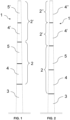
- each of said mounting groups (2, 2') comprises two stacked segments (4, 5, 4', 5'), the diameter or width of which decreases as the height increases.
- each of the segments (4, 5, 4', 5') in the tower (1) can be defined by the lifting height h i (i.e., the height at which the top end of each segment (4, 5, 4', 5') is installed in the tower (1) assembly); and by the lifting weight w i , which corresponds to the weight supported by a crane for lifting said segment (4, 5, 4', 5') up to the corresponding lifting height h i .
- the stacked segments (4, 5, 4', 5') will be respectively defined by four lifting heights h 4 , h 5 , h 4' , h 5' and their corresponding lifting weights w 4 , w 5 , w 4' , w 5' , which will in turn depend on the dimensions and manufacturing material of the segment (4, 5, 4', 5').
- both the base section (3) and the segments (4, 5, 4', 5') preferably have a characteristic length l i and a diameter d i .
- two threshold values H, H' for the jib height of said crane will be preset, with the corresponding maximum loads W, W allowed for said jib heights H, H', respectively. From said threshold values, it will be imposed on each of the segments (4, 5) of the first mounting group (2) (i.e., the group (2) installed immediately above the base (3) of the tower (1)) that the corresponding lifting heights h 4 , h 5 be smaller than or equal to the lowest of the preset jib threshold values (in the example of Figure 1 , it would correspond to a threshold value H, as defined above).
- the lifting heights (h 4' , h 5' ) corresponding to the respective segments (4', 5') will be required to be smaller than or equal to the highest of the preset jib threshold values (in the example, it would correspond to a threshold value H').
- the lifting weights (w 4 , w 5 ) corresponding to the segments (4, 5) of the first mounting segment (2) are equal to or smaller than the highest (W) of the jib load (or "counterweight") threshold values preset, such that they can be effectively lifted by the crane by means of the selected jib configuration. Accordingly, for the second stacked group (2') (i.e., the one arranged on the first group (2)), the lifting weights (w 4' , w 5' ) corresponding to the respective segments (4', 5') will be required to be smaller than or equal to the lowest (W) of the preset jib threshold values.
- each crane configuration is defined by its jib P length, the maximum lifting height H that can be reached with said jib length, and its corresponding maximum lifting weight W.
- the method of the invention can allow the number of stacked segments (4, 4', 5, 5') required in a tower (1) of a given height to be mounted with a given mounting crane model to be reduced, which translates into a higher mounting efficiency and speed by reducing the number of elements of the tower (1), with the corresponding cost reduction.
- the base section (3) and segments (4, 5, 4', 4") of the tower (1) it is possible to change such dimensions based on the particular requirements of each installation, required, for example, by the orographic, climate, or structural conditions of its location.
- the above-mentioned relationships referred to lifting heights h i and lifting weights w i must be verified in any of the embodiments used and, by using a distribution of lengths such as the one which characterizes the invention, this can be achieved by minimizing the number of crane configurations required.
- the base section (3) can have a length longer than the rest of the stacked segments (4, 5, 4', 4"). This achieves obtaining a more robust support structure of the tower (1) and reduces the weights of the stacked of the tower (1). More preferably, the length of the base section (3) exceeds by at least 50.0 cm the length of at least one of the stacked segments (4, 5, 4', 4") of said tower (1) segments (4, 5, 4', 4").
- the length of the stacked segment (4) arranged immediately above the base section (3) is equal to or smaller than the length of at least another stacked segment (5) in the same mounting group (2).
- the method of the invention can comprise the use of stacked segments (4, 5, 4', 4") formed by tubes made of metal and/or concrete both in a continuous manner and formed with voussoir joints.
- the combination of segments (4, 5, 4', 4") made of metal and of concrete is also possible.
- the stacked segments (4, 5, 4', 4") are formed by voussoirs, these will preferably be assembled at the base of the tower (1) to be installed in the assembly.
- the base section (3) can also be constructed as a continuous element or as a plurality of voussoirs, and the material for manufacturing it will preferably comprise concrete.
- the method for installing the present invention is preferably applied to towers (1) of heights equal to or greater than 100.0 m, for which the reduction of crane configurations represents a particularly valuable advantage.
- said towers comprise two mounting groups (2, 2'), wherein each group (2, 2') will comprise two stacked segments (4, 5, 4', 4").
- the top mounting group (2') comprises the nacelle and/or wind turbine blades.
- the crane used for installing the tower is a mobile type crane, for example with wheels or chains.
Landscapes
- Engineering & Computer Science (AREA)
- Architecture (AREA)
- Chemical & Material Sciences (AREA)
- Life Sciences & Earth Sciences (AREA)
- Mechanical Engineering (AREA)
- Civil Engineering (AREA)
- Combustion & Propulsion (AREA)
- General Engineering & Computer Science (AREA)
- Sustainable Development (AREA)
- Sustainable Energy (AREA)
- Structural Engineering (AREA)
- Materials Engineering (AREA)
- Wood Science & Technology (AREA)
- Jib Cranes (AREA)
- Electric Cable Installation (AREA)
- Gas-Insulated Switchgears (AREA)
- Suspension Of Electric Lines Or Cables (AREA)
- Input Circuits Of Receivers And Coupling Of Receivers And Audio Equipment (AREA)
Applications Claiming Priority (2)
| Application Number | Priority Date | Filing Date | Title |
|---|---|---|---|
| ES202130921A ES2938008B2 (es) | 2021-10-01 | 2021-10-01 | Procedimiento de instalacion de una torre y torre instalada con dicho procedimiento |
| PCT/ES2022/070617 WO2023052668A1 (es) | 2021-10-01 | 2022-09-29 | Procedimiento de instalación de una torre y torre instalada con dicho procedimiento |
Publications (2)
| Publication Number | Publication Date |
|---|---|
| EP4411091A1 true EP4411091A1 (de) | 2024-08-07 |
| EP4411091A4 EP4411091A4 (de) | 2025-10-29 |
Family
ID=85772178
Family Applications (1)
| Application Number | Title | Priority Date | Filing Date |
|---|---|---|---|
| EP22875243.2A Pending EP4411091A4 (de) | 2021-10-01 | 2022-09-29 | Verfahren zur installation eines turms und mit diesem verfahren installierter turm |
Country Status (4)
| Country | Link |
|---|---|
| US (1) | US20240401570A1 (de) |
| EP (1) | EP4411091A4 (de) |
| ES (1) | ES2938008B2 (de) |
| WO (1) | WO2023052668A1 (de) |
Family Cites Families (14)
| Publication number | Priority date | Publication date | Assignee | Title |
|---|---|---|---|---|
| US6955025B2 (en) * | 2002-09-11 | 2005-10-18 | Clipper Windpower Technology, Inc. | Self-erecting tower and method for raising the tower |
| ES1058539Y (es) * | 2004-10-11 | 2005-04-01 | Inneo21 S L | Estructura perfeccionada de torre modular para turbinas eolicas y otras aplicaciones. |
| ES2326010B2 (es) * | 2006-08-16 | 2011-02-18 | Inneo21, S.L. | Estructura y procedimiento de montaje de torres de hormigon para turbinas eolicas. |
| ES2350135B2 (es) * | 2008-07-04 | 2012-10-25 | Structural Concrete & Steel, S.L | Sistema de conexion para torres mixtas de aerogeneradores |
| DK2846040T3 (en) * | 2013-09-06 | 2018-05-22 | youWINenergy GmbH | Tower unit for a wind turbine installation |
| US9845612B2 (en) * | 2015-06-26 | 2017-12-19 | General Electric Company | System and method for assembling tower sections of a wind turbine lattice tower structure |
| EP3379078A1 (de) * | 2017-03-23 | 2018-09-26 | Nordex Energy GmbH | Verfahren und vorrichtung zur montage eines turms für eine windenergieanlage und turm einer windenergieanlage |
| DE102017009984A1 (de) * | 2017-10-26 | 2019-05-02 | Senvion Gmbh | Turm mit konischen Stahladapterelementen |
| DK3670899T3 (da) * | 2018-12-21 | 2024-05-27 | Nordex Energy Spain Sau | Fremgangsmåde til samling af en vindmølle og vindmølle samlet på grundlag af fremgangsmåden |
| DK3828121T3 (da) * | 2019-11-26 | 2024-05-06 | General Electric Renovables Espana Sl | Kran og fremgangsmåde til at rejse et tårn |
| ES1241584Y (es) * | 2020-01-16 | 2020-07-30 | Nordex Energy Spain Sau | Torre eolica |
| US11754048B2 (en) * | 2021-03-25 | 2023-09-12 | National Oilwell Varco, L.P. | Tower erection system |
| EP4555211A1 (de) * | 2022-07-15 | 2025-05-21 | CLS Wind LLC | Interferenzfreies stapelbares system für windturbinenturm |
| WO2025132092A2 (en) * | 2023-12-21 | 2025-06-26 | Itrec B.V. | Self climbing tower crane |
-
2021
- 2021-10-01 ES ES202130921A patent/ES2938008B2/es active Active
-
2022
- 2022-09-29 EP EP22875243.2A patent/EP4411091A4/de active Pending
- 2022-09-29 WO PCT/ES2022/070617 patent/WO2023052668A1/es not_active Ceased
- 2022-09-29 US US18/697,258 patent/US20240401570A1/en active Pending
Also Published As
| Publication number | Publication date |
|---|---|
| WO2023052668A1 (es) | 2023-04-06 |
| EP4411091A4 (de) | 2025-10-29 |
| US20240401570A1 (en) | 2024-12-05 |
| ES2938008A1 (es) | 2023-04-03 |
| ES2938008B2 (es) | 2024-04-16 |
Similar Documents
| Publication | Publication Date | Title |
|---|---|---|
| EP2541047B1 (de) | Verfahren zum Zusammenbau einer Windturbine und Windturbine, die nach diesem Verfahren zusammengebaut wird | |
| US20090031639A1 (en) | Pre-stressed concrete tower for wind power generators | |
| US20100162652A1 (en) | Segment for a Tower, Tower Constructed from Tower Segments, Element for a segment for a Tower, Method for the Pre-Assembly of segments for a Tower, Method for the Assembly of a Tower Containing Segments | |
| CN1918349A (zh) | 用于风轮机的塔、在风轮机的塔中使用的预制金属壁部分以及构建风轮机的塔的方法 | |
| EP3670899B1 (de) | Verfahren zur montage einer windturbine und nach dem verfahren zusammengesetzte windturbine | |
| CN102207059A (zh) | 风力涡轮机、塔架及其制造方法 | |
| EP3211154B1 (de) | Herstellungsprocess für windradmasten aus beton | |
| EP2574772B1 (de) | Windturbinen-Turm | |
| EP4442994A2 (de) | Verfahren zum transport eines windenergieanlagenturms | |
| US20100005731A1 (en) | Tower and wind turbine supporting structures and method for mounting the latter | |
| EP4411091A1 (de) | Verfahren zur installation eines turms und mit diesem verfahren installierter turm | |
| US20250347266A1 (en) | Wind turbine tower non-interference stackable system | |
| WO2010061048A1 (en) | Arrangement and method for erecting tower of wind power plant | |
| CN106545471B (zh) | 塔筒的建造施工方法 | |
| EP4617489A1 (de) | Hybrider windturbinenturm | |
| EP4230825A1 (de) | Turmverbinder | |
| US12467433B2 (en) | Wind power generation system | |
| EP4530422A1 (de) | Betonsegment eines abschnitts eines windturbinenturms, form zum giessen eines betonsegments | |
| CN221988035U (zh) | 一种基于塔吊标准节的模块化吊装临时支撑架 | |
| EP4363713B1 (de) | Übergangsstück für einen hybridwindturbinenturm und verfahren zur montage davon | |
| CN113494425B (zh) | 塔架及塔架构件 | |
| EP4495327A1 (de) | Positioniervorrichtung zum ausrichten mindestens eines nachspannelements in einem betonfundament | |
| EP3246493A1 (de) | Verfahren zur konstruktion eines mastes für eine windmühle | |
| AU2023348084A1 (en) | Concrete segment of a section of a tower of a wind turbine and adapter of a tower of a wind turbine tower | |
| CA3269053A1 (en) | Concrete segment of a section of a tower of a wind turbine and adapter of a tower of a wind turbine tower |
Legal Events
| Date | Code | Title | Description |
|---|---|---|---|
| STAA | Information on the status of an ep patent application or granted ep patent |
Free format text: STATUS: THE INTERNATIONAL PUBLICATION HAS BEEN MADE |
|
| PUAI | Public reference made under article 153(3) epc to a published international application that has entered the european phase |
Free format text: ORIGINAL CODE: 0009012 |
|
| STAA | Information on the status of an ep patent application or granted ep patent |
Free format text: STATUS: REQUEST FOR EXAMINATION WAS MADE |
|
| 17P | Request for examination filed |
Effective date: 20240404 |
|
| AK | Designated contracting states |
Kind code of ref document: A1 Designated state(s): AL AT BE BG CH CY CZ DE DK EE ES FI FR GB GR HR HU IE IS IT LI LT LU LV MC MK MT NL NO PL PT RO RS SE SI SK SM TR |
|
| DAV | Request for validation of the european patent (deleted) | ||
| DAX | Request for extension of the european patent (deleted) | ||
| A4 | Supplementary search report drawn up and despatched |
Effective date: 20250926 |
|
| RIC1 | Information provided on ipc code assigned before grant |
Ipc: E04H 12/12 20060101AFI20250922BHEP Ipc: B66C 23/18 20060101ALI20250922BHEP Ipc: F03D 13/20 20160101ALI20250922BHEP Ipc: F03D 13/10 20160101ALI20250922BHEP |