EP4410660A1 - Plate, boat propulsor with a plate and boat with boat propulsor - Google Patents
Plate, boat propulsor with a plate and boat with boat propulsor Download PDFInfo
- Publication number
- EP4410660A1 EP4410660A1 EP23206050.9A EP23206050A EP4410660A1 EP 4410660 A1 EP4410660 A1 EP 4410660A1 EP 23206050 A EP23206050 A EP 23206050A EP 4410660 A1 EP4410660 A1 EP 4410660A1
- Authority
- EP
- European Patent Office
- Prior art keywords
- duct
- plate
- boat
- propulsor
- holes
- Prior art date
- Legal status (The legal status is an assumption and is not a legal conclusion. Google has not performed a legal analysis and makes no representation as to the accuracy of the status listed.)
- Pending
Links
- 230000007246 mechanism Effects 0.000 claims abstract description 8
- 238000000926 separation method Methods 0.000 claims description 10
- XLYOFNOQVPJJNP-UHFFFAOYSA-N water Substances O XLYOFNOQVPJJNP-UHFFFAOYSA-N 0.000 abstract description 25
- 230000009467 reduction Effects 0.000 abstract description 17
- 230000002238 attenuated effect Effects 0.000 abstract description 5
- 230000009471 action Effects 0.000 description 5
- 238000011144 upstream manufacturing Methods 0.000 description 3
- 229910000838 Al alloy Inorganic materials 0.000 description 2
- 238000005516 engineering process Methods 0.000 description 2
- 229910052751 metal Inorganic materials 0.000 description 2
- 239000002184 metal Substances 0.000 description 2
- 238000000034 method Methods 0.000 description 2
- 230000005540 biological transmission Effects 0.000 description 1
- 238000002485 combustion reaction Methods 0.000 description 1
- 230000001419 dependent effect Effects 0.000 description 1
- 230000000694 effects Effects 0.000 description 1
- 238000004519 manufacturing process Methods 0.000 description 1
- 230000004048 modification Effects 0.000 description 1
- 238000012986 modification Methods 0.000 description 1
- 238000003466 welding Methods 0.000 description 1
Images




Classifications
-
- B—PERFORMING OPERATIONS; TRANSPORTING
- B63—SHIPS OR OTHER WATERBORNE VESSELS; RELATED EQUIPMENT
- B63H—MARINE PROPULSION OR STEERING
- B63H1/00—Propulsive elements directly acting on water
- B63H1/02—Propulsive elements directly acting on water of rotary type
- B63H1/12—Propulsive elements directly acting on water of rotary type with rotation axis substantially in propulsive direction
- B63H1/14—Propellers
- B63H1/28—Other means for improving propeller efficiency
-
- B—PERFORMING OPERATIONS; TRANSPORTING
- B63—SHIPS OR OTHER WATERBORNE VESSELS; RELATED EQUIPMENT
- B63H—MARINE PROPULSION OR STEERING
- B63H20/00—Outboard propulsion units, e.g. outboard motors or Z-drives; Arrangements thereof on vessels
- B63H20/32—Housings
- B63H20/34—Housings comprising stabilising fins, foils, anticavitation plates, splash plates, or rudders
-
- B—PERFORMING OPERATIONS; TRANSPORTING
- B63—SHIPS OR OTHER WATERBORNE VESSELS; RELATED EQUIPMENT
- B63H—MARINE PROPULSION OR STEERING
- B63H5/00—Arrangements on vessels of propulsion elements directly acting on water
- B63H5/07—Arrangements on vessels of propulsion elements directly acting on water of propellers
-
- B—PERFORMING OPERATIONS; TRANSPORTING
- B63—SHIPS OR OTHER WATERBORNE VESSELS; RELATED EQUIPMENT
- B63H—MARINE PROPULSION OR STEERING
- B63H5/00—Arrangements on vessels of propulsion elements directly acting on water
- B63H5/07—Arrangements on vessels of propulsion elements directly acting on water of propellers
- B63H5/16—Arrangements on vessels of propulsion elements directly acting on water of propellers characterised by being mounted in recesses; with stationary water-guiding elements; Means to prevent fouling of the propeller, e.g. guards, cages or screens
-
- B—PERFORMING OPERATIONS; TRANSPORTING
- B63—SHIPS OR OTHER WATERBORNE VESSELS; RELATED EQUIPMENT
- B63H—MARINE PROPULSION OR STEERING
- B63H20/00—Outboard propulsion units, e.g. outboard motors or Z-drives; Arrangements thereof on vessels
- B63H20/08—Means enabling movement of the position of the propulsion element, e.g. for trim, tilt or steering; Control of trim or tilt
- B63H20/12—Means enabling steering
-
- B—PERFORMING OPERATIONS; TRANSPORTING
- B63—SHIPS OR OTHER WATERBORNE VESSELS; RELATED EQUIPMENT
- B63H—MARINE PROPULSION OR STEERING
- B63H20/00—Outboard propulsion units, e.g. outboard motors or Z-drives; Arrangements thereof on vessels
- B63H2020/003—Arrangements of two, or more outboard propulsion units
-
- B—PERFORMING OPERATIONS; TRANSPORTING
- B63—SHIPS OR OTHER WATERBORNE VESSELS; RELATED EQUIPMENT
- B63H—MARINE PROPULSION OR STEERING
- B63H5/00—Arrangements on vessels of propulsion elements directly acting on water
- B63H5/07—Arrangements on vessels of propulsion elements directly acting on water of propellers
- B63H5/125—Arrangements on vessels of propulsion elements directly acting on water of propellers movably mounted with respect to hull, e.g. adjustable in direction, e.g. podded azimuthing thrusters
-
- B—PERFORMING OPERATIONS; TRANSPORTING
- B63—SHIPS OR OTHER WATERBORNE VESSELS; RELATED EQUIPMENT
- B63H—MARINE PROPULSION OR STEERING
- B63H5/00—Arrangements on vessels of propulsion elements directly acting on water
- B63H5/07—Arrangements on vessels of propulsion elements directly acting on water of propellers
- B63H5/14—Arrangements on vessels of propulsion elements directly acting on water of propellers characterised by being mounted in non-rotating ducts or rings, e.g. adjustable for steering purpose
Definitions
- the present invention relates to a plate configured to be provided at a duct of a boat propulsor, a boat propulsor with a plate and a boat with a boat propulsor.
- Duct-type boat propulsors are known.
- a duct-type boat propulsor has a duct, a propeller disposed in the duct and rotatable around a rotation axis along the axial direction of the duct, and a rotation mechanism to rotate the propeller (see, e.g., JP Utility Model Application Publication No. JP 2016-068610A , JP 2013-100013A , JP 2013-100014A , JP 2022-018645A ).
- the generation of a large vortex engulfing the air entering the duct can affect the maneuverability of the hull such as making it impossible to move laterally.
- a large vortex engulfing the air entering the duct
- the sink vortex can affect the maneuverability of the hull, causing the hull to move diagonally sideways despite the maneuvering command to move the hull laterally.
- a plate configured to be provided at a duct of a boat propulsor having the features of independent claim 1, a boat propulsor with a plate according to claim 7 and a boat with a boat propulsor according to claim 14.
- Preferred embodiments are laid down in the dependent claims.
- a boat propulsor disclosed herein includes a duct, a propeller disposed in the duct and rotatable around a rotation axis along the axial direction of the duct, and a rotation mechanism to rotate the propeller.
- the upper portion of the duct is provided with a plate extending from the duct in the axial direction and having a plurality of holes formed therein.
- the plate is provided to extend from the upper portion of the duct, and the plate is provided with a plurality of holes formed therein. Multiple water streams coming around along the duct are attenuated as they pass through the holes in the plate.
- the present boat propulsor can suppress the reduction in maneuverability of the hull caused by the sink vortex generated in the vicinity of the duct.
- the lowest end of the plate may be configured to be located above the rotation axis.
- this boat propulsor can reduce the weight of the boat propulsor while suppressing the reduction in maneuverability of the hull caused by the sink vortex.
- the plate may be configured to be symmetrical with respect to the rotation axis when viewed in the upper-lower direction. According to this boat propulsor, compared to a configuration in which the plate is asymmetrically shaped, it is possible to suppress the boat propulsor from being subjected to unequal left-right forces due to left-right flow variations in the vicinity of the duct.
- the plate may be configured to be curved along the circumferential direction of the duct. According to this boat propulsor, compared to a configuration in which the plate is flat, the plate does not disturb the wing-like connection of the duct and also has excellent attachability to the duct, as well as suppressing the reduction in maneuverability of the hull caused by the sink vortex.
- the plurality of holes may be configured to include a plurality of slits extending along the axial direction of the duct. According to this boat propulsor, compared to a configuration in which the holes are slits extending in a direction that intersects the axial direction of the duct, it is possible to suppress the existence of the holes from becoming a resistance element to the maneuverability of the hull.
- the plurality of holes may be configured to be arranged symmetrically with respect to the rotation axis when viewed in the upper-lower direction. According to this boat propulsor, it is possible to suppress the boat propulsor from being subjected to unequal left-right forces due to variations in the arrangement of the plurality of holes.
- the separation distance between two mutually adjacent holes may be configured to be wider than the opening width of each hole in the alignment direction of the two holes. According to this boat propulsor, vortices dispersed by two adjacent holes can merge again after passing through each hole to form a large vortex, thereby suppressing the reduction in maneuverability of the hull.
- the plate may be configured to be a part separate from the duct, and the plate may be configured to be fixed to the outer surface of the duct at a first fixing position and a second fixing position that is displaced from the first fixing position in both the axial and circumferential directions of the duct.
- this boat propulsor can improve the strength of the plate against the downward force due to the sink vortex.
- a boat disclosed herein may be configured to include a hull and a boat propulsor according to any one of (1) to (8) above. This boat can suppress the reduction in maneuverability of the hull caused by the sink vortex generated in the vicinity of the duct.
- a plate disclosed herein is provided so as to extend axially from an upper portion of a duct of a boat propulsor wherein a propeller is disposed in the duct and rotatable about a rotation axis along the axial direction of the duct.
- the plate is provided with a plurality of holes formed therein. This plate can suppress the reduction in maneuverability of the hull caused by the sink vortex generated in the vicinity of the duct.
- the above plate may be configured to be symmetrical in shape when viewed in the upper-lower direction. According to this plate, for example, compared to a configuration in which the plate is asymmetrically shaped, it is possible to suppress the boat propulsor from being subjected to unequal left-right forces due to left-right flow variations in the vicinity of the duct.
- the above plate may be configured to be curved. According to this plate, compared to a configuration in which the plate is flat, the plate does not disturb the wing-like connection of the duct and also has excellent attachability to the duct, as well as suppressing the reduction in maneuverability of the hull caused by the sink vortex.
- the plurality of holes may be configured to include a plurality of slits extending along a predetermined direction. According to this plate, for example, compared to a configuration in which a plurality of slits extend in different directions from each other, it is possible to suppress the existence of the holes from becoming a resistance element to the maneuverability of the hull.
- the plurality of holes may be configured to be arranged symmetrically when viewed in the upper-lower direction. This plate can suppress the boat propulsor from being subjected to unequal left-right forces due to variations in the arrangement of the plurality of holes.
- the separation distance between two mutually adjacent holes may be configured to be wider than the opening width of each hole in the alignment direction of the two holes.
- the technology disclosed herein can be implemented in various forms, such as in the form of a boat, a boat propulsor provided on the boat, a plate provided on the boat propulsor, and a method for suppressing a sink vortex toward a duct.
- the boat propulsor disclosed herein can suppress the reduction in maneuverability of the hull caused by the sink vortex generated in the vicinity of the duct.
- FIG. 1 is a simplified top view illustrating a configuration of a boat 10 in an embodiment
- FIG. 2 is a simplified side view illustrating a configuration of the leading edge of the boat 10.
- FIGS. 1 and 2 show arrows representing each direction with respect to the position of the boat 10. More specifically, each drawing shows arrows representing the front direction (FRONT), rear direction (REAR), left direction (LEFT), right direction (RIGHT), upper direction (UPPER), and lower direction (LOWER), respectively.
- the front-rear direction, left-right direction, and upper-lower (vertical) direction are orthogonal to each other.
- the boat 10 includes a hull 200, a boat propulsion system (hereinafter referred to as the "propulsion system") 100 mounted on the hull 200, a first plate 300 (see, e.g., FIG. 3 below) and a second plate 350 (see FIG. 7 below).
- the propulsion system hereinafter referred to as the "propulsion system”
- first plate 300 see, e.g., FIG. 3 below
- second plate 350 see FIG. 7 below.
- the hull 200 is a part of the boat 10 for occupants to ride.
- the hull 200 includes, e.g., a hull main body having a living space, a pilot seat (not shown) installed in the living space, and an operating device (not shown) installed near the pilot seat.
- the propulsion system 100 includes a plurality of electric propulsors 110, a bow thruster 150 provided separately from the electric propulsors 110, and a boat control device (not shown) that controls them.
- the electric propulsor 110 is an example of the boat propulsor in the claims.
- FIG. 1 shows a duct 122, a stator fin 133, and a bearing 135 of the electric propulsor 110, and a propeller 154 of the bow thruster 150, all of which will be described later.
- the electric propulsor 110 is a device that generates thrust to propel the boat 10.
- Each electric propulsor 110 is provided at the stern 202 of the hull 200 and is designed to exert propulsion force on the hull 200 behind the instantaneous turning center P of the hull 200.
- the plurality of electric propulsors 110 include the left-side electric propulsor 110 (the electric propulsor 110 on the left side in FIG. 1 ) and the right-side electric propulsor 110 (the electric propulsor 110 on the right side in FIG. 1 ).
- the left-side electric propulsor 110 and the right-side electric propulsor 110 are arranged symmetrically with respect to the center line C of the hull 200.
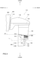
- FIG. 3 is a simplified side view illustrating a configuration of the electric propulsor 110.
- each electric propulsor 110 includes a propulsor body 112 and a bracket 114.
- the propulsor body 112 is attached to the stern 202 of the hull 200 via the bracket 114.
- the propulsor body 112 includes a cover 116, a base 118, a housing 120, a duct 122, and a drive unit 130.
- the base 118 is connected to the bracket 114.
- the cover 116 covers the upper portion of the bracket 114.
- the housing 120 is disposed below the base 118.
- the housing 120 extends downward from the base 118.
- the duct 122 is disposed below the housing 120.
- the duct 122 is tubular in shape.
- the duct 122 is disposed at a position below the water surface W (see FIG. 3 ).
- the drive unit 130 is disposed in the duct 122.
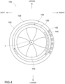
- FIG. 4 is a schematic view illustrating a configuration of the drive unit 130.
- the drive unit 130 generates thrust that propels the boat 10.
- the drive unit 130 includes a propeller 132 and an electric motor 134.
- the electric motor 134 is an example of the rotation mechanism in the claims.
- the propeller 132 is a rotating body having a plurality of blades and generates thrust by rotating.
- the propeller 132 is provided inside the duct 122 and is rotatable around a horizontal propeller rotation axis L (see FIG. 4 ).
- the propeller rotation axis L is parallel to the central axis of the duct 122.
- the duct 122 covers the entire circumference of the propeller 132, and the ducting effect of the duct 122 increases the velocity of water flowing into the duct 122.
- the duct 122 is an example of the duct in the claims.
- the electric motor 134 rotates the propeller 132.
- the electric motor 134 includes a rotor 136 and a stator 138.
- the rotor 136 and the stator 138 each have a tubular shape.
- the rotor 136 is disposed radially inward of the stator 138.
- the rotor 136 and the stator 138 are disposed on the same axis.
- the rotor 136 is rotatably supported against the duct 122.
- the rotor 136 rotates about the propeller rotation axis L with respect to the stator 138.
- the propeller 132 is disposed radially inward of the rotor 136.
- the propeller 132 is fixed to the rotor 136 and rotates together with the rotor 136.
- the rotor 136 includes a plurality of permanent magnets 140.
- the plurality of permanent magnets 140 are disposed along the circumferential direction of the rotor 136. In FIG. 4 , only one of the plurality of permanent magnets 140 is labeled with the reference character "140", and the reference characters of the other permanent magnets 140 are omitted.
- the stator 138 is fixed to the duct 122.
- the stator 138 includes a plurality of coils 142.
- the plurality of coils 142 are disposed along the circumferential direction of the stator 138.
- an electromagnetic force is generated to rotate the rotor 136.
- FIG. 4 only one of the plurality of coils 142 is labeled with the reference character "142", and the reference characters of the other coils 142 are omitted.
- the propeller 132 generates forward propulsion force when the electric motor 134 rotates in the forward direction and backward propulsion force when the electric motor 134 rotates in the reverse direction.
- the housing 120 is rotatably mounted with respect to the base 118 around a steering axis (an axis along the vertical direction in each figure) as a vertical rotation axis.
- the drive unit 130 also rotates around the steering axis.
- the stator fin 133 and the bearing 135 are provided on the radial inner side of the duct 122.
- the bearing 135 supports the propeller 132 rotatably about the propeller rotation axis L.
- the stator fin 133 has a plurality of fins (e.g., three fins).
- the plurality of fins are arranged radially around the bearing 135 and equally spaced around the propeller rotation axis L and are fixed to the duct 122.
- the plurality of fins are provided behind the propeller 132, projecting backward from the duct 122 (see FIGS. 1 and 3 ).
- the bow thruster 150 is disposed at a position in the hull 200 in the vicinity of the bow 204 and lower than the water surface W.
- the bow thruster 150 is a propulsor that provides lateral propulsion force to the hull 200.
- the bow thruster 150 includes a duct 152, a propeller 154, and an electric motor (not shown).
- the duct 152 is a tubular body that penetrates in the left-right direction and is attached to the hull 200 via a bracket 156.
- the propeller 154 is a rotating body having a plurality of blades and generates thrust by rotating.
- the propeller 154 is provided inside the duct 152 in the radial direction and is rotatable around the propeller rotation axis M in the left-right direction.
- the electric motor has the same configuration as the electric motor 134 described above and is disposed in the duct 152.
- the propeller 154 is rotated by the power generated by the electric motor. Specifically, the propeller 154 generates propulsion force to the right when the electric motor rotates in the forward direction and to the left when the electric motor rotates in the reverse direction.
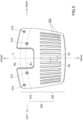
- FIG. 5 is a top view illustrating a configuration of a first plate 300
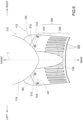
- FIG. 6 is a top view illustrating the first plate 300 in a state attached to the duct 122.
- the first plate 300 is attached to the duct 122 of the electric propulsor 110 (see, e.g., FIG. 3 ) and serves to attenuate the vorticity of the sink vortex generated by the multiple water flows that occur near the duct 122.
- the first plate 300 is a part separate from the duct 122.
- the first plate 300 is provided in the upper portion of the duct 122 and extends from the duct 122 in a direction along the propeller rotation axis L.
- the first plate 300 is provided with a plurality of holes 322 formed therein.
- the first plate 300 is, as a whole, a substantially rectangular flat plate.
- the first plate 300 is formed of a metal such as an aluminum alloy.
- the entire first plate 300 has a uniform thickness.
- the first plate 300 is curved along the circumferential direction of the duct 122 (see FIGS. 3 , 5 , and 6 ).
- the first plate 300 is curved around the propeller rotation axis L.
- the first plate 300 projects from the upper portion of the duct 122 along the propeller rotation axis L.
- the lowest end of the first plate 300 is located above the propeller rotation axis L (see FIG. 3 ).
- the total circumferential length of the first plate 300 is a length corresponding to 120 degrees (1/3) with respect to the total circumference of the duct 122.
- the overall length of the first plate 300 is preferably no less than a length corresponding to 90 degrees (1/4) and no more than a length corresponding to 180 degrees (1/2) with respect to the entire circumference of the duct 122.
- the first plate 300 is symmetrical with respect to the propeller rotation axis L when viewed in the upper-lower direction (see FIGS. 5 and 6 ).
- the first plate 300 has the fixing portion 310 and the protruding portion 320.
- the protruding end of the protruding portion 320 is preferably located behind the rear end of the housing 120 (see FIG. 3 ). If the diameter of the propeller 132 is supposed to be "N" (e.g., 280 mm), the length of the first plate 300 protruding from the rear end of the duct 122 (length of the protruding portion 320) may be 0.25N or more, or 0.4N or more. The length of the protruding portion 320 may be 0.75D or less, or 0.6N or less.
- the fixing portion 310 is the portion of the first plate 300 that is fixed to the duct 122.
- the fixing portion 310 is the front portion including the front end in the first plate 300 and is fixed to the outer circumference of the duct 122.
- the fixing portion 310 is curved in shape corresponding to the outer circumferential surface of the duct 122. Therefore, the inner surface of the fixing portion 310 is in surface contact with the outer circumferential surface of the duct 122 over the entire circumferential length of the fixing portion 310.
- the fixing portion 310 is fixed to the outer circumferential surface of the duct 122 at first fixing positions 312 and second fixing positions 314 (see FIGS. 5 and 6 ).
- the first fixing position 312 and the second fixing position 314 are displaced from each other in the direction along the propeller rotation axis L of the duct 122 as well as in the circumferential direction of the duct 122.
- the first fixing positions 312 are respectively arranged symmetrically with respect to L when viewed in the upper-lower direction.
- the second fixing positions 314 are respectively arranged symmetrically with respect to L when viewed in the upper-lower direction.
- Each first fixing position 312 is positioned closer to the propeller rotation axis L than the second fixing position 314 when viewed in the upper-lower direction.
- Each first fixing position 312 is positioned on a first virtual circle R1 centered on the propeller rotation axis L.
- Each second fixing position 314 is located on a second virtual circle R2 centered on the propeller rotation axis L.
- the second virtual circle R2 is located closer to the front end of the first plate 300 (fixing portion 310) than the first virtual circle R1.
- the first plate 300 is fixed to the duct 122 by a fastening member (such as bolts) not shown.
- the protruding portion 320 is a portion of the first plate 300 that protrudes from the duct 122 in a direction along the propeller rotation axis L (rear side of the duct 122).
- the protruding portion 320 is provided with a plurality of holes 322 formed therein. All holes 322 are slits extending along the propeller rotation axis L.
- the opening width D1 of the slits (see FIG. 5 ) is substantially identical over the entire length of the slits.
- the slit can be a closed hole that is closed all the way around, as shown in, e.g., FIG. 5 , or it can be an open hole that is partially open (e.g., at the rear end side of the first plate 300).
- all holes 322 are of the same shape and size as each other and are arranged at equal intervals (see separation distance D2 in FIG. 3 ) in the circumferential direction of the duct 122.
- the separation distance D2 is substantially identical over the entire length of the slit.
- All holes 322 are arranged symmetrically with respect to the propeller rotation axis L when viewed in the upper-lower direction (see FIGS. 5 and 6 ).
- a plurality (equal number) of holes 322 are formed on the right side and the left side, respectively, with respect to the propeller rotation axis L.
- the separation distance D2 between two holes 322 (slits) adjacent to each other is wider than the opening width D1 of each hole in the alignment direction of the two holes 322 (circumferential direction of the duct 122) (see FIG. 5 ).
- all holes 322 satisfy all of the following conditions (1) to (5).
- FIG. 7 is a front view illustrating a configuration of a second plate 350.
- the second plate 350 is attached to the duct 152 of the bow thruster 150 and serves to attenuate the vorticity of the sink vortex generated by the multiple water streams near the duct 152.
- the second plate 350 is a part separate from the duct 152.
- the second plate 350 is provided in the upper portion of the duct 152 and extends from the duct 152 in a direction along the propeller rotation axis M.
- the second plate 350 is provided with a plurality of holes 352 formed therein.
- the second plate 350 is, as a whole, a substantially rectangular flat plate.
- the second plate 350 is formed of a metal such as an aluminum alloy.
- the entire second plate 350 has a uniform thickness.
- the second plate 350 is curved along the circumferential direction of the duct 152.
- the second plate 350 is curved around the propeller rotation axis M.
- the second plate 350 has a fixing portion 360 and a pair of protruding portions 370.
- the fixing portion 360 is the portion of the second plate 350 that is fixed to the duct 152.
- the pair of protruding portions 370 are portions of the second plate 350 respectively protruding from the duct 152 in the direction along the propeller rotation axis M (on either side of the duct 152).
- Each protruding portion 370 is provided with a plurality of holes 352 formed therein. All holes 352 are slits extending along the propeller rotation axis M. All holes 352 are equally spaced in the circumferential direction of the duct 152.
- the boat 10 can move not only forward and backward but also laterally.
- the lateral movement is a translational movement in which the hull 200 is moved in a direction that includes a left-right component (e.g., to the right or to the right-diagonally backward) while maintaining the longitudinal orientation without turning the hull 200.
- the boat 10 is moved laterally by using the propulsion force of the bow thruster 150 in addition to the electric propulsor 110.
- the boat 10 may be configured to move laterally without using the propulsion force of the bow thruster 150.
- FIG. 1 illustrates the boat 10 moving laterally in the right direction.
- the left propulsion force FL from the left-side electric propulsor 110 and the right-directional propulsion force FR from the right-side electric propulsor 110 generate a right-directional propulsion force F1.
- the orientation of each electric propulsor 110 is adjusted so that the left action line DL of the left propulsion force FL and the right action line DR of the right-directional propulsion force FR cross each other on the front side of the electric propulsor 110.
- each action line DL, DR is inclined with respect to the center line C of the hull 200.
- the left-side electric propulsor 110 and the right-side electric propulsor 110 rotate the propellers 132 in opposite directions.
- the combined force of the left propulsion force FL and the right-directional propulsion force FR is generated at the intersection position X of the left action line DL and the right action line DR as the right-directional propulsion force F1.
- the right-directional propulsion force F2 is generated by the bow thruster 150 in this configuration. Therefore, a propulsion force F3, which is the combined force of the right-directional propulsion force F1 and the right-directional propulsion force F2, is generated in the hull 200, causing the hull 200 to move laterally.
- the magnitudes of the propulsion force F1 and F2 are set so that the yawing moment about the turning center P due to the propulsion force F1 (hereinafter referred to as "moment") cancels the moment about the turning center P due to the propulsion force F2.
- the output of the electric propulsor 110 and bow thruster 150 is controlled according to the amount of operation at the operation device. Specifically, the boat control device sets the target value of the propulsion force F3, the hull target value, according to the amount of operation at the operation device.
- FIG. 8 is an explanatory view schematically illustrating the water streams near the duct 122 without the first plate 300
- FIG. 9 is an explanatory view schematically illustrating the water streams near the duct 122 with the first plate 300.
- a large vortex (hereinafter referred to as a "sink vortex S1”) may be generated that engulfs the air S3 toward the duct 122.
- a large vortex (hereinafter referred to as a "sink vortex S1”) that engulfs the air S3 toward the duct 122.
- the propeller 132 is rotated in the water, multiple water streams S2 that flow around along the duct 122 merge and grow into a large vortex (the "sink vortex S1”) that engulfs the air S3 near the water surface W.
- the propulsion force of the electric propulsor 110 (see arrow FRa) is considered to fluctuate due to the fluctuating thrust of the propeller 132.
- the fluctuation of the propulsion force of the electric propulsor 110 is particularly pronounced.
- the sink vortex S1 tends to occur especially on the upstream side of the duct 122 in the right-side electric propulsor 110 (upstream side of the water stream flowing through the duct 122 due to the rotation of the propeller 132, or behind the duct 122 on the right side in FIG. 1 ).
- the sink vortex S1 is comparatively less likely to occur on the upstream side of the duct 122 in the left-side electric propulsor 110 (in front of the left-side duct 122 in FIG. 1 ).
- the hull 200 exists in front of the left-side duct 122 so that multiple water streams S2 that come around along the duct 122 are dispersed due to interference with the hull 200. If the right-directional propulsion force FRa by the right-side electric propulsor 110 is reduced due to the generation of the sink vortex S1 behind the right-side duct 122, the combined force of the left propulsion force FL and the right-directional propulsion force FRa becomes the right-diagonal forward propulsion force Fa (see FIG. 1 ).
- the combined force of the right-diagonal forward propulsion force Fa generated by the electric propulsor 110 and the right-directional propulsion force F2 generated by the bow thruster 150 becomes the right-diagonal forward propulsion force Fb, making it impossible to move the boat 10 laterally with good accuracy.
- the boat 10 of the present embodiment can attenuate the vorticity of the sink vortex S1 generated on the rear side of the duct 122 of the right-side electric propulsor 110 because the first plate 300 is attached to the duct 122 of the right-side electric propulsor 110. That is, the first plate 300 is provided on the upper portion of the duct 122 and extends from the duct 122 in a direction along the propeller rotation axis L. The first plate 300 is provided with a plurality of holes 322 formed therein. As shown in FIG. 9 , the multiple water streams S2 flowing around along the duct 122 reduce their vorticity (strength) as they pass through the holes 322 formed in the first plate 300.
- the vorticity of the sink vortex S1 generated by the multiple water streams S2 can be attenuated.
- the combined force of the left propulsion force FL and the right-directional propulsion force FR becomes the right-directional propulsion force F1 (see FIG. 1 ).
- the combined force of the right-directional propulsion force F1 generated by the electric propulsor 110 and the right-directional propulsion force F2 generated by the bow thruster 150 becomes the right-directional propulsion force F3, allowing the boat 10 to move laterally with high accuracy.
- the vorticity of the sink vortex S1 generated on the rear side of the duct 122 of the left-side electric propulsor 110 can be attenuated.
- a sink vortex can occur near the duct 122 of the electric propulsor 110.
- this embodiment can suppress the reduction in maneuverability of the hull 200 caused by the sink vortex because the first plate 300 is attached to the duct 122.
- the second plate 350 is attached to the duct 152 of the bow thruster 150 of the boat 10, the vorticity of the sink vortex S1 generated on the right and left sides of the duct 152 can be attenuated. As a result, it is possible to suppress the reduction in maneuverability of the hull 200 during lateral movement that would occur when the propulsion force F2 generated by the bow thruster 150 is reduced due to the generation of the sink vortex S1 near the duct 152.
- the lowest end of the first plate 300 is located above the propeller rotation axis L (see FIG. 3 ).
- this embodiment can reduce the weight of the electric propulsor 110 while suppressing the reduction in maneuverability of the hull 200 caused by the sink vortex.
- the first plate 300 is symmetrical with respect to the propeller rotation axis L when viewed in the upper-lower direction (see FIGS. 5 and 6 ).
- the electric propulsor 110 can be suppressed from being subjected to unequal left-right forces due to left-right flow variations in the vicinity of the duct 122.
- the first plate 300 is curved along the circumferential direction of the duct 122 (see FIGS. 3 , 5 , and 6 ).
- the first plate 300 does not disturb the wing-like connection of the duct 122 and also has excellent attachability to the duct 122, and the strength of the first plate 300 can be improved while suppressing the reduction in maneuverability of the hull 200 caused by the sink vortex.
- the first plate 300 is less likely to obstruct the flow of water along the duct 122. Therefore, it is possible to suppress the reduction in maneuverability of the hull 200 due to the presence of the first plate 300.
- the plurality of holes 322 formed in the first plate 300 are slits that extend along the propeller rotation axis L. Therefore, for example, compared to a configuration in which the holes 322 are slits extending in a direction that intersects the propeller rotation axis L, the holes 322 are less likely to obstruct the flow of water along the duct 122. Therefore, it is possible to suppress the reduction in maneuverability of the hull 200 due to the presence of the holes 322.
- the number of steps required for the manufacturing process of the plate can be reduced because fewer steps are required to open the holes.
- the plurality of holes 322 are arranged symmetrically with respect to the propeller rotation axis L when viewed in the upper-lower direction (see FIGS. 5 and 6 ). This can suppress the electric propulsor 110 from being subjected to uneven left-right forces, e.g., due to variations in the arrangement of the plurality of holes 322.
- the separation distance D2 between two holes 322 (slits) adjacent to each other is wider than the opening width D1 of each hole in the alignment direction of the two holes 322 (circumferential direction of the duct 122) (see FIG. 5 ). Therefore, the vortices dispersed by the 1/2 holes 322 adjacent to each other can merge again after the passage of each hole 322 to form a large vortex, and as a result, the reduction in maneuverability of the hull 200 during lateral movement can be suppressed.
- the fixing portion 310 is fixed to the outer surface of the duct 122 at a first fixing position 312 and a second fixing position 314 (see FIGS. 5 and 6 ).
- the first fixing position 312 and the second fixing position 314 are displaced from each other in the direction along the propeller rotation axis L of the duct 122 as well as in the circumferential direction of the duct 122.
- the strength of the first plate 300 against the downward force due to the sink vortex can be improved.
- the configuration of the boat 10, the boat propulsion system 100, and the plates 300, 350 in the above embodiment is only an example and can be modified in various ways.
- the boat propulsion system 100 is provided with a plurality of electric propulsors 110 and the bow thruster 150, but it may be configured with one or three or more electric propulsors 110 or without the bow thruster 150.
- the electric propulsor 110 is illustrated as the boat propulsor, but the boat propulsor may be an outboard motor, an inboard motor, an inboard/outboard motor, or a jet propulsor.
- the drive source for these outboard motors or the like may be an electric motor or an internal combustion engine.
- the electric propulsor 110 may also be configured without the stator fin 133.
- the bow thruster 150 located near the bow 204 of the hull 200 is illustrated as the boat propulsor, but the boat propulsor may be a side thruster located at a position other than the bow 204 (e.g., near the stern 202).
- the rotation mechanism may include a drive source provided outside the duct 122 and a transmission mechanism that transmits the power of the drive source to the propeller 132.
- the first plate 300 is a part separate from the duct 122.
- the first plate 300 may be configured as an integral part of the duct 122.
- the second plate 350 may be in a configuration integrally formed with the duct 152.
- the first plate 300 (protruding portion 320) is configured to be located at a position corresponding to the upper portion of the duct 122
- the first plate 300 may also be configured to be located over the entire circumference of the duct 122.
- the first plate 300 (protruding portion 320) need only be disposed at a position corresponding at least to the upper portion of the duct 122.
- the upper portion of the duct 122 is provided in the counterclockwise direction from 45 degrees or 60 degrees to 90 degrees with respect to a reference line (not shown) extending upwardly from the propeller rotation axis L of the duct 122 and in the clockwise direction from 45 degrees or 60 degrees to 90 degrees with respect to the reference line, for example.
- the holes 322 formed in the first plate 300 and the holes 352 formed in the second plate 350 as slits extending along the propeller rotation axis L.
- the holes can be slits intersecting (e.g., orthogonally intersecting) the propeller rotation axis L, triangular slits having an opening width wider toward the protruding end of the plate, or round holes or rectangular holes, among others.
- the plurality of holes 322, 352 formed in each plate 300, 350 may be of the same shape and size as each other but may also include a plurality of holes that differ from each other in at least one of shape and size, or may be arranged in an uneven pattern.
- the minimum opening width in each of the holes 322, 352 is preferably narrower than the separation distance from the nearest other hole (separation distance D2 described above) but may be equal to or wider than the separation distance.
- the minimum opening width in each hole 322, 352 is preferably wider than the thickness of each plate 300, 350 but may be narrower than the thickness of each plate 300, 350.
- at least some of the plurality of holes 322 formed in the first plate 300 may not satisfy at least some of the conditions in (1) to (5) described above.
- the first plate 300 is formed to have a curved shape. Alternatively, the plate may be formed flat as a whole. The right portion and left portion of the first plate 300 may be asymmetrical in shape relative to the propeller rotation axis L when viewed in the upper-lower direction.
- the fixing portion 310 of the first plate 300 may be fixed to the duct 122 by a fixing method (e.g., welding) other than the fastening member mentioned above.
- the fixing portion 310 may be fixed to the inner surface side of the duct 122.
- the protruding portion 320 of the first plate 300 may be provided to protrude not only to the rear side of the duct 122 but also to the front side of the duct 122.
- the second plate 350 (protruding portion 370) is configured to be located at a position corresponding to the upper portion of the duct 152
- the second plate 350 may also be configured to be located over the entire circumference of the duct 152.
- the second plate 350 (protruding portion 370) need only be disposed at a position corresponding at least to the upper portion of the duct 152.
- the upper portion of the duct 152 is provided in the counterclockwise direction from 60 degrees to 90 degrees with respect to a reference line (not shown) extending upwardly from the propeller rotation axis M of the duct 152 and in the clockwise direction from 60 degrees to 90 degrees with respect to the reference line, for example.
- the second plate 350 is formed to have a curved shape. Alternatively, the plate may be formed flat as a whole. The front portion and rear portion of the second plate 350 may be asymmetrical in shape relative to the propeller rotation axis M when viewed in the upper-lower direction.
Landscapes
- Chemical & Material Sciences (AREA)
- Engineering & Computer Science (AREA)
- Combustion & Propulsion (AREA)
- Mechanical Engineering (AREA)
- Ocean & Marine Engineering (AREA)
- Motor Or Generator Frames (AREA)
- Hydraulic Turbines (AREA)
Abstract
Description
- The present invention relates to a plate configured to be provided at a duct of a boat propulsor, a boat propulsor with a plate and a boat with a boat propulsor.
- Duct-type boat propulsors are known. A duct-type boat propulsor has a duct, a propeller disposed in the duct and rotatable around a rotation axis along the axial direction of the duct, and a rotation mechanism to rotate the propeller (see, e.g., JP Utility Model Application Publication No.
JP 2016-068610A JP 2013-100013A JP 2013-100014A JP 2022-018645A - In the known duct-type boat propulsor, the generation of a large vortex engulfing the air entering the duct (hereinafter referred to as "sink vortex") can affect the maneuverability of the hull such as making it impossible to move laterally. Specifically, when a propeller is rotated in water, multiple water streams that flow around along the duct merge and grow into a large vortex ("sink vortex") that engulfs the air near the water surface. As a result, the sink vortex can affect the maneuverability of the hull, causing the hull to move diagonally sideways despite the maneuvering command to move the hull laterally.
- It is the object of the present invention to provide a plate configured to be provided at a duct of a boat propulsor, a boat propulsor with a plate and a boat with a boat propulsor which allows proper maneuvering of a boat.
- According to the present invention said object is solved by a plate configured to be provided at a duct of a boat propulsor having the features of
independent claim 1, a boat propulsor with a plate according to claim 7 and a boat with a boat propulsor according to claim 14. Preferred embodiments are laid down in the dependent claims. - The technology disclosed herein can be implemented in the following aspects.
- A boat propulsor disclosed herein includes a duct, a propeller disposed in the duct and rotatable around a rotation axis along the axial direction of the duct, and a rotation mechanism to rotate the propeller. The upper portion of the duct is provided with a plate extending from the duct in the axial direction and having a plurality of holes formed therein. In this boat propulsor, the plate is provided to extend from the upper portion of the duct, and the plate is provided with a plurality of holes formed therein. Multiple water streams coming around along the duct are attenuated as they pass through the holes in the plate. Thus, the present boat propulsor can suppress the reduction in maneuverability of the hull caused by the sink vortex generated in the vicinity of the duct.
- In the above boat propulsor, the lowest end of the plate may be configured to be located above the rotation axis. Thus, compared to a configuration in which the plate extends from the entire circumference of the duct, this boat propulsor can reduce the weight of the boat propulsor while suppressing the reduction in maneuverability of the hull caused by the sink vortex.
- In the above boat propulsor, the plate may be configured to be symmetrical with respect to the rotation axis when viewed in the upper-lower direction. According to this boat propulsor, compared to a configuration in which the plate is asymmetrically shaped, it is possible to suppress the boat propulsor from being subjected to unequal left-right forces due to left-right flow variations in the vicinity of the duct.
- In the above boat propulsor, the plate may be configured to be curved along the circumferential direction of the duct. According to this boat propulsor, compared to a configuration in which the plate is flat, the plate does not disturb the wing-like connection of the duct and also has excellent attachability to the duct, as well as suppressing the reduction in maneuverability of the hull caused by the sink vortex.
- In the above boat propulsor, the plurality of holes may be configured to include a plurality of slits extending along the axial direction of the duct. According to this boat propulsor, compared to a configuration in which the holes are slits extending in a direction that intersects the axial direction of the duct, it is possible to suppress the existence of the holes from becoming a resistance element to the maneuverability of the hull.
- In the above-mentioned boat propulsor, the plurality of holes may be configured to be arranged symmetrically with respect to the rotation axis when viewed in the upper-lower direction. According to this boat propulsor, it is possible to suppress the boat propulsor from being subjected to unequal left-right forces due to variations in the arrangement of the plurality of holes.
- In the above boat propulsor, the separation distance between two mutually adjacent holes may be configured to be wider than the opening width of each hole in the alignment direction of the two holes. According to this boat propulsor, vortices dispersed by two adjacent holes can merge again after passing through each hole to form a large vortex, thereby suppressing the reduction in maneuverability of the hull.
- In the above boat propulsor, the plate may be configured to be a part separate from the duct, and the plate may be configured to be fixed to the outer surface of the duct at a first fixing position and a second fixing position that is displaced from the first fixing position in both the axial and circumferential directions of the duct. Thus, compared to a configuration in which all fixing positions are disposed on the same circle, this boat propulsor can improve the strength of the plate against the downward force due to the sink vortex.
- A boat disclosed herein may be configured to include a hull and a boat propulsor according to any one of (1) to (8) above. This boat can suppress the reduction in maneuverability of the hull caused by the sink vortex generated in the vicinity of the duct.
- A plate disclosed herein is provided so as to extend axially from an upper portion of a duct of a boat propulsor wherein a propeller is disposed in the duct and rotatable about a rotation axis along the axial direction of the duct. The plate is provided with a plurality of holes formed therein. This plate can suppress the reduction in maneuverability of the hull caused by the sink vortex generated in the vicinity of the duct.
- The above plate may be configured to be symmetrical in shape when viewed in the upper-lower direction. According to this plate, for example, compared to a configuration in which the plate is asymmetrically shaped, it is possible to suppress the boat propulsor from being subjected to unequal left-right forces due to left-right flow variations in the vicinity of the duct.
- The above plate may be configured to be curved. According to this plate, compared to a configuration in which the plate is flat, the plate does not disturb the wing-like connection of the duct and also has excellent attachability to the duct, as well as suppressing the reduction in maneuverability of the hull caused by the sink vortex.
- In the above plate, the plurality of holes may be configured to include a plurality of slits extending along a predetermined direction. According to this plate, for example, compared to a configuration in which a plurality of slits extend in different directions from each other, it is possible to suppress the existence of the holes from becoming a resistance element to the maneuverability of the hull.
- In the above plate, the plurality of holes may be configured to be arranged symmetrically when viewed in the upper-lower direction. This plate can suppress the boat propulsor from being subjected to unequal left-right forces due to variations in the arrangement of the plurality of holes.
- In the above plate, the separation distance between two mutually adjacent holes may be configured to be wider than the opening width of each hole in the alignment direction of the two holes. With this plate, vortices dispersed by two adjacent holes can merge again after passing through each hole to form a large vortex, thereby suppressing the reduction in maneuverability of the hull.
- The technology disclosed herein can be implemented in various forms, such as in the form of a boat, a boat propulsor provided on the boat, a plate provided on the boat propulsor, and a method for suppressing a sink vortex toward a duct.
- The boat propulsor disclosed herein can suppress the reduction in maneuverability of the hull caused by the sink vortex generated in the vicinity of the duct.
-
-
FIG. 1 is a simplified top view illustrating a configuration of a boat in an embodiment. -
FIG. 2 is a simplified side view illustrating a configuration of the leading edge of the boat. -
FIG. 3 is a simplified side view illustrating a configuration of an electric propulsor. -
FIG. 4 is a schematic view illustrating a configuration of a drive unit. -
FIG. 5 is a top view illustrating a configuration of a first plate. -
FIG. 6 is a top view illustrating the first plate in a state attached to a duct. -
FIG. 7 is a front view illustrating a configuration of a second plate. -
FIG. 8 is an explanatory view schematically illustrating the water streams near the duct without the first plate. -
FIG. 9 is an explanatory view schematically illustrating the water streams near the duct with the first plate. -
FIG. 1 is a simplified top view illustrating a configuration of aboat 10 in an embodiment, andFIG. 2 is a simplified side view illustrating a configuration of the leading edge of theboat 10.FIGS. 1 and2 , as well as other drawings described below, show arrows representing each direction with respect to the position of theboat 10. More specifically, each drawing shows arrows representing the front direction (FRONT), rear direction (REAR), left direction (LEFT), right direction (RIGHT), upper direction (UPPER), and lower direction (LOWER), respectively. The front-rear direction, left-right direction, and upper-lower (vertical) direction are orthogonal to each other. - As shown in
FIGS. 1 and2 , theboat 10 includes ahull 200, a boat propulsion system (hereinafter referred to as the "propulsion system") 100 mounted on thehull 200, a first plate 300 (see, e.g.,FIG. 3 below) and a second plate 350 (seeFIG. 7 below). - The
hull 200 is a part of theboat 10 for occupants to ride. Thehull 200 includes, e.g., a hull main body having a living space, a pilot seat (not shown) installed in the living space, and an operating device (not shown) installed near the pilot seat. - The propulsion system 100 includes a plurality of
electric propulsors 110, abow thruster 150 provided separately from theelectric propulsors 110, and a boat control device (not shown) that controls them. Theelectric propulsor 110 is an example of the boat propulsor in the claims.FIG. 1 shows aduct 122, astator fin 133, and abearing 135 of theelectric propulsor 110, and apropeller 154 of thebow thruster 150, all of which will be described later. - The
electric propulsor 110 is a device that generates thrust to propel theboat 10. Eachelectric propulsor 110 is provided at the stern 202 of thehull 200 and is designed to exert propulsion force on thehull 200 behind the instantaneous turning center P of thehull 200. In this embodiment, the plurality ofelectric propulsors 110 include the left-side electric propulsor 110 (theelectric propulsor 110 on the left side inFIG. 1 ) and the right-side electric propulsor 110 (theelectric propulsor 110 on the right side inFIG. 1 ). The left-sideelectric propulsor 110 and the right-sideelectric propulsor 110 are arranged symmetrically with respect to the center line C of thehull 200. -
FIG. 3 is a simplified side view illustrating a configuration of theelectric propulsor 110. As shown inFIG. 3 , eachelectric propulsor 110 includes apropulsor body 112 and abracket 114. Thepropulsor body 112 is attached to the stern 202 of thehull 200 via thebracket 114. - The
propulsor body 112 includes acover 116, abase 118, ahousing 120, aduct 122, and adrive unit 130. - The
base 118 is connected to thebracket 114. Thecover 116 covers the upper portion of thebracket 114. Thehousing 120 is disposed below thebase 118. Thehousing 120 extends downward from thebase 118. Theduct 122 is disposed below thehousing 120. Theduct 122 is tubular in shape. Theduct 122 is disposed at a position below the water surface W (seeFIG. 3 ). Thedrive unit 130 is disposed in theduct 122. -
FIG. 4 is a schematic view illustrating a configuration of thedrive unit 130. Thedrive unit 130 generates thrust that propels theboat 10. As shown inFIG. 4 , thedrive unit 130 includes apropeller 132 and anelectric motor 134. Theelectric motor 134 is an example of the rotation mechanism in the claims. - The
propeller 132 is a rotating body having a plurality of blades and generates thrust by rotating. Thepropeller 132 is provided inside theduct 122 and is rotatable around a horizontal propeller rotation axis L (seeFIG. 4 ). The propeller rotation axis L is parallel to the central axis of theduct 122. Theduct 122 covers the entire circumference of thepropeller 132, and the ducting effect of theduct 122 increases the velocity of water flowing into theduct 122. Theduct 122 is an example of the duct in the claims. - The
electric motor 134 rotates thepropeller 132. Theelectric motor 134 includes arotor 136 and astator 138. Therotor 136 and thestator 138 each have a tubular shape. Therotor 136 is disposed radially inward of thestator 138. Therotor 136 and thestator 138 are disposed on the same axis. Therotor 136 is rotatably supported against theduct 122. Therotor 136 rotates about the propeller rotation axis L with respect to thestator 138. Thepropeller 132 is disposed radially inward of therotor 136. Thepropeller 132 is fixed to therotor 136 and rotates together with therotor 136. Therotor 136 includes a plurality ofpermanent magnets 140. The plurality ofpermanent magnets 140 are disposed along the circumferential direction of therotor 136. InFIG. 4 , only one of the plurality ofpermanent magnets 140 is labeled with the reference character "140", and the reference characters of the otherpermanent magnets 140 are omitted. - The
stator 138 is fixed to theduct 122. Thestator 138 includes a plurality ofcoils 142. The plurality ofcoils 142 are disposed along the circumferential direction of thestator 138. When the plurality ofcoils 142 are energized, an electromagnetic force is generated to rotate therotor 136. InFIG. 4 , only one of the plurality ofcoils 142 is labeled with the reference character "142", and the reference characters of theother coils 142 are omitted. With the above configuration, thepropeller 132 generates forward propulsion force when theelectric motor 134 rotates in the forward direction and backward propulsion force when theelectric motor 134 rotates in the reverse direction. - In each
electric propulsor 110, thehousing 120 is rotatably mounted with respect to thebase 118 around a steering axis (an axis along the vertical direction in each figure) as a vertical rotation axis. As thehousing 120 rotates, thedrive unit 130 also rotates around the steering axis. Thestator fin 133 and thebearing 135 are provided on the radial inner side of theduct 122. Thebearing 135 supports thepropeller 132 rotatably about the propeller rotation axis L. Thestator fin 133 has a plurality of fins (e.g., three fins). The plurality of fins are arranged radially around thebearing 135 and equally spaced around the propeller rotation axis L and are fixed to theduct 122. The plurality of fins are provided behind thepropeller 132, projecting backward from the duct 122 (seeFIGS. 1 and3 ). - As shown in
FIG. 2 , thebow thruster 150 is disposed at a position in thehull 200 in the vicinity of thebow 204 and lower than the water surface W. Thebow thruster 150 is a propulsor that provides lateral propulsion force to thehull 200. Thebow thruster 150 includes aduct 152, apropeller 154, and an electric motor (not shown). - The
duct 152 is a tubular body that penetrates in the left-right direction and is attached to thehull 200 via abracket 156. Thepropeller 154 is a rotating body having a plurality of blades and generates thrust by rotating. Thepropeller 154 is provided inside theduct 152 in the radial direction and is rotatable around the propeller rotation axis M in the left-right direction. The electric motor has the same configuration as theelectric motor 134 described above and is disposed in theduct 152. Thepropeller 154 is rotated by the power generated by the electric motor. Specifically, thepropeller 154 generates propulsion force to the right when the electric motor rotates in the forward direction and to the left when the electric motor rotates in the reverse direction. -
FIG. 5 is a top view illustrating a configuration of afirst plate 300, andFIG. 6 is a top view illustrating thefirst plate 300 in a state attached to theduct 122. Thefirst plate 300 is attached to theduct 122 of the electric propulsor 110 (see, e.g.,FIG. 3 ) and serves to attenuate the vorticity of the sink vortex generated by the multiple water flows that occur near theduct 122. In this embodiment, thefirst plate 300 is a part separate from theduct 122. - As shown in
FIGS. 3 and6 , thefirst plate 300 is provided in the upper portion of theduct 122 and extends from theduct 122 in a direction along the propeller rotation axis L. Thefirst plate 300 is provided with a plurality ofholes 322 formed therein. - Specifically, as shown in
FIG. 5 , thefirst plate 300 is, as a whole, a substantially rectangular flat plate. Thefirst plate 300 is formed of a metal such as an aluminum alloy. The entirefirst plate 300 has a uniform thickness. Thefirst plate 300 is curved along the circumferential direction of the duct 122 (seeFIGS. 3 ,5 , and6 ). Thefirst plate 300 is curved around the propeller rotation axis L. When theduct 122 is positioned lower than the water surface W and the propeller rotation axis L is aligned with the horizontal line (seeFIG. 3 ), thefirst plate 300 projects from the upper portion of theduct 122 along the propeller rotation axis L. - The lowest end of the
first plate 300 is located above the propeller rotation axis L (seeFIG. 3 ). Specifically, the total circumferential length of the first plate 300 (protrudingportion 320 described below) is a length corresponding to 120 degrees (1/3) with respect to the total circumference of theduct 122. The overall length of thefirst plate 300 is preferably no less than a length corresponding to 90 degrees (1/4) and no more than a length corresponding to 180 degrees (1/2) with respect to the entire circumference of theduct 122. Thefirst plate 300 is symmetrical with respect to the propeller rotation axis L when viewed in the upper-lower direction (seeFIGS. 5 and6 ). Specifically, thefirst plate 300 has the fixingportion 310 and the protrudingportion 320. The protruding end of the protrudingportion 320 is preferably located behind the rear end of the housing 120 (seeFIG. 3 ). If the diameter of thepropeller 132 is supposed to be "N" (e.g., 280 mm), the length of thefirst plate 300 protruding from the rear end of the duct 122 (length of the protruding portion 320) may be 0.25N or more, or 0.4N or more. The length of the protrudingportion 320 may be 0.75D or less, or 0.6N or less. - The fixing
portion 310 is the portion of thefirst plate 300 that is fixed to theduct 122. The fixingportion 310 is the front portion including the front end in thefirst plate 300 and is fixed to the outer circumference of theduct 122. Specifically, the fixingportion 310 is curved in shape corresponding to the outer circumferential surface of theduct 122. Therefore, the inner surface of the fixingportion 310 is in surface contact with the outer circumferential surface of theduct 122 over the entire circumferential length of the fixingportion 310. - The fixing
portion 310 is fixed to the outer circumferential surface of theduct 122 at first fixingpositions 312 and second fixing positions 314 (seeFIGS. 5 and6 ). Thefirst fixing position 312 and thesecond fixing position 314 are displaced from each other in the direction along the propeller rotation axis L of theduct 122 as well as in the circumferential direction of theduct 122. Specifically, the first fixing positions 312 are respectively arranged symmetrically with respect to L when viewed in the upper-lower direction. The second fixing positions 314 are respectively arranged symmetrically with respect to L when viewed in the upper-lower direction. Eachfirst fixing position 312 is positioned closer to the propeller rotation axis L than thesecond fixing position 314 when viewed in the upper-lower direction. Eachfirst fixing position 312 is positioned on a first virtual circle R1 centered on the propeller rotation axis L. Eachsecond fixing position 314 is located on a second virtual circle R2 centered on the propeller rotation axis L. The second virtual circle R2 is located closer to the front end of the first plate 300 (fixing portion 310) than the first virtual circle R1. At each fixing position, thefirst plate 300 is fixed to theduct 122 by a fastening member (such as bolts) not shown. - The protruding
portion 320 is a portion of thefirst plate 300 that protrudes from theduct 122 in a direction along the propeller rotation axis L (rear side of the duct 122). The protrudingportion 320 is provided with a plurality ofholes 322 formed therein. Allholes 322 are slits extending along the propeller rotation axis L. The opening width D1 of the slits (seeFIG. 5 ) is substantially identical over the entire length of the slits. The slit can be a closed hole that is closed all the way around, as shown in, e.g.,FIG. 5 , or it can be an open hole that is partially open (e.g., at the rear end side of the first plate 300). In this embodiment, allholes 322 are of the same shape and size as each other and are arranged at equal intervals (see separation distance D2 inFIG. 3 ) in the circumferential direction of theduct 122. The separation distance D2 is substantially identical over the entire length of the slit. - All
holes 322 are arranged symmetrically with respect to the propeller rotation axis L when viewed in the upper-lower direction (seeFIGS. 5 and6 ). In this embodiment, a plurality (equal number) ofholes 322 are formed on the right side and the left side, respectively, with respect to the propeller rotation axis L. The separation distance D2 between two holes 322 (slits) adjacent to each other is wider than the opening width D1 of each hole in the alignment direction of the two holes 322 (circumferential direction of the duct 122) (seeFIG. 5 ). - In this embodiment, all
holes 322 satisfy all of the following conditions (1) to (5). - (1) In the direction along the propeller rotation axis L, the lengths of all
holes 322 are substantially identical to each other. The length of theholes 322 may be 1/2 or more, 2/3 or more, or 4/5 or more of the protruding length of the protrudingportion 320 of thefirst plate 300. - (2) The positions of the front ends of all
holes 322 are located on the same virtual line perpendicular to the propeller rotation axis L when viewed in the upper-lower direction. - (3) The rear ends of all the
holes 322 are positioned on the same imaginary line perpendicular to the propeller rotation axis L when viewed in the upper-lower direction. - (4) The opening width D1 of each
hole 322 is substantially identical over the entire length. - (5) The corners of the hole shape of the
holes 322 are arcuate. -
FIG. 7 is a front view illustrating a configuration of asecond plate 350. Thesecond plate 350 is attached to theduct 152 of thebow thruster 150 and serves to attenuate the vorticity of the sink vortex generated by the multiple water streams near theduct 152. In this embodiment, thesecond plate 350 is a part separate from theduct 152. - As shown in
FIG. 7 , thesecond plate 350 is provided in the upper portion of theduct 152 and extends from theduct 152 in a direction along the propeller rotation axis M. Thesecond plate 350 is provided with a plurality ofholes 352 formed therein. - Specifically, the
second plate 350 is, as a whole, a substantially rectangular flat plate. Thesecond plate 350 is formed of a metal such as an aluminum alloy. The entiresecond plate 350 has a uniform thickness. Thesecond plate 350 is curved along the circumferential direction of theduct 152. Thesecond plate 350 is curved around the propeller rotation axis M. When theduct 152 is positioned lower than the water surface W and the propeller rotation axis M is aligned with the horizontal line (seeFIG. 7 ), thesecond plate 350 protrudes from the upper portion of theduct 152 along the propeller rotation axis M. - Specifically, the
second plate 350 has a fixingportion 360 and a pair of protrudingportions 370. The fixingportion 360 is the portion of thesecond plate 350 that is fixed to theduct 152. The pair of protrudingportions 370 are portions of thesecond plate 350 respectively protruding from theduct 152 in the direction along the propeller rotation axis M (on either side of the duct 152). Each protrudingportion 370 is provided with a plurality ofholes 352 formed therein. Allholes 352 are slits extending along the propeller rotation axis M. All holes 352 are equally spaced in the circumferential direction of theduct 152. - The
boat 10 can move not only forward and backward but also laterally. The lateral movement is a translational movement in which thehull 200 is moved in a direction that includes a left-right component (e.g., to the right or to the right-diagonally backward) while maintaining the longitudinal orientation without turning thehull 200. In this embodiment, theboat 10 is moved laterally by using the propulsion force of thebow thruster 150 in addition to theelectric propulsor 110. Theboat 10 may be configured to move laterally without using the propulsion force of thebow thruster 150. -
FIG. 1 illustrates theboat 10 moving laterally in the right direction. As shown inFIG. 1 , the left propulsion force FL from the left-sideelectric propulsor 110 and the right-directional propulsion force FR from the right-sideelectric propulsor 110 generate a right-directional propulsion force F1. At this time, the orientation of eachelectric propulsor 110 is adjusted so that the left action line DL of the left propulsion force FL and the right action line DR of the right-directional propulsion force FR cross each other on the front side of theelectric propulsor 110. In other words, each action line DL, DR is inclined with respect to the center line C of thehull 200. The left-sideelectric propulsor 110 and the right-sideelectric propulsor 110 rotate thepropellers 132 in opposite directions. As a result, the combined force of the left propulsion force FL and the right-directional propulsion force FR is generated at the intersection position X of the left action line DL and the right action line DR as the right-directional propulsion force F1. Furthermore, the right-directional propulsion force F2 is generated by thebow thruster 150 in this configuration. Therefore, a propulsion force F3, which is the combined force of the right-directional propulsion force F1 and the right-directional propulsion force F2, is generated in thehull 200, causing thehull 200 to move laterally. - The magnitudes of the propulsion force F1 and F2 are set so that the yawing moment about the turning center P due to the propulsion force F1 (hereinafter referred to as "moment") cancels the moment about the turning center P due to the propulsion force F2. The output of the
electric propulsor 110 andbow thruster 150 is controlled according to the amount of operation at the operation device. Specifically, the boat control device sets the target value of the propulsion force F3, the hull target value, according to the amount of operation at the operation device. -
FIG. 8 is an explanatory view schematically illustrating the water streams near theduct 122 without thefirst plate 300, andFIG. 9 is an explanatory view schematically illustrating the water streams near theduct 122 with thefirst plate 300. - First, as shown in
FIG. 8 , when thefirst plate 300 is not attached to theduct 122, a large vortex (hereinafter referred to as a "sink vortex S1") may be generated that engulfs the air S3 toward theduct 122. Specifically, when thepropeller 132 is rotated in the water, multiple water streams S2 that flow around along theduct 122 merge and grow into a large vortex (the "sink vortex S1") that engulfs the air S3 near the water surface W. As a result, an air cavity is formed in the vicinity of thepropeller 132, and the propulsion force of the electric propulsor 110 (see arrow FRa) is considered to fluctuate due to the fluctuating thrust of thepropeller 132. - In lateral movement, the fluctuation of the propulsion force of the electric propulsor 110 (see arrow FRa) caused by the sink vortex S1 is particularly pronounced. The sink vortex S1 tends to occur especially on the upstream side of the
duct 122 in the right-side electric propulsor 110 (upstream side of the water stream flowing through theduct 122 due to the rotation of thepropeller 132, or behind theduct 122 on the right side inFIG. 1 ). In contrast, the sink vortex S1 is comparatively less likely to occur on the upstream side of theduct 122 in the left-side electric propulsor 110 (in front of the left-side duct 122 inFIG. 1 ). This is because thehull 200 exists in front of the left-side duct 122 so that multiple water streams S2 that come around along theduct 122 are dispersed due to interference with thehull 200. If the right-directional propulsion force FRa by the right-sideelectric propulsor 110 is reduced due to the generation of the sink vortex S1 behind the right-side duct 122, the combined force of the left propulsion force FL and the right-directional propulsion force FRa becomes the right-diagonal forward propulsion force Fa (seeFIG. 1 ). As a result, the combined force of the right-diagonal forward propulsion force Fa generated by theelectric propulsor 110 and the right-directional propulsion force F2 generated by thebow thruster 150 becomes the right-diagonal forward propulsion force Fb, making it impossible to move theboat 10 laterally with good accuracy. - In contrast, the
boat 10 of the present embodiment can attenuate the vorticity of the sink vortex S1 generated on the rear side of theduct 122 of the right-sideelectric propulsor 110 because thefirst plate 300 is attached to theduct 122 of the right-sideelectric propulsor 110. That is, thefirst plate 300 is provided on the upper portion of theduct 122 and extends from theduct 122 in a direction along the propeller rotation axis L. Thefirst plate 300 is provided with a plurality ofholes 322 formed therein. As shown inFIG. 9 , the multiple water streams S2 flowing around along theduct 122 reduce their vorticity (strength) as they pass through theholes 322 formed in thefirst plate 300. As a result, the vorticity of the sink vortex S1 generated by the multiple water streams S2 can be attenuated. As a result, the combined force of the left propulsion force FL and the right-directional propulsion force FR becomes the right-directional propulsion force F1 (seeFIG. 1 ). As a result, the combined force of the right-directional propulsion force F1 generated by theelectric propulsor 110 and the right-directional propulsion force F2 generated by thebow thruster 150 becomes the right-directional propulsion force F3, allowing theboat 10 to move laterally with high accuracy. - Similarly, when the
boat 10 moves laterally in the left direction, since thefirst plate 300 is also attached to the left-sideelectric propulsor 110, the vorticity of the sink vortex S1 generated on the rear side of theduct 122 of the left-sideelectric propulsor 110 can be attenuated. Not only when theboat 10 moves laterally but also when theboat 10 moves forward or backward, a sink vortex can occur near theduct 122 of theelectric propulsor 110. However, this embodiment can suppress the reduction in maneuverability of thehull 200 caused by the sink vortex because thefirst plate 300 is attached to theduct 122. - In addition, since the
second plate 350 is attached to theduct 152 of thebow thruster 150 of theboat 10, the vorticity of the sink vortex S1 generated on the right and left sides of theduct 152 can be attenuated. As a result, it is possible to suppress the reduction in maneuverability of thehull 200 during lateral movement that would occur when the propulsion force F2 generated by thebow thruster 150 is reduced due to the generation of the sink vortex S1 near theduct 152. - In this embodiment, the lowest end of the
first plate 300 is located above the propeller rotation axis L (seeFIG. 3 ). Thus, for example, compared to a configuration in which thefirst plate 300 extends from the entire circumference of theduct 122, this embodiment can reduce the weight of theelectric propulsor 110 while suppressing the reduction in maneuverability of thehull 200 caused by the sink vortex. - In this embodiment, the
first plate 300 is symmetrical with respect to the propeller rotation axis L when viewed in the upper-lower direction (seeFIGS. 5 and6 ). Thus, for example, compared to a configuration in which thefirst plate 300 is asymmetrically shaped, theelectric propulsor 110 can be suppressed from being subjected to unequal left-right forces due to left-right flow variations in the vicinity of theduct 122. - In this embodiment, the
first plate 300 is curved along the circumferential direction of the duct 122 (seeFIGS. 3 ,5 , and6 ). Thus, for example, compared to a configuration in which thefirst plate 300 is flat, thefirst plate 300 does not disturb the wing-like connection of theduct 122 and also has excellent attachability to theduct 122, and the strength of thefirst plate 300 can be improved while suppressing the reduction in maneuverability of thehull 200 caused by the sink vortex. In addition, for example, compared to a configuration in which thefirst plate 300 is flat, thefirst plate 300 is less likely to obstruct the flow of water along theduct 122. Therefore, it is possible to suppress the reduction in maneuverability of thehull 200 due to the presence of thefirst plate 300. - In this embodiment, the plurality of
holes 322 formed in thefirst plate 300 are slits that extend along the propeller rotation axis L. Therefore, for example, compared to a configuration in which theholes 322 are slits extending in a direction that intersects the propeller rotation axis L, theholes 322 are less likely to obstruct the flow of water along theduct 122. Therefore, it is possible to suppress the reduction in maneuverability of thehull 200 due to the presence of theholes 322. In addition, compared to a plate in which, instead of the slit, a plurality of small holes are formed side by side in an area corresponding to the entire length of the slit, the number of steps required for the manufacturing process of the plate can be reduced because fewer steps are required to open the holes. - In this embodiment, the plurality of
holes 322 are arranged symmetrically with respect to the propeller rotation axis L when viewed in the upper-lower direction (seeFIGS. 5 and6 ). This can suppress theelectric propulsor 110 from being subjected to uneven left-right forces, e.g., due to variations in the arrangement of the plurality ofholes 322. - In this embodiment, the separation distance D2 between two holes 322 (slits) adjacent to each other is wider than the opening width D1 of each hole in the alignment direction of the two holes 322 (circumferential direction of the duct 122) (see
FIG. 5 ). Therefore, the vortices dispersed by the 1/2holes 322 adjacent to each other can merge again after the passage of eachhole 322 to form a large vortex, and as a result, the reduction in maneuverability of thehull 200 during lateral movement can be suppressed. - In this embodiment, the fixing
portion 310 is fixed to the outer surface of theduct 122 at afirst fixing position 312 and a second fixing position 314 (seeFIGS. 5 and6 ). Thefirst fixing position 312 and thesecond fixing position 314 are displaced from each other in the direction along the propeller rotation axis L of theduct 122 as well as in the circumferential direction of theduct 122. Thus, for example, compared to a configuration in which all fixing positions are located on the same circle, the strength of thefirst plate 300 against the downward force due to the sink vortex can be improved. - The embodiments described above can be modified into various forms. In particular, it is referred to the following modifications.
- The configuration of the
boat 10, the boat propulsion system 100, and theplates electric propulsors 110 and thebow thruster 150, but it may be configured with one or three or moreelectric propulsors 110 or without thebow thruster 150. - In the above embodiment, the
electric propulsor 110 is illustrated as the boat propulsor, but the boat propulsor may be an outboard motor, an inboard motor, an inboard/outboard motor, or a jet propulsor. The drive source for these outboard motors or the like may be an electric motor or an internal combustion engine. Theelectric propulsor 110 may also be configured without thestator fin 133. In the above embodiment, thebow thruster 150 located near thebow 204 of thehull 200 is illustrated as the boat propulsor, but the boat propulsor may be a side thruster located at a position other than the bow 204 (e.g., near the stern 202). - In the above embodiment, a rim-drive type configuration with the
electric motor 134 built into theduct 122 is illustrated as the rotation mechanism. Alternatively, the rotation mechanism may include a drive source provided outside theduct 122 and a transmission mechanism that transmits the power of the drive source to thepropeller 132. - In the above embodiment, the
first plate 300 is a part separate from theduct 122. Alternatively, thefirst plate 300 may be configured as an integral part of theduct 122. Similarly, thesecond plate 350 may be in a configuration integrally formed with theduct 152. - Although the first plate 300 (protruding portion 320) is configured to be located at a position corresponding to the upper portion of the
duct 122, thefirst plate 300 may also be configured to be located over the entire circumference of theduct 122. In other words, the first plate 300 (protruding portion 320) need only be disposed at a position corresponding at least to the upper portion of theduct 122. Preferably, the upper portion of theduct 122 is provided in the counterclockwise direction from 45 degrees or 60 degrees to 90 degrees with respect to a reference line (not shown) extending upwardly from the propeller rotation axis L of theduct 122 and in the clockwise direction from 45 degrees or 60 degrees to 90 degrees with respect to the reference line, for example. - The
holes 322 formed in thefirst plate 300 and theholes 352 formed in thesecond plate 350 as slits extending along the propeller rotation axis L. Alternatively, the holes can be slits intersecting (e.g., orthogonally intersecting) the propeller rotation axis L, triangular slits having an opening width wider toward the protruding end of the plate, or round holes or rectangular holes, among others. The plurality ofholes plate holes 322, 352 (opening width D1 described above) is preferably narrower than the separation distance from the nearest other hole (separation distance D2 described above) but may be equal to or wider than the separation distance. The minimum opening width in eachhole 322, 352 (opening width D1 above) is preferably wider than the thickness of eachplate plate holes 322 formed in thefirst plate 300 may not satisfy at least some of the conditions in (1) to (5) described above. - The
first plate 300 is formed to have a curved shape. Alternatively, the plate may be formed flat as a whole. The right portion and left portion of thefirst plate 300 may be asymmetrical in shape relative to the propeller rotation axis L when viewed in the upper-lower direction. - The fixing
portion 310 of thefirst plate 300 may be fixed to theduct 122 by a fixing method (e.g., welding) other than the fastening member mentioned above. The fixingportion 310 may be fixed to the inner surface side of theduct 122. The protrudingportion 320 of thefirst plate 300 may be provided to protrude not only to the rear side of theduct 122 but also to the front side of theduct 122. - Although the second plate 350 (protruding portion 370) is configured to be located at a position corresponding to the upper portion of the
duct 152, thesecond plate 350 may also be configured to be located over the entire circumference of theduct 152. In other words, the second plate 350 (protruding portion 370) need only be disposed at a position corresponding at least to the upper portion of theduct 152. Preferably, the upper portion of theduct 152 is provided in the counterclockwise direction from 60 degrees to 90 degrees with respect to a reference line (not shown) extending upwardly from the propeller rotation axis M of theduct 152 and in the clockwise direction from 60 degrees to 90 degrees with respect to the reference line, for example. - The
second plate 350 is formed to have a curved shape. Alternatively, the plate may be formed flat as a whole. The front portion and rear portion of thesecond plate 350 may be asymmetrical in shape relative to the propeller rotation axis M when viewed in the upper-lower direction.
Claims (15)
- A plate (300, 350) configured to be provided at a duct (122, 152) of a boat propulsor (110) wherein the plate (300, 350) is provided with a plurality of holes (322, 352) formed therein, and configured to extend in an axially direction from the duct (122, 152) having a propeller (132, 154) is disposed in the duct (122, 152) and rotatable about a rotation axis (L) along the axial direction.
- The plate (300, 350) according to claim 1, wherein the plate (300, 350) is symmetrical in shape with regard to the axial direction.
- The plate (300, 350) according to claim 1 or 2, wherein the plate (300, 350) is curved.
- The plate (300, 350) according to any one of claims 1 to 3, wherein the plurality of holes (322, 352) includes a plurality of slits extending along a predetermined direction.
- The plate (300, 350) according to any one of claims 1 to 4, wherein the plurality of holes (322, 352) are arranged symmetrically with regard to the axial direction.
- The plate (300, 350) according to any one of claims 1 to 5, wherein the separation distance (D2) between the two holes (322, 352) adjacent to each other is wider than the opening width (D1) of each hole in the alignment direction of the two holes (322, 352).
- A boat propulsor (110), comprising:a duct (122, 152);a propeller (132, 154) disposed in the duct (122, 152) and rotatable around a rotation axis (L) along the axial direction of the duct (122, 152); anda rotation mechanism (134) to rotate the propeller (132, 154), whereinthe upper portion of the duct (122, 152) is provided with a plate (300, 350) according to at least one of the claims 1 to 6 extending from the duct (122, 152) in the axial direction and having the plurality of holes (322, 352) formed therein.
- The boat propulsor (110) according to claim 7, wherein the plate (300, 350) is entirely located at one side with regard to the rotation axis (L).
- The boat propulsor (110) according to claim 2, wherein the plate (300, 350) is symmetrical with respect to the rotation axis (L).
- The boat propulsor (110) according to any one of claims 7 to 9, wherein the plate (300, 350) is curved along the circumferential direction of the duct (122, 152).
- The boat propulsor (110) according to any one of claims 7 to 10, wherein the plurality of holes (322, 352) includes a plurality of slits extending along the axial direction of the duct (122, 152).
- The boat propulsor (110) according to any one of claims 7 to 11, wherein the plurality of holes (322, 352) are arranged symmetrically with respect to the rotation axis (L).
- The boat propulsor (110) according to any one of claims 7 to 12, wherein the plate (300, 350) is a separate part from the duct (122, 152), and
the plate (300, 350) is fixed to the outer surface of the duct (122, 152) at a first fixing position (312) and a second fixing position (314) that is displaced from the first fixing position (312) in both the axial and circumferential directions of the duct (122, 152). - A boat, comprising:a hull (200); anda boat propulsor (110) according to any one of claims 7 to 13.
- The boat according to claim 15, wherein an upper portion of the duct (122, 152) is provided with the plate (300, 350) according to at least one of the claims 1 to 6.
Applications Claiming Priority (1)
| Application Number | Priority Date | Filing Date | Title |
|---|---|---|---|
| JP2023015020A JP2024110473A (en) | 2023-02-03 | 2023-02-03 | Marine propulsion unit, ship, and plate |
Publications (1)
| Publication Number | Publication Date |
|---|---|
| EP4410660A1 true EP4410660A1 (en) | 2024-08-07 |
Family
ID=88558234
Family Applications (1)
| Application Number | Title | Priority Date | Filing Date |
|---|---|---|---|
| EP23206050.9A Pending EP4410660A1 (en) | 2023-02-03 | 2023-10-26 | Plate, boat propulsor with a plate and boat with boat propulsor |
Country Status (3)
| Country | Link |
|---|---|
| US (1) | US20240262476A1 (en) |
| EP (1) | EP4410660A1 (en) |
| JP (1) | JP2024110473A (en) |
Citations (8)
| Publication number | Priority date | Publication date | Assignee | Title |
|---|---|---|---|---|
| US5848922A (en) * | 1997-05-30 | 1998-12-15 | Itima; Romeo | Hydrofoil stabilizer for marine motor |
| JP2013100014A (en) | 2011-11-08 | 2013-05-23 | Yamaha Motor Co Ltd | Marine vessel propulsion device |
| JP2013100013A (en) | 2011-11-08 | 2013-05-23 | Yamaha Motor Co Ltd | Marine vessel propulsion device |
| US8911272B1 (en) * | 2012-02-17 | 2014-12-16 | Arlon J. Gilk | Long shaft propeller controller and bearing seal protector |
| US20150158568A1 (en) * | 2012-07-09 | 2015-06-11 | Blue Thruster B.V. | Vessel with rotatable pod |
| JP2016068610A (en) | 2014-09-26 | 2016-05-09 | ヤマハ発動機株式会社 | Electric propulsion unit |
| US20200010163A1 (en) * | 2018-07-05 | 2020-01-09 | Guy Taylor | High-performance prop guard |
| JP2022018645A (en) | 2020-07-16 | 2022-01-27 | ヤマハ発動機株式会社 | Outboard engine |
Family Cites Families (5)
| Publication number | Priority date | Publication date | Assignee | Title |
|---|---|---|---|---|
| US2963000A (en) * | 1959-03-04 | 1960-12-06 | Amos M Fester | Propeller guard and rudder device |
| US3768432A (en) * | 1971-10-18 | 1973-10-30 | E Spaulding | Shallow water adaptor for outboard motors |
| US4304558A (en) * | 1979-06-28 | 1981-12-08 | Outboard Marine Corporation | Marine propulsion device including propeller shroud |
| DE3816430A1 (en) * | 1988-05-13 | 1989-11-16 | Otilio Nemec | Edge vortex scatter plate for blade tips of aerodynamic and hydrodynamic wings and control surfaces |
| US8257121B2 (en) * | 2009-07-09 | 2012-09-04 | Guy Taylor | Boat propeller shield |
-
2023
- 2023-02-03 JP JP2023015020A patent/JP2024110473A/en active Pending
- 2023-10-26 EP EP23206050.9A patent/EP4410660A1/en active Pending
- 2023-12-11 US US18/534,794 patent/US20240262476A1/en active Pending
Patent Citations (8)
| Publication number | Priority date | Publication date | Assignee | Title |
|---|---|---|---|---|
| US5848922A (en) * | 1997-05-30 | 1998-12-15 | Itima; Romeo | Hydrofoil stabilizer for marine motor |
| JP2013100014A (en) | 2011-11-08 | 2013-05-23 | Yamaha Motor Co Ltd | Marine vessel propulsion device |
| JP2013100013A (en) | 2011-11-08 | 2013-05-23 | Yamaha Motor Co Ltd | Marine vessel propulsion device |
| US8911272B1 (en) * | 2012-02-17 | 2014-12-16 | Arlon J. Gilk | Long shaft propeller controller and bearing seal protector |
| US20150158568A1 (en) * | 2012-07-09 | 2015-06-11 | Blue Thruster B.V. | Vessel with rotatable pod |
| JP2016068610A (en) | 2014-09-26 | 2016-05-09 | ヤマハ発動機株式会社 | Electric propulsion unit |
| US20200010163A1 (en) * | 2018-07-05 | 2020-01-09 | Guy Taylor | High-performance prop guard |
| JP2022018645A (en) | 2020-07-16 | 2022-01-27 | ヤマハ発動機株式会社 | Outboard engine |
Also Published As
| Publication number | Publication date |
|---|---|
| JP2024110473A (en) | 2024-08-16 |
| US20240262476A1 (en) | 2024-08-08 |
Similar Documents
| Publication | Publication Date | Title |
|---|---|---|
| KR102033030B1 (en) | Wind-propelled function provided ship | |
| EP3526883B1 (en) | High speed electric machine with embedded rotor magnets | |
| US10288075B2 (en) | Thrust generating apparatus for controlling attitude of movable body | |
| EP3626602B1 (en) | Steering device and method for the steering device | |
| US9816464B2 (en) | Thrust vector control | |
| US7517263B1 (en) | Advanced blade sections for high speed propellers | |
| KR100306261B1 (en) | Dual propeller propulsion system for a water craft | |
| EP3098158A1 (en) | Stern duct, stern attachment, method of designing stern duct, and ship equipped with stern duct | |
| CN115697837B (en) | rudder | |
| US20180134353A1 (en) | Vessel propulsion apparatus and vessel including the same | |
| JP6422020B2 (en) | Twin skeg ship | |
| CN1440345A (en) | Hull and propeller arrangement | |
| KR101962796B1 (en) | Wind-propelled function provided ship | |
| US20240262476A1 (en) | Boat propulsor, boat, and plate | |
| JP4936798B2 (en) | Mariner type high-lift two-wheel rudder device | |
| JP2868842B2 (en) | Helicopter radiator installation structure | |
| KR20150076705A (en) | Duct for Ship | |
| JP3171394B2 (en) | Pump jet thruster with thrust control device | |
| JP7485737B2 (en) | Steering gear | |
| KR101506050B1 (en) | Duct Structure for Ship | |
| EP3939878A1 (en) | Outboard motor | |
| US20170334537A1 (en) | Outboard motor | |
| JP2004009951A (en) | Thruster water discharge angle adjustment grid | |
| KR102959621B1 (en) | wind propelled function provided ship | |
| JP7814254B2 (en) | Ship propulsion device and ship |
Legal Events
| Date | Code | Title | Description |
|---|---|---|---|
| PUAI | Public reference made under article 153(3) epc to a published international application that has entered the european phase |
Free format text: ORIGINAL CODE: 0009012 |
|
| STAA | Information on the status of an ep patent application or granted ep patent |
Free format text: STATUS: THE APPLICATION HAS BEEN PUBLISHED |
|
| AK | Designated contracting states |
Kind code of ref document: A1 Designated state(s): AL AT BE BG CH CY CZ DE DK EE ES FI FR GB GR HR HU IE IS IT LI LT LU LV MC ME MK MT NL NO PL PT RO RS SE SI SK SM TR |
|
| P01 | Opt-out of the competence of the unified patent court (upc) registered |
Free format text: CASE NUMBER: APP_64558/2024 Effective date: 20241205 |
|
| STAA | Information on the status of an ep patent application or granted ep patent |
Free format text: STATUS: REQUEST FOR EXAMINATION WAS MADE |
|
| 17P | Request for examination filed |
Effective date: 20250110 |