EP3526883B1 - High speed electric machine with embedded rotor magnets - Google Patents
High speed electric machine with embedded rotor magnets Download PDFInfo
- Publication number
- EP3526883B1 EP3526883B1 EP17791858.8A EP17791858A EP3526883B1 EP 3526883 B1 EP3526883 B1 EP 3526883B1 EP 17791858 A EP17791858 A EP 17791858A EP 3526883 B1 EP3526883 B1 EP 3526883B1
- Authority
- EP
- European Patent Office
- Prior art keywords
- rotor
- electric machine
- magnets
- axial direction
- rotor disk
- Prior art date
- Legal status (The legal status is an assumption and is not a legal conclusion. Google has not performed a legal analysis and makes no representation as to the accuracy of the status listed.)
- Active
Links
- 230000005291 magnetic effect Effects 0.000 claims description 39
- 230000004907 flux Effects 0.000 claims description 22
- 230000000712 assembly Effects 0.000 claims description 14
- 238000000429 assembly Methods 0.000 claims description 14
- 238000004804 winding Methods 0.000 claims description 12
- 230000037406 food intake Effects 0.000 claims description 6
- 239000000696 magnetic material Substances 0.000 claims description 3
- 239000007787 solid Substances 0.000 claims description 2
- RTAQQCXQSZGOHL-UHFFFAOYSA-N Titanium Chemical compound [Ti] RTAQQCXQSZGOHL-UHFFFAOYSA-N 0.000 claims 1
- 239000007769 metal material Substances 0.000 claims 1
- 239000010936 titanium Substances 0.000 claims 1
- 229910052719 titanium Inorganic materials 0.000 claims 1
- 239000004020 conductor Substances 0.000 description 10
- 239000000463 material Substances 0.000 description 10
- 238000004146 energy storage Methods 0.000 description 8
- 238000000034 method Methods 0.000 description 7
- 230000005415 magnetization Effects 0.000 description 6
- 239000012530 fluid Substances 0.000 description 4
- 230000007246 mechanism Effects 0.000 description 4
- 239000003381 stabilizer Substances 0.000 description 4
- 238000004026 adhesive bonding Methods 0.000 description 3
- 230000003466 anti-cipated effect Effects 0.000 description 3
- 238000000576 coating method Methods 0.000 description 3
- 238000004891 communication Methods 0.000 description 3
- 238000010276 construction Methods 0.000 description 3
- 230000036961 partial effect Effects 0.000 description 3
- XEEYBQQBJWHFJM-UHFFFAOYSA-N Iron Chemical compound [Fe] XEEYBQQBJWHFJM-UHFFFAOYSA-N 0.000 description 2
- 239000011248 coating agent Substances 0.000 description 2
- 238000002485 combustion reaction Methods 0.000 description 2
- 239000012809 cooling fluid Substances 0.000 description 2
- 239000003292 glue Substances 0.000 description 2
- 238000010438 heat treatment Methods 0.000 description 2
- 229910052751 metal Inorganic materials 0.000 description 2
- 239000002184 metal Substances 0.000 description 2
- 238000007789 sealing Methods 0.000 description 2
- 238000011144 upstream manufacturing Methods 0.000 description 2
- 238000003466 welding Methods 0.000 description 2
- RYGMFSIKBFXOCR-UHFFFAOYSA-N Copper Chemical compound [Cu] RYGMFSIKBFXOCR-UHFFFAOYSA-N 0.000 description 1
- 230000009286 beneficial effect Effects 0.000 description 1
- 239000002826 coolant Substances 0.000 description 1
- 229910052802 copper Inorganic materials 0.000 description 1
- 239000010949 copper Substances 0.000 description 1
- 238000005260 corrosion Methods 0.000 description 1
- 230000007797 corrosion Effects 0.000 description 1
- 230000003247 decreasing effect Effects 0.000 description 1
- -1 e.g. Substances 0.000 description 1
- 230000005294 ferromagnetic effect Effects 0.000 description 1
- 239000003302 ferromagnetic material Substances 0.000 description 1
- 239000000446 fuel Substances 0.000 description 1
- 238000002347 injection Methods 0.000 description 1
- 239000007924 injection Substances 0.000 description 1
- 238000009434 installation Methods 0.000 description 1
- 229910052742 iron Inorganic materials 0.000 description 1
- 235000000396 iron Nutrition 0.000 description 1
- 230000000670 limiting effect Effects 0.000 description 1
- 238000003754 machining Methods 0.000 description 1
- 230000014759 maintenance of location Effects 0.000 description 1
- 229910001172 neodymium magnet Inorganic materials 0.000 description 1
- 230000037361 pathway Effects 0.000 description 1
- 230000001141 propulsive effect Effects 0.000 description 1
- 230000002829 reductive effect Effects 0.000 description 1
- 229910000938 samarium–cobalt magnet Inorganic materials 0.000 description 1
- 230000003068 static effect Effects 0.000 description 1
Images


Classifications
-
- H—ELECTRICITY
- H02—GENERATION; CONVERSION OR DISTRIBUTION OF ELECTRIC POWER
- H02K—DYNAMO-ELECTRIC MACHINES
- H02K1/00—Details of the magnetic circuit
- H02K1/06—Details of the magnetic circuit characterised by the shape, form or construction
- H02K1/22—Rotating parts of the magnetic circuit
- H02K1/27—Rotor cores with permanent magnets
- H02K1/2793—Rotors axially facing stators
- H02K1/2795—Rotors axially facing stators the rotor consisting of two or more circumferentially positioned magnets
- H02K1/2796—Rotors axially facing stators the rotor consisting of two or more circumferentially positioned magnets where both axial sides of the rotor face a stator
-
- B—PERFORMING OPERATIONS; TRANSPORTING
- B64—AIRCRAFT; AVIATION; COSMONAUTICS
- B64D—EQUIPMENT FOR FITTING IN OR TO AIRCRAFT; FLIGHT SUITS; PARACHUTES; ARRANGEMENT OR MOUNTING OF POWER PLANTS OR PROPULSION TRANSMISSIONS IN AIRCRAFT
- B64D27/00—Arrangement or mounting of power plants in aircraft; Aircraft characterised by the type or position of power plants
- B64D27/02—Aircraft characterised by the type or position of power plants
- B64D27/16—Aircraft characterised by the type or position of power plants of jet type
- B64D27/18—Aircraft characterised by the type or position of power plants of jet type within, or attached to, wings
-
- H—ELECTRICITY
- H02—GENERATION; CONVERSION OR DISTRIBUTION OF ELECTRIC POWER
- H02K—DYNAMO-ELECTRIC MACHINES
- H02K1/00—Details of the magnetic circuit
- H02K1/06—Details of the magnetic circuit characterised by the shape, form or construction
- H02K1/12—Stationary parts of the magnetic circuit
- H02K1/16—Stator cores with slots for windings
-
- H—ELECTRICITY
- H02—GENERATION; CONVERSION OR DISTRIBUTION OF ELECTRIC POWER
- H02K—DYNAMO-ELECTRIC MACHINES
- H02K1/00—Details of the magnetic circuit
- H02K1/06—Details of the magnetic circuit characterised by the shape, form or construction
- H02K1/22—Rotating parts of the magnetic circuit
- H02K1/27—Rotor cores with permanent magnets
- H02K1/2706—Inner rotors
-
- H—ELECTRICITY
- H02—GENERATION; CONVERSION OR DISTRIBUTION OF ELECTRIC POWER
- H02K—DYNAMO-ELECTRIC MACHINES
- H02K21/00—Synchronous motors having permanent magnets; Synchronous generators having permanent magnets
- H02K21/12—Synchronous motors having permanent magnets; Synchronous generators having permanent magnets with stationary armatures and rotating magnets
- H02K21/24—Synchronous motors having permanent magnets; Synchronous generators having permanent magnets with stationary armatures and rotating magnets with magnets axially facing the armatures, e.g. hub-type cycle dynamos
-
- H—ELECTRICITY
- H02—GENERATION; CONVERSION OR DISTRIBUTION OF ELECTRIC POWER
- H02K—DYNAMO-ELECTRIC MACHINES
- H02K7/00—Arrangements for handling mechanical energy structurally associated with dynamo-electric machines, e.g. structural association with mechanical driving motors or auxiliary dynamo-electric machines
- H02K7/14—Structural association with mechanical loads, e.g. with hand-held machine tools or fans
-
- H—ELECTRICITY
- H02—GENERATION; CONVERSION OR DISTRIBUTION OF ELECTRIC POWER
- H02K—DYNAMO-ELECTRIC MACHINES
- H02K7/00—Arrangements for handling mechanical energy structurally associated with dynamo-electric machines, e.g. structural association with mechanical driving motors or auxiliary dynamo-electric machines
- H02K7/18—Structural association of electric generators with mechanical driving motors, e.g. with turbines
- H02K7/1807—Rotary generators
- H02K7/1823—Rotary generators structurally associated with turbines or similar engines
-
- H—ELECTRICITY
- H02—GENERATION; CONVERSION OR DISTRIBUTION OF ELECTRIC POWER
- H02K—DYNAMO-ELECTRIC MACHINES
- H02K1/00—Details of the magnetic circuit
- H02K1/06—Details of the magnetic circuit characterised by the shape, form or construction
- H02K1/22—Rotating parts of the magnetic circuit
- H02K1/27—Rotor cores with permanent magnets
- H02K1/2706—Inner rotors
- H02K1/272—Inner rotors the magnetisation axis of the magnets being perpendicular to the rotor axis
- H02K1/274—Inner rotors the magnetisation axis of the magnets being perpendicular to the rotor axis the rotor consisting of two or more circumferentially positioned magnets
- H02K1/2753—Inner rotors the magnetisation axis of the magnets being perpendicular to the rotor axis the rotor consisting of two or more circumferentially positioned magnets the rotor consisting of magnets or groups of magnets arranged with alternating polarity
- H02K1/276—Magnets embedded in the magnetic core, e.g. interior permanent magnets [IPM]
-
- H—ELECTRICITY
- H02—GENERATION; CONVERSION OR DISTRIBUTION OF ELECTRIC POWER
- H02K—DYNAMO-ELECTRIC MACHINES
- H02K2213/00—Specific aspects, not otherwise provided for and not covered by codes H02K2201/00 - H02K2211/00
- H02K2213/03—Machines characterised by numerical values, ranges, mathematical expressions or similar information
Definitions
- the present subject matter relates generally to an electric machine, and more particularly, to a high speed electric machine.
- Electric machines e.g., electric motors and generators
- Electric machines are used in a variety of industries to convert electrical energy to mechanical energy, and vice versa, for useful purposes.
- electric machines are used in the automotive, aviation, maritime, and other industries to operate aircrafts, helicopters, automobiles, boats, submarines, trains, and/or any other suitable vehicles.
- Electric machines having a high specific power may be smaller and more lightweight while generating equivalent or greater power than heavier electric machines.
- conventional disk architectures for electric machines utilize two rotor magnets positioned on either side of a rotor disk.
- a stator assembly is positioned adjacent each rotor magnet such that the magnetic flux passes from one stator assembly, through both rotor magnets and the rotor disk, to the other stator assembly.
- Such a construction necessitates thicker magnets to maintain the flux and a larger rotor disk to support the magnets.
- rotor back irons may be used on each side of the rotor disk to return the magnetic flux to each respective stator assembly. Both constructions result in additional costs, size, and weight.
- an electric machine with features for improving specific power and efficiency is desirable. More specifically, an electric machine with features for enabling improved utilization of magnetic flux and high speed operation of the electric machine to improve performance and specific power would be particularly beneficial.
- US 2016/0329795 describes an axial flux brushless electrical machine having a stator and at least one rotor.
- an electric machine defining an axial direction, a radial direction, and a circumferential direction.
- the electric machine includes a stator assembly and a rotor disk rotatable about the axial direction relative to the stator assembly.
- the rotor disk includes a rotor magnet embedded therein and operable with the stator assembly to produce a torque, the rotor magnet of the rotor disk spaced from the stator assembly along the axial direction of the electric machine to generate an axial flux across an airgap.
- the rotor magnets are a continuous magnet embedded within the rotor disk and extending along the circumferential direction, wherein the continuous magnet comprises alternating polarity portions arranged along the circumferential direction.
- the electric machine may be configured for driving an aeronautical propulsion device for an aircraft.
- the electric machine includes a drive shaft mechanically coupled to a boundary layer ingestion fan, the rotor disk mounted to the drive shaft.
- first”, “second”, and “third” may be used interchangeably to distinguish one component from another and are not intended to signify location or importance of the individual components.
- the terms “forward” and “aft” refer to the relative positions of a component based on an actual or anticipated direction of travel. For example, “forward” may refer to a front of an aircraft based on an anticipated direction of travel of the aircraft, and “aft” may refer to a back of the aircraft based on an anticipated direction of travel of the aircraft.
- upstream and “downstream” refer to the relative direction with respect to fluid flow in a fluid pathway. For example, “upstream” refers to the direction from which the fluid flows, and “downstream” refers to the direction to which the fluid flows.
- FIG. 1 provides a top view of an exemplary aircraft 10 as may incorporate various embodiments of the present invention.
- FIG. 2 provides a port side view of the aircraft 10 as illustrated in FIG. 1 .
- the aircraft 10 defines a longitudinal centerline 14 that extends therethrough, a vertical direction V, a lateral direction L, a forward end 16, and an aft end 18.
- the aircraft 10 defines a mean line 15 extending between the forward end 16 and aft end 18 of the aircraft 10.
- the "mean line” refers to a midpoint line extending along a length of the aircraft 10, not taking into account the appendages of the aircraft 10 (such as the wings 20 and stabilizers discussed below).
- the aircraft 10 includes a fuselage 12, extending longitudinally from the forward end 16 of the aircraft 10 towards the aft end 18 of the aircraft 10, and a pair of wings 20.
- fuselage generally includes all of the body of the aircraft 10, such as an empennage of the aircraft 10.
- the first of such wings 20 extends laterally outwardly with respect to the longitudinal centerline 14 from a port side 22 of the fuselage 12 and the second of such wings 20 extends laterally outwardly with respect to the longitudinal centerline 14 from a starboard side 24 of the fuselage 12.
- Each of the wings 20 for the exemplary embodiment depicted includes one or more leading edge flaps 26 and one or more trailing edge flaps 28.
- the aircraft 10 further includes a vertical stabilizer 30 having a rudder flap 32 for yaw control, and a pair of horizontal stabilizers 34, each having an elevator flap 36 for pitch control.
- the fuselage 12 additionally includes an outer surface or skin 38. It should be appreciated however, that in other exemplary embodiments of the present disclosure, the aircraft 10 may additionally or alternatively include any other suitable configuration of stabilizer that may or may not extend directly along the vertical direction V or horizontal/ lateral direction L.
- the exemplary aircraft 10 of FIGS. 1 and 2 includes a propulsion system 100, herein referred to as "system 100".
- the exemplary system 100 includes one or more aircraft engines and one or more electric propulsion engines.
- the embodiment depicted includes a plurality of aircraft engines, each configured to be mounted to the aircraft 10, such as to one of the pair of wings 20, and an electric propulsion engine.
- the aircraft engines are configured as gas turbine engines, or rather as turbofan jet engines 102, 104 attached to and suspended beneath the wings 20 in an under-wing configuration.
- the electric propulsion engine is configured to be mounted at the aft end of the aircraft 10, and hence the electric propulsion engine depicted may be referred to as an "aft engine.” Further, the electric propulsion engine depicted is configured to ingest and consume air forming a boundary layer over the fuselage 12 of the aircraft 10. Accordingly, the exemplary aft engine depicted may be referred to as a boundary layer ingestion (BLI) fan 106.
- the BLI fan 106 is mounted to the aircraft 10 at a location aft of the wings 20 and/or the jet engines 102, 104.
- the BLI fan 106 is fixedly connected to the fuselage 12 at the aft end 18, such that the BLI fan 106 is incorporated into or blended with a tail section at the aft end 18, and such that the mean line 15 extends therethrough.
- the electric propulsion engine may be configured in any other suitable manner, and may not necessarily be configured as an aft fan or as a BLI fan.
- the propulsion system further includes one or more electric generators 108 operable with the jet engines 102, 104.
- the jet engines 102, 104 may be configured to provide mechanical power from a rotating shaft (such as an LP shaft or HP shaft) to the electric generators 108.
- a rotating shaft such as an LP shaft or HP shaft
- the electric generators 108 may be positioned within a respective jet engine 102, 104. Additionally, the electric generators 108 may be configured to convert the mechanical power to electrical power.
- the propulsion system 100 includes an electric generator 108 for each jet engine 102, 104, and also includes a power conditioner 109 and an energy storage device 110.
- the electric generators 108 may send electrical power to the power conditioner 109, which may transform the electrical energy to a proper form and either store the energy in the energy storage device 110 or send the electrical energy to the BLI fan 106.
- the electric generators 108, power conditioner 109, energy storage device 110, and BLI fan 106 are all are connected to an electric communication bus 111, such that the electric generator 108 may be in electrical communication with the BLI fan 106 and/or the energy storage device 110, and such that the electric generator 108 may provide electrical power to one or both of the energy storage device 110 or the BLI fan 106.
- the propulsion system 100 may be referred to as a gas-electric propulsion system.
- the aircraft 10 and propulsion system 100 depicted in FIGS. 1 and 2 is provided by way of example only and that in other exemplary embodiments of the present disclosure, any other suitable aircraft 10 may be provided having a propulsion system 100 configured in any other suitable manner.
- the BLI fan 106 may alternatively be positioned at any suitable location proximate the aft end 18 of the aircraft 10.
- the electric propulsion engine may not be positioned at the aft end of the aircraft 10, and thus may not be configured as an "aft engine.”
- the electric propulsion engine may be incorporated into the fuselage of the aircraft 10, and thus configured as a "podded engine,” or pod-installation engine.
- the electric propulsion engine may be incorporated into a wing of the aircraft 10, and thus may be configured as a "blended wing engine.”
- the electric propulsion engine may not be a boundary layer ingestion fan, and instead may be mounted at any suitable location on the aircraft 10 as a freestream injection fan.
- the propulsion system 100 may not include, e.g., the power conditioner 109 and/or the energy storage device 110, and instead the generator(s) 108 may be directly connected to the BLI fan 106.
- the propulsion engine may be configured a high-bypass turbofan jet engine 200, herein referred to as "turbofan 200."
- the jet engines 102, 104 may be also configured as high-bypass turbofan jet engines.
- the turbofan 200 may be representative of jet engines 102, 104.
- the turbofan 200 may be incorporated into any other suitable aircraft 10 or propulsion system 100.
- the turbofan 200 defines an axial direction A1 (extending parallel to a longitudinal centerline 201 provided for reference) and a radial direction R1.
- the turbofan 200 includes a fan section 202 and a core turbine engine 204 disposed downstream from the fan section 202.
- the exemplary core turbine engine 204 depicted generally includes a substantially tubular outer casing 206 that defines an annular inlet 208.
- the outer casing 206 encases, in serial flow relationship, a compressor section including a booster or low pressure (LP) compressor 210 and a high pressure (HP) compressor 212; a combustion section 214; a turbine section including a high pressure (HP) turbine 216 and a low pressure (LP) turbine 218; and a jet exhaust nozzle section 220.
- a high pressure (HP) shaft or spool 222 drivingly connects the HP turbine 216 to the HP compressor 212.
- a low pressure (LP) shaft or spool 224 drivingly connects the LP turbine 218 to the LP compressor 210.
- the fan section 202 includes a variable pitch fan 226 having a plurality of fan blades 228 coupled to a disk 230 in a spaced apart manner.
- the fan blades 228 extend outwardly from disk 230 generally along the radial direction R1.
- Each fan blade 228 is rotatable relative to the disk 230 about a pitch axis P by virtue of the fan blades 228 being operatively coupled to a suitable actuation member 232 configured to collectively vary the pitch of the fan blades 228 in unison.
- the fan blades 228, disk 230, and actuation member 232 are together rotatable about the longitudinal axis 12 by LP shaft 224 across a power gear box 234.
- the power gear box 234 includes a plurality of gears for stepping down the rotational speed of the LP shaft 224 to a more efficient rotational fan speed.
- the disk 230 is covered by rotatable front hub 236 aerodynamically contoured to promote an airflow through the plurality of fan blades 228.
- the exemplary fan section 202 includes an annular fan casing or outer nacelle 238 that circumferentially surrounds the fan 226 and/or at least a portion of the core turbine engine 204.
- the nacelle 238 may be configured to be supported relative to the core turbine engine 204 by a plurality of circumferentially-spaced outlet guide vanes 240.
- a downstream section 242 of the nacelle 238 may extend over an outer portion of the core turbine engine 204 so as to define a bypass airflow passage 244 therebetween.
- the exemplary turbofan 200 depicted includes an electric machine 246 rotatable with the fan 226.
- the electric machine 246 is configured as an electric generator co-axially mounted to and rotatable by the LP shaft 224 (the LP shaft 224 also rotating the fan 226 through, for the embodiment depicted, the power gearbox 234).
- the electric machine 246 includes a rotor 248 and a stator 250.
- the rotor 248 and stator 250 of the electric machine 246 are configured in substantially the same manner as the exemplary rotor and stator of the electric motor 336 described below with reference to FIG. 4 or the electric machine 350 described below with reference to FIGS. 5 through 9 .
- the rotor 248 may be attached to the LP shaft 224 and the stator 250 may remain static within the core turbine engine 204.
- the electric machine may define an electric machine tip speed (i.e., a linear speed of the rotor 248 at an airgap radius of electric machine 246, as described below).
- the electric generators 108 may be configured in substantially the same manner as the electric machine 246 of FIG. 3 .
- turbofan engine 200 depicted in FIG. 3 is by way of example only, and that in other exemplary embodiments, the turbofan engine 200 may have any other suitable configuration.
- rotor 248 is illustrated as being attached to the LP shaft 224, it should be appreciated that rotor 248 could alternatively be attached to the HP shaft 222 or any other suitable shaft.
- the jet engines 102, 104 may instead be configured as any other suitable aeronautical engine, such as a turboprop engine, turbojet engine, internal combustion engine, etc.
- FIG. 4 a schematic, cross-sectional side view of an electric propulsion engine in accordance with various embodiments of the present disclosure is provided.
- the electric propulsion engine depicted is mounted to an aircraft 10 at an aft end 18 of the aircraft 10 and is configured to ingest a boundary layer air.
- the electric propulsion engine is configured as a boundary layer ingestion (BLI), aft fan (referred to hereinafter as "BLI fan 300").
- the BLI fan 300 may be configured in substantially the same manner as the BLI fan 106 described above with reference to FIGS. 1 and 2 and the aircraft 10 may be configured in substantially the same manner as the exemplary aircraft 10 described above with reference to FIGS. 1 and 2 .
- the BLI fan 300 defines an axial direction A2 extending along a longitudinal centerline axis 302 (or center axis) that extends therethrough for reference, as well as a radial direction R2 and a circumferential direction C2 (a direction extending about the axial direction A2, not shown). Additionally, the aircraft 10 defines a mean line 15 extending therethrough.
- the BLI fan 300 includes a fan 304 rotatable about the centerline axis 302 and a structural support system 308.
- the structural support system 308 is configured for mounting the BLI fan 300 to the aircraft 10, and for the embodiment depicted generally includes an inner frame support 310, a plurality of forward support members 312, an outer nacelle 314, a plurality of aft support members 316, and a tail cone 318.
- the inner frame support 310 is attached to a bulkhead 320 of the fuselage 12.
- the plurality of forward support members 312 are attached to the inner frame support 310 and extend outward generally along the radial direction R2 to the nacelle 314.
- the nacelle 314 defines an airflow passage 322 with an inner casing 324 of the BLI fan 300, and at least partially surrounds the fan 304. Further, for the embodiment depicted, the nacelle 314 extends substantially three hundred and sixty degrees (360°) around the mean line 15 of the aircraft 10.
- the plurality of aft support members 316 also extend generally along the radial direction R2 from, and structurally connect, the nacelle 314 to the tail cone 318.
- the forward support members 312 and the aft support members 316 may each be generally spaced along the circumferential direction C2 of the BLI fan 300. Additionally, in certain embodiments the forward support members 312 may be generally configured as inlet guide vanes and the aft support members 316 may generally be configured as outlet guide vanes. If configured in such a manner, the forward and aft support members 312, 316 may direct and/or condition an airflow through the airflow passage 322 of the BLI fan 300. Notably, one or both of the forward support members 312 or aft support members 316 may additionally be configured as variable guide vanes.
- the support member may include a flap (not shown) positioned at an aft end of the support member for directing a flow of air across the support member.
- the structural support system 308 may instead include any other suitable configuration and, e.g., may not include each of the components depicted and described above.
- the structural support system 308 may include any other suitable components not depicted or described above.
- the BLI fan 300 additionally defines a nozzle 326 between the nacelle 314 and the tail cone 318.
- the nozzle 326 may be configured to generate an amount of thrust from the air flowing therethrough, and the tail cone 318 may be shaped to minimize an amount of drag on the BLI fan 300.
- the tail cone 318 may have any other shape and may, e.g., end forward of an aft end of the nacelle 314 such that the tail cone 318 is enclosed by the nacelle 314 at an aft end.
- the BLI fan 300 may not be configured to generate any measureable amount of thrust, and instead may be configured to ingest air from a boundary layer of air of the fuselage 12 of the aircraft 10 and add energy/ speed up such air to reduce an overall drag on the aircraft 10 (and thus increase a net thrust of the aircraft 10).
- the fan 304 includes a plurality of fan blades 328 and a fan shaft 330.
- the plurality of fan blades 328 are attached to the fan shaft 330 and spaced generally along the circumferential direction C2 of the BLI fan 300.
- the plurality fan blades 328 are, for the embodiment depicted, at least partially enclosed by the nacelle 314.
- the fan 304 is rotatable about the centerline axis 302 of the BLI fan 300 by an electric machine. More particularly, for the embodiment depicted, the electric machine is configured as an electric motor 336 and the BLI fan 300 additionally includes a power gearbox 338 mechanically coupled to the electric motor 336. Additionally, the fan 304 is mechanically coupled to the power gearbox 338.
- the fan shaft 330 extends to and is coupled to the power gearbox 338, and a driveshaft 340 of the electric motor 336 extends to and is also coupled to the power gearbox 338.
- the fan 304 is rotatable about the central axis 302 of the BLI fan 300 by the electric motor 336 through the power gearbox 338.
- the power gearbox 338 may include any type of gearing system for altering a rotational speed between the driveshaft 340 and the fan shaft 330.
- the power gearbox 338 may be configured as a star gear train, a planetary gear train, or any other suitable gear train configuration.
- the power gearbox 338 may define a gear ratio, which as used herein, refers to a ratio of a rotational speed of the driveshaft 340 to a rotational speed of the fan shaft 330.
- the gear ratio of the power gearbox 338 may be greater than about 1:1 and less than about 1:5.
- the gear ratio of the power gearbox 338 may be between about 1:1.5 and about 1:3.5, such as between about 1:1.2 and about 1:2.75. It should be appreciated, that as used herein, terms of approximation, such as “about” or “approximately,” refer to being within a 10% margin of error.
- the electric motor 336 is located at least partially within the fuselage 12 of the aircraft 10. More specifically, the fan 304 is positioned forward of the power gearbox 338 along the central axis 302 of the BLI fan 300, and the electric motor 336 is positioned forward of the fan 304 along the central axis 302 of the BLI fan 300.
- power gearbox 338 could be positioned at a forward location or at any other suitable location within aircraft 10.
- the BLI fan 300 may be configured with a gas-electric propulsion system, such as the gas-electric propulsion system 100 described above with reference to FIGS. 1 and 2 .
- the electric motor 336 may receive power from one or both of an energy storage device or an electric generator-such as the energy storage device 110 or electric generator 108 of FIGS. 1 and 2 .
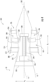
- FIGS. 5 through 7 an electric machine 350 according to an exemplary embodiment of the present subject matter will be described. More specifically, FIG. 5 will provide a cross-sectional view of electric machine 350, FIG. 6 will provide a partial perspective view of a rotor assembly of electric machine 350, and FIG. 7 will provide a stator assembly according to an alternative exemplary embodiment of the present subject matter. Notably, the same or similar numbering may refer to the same or similar parts in FIGS. 5 through 7 .
- electric machine 350 may be used as a motor or generator for any suitable application or in any other suitable device.
- electric machine 350 may be used as a primary or secondary power plant in a land-based vehicle (such as an automobile), in an under-wing mounted propulsion device for an aircraft, for nautical vehicles, etc.
- electric machine 350 includes a rotor assembly 352 and a stator assembly 354, each of which will be described in detail below.
- Electric machine 350 defines an axial direction A3, a radial direction R3, and a circumferential direction C3 (a direction extending about the axial direction A3).
- electric machine 350 may be configured as electric motor 336 for driving BLI fan 300 (see FIG. 4 ).
- electric machine 350 may be configured as electric machine 246, e.g., acting as a generator mechanically coupled to fan 226 (see FIG. 3 ).
- electric machine 350 includes a drive shaft 358 defining a longitudinal axis 362 of electric machine 350.
- longitudinal axis 362 may align with the centerline axis 302 of the BLI fan 300.
- Rotor assembly 352 may optionally include a plurality of bearings (not shown) on axial ends of drive shaft 358.
- rotor assembly 352 includes a rotor disk 364 that is mounted to and extends from drive shaft 358 substantially along the radial direction R3.
- rotor disk 364 is rotatable about the axial direction A3.
- drive shaft 358 and rotor disk 364 may be keyed so as to be in cooperative engagement.
- drive shaft 358 may include one or more features, such as protrusions (not shown), in cooperative engagement with one or more features, such as recesses (not shown), in rotor disk 364, or vice versa.
- drive shaft 358 may include additional features configured to provide passages for a cooling fluid (not shown) within rotor assembly 352.
- the cooling fluid may be airflow or a coolant for reducing mechanical stresses and eddy current losses in the rotor assembly 352.
- rotor assembly 352 includes a plurality of rotor magnets 380.
- stator assembly 354 includes a plurality of stator conductors 382.
- Rotor magnets 380 are configured to generate a rotor magnetic field and stator conductors 382 are configured to generate a stator magnetic field.
- the rotor magnetic field and the stator magnetic field interact to generate a torque that rotates rotor disk 364 and drive shaft 358.
- Rotor magnets 380 may define a magnetization direction (i.e., a north-south pole orientation) that extends along the axial direction A3, e.g., when operating as an "axial flux" machine.
- rotor magnets 380 are configured having a magnetization or pole direction that is oriented substantially axially within the electric machine 350.
- stator assembly 354 is located adjacent rotor magnets 380 along the axial direction A3.
- rotor magnets 380 generate a magnetic field to be axially directed between rotor assembly 352 and stator assembly 354 across an air gap 384 (as illustrated by arrows 386 in FIG. 5 ).
- the magnetic field generated by rotor magnets 380 further interacts with a stator magnetic field produced by its armature currents to produce a torque.
- electric machine 350 may be configured as a "radial flux" machine.
- rotor magnets 380 may be configured to generate a magnetic field that extends substantially along the radial direction R3 between rotor assembly 352 and stator assembly 354 across air gap 384.
- rotor magnets 380 may be arranged in any suitable polarity arrangement.
- the magnetization direction of each rotor magnet extends along the axial direction A3.
- any other suitable magnetization direction or combination or magnetization directions may be used according to alternative embodiments.
- rotor magnets 380 and stator conductors 382 are referred to generally herein as "magnets," it should be appreciated that these magnets may be any suitable magnetic material, and may be permanent magnets, electromagnets, etc.
- rotor magnets 380 are permanent magnets and stator conductors 382 are ferromagnetic material with conductive windings
- rotor magnets 380 are samarium-cobalt magnets or a neodymium magnets.
- alternative embodiments may use any suitable combination of rotor magnets 380 and stator conductors 382 to generate a torque on rotor disk 364 and drive shaft 358.
- stator assembly 354 is illustrated as having concentrated windings, it should be appreciated that stator assembly 354 may alternatively have distributed windings or any other suitable stator winding configuration.
- rotor magnets 380 and stator conductors 382 may include any suitable coating or covering, such as a metallic or non-metallic magnetic shielding material or retaining structure.
- rotor magnets 380 are embedded within rotor disk 364.
- the term "embedded” may refer to a configuration where a rotor magnet 380 is partially or wholly incorporated within the profile or the external boundary of rotor disk 364.
- rotor magnets 380 may be entirely sealed within rotor disk 364.
- the entirety of each rotor magnet 380 is positioned entirely within the external boundary of rotor disk 364.
- rotor magnets 380 may be partially embedded within rotor disk 364.
- rotor disk 364 may define a recess 388 within which at least of a part of rotor magnets 380 are positioned.
- rotor disk 364 may define an aperture that extends through rotor disk 364 along the axial direction A3. The aperture in rotor disk 364 may be configured to receive rotor magnet 380.
- rotor magnet 380 and rotor disk 364 have the same width along the axial direction, such that rotor magnet 380, when embedded within rotor disk 364, sits flush with the surface of rotor disk 364.
- FIG. 6 a partial perspective view of a segment of rotor disk 364 with an embedded rotor magnet 380 is illustrated.
- rotor disk 364 may include a plurality of segments, each segment being configured for receiving one rotor magnet 380.
- rotor disk 364 may be integrally formed as a single unitary part including any suitable number of segments.
- rotor magnet 380 has a trapezoidal shape and is positioned proximate a rotor tip 389.
- rotor magnet 380 may be positioned at any suitable location within rotor disk 364, and may be any suitable size and shape.
- Rotor disk 364 with embedded rotor magnets 380 may be constructed using any suitably rigid material and in any suitable manner. More specifically, rotor disk 364 may be constructed of a material sufficient for withstanding the large centrifugal forces generated during high speed operation (e.g., tip speeds of 1000 feet per second or higher) of electric machine 350. Rotor disk 364 may be constructed in two symmetrical pieces, i.e., as if rotor disk 364 was split in half along a plane perpendicular to the axial direction A3. In this manner, rotor magnet 380 may be placed in one half of rotor disk and the other half may be placed over rotor magnet 380 and joined with the first half to form rotor disk 364. The two halves of rotor disk 364 may be joined using any suitable method, e.g., welding, gluing, mechanical fasteners, etc.
- any suitable method e.g., welding, gluing, mechanical fasteners, etc.
- rotor disk 364 may be manufactured to its desired finished shape and one or more recesses may be machined within rotor disk 364 for receipt of rotor magnets 380.
- Rotor magnets 380 may be secured within the recesses using any suitable method, such as mechanical fasteners, glue, snap-fit mechanisms, press-fit mechanisms, etc.
- a cap piece may be positioned over rotor magnets 380 and may be joined to rotor disk 364, e.g., forming a flush surface with rotor disk 364 and sealing rotor magnets 380 within rotor disk 364.
- rotor disk assembly 352 is designed to absorb centrifugal loads exerted on rotor magnets 380 at high speeds of operation.
- rotor assembly 352 and thus electric machine 350 are designed to withstand high speeds and centrifugal loading.
- rotor disk 364 is formed of a laminated magnetic metal to optimize the magnetic reluctance path and reduce eddy currents.
- Rotor disk 364 may be any size suitable for supporting high speed operation of electric machine 350, e.g., by absorbing centrifugal forces of motor components such as radial stresses and hoop stresses. However, by embedding rotor magnets 380 within rotor disk 364, the overall thickness of rotor disk 364 may be decreased. For example, according to an exemplary embodiment, rotor disk 364 defines a width W measured along the axial direction A3. Using embedded rotor magnets 380, the width W of rotor disk 364 proximate rotor magnet 380 may be less than 5.08cm (two inches). For example, according to the illustrated embodiment, the width W of rotor disk 364 proximate the embedded rotor magnet 380 is less than 2.54cm (one inch).
- a thin rotor disk 364 may enable higher tip speeds and higher specific power of electric machine 350.
- electric machine 350 may define a total length L of both the rotor assembly 352 and stator assembly 354 measured along the axial direction A3.
- Rotor disk 364 may also define a diameter D measured along the radial direction R3.
- electric machine 350 may define a length to diameter (L/D) aspect ratio less than about 1.0.
- the aspect ratio may be less than about 0.5, such as less than about 0.25 or smaller.
- Stator assembly 354 generally includes stator conductors 382, which according to the illustrated embodiment, include a magnetic core 390 that is positioned in magnetic flux communication with rotor magnets 380. More specifically, magnetic core 390 may be placed axially adjacent rotor magnets 380 in an axial flux machine (i.e., FIGS. 5 through 9 ) and radially adjacent rotor magnets 380 in a radial flux machine (not illustrated). Magnetic core 390 may be a magnetically permeable material, e.g., metal, and may include multiple stator-slots (not shown) for receiving conductive armature windings 392. Notably, however, windings 392 are depicted as being integrated into magnetic core 390 for clarity in FIGS. 5 through 9 .
- the armature windings 392 may include copper windings in a variety of topologies and forms.
- stator conductors 382 may be configured as an electromagnet.
- stator conductors 382 are configured to carry a magnetic flux optimally to and from rotor magnets 380.
- magnetic core 390 may be laminated directionally to reduce eddy current heating in the magnetic core 390 and thereby to improve motor efficiency.
- magnetic core 390 may be a solid annular block of continuous magnetic material.
- no stator-slots are needed and conductive armature windings 392 may be mounted directly to a surface of the magnetic core 390 using any suitable method, e.g., gluing.
- the magnetic core 390 and armature windings 392 could then be laminated to reduce eddy current heating in magnetic core 390 and thereby improve the efficiency of electric machine 350.
- the portion of rotor assembly 352 depicted in FIG. 5 may simply be one module of the rotor assembly 352.
- a plurality of modules may be included to provide a desired power output for the electric machine 350, with the more rotor modules included, the higher the power output.
- Electric machine 350 includes a rotor-stator-rotor configuration.
- a single stator assembly 354 is positioned between two rotor assemblies 352.
- rotor magnet 380 may include a rotor back iron 394 for turning around the magnetic flux (as illustrated by arrows 386 in FIG. 8 ).
- a plurality of rotor assemblies 352 and a plurality of stator assemblies 354 may be alternately stacked to increase the power output of electric machine 350.
- three rotor assemblies 352 are positioned between four stator assemblies 354 along the axial direction A3.
- magnetic flux (identified by arrow 386) may be passed from a first stator assembly 354 on one end of electric machine 350 through the rotor assemblies 352 and stator assemblies 354 along the axial direction A3.
- the final stator assembly 354 may turn the magnetic flux around and return it to the first stator assembly 354.
- electric machine 350 includes a rotor assembly 352 capable of operating at relatively high speeds, despite the high centrifugal forces and stresses exerted on rotor assembly 352 and other components of electric machine 350.
- electric machine 350 may operate at high speeds as determined by the electric machine average airgap speed (described below).
- electric machine 350 defines an electric machine average airgap speed during operation of electric machine 350.
- the electric machine average airgap speed refers to a general measure of the speed of the rotor disk 364 at airgap 384 (e.g., a surface speed or linear speed of rotor disk 364). As will be appreciated, such an average airgap speed may be calculated by multiplying a rotational speed of rotor disk 364 of electric machine 350 by an average radial centerline of airgap 384. For example, on an axial flux machine, the average radial centerline is the average radius of stator conductor 382 along the radial direction R3. For a radial flux machine, the average radial centerline is the radial center of airgap 384 along the radial direction R3.
- electric machine 350 may be configured to operate at electric machine tip speeds above about 750 feet per second (ft/s). More particularly, an electric machine in accordance with one or more exemplary embodiments of the present disclosure may operate during standard day, maximum speed conditions with an electric machine tip speed above about 850 feet per second (ft/s), such as above about 900 ft/s, such as above about 1,000 ft/s.
- rotor assembly 352 may have a reduced overall size and may be configured for improving the utilization of magnetic flux within electric machine 350.
- Such a configuration allows for increased power density and improved electrical performance. Therefore, an electric machine in accordance with one or more embodiments of the present disclosure may provide for an electric machine having a desired efficiency and power density.
- the present disclosure provides additional advantages in terms of low volume, mass, and cost. These techniques and systems thus allow for an electric machine having a higher power-to-weight ratio that is more robust than prior designs. More particularly, the provided electric machine 350 as disclosed herein is capable of running at higher speeds and loads, effectively permitting a smaller machine to handle higher loads.
- Rotor assembly 400 may be used with any suitable stator assembly and in any suitable electric machine.
- Rotor assembly 400 may be used with electric machine 350 and may interact with stator assembly 354 as a motor for generating torque from electrical energy or as a generator for generating electrical energy from torque.
- rotor assembly 400 includes a rotor disk 402 that is mounted to and extends from a drive shaft (not shown) substantially along the radial direction R3.
- Rotor assembly 400 may further include a plurality of rotor magnets 404, which are configured to interact with stator magnets and a stator assembly to produce torque in a manner similar to that described above.
- Rotor magnets 404 may define a magnetization direction (i.e., a north-south pole orientation) that extends along the axial direction A3. As a result, the stator assembly is located adjacent rotor magnets 404 along the axial direction A3. In this regard, rotor magnets 404 generate a magnetic field to be axially directed between rotor assembly 400 and the stator assembly across an air gap. Furthermore, rotor magnets 404 may include any suitable coating or covering, such as a metallic or non-metallic magnetic shielding material or retaining structure.
- rotor magnets 404 are embedded within rotor disk 402.
- rotor magnets 404 and the construction of rotor disk 402 may be similar to the embodiment described above with respect to FIGS. 5 through 9 .
- rotor disk 402 may define one or more recesses 406 within which at least a part of rotor magnets 404 are positioned.
- recesses 406 and rotor magnets 404 have a trapezoidal shape and are positioned proximate a rotor tip 408.
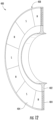
- rotor magnets 404 are spaced apart along the circumferential direction C3, such that a hub and spoke arrangement is formed for supporting centrifugal loads. More specifically, rotor magnets 406 may be spaced apart to define radially extending spokes 410 that provide additional centrifugal stiffening of rotor disk 402.
- rotor magnets 404 may be positioned at any suitable location within rotor disk 402, and may be any suitable size and shape. According to the invention, referring briefly to FIG. 12 , rotor magnets 404 are formed as a continuous magnet embedded within rotor disk 402 and extending along the circumferential direction C3. In this regard, the rotor magnets 404 have alternating polarity portions arranged along the circumferential direction C3.
- rotor disk 402 with embedded rotor magnets 404 may be constructed using any suitably rigid material and in any suitable manner.
- rotor assembly 400 includes two rotor magnets 404 separated by a web 412.
- Web 412 may be constructed in any suitable manner and may be made of any suitable material.
- web 412 is the same material as rotor disk 402.
- recesses 406 may be defined by machining out material from rotor disk 402, leaving web 412 to be positioned between rotor magnets 404.
- Rotor magnets 404 may be secured within recesses 406 using any suitable method, such as mechanical fasteners, glue, snap-fit mechanisms, press-fit mechanisms, etc.
- web 412 may be a different material than rotor disk 402.
- rotor disk 402 may be a two-part disk that sandwiches web 412.
- Rotor disk 402 may be constructed in two symmetric or asymmetric pieces, i.e., as if rotor disk 402 was split in half along a plane perpendicular to the axial direction A3.
- the two halves of rotor disk 402 may be joined using any suitable method, e.g., welding, gluing, mechanical fasteners, etc.
- web 412 may be ferromagnetic or non-magnetic.
- rotor magnets 404 may be entirely sealed within rotor disk 402, such that rotor magnets 404 have no exposed surfaces outside rotor disk 402.
- rotor disk 402 may define an additional retaining structure positioned on one or both axial ends of rotor disk 402.
- the retaining structure may be positioned over rotor magnets 404 and may be joined to rotor disk 402, e.g., forming a flush surface with rotor disk 402 and sealing rotor magnets 404 within rotor disk 402.
- one or more coatings may be applied to the surface of rotor disk 402 and over rotor magnets 404, e.g., to assist in the transfer of magnetic flux, to reduce corrosion, to provide axial retention force to rotor magnets 404, or for any other suitable purpose.
- rotor magnets may be only partially embedded, such that some surface of rotor magnets 404 are exposed outside rotor disk 402.
- rotor disk assembly 400 is designed to absorb centrifugal loads exerted on rotor magnets 404 at high speeds of operation. As such, rotor assembly 400 and thus electric machine 350 are designed to withstand high speeds and centrifugal loading.
- electric machine 350 may alternatively be configured in any other suitable manner.
- electric machine 350 may be configured in accordance with one or more of the exemplary configurations described in United States Patent Application Serial Number 14/317,294 (published at the time of filing as United States Patent Publication Number 2015/0380999 ).
- electric machine 350 illustrated herein is configured as an "outrunner” motor, it should be appreciated that electric machine 350 could also be configured as an "inrunner” electric machine while remaining within the scope of the present subject matter.
Landscapes
- Engineering & Computer Science (AREA)
- Power Engineering (AREA)
- Aviation & Aerospace Engineering (AREA)
- Permanent Magnet Type Synchronous Machine (AREA)
Description
- The present subject matter relates generally to an electric machine, and more particularly, to a high speed electric machine.
- Electric machines, e.g., electric motors and generators, are used in a variety of industries to convert electrical energy to mechanical energy, and vice versa, for useful purposes. For example electric machines are used in the automotive, aviation, maritime, and other industries to operate aircrafts, helicopters, automobiles, boats, submarines, trains, and/or any other suitable vehicles.
- To reduce fuel consumption and improve propulsive efficiency, it is generally desirable to use electric machines with large power densities, referred to herein as the electric machine's specific power or power-to-weight ratio. Electric machines having a high specific power may be smaller and more lightweight while generating equivalent or greater power than heavier electric machines.
- Increasing the rotation speeds of electric machines is known to increase power-to-weight ratios. However, as the rotational speeds increase, the stresses on the various rotating components of the electric machine also increase. As a result the retaining structure for holding the rotating components of the electric machine must be larger and heavier, thus increasing costs, size, and weight. For example, certain electric machines use a disk retaining structure which allows for much higher tip speeds and power densities than conventional machines. However, as the rotor disk experiences large centrifugal forces during high speed operation, the stresses exerted on rotor disk by the rotor components may limit the ability of the electric machine to reach higher speeds.
- In addition, conventional disk architectures for electric machines utilize two rotor magnets positioned on either side of a rotor disk. A stator assembly is positioned adjacent each rotor magnet such that the magnetic flux passes from one stator assembly, through both rotor magnets and the rotor disk, to the other stator assembly. Such a construction necessitates thicker magnets to maintain the flux and a larger rotor disk to support the magnets. Alternatively, rotor back irons may be used on each side of the rotor disk to return the magnetic flux to each respective stator assembly. Both constructions result in additional costs, size, and weight.
- Accordingly, an electric machine with features for improving specific power and efficiency is desirable. More specifically, an electric machine with features for enabling improved utilization of magnetic flux and high speed operation of the electric machine to improve performance and specific power would be particularly beneficial.
-
US 2016/0329795 describes an axial flux brushless electrical machine having a stator and at least one rotor. - Aspects and advantages of the invention will be set forth in part in the following description, or may be obvious from the description, or may be learned through practice of the invention.
- In an example of the present disclosure not corresponding to the invention which is defined by the appended claims, an electric machine defining an axial direction, a radial direction, and a circumferential direction is provided. The electric machine includes a stator assembly and a rotor disk rotatable about the axial direction relative to the stator assembly. The rotor disk includes a rotor magnet embedded therein and operable with the stator assembly to produce a torque, the rotor magnet of the rotor disk spaced from the stator assembly along the axial direction of the electric machine to generate an axial flux across an airgap. The rotor magnets are a continuous magnet embedded within the rotor disk and extending along the circumferential direction, wherein the continuous magnet comprises alternating polarity portions arranged along the circumferential direction.
- The electric machine may be configured for driving an aeronautical propulsion device for an aircraft. The electric machine includes a drive shaft mechanically coupled to a boundary layer ingestion fan, the rotor disk mounted to the drive shaft.
- These and other features, aspects and advantages of the present invention will become better understood with reference to the following description and appended claims. The accompanying drawings, which are incorporated in and constitute a part of this specification, illustrate embodiments of the invention and, together with the description, serve to explain the principles of the invention.
- A full and enabling disclosure of the present invention, including the best mode thereof, directed to one of ordinary skill in the art, is set forth in the specification, which makes reference to the appended figures, in which:
-
FIG. 1 is a top view of an aircraft according to various exemplary embodiments of the present disclosure. -
FIG. 2 is a port side view of the exemplary aircraft ofFIG. 1 -
FIG. 3 is a schematic, cross-sectional view of a gas turbine engine mounted to the exemplary aircraft ofFIG. 1 . -
FIG. 4 is a schematic, cross-sectional view of an aft engine in accordance with an exemplary embodiment of the present disclosure. -
FIG. 5 is a cross-sectional view of an electric machine for the exemplary aft engine ofFIG. 4 in accordance with an exemplary embodiment of the present disclosure. -
FIG. 6 is a partial perspective view of a rotor assembly of the exemplary electric machine ofFIG. 5 in accordance with an example not corresponding to the invention. -
FIG. 7 is a cross-sectional view of another electric machine for the exemplary aft engine ofFIG. 4 in accordance with an exemplary embodiment of the present disclosure. -
FIG. 8 is a cross-sectional view of another electric machine for the exemplary aft engine ofFIG. 4 , including two rotor assemblies in accordance with an exemplary embodiment of the present disclosure. -
FIG. 9 is a cross-sectional view of another electric machine for the exemplary aft engine ofFIG. 4 , including a plurality of alternately stacked rotor and stator assemblies in accordance with an exemplary embodiment of the present disclosure. -
FIG. 10 is a perspective, cross-sectional view of a rotor disk of another electric machine for the exemplary aft engine ofFIG. 4 according to an example which does not correspond to the invention. -
FIG. 11 is a cross-sectional view of the rotor disk of the exemplary electric machine ofFIG. 10 according to an exemplary embodiment of the present subject matter. -
FIG. 12 is a perspective, cross-sectional view of a rotor disk having a continuous embedded magnet according to an exemplary embodiment of the present subject matter. - Reference will now be made in detail to present embodiments of the invention, one or more examples of which are illustrated in the accompanying drawings. The detailed description uses numerical and letter designations to refer to features in the drawings. Like or similar designations in the drawings and description have been used to refer to like or similar parts of the invention.
- As used herein, the terms "first", "second", and "third" may be used interchangeably to distinguish one component from another and are not intended to signify location or importance of the individual components. The terms "forward" and "aft" refer to the relative positions of a component based on an actual or anticipated direction of travel. For example, "forward" may refer to a front of an aircraft based on an anticipated direction of travel of the aircraft, and "aft" may refer to a back of the aircraft based on an anticipated direction of travel of the aircraft. The terms "upstream" and "downstream" refer to the relative direction with respect to fluid flow in a fluid pathway. For example, "upstream" refers to the direction from which the fluid flows, and "downstream" refers to the direction to which the fluid flows.
- Referring now to the drawings, wherein identical numerals indicate the same elements throughout the figures,
FIG. 1 provides a top view of anexemplary aircraft 10 as may incorporate various embodiments of the present invention.FIG. 2 provides a port side view of theaircraft 10 as illustrated inFIG. 1 . As shown inFIGS. 1 and 2 collectively, theaircraft 10 defines alongitudinal centerline 14 that extends therethrough, a vertical direction V, a lateral direction L, aforward end 16, and anaft end 18. Moreover, theaircraft 10 defines amean line 15 extending between theforward end 16 andaft end 18 of theaircraft 10. As used herein, the "mean line" refers to a midpoint line extending along a length of theaircraft 10, not taking into account the appendages of the aircraft 10 (such as thewings 20 and stabilizers discussed below). - Moreover, the
aircraft 10 includes afuselage 12, extending longitudinally from theforward end 16 of theaircraft 10 towards theaft end 18 of theaircraft 10, and a pair ofwings 20. As used herein, the term "fuselage" generally includes all of the body of theaircraft 10, such as an empennage of theaircraft 10. The first ofsuch wings 20 extends laterally outwardly with respect to thelongitudinal centerline 14 from aport side 22 of thefuselage 12 and the second ofsuch wings 20 extends laterally outwardly with respect to thelongitudinal centerline 14 from astarboard side 24 of thefuselage 12. Each of thewings 20 for the exemplary embodiment depicted includes one or more leadingedge flaps 26 and one or moretrailing edge flaps 28. Theaircraft 10 further includes avertical stabilizer 30 having arudder flap 32 for yaw control, and a pair ofhorizontal stabilizers 34, each having anelevator flap 36 for pitch control. Thefuselage 12 additionally includes an outer surface orskin 38. It should be appreciated however, that in other exemplary embodiments of the present disclosure, theaircraft 10 may additionally or alternatively include any other suitable configuration of stabilizer that may or may not extend directly along the vertical direction V or horizontal/ lateral direction L. - The
exemplary aircraft 10 ofFIGS. 1 and 2 includes apropulsion system 100, herein referred to as "system 100". Theexemplary system 100 includes one or more aircraft engines and one or more electric propulsion engines. For example, the embodiment depicted includes a plurality of aircraft engines, each configured to be mounted to theaircraft 10, such as to one of the pair ofwings 20, and an electric propulsion engine. More specifically, for the embodiment depicted, the aircraft engines are configured as gas turbine engines, or rather asturbofan jet engines wings 20 in an under-wing configuration. Additionally, the electric propulsion engine is configured to be mounted at the aft end of theaircraft 10, and hence the electric propulsion engine depicted may be referred to as an "aft engine." Further, the electric propulsion engine depicted is configured to ingest and consume air forming a boundary layer over thefuselage 12 of theaircraft 10. Accordingly, the exemplary aft engine depicted may be referred to as a boundary layer ingestion (BLI)fan 106. TheBLI fan 106 is mounted to theaircraft 10 at a location aft of thewings 20 and/or thejet engines BLI fan 106 is fixedly connected to thefuselage 12 at theaft end 18, such that theBLI fan 106 is incorporated into or blended with a tail section at theaft end 18, and such that themean line 15 extends therethrough. It should be appreciated, however, that in other embodiments the electric propulsion engine may be configured in any other suitable manner, and may not necessarily be configured as an aft fan or as a BLI fan. - Referring still to the embodiment of
FIGS. 1 and 2 , in certain embodiments the propulsion system further includes one or moreelectric generators 108 operable with thejet engines jet engines electric generators 108. Although depicted schematically outside therespective jet engines electric generators 108 may be positioned within arespective jet engine electric generators 108 may be configured to convert the mechanical power to electrical power. For the embodiment depicted, thepropulsion system 100 includes anelectric generator 108 for eachjet engine power conditioner 109 and anenergy storage device 110. Theelectric generators 108 may send electrical power to thepower conditioner 109, which may transform the electrical energy to a proper form and either store the energy in theenergy storage device 110 or send the electrical energy to theBLI fan 106. For the embodiment depicted, theelectric generators 108,power conditioner 109,energy storage device 110, andBLI fan 106 are all are connected to anelectric communication bus 111, such that theelectric generator 108 may be in electrical communication with theBLI fan 106 and/or theenergy storage device 110, and such that theelectric generator 108 may provide electrical power to one or both of theenergy storage device 110 or theBLI fan 106. Accordingly, in such an embodiment, thepropulsion system 100 may be referred to as a gas-electric propulsion system. - It should be appreciated, however, that the
aircraft 10 andpropulsion system 100 depicted inFIGS. 1 and 2 is provided by way of example only and that in other exemplary embodiments of the present disclosure, any othersuitable aircraft 10 may be provided having apropulsion system 100 configured in any other suitable manner. For example, it should be appreciated that in various other embodiments, theBLI fan 106 may alternatively be positioned at any suitable location proximate theaft end 18 of theaircraft 10. Further, in still other embodiments the electric propulsion engine may not be positioned at the aft end of theaircraft 10, and thus may not be configured as an "aft engine." For example, in other embodiments, the electric propulsion engine may be incorporated into the fuselage of theaircraft 10, and thus configured as a "podded engine," or pod-installation engine. Further, in still other embodiments, the electric propulsion engine may be incorporated into a wing of theaircraft 10, and thus may be configured as a "blended wing engine." Moreover, in other embodiments, the electric propulsion engine may not be a boundary layer ingestion fan, and instead may be mounted at any suitable location on theaircraft 10 as a freestream injection fan. Furthermore, in still other embodiments, thepropulsion system 100 may not include, e.g., thepower conditioner 109 and/or theenergy storage device 110, and instead the generator(s) 108 may be directly connected to theBLI fan 106. - Referring now to
FIG. 3 , a schematic cross-sectional view of a propulsion engine in accordance with an exemplary embodiment of the present disclosure is provided. In certain exemplary embodiments, the propulsion engine may be configured a high-bypass turbofan jet engine 200, herein referred to as "turbofan 200." Notably, in at least certain embodiments, thejet engines jet engines suitable aircraft 10 orpropulsion system 100. - As shown in
FIG. 3 , the turbofan 200 defines an axial direction A1 (extending parallel to a longitudinal centerline 201 provided for reference) and a radial direction R1. In general, the turbofan 200 includes a fan section 202 and a core turbine engine 204 disposed downstream from the fan section 202. - The exemplary core turbine engine 204 depicted generally includes a substantially tubular outer casing 206 that defines an annular inlet 208. The outer casing 206 encases, in serial flow relationship, a compressor section including a booster or low pressure (LP) compressor 210 and a high pressure (HP) compressor 212; a combustion section 214; a turbine section including a high pressure (HP) turbine 216 and a low pressure (LP) turbine 218; and a jet exhaust nozzle section 220. A high pressure (HP) shaft or spool 222 drivingly connects the HP turbine 216 to the HP compressor 212. A low pressure (LP) shaft or spool 224 drivingly connects the LP turbine 218 to the LP compressor 210.
- For the embodiment depicted, the fan section 202 includes a variable pitch fan 226 having a plurality of fan blades 228 coupled to a disk 230 in a spaced apart manner. As depicted, the fan blades 228 extend outwardly from disk 230 generally along the radial direction R1. Each fan blade 228 is rotatable relative to the disk 230 about a pitch axis P by virtue of the fan blades 228 being operatively coupled to a suitable actuation member 232 configured to collectively vary the pitch of the fan blades 228 in unison. The fan blades 228, disk 230, and actuation member 232 are together rotatable about the
longitudinal axis 12 by LP shaft 224 across a power gear box 234. The power gear box 234 includes a plurality of gears for stepping down the rotational speed of the LP shaft 224 to a more efficient rotational fan speed. - Referring still to the exemplary embodiment of
FIG. 3 , the disk 230 is covered by rotatable front hub 236 aerodynamically contoured to promote an airflow through the plurality of fan blades 228. Additionally, the exemplary fan section 202 includes an annular fan casing or outer nacelle 238 that circumferentially surrounds the fan 226 and/or at least a portion of the core turbine engine 204. It should be appreciated that the nacelle 238 may be configured to be supported relative to the core turbine engine 204 by a plurality of circumferentially-spaced outlet guide vanes 240. Moreover, a downstream section 242 of the nacelle 238 may extend over an outer portion of the core turbine engine 204 so as to define a bypass airflow passage 244 therebetween. - Additionally, the exemplary turbofan 200 depicted includes an electric machine 246 rotatable with the fan 226. Specifically, for the embodiment depicted, the electric machine 246 is configured as an electric generator co-axially mounted to and rotatable by the LP shaft 224 (the LP shaft 224 also rotating the fan 226 through, for the embodiment depicted, the power gearbox 234). The electric machine 246 includes a rotor 248 and a stator 250. In certain exemplary embodiments, the rotor 248 and stator 250 of the electric machine 246 are configured in substantially the same manner as the exemplary rotor and stator of the
electric motor 336 described below with reference toFIG. 4 or theelectric machine 350 described below with reference toFIGS. 5 through 9 . Additionally, as will be appreciated, the rotor 248 may be attached to the LP shaft 224 and the stator 250 may remain static within the core turbine engine 204. During operation, the electric machine may define an electric machine tip speed (i.e., a linear speed of the rotor 248 at an airgap radius of electric machine 246, as described below). Notably, when the turbofan engine 200 is integrated into thepropulsion system 100 described above with reference toFIGS. 1 and 2 , theelectric generators 108 may be configured in substantially the same manner as the electric machine 246 ofFIG. 3 . - It should also be appreciated, however, that the exemplary turbofan engine 200 depicted in
FIG. 3 is by way of example only, and that in other exemplary embodiments, the turbofan engine 200 may have any other suitable configuration. For example, although rotor 248 is illustrated as being attached to the LP shaft 224, it should be appreciated that rotor 248 could alternatively be attached to the HP shaft 222 or any other suitable shaft. Further, it should be appreciated, that in other exemplary embodiments, thejet engines - Referring now to
FIG. 4 , a schematic, cross-sectional side view of an electric propulsion engine in accordance with various embodiments of the present disclosure is provided. The electric propulsion engine depicted is mounted to anaircraft 10 at anaft end 18 of theaircraft 10 and is configured to ingest a boundary layer air. Accordingly, for the embodiment depicted, the electric propulsion engine is configured as a boundary layer ingestion (BLI), aft fan (referred to hereinafter as "BLI fan 300"). TheBLI fan 300 may be configured in substantially the same manner as theBLI fan 106 described above with reference toFIGS. 1 and 2 and theaircraft 10 may be configured in substantially the same manner as theexemplary aircraft 10 described above with reference toFIGS. 1 and 2 . - As shown in
FIG. 4 , theBLI fan 300 defines an axial direction A2 extending along a longitudinal centerline axis 302 (or center axis) that extends therethrough for reference, as well as a radial direction R2 and a circumferential direction C2 (a direction extending about the axial direction A2, not shown). Additionally, theaircraft 10 defines amean line 15 extending therethrough. - In general, the
BLI fan 300 includes afan 304 rotatable about thecenterline axis 302 and astructural support system 308. Thestructural support system 308 is configured for mounting theBLI fan 300 to theaircraft 10, and for the embodiment depicted generally includes aninner frame support 310, a plurality offorward support members 312, anouter nacelle 314, a plurality ofaft support members 316, and atail cone 318. As is depicted, theinner frame support 310 is attached to abulkhead 320 of thefuselage 12. The plurality offorward support members 312 are attached to theinner frame support 310 and extend outward generally along the radial direction R2 to thenacelle 314. Thenacelle 314 defines anairflow passage 322 with aninner casing 324 of theBLI fan 300, and at least partially surrounds thefan 304. Further, for the embodiment depicted, thenacelle 314 extends substantially three hundred and sixty degrees (360°) around themean line 15 of theaircraft 10. The plurality ofaft support members 316 also extend generally along the radial direction R2 from, and structurally connect, thenacelle 314 to thetail cone 318. - In certain embodiments, the
forward support members 312 and theaft support members 316 may each be generally spaced along the circumferential direction C2 of theBLI fan 300. Additionally, in certain embodiments theforward support members 312 may be generally configured as inlet guide vanes and theaft support members 316 may generally be configured as outlet guide vanes. If configured in such a manner, the forward andaft support members airflow passage 322 of theBLI fan 300. Notably, one or both of theforward support members 312 oraft support members 316 may additionally be configured as variable guide vanes. For example, the support member may include a flap (not shown) positioned at an aft end of the support member for directing a flow of air across the support member. - It should be appreciated, however, that in other exemplary embodiments, the
structural support system 308 may instead include any other suitable configuration and, e.g., may not include each of the components depicted and described above. Alternatively, thestructural support system 308 may include any other suitable components not depicted or described above. - The
BLI fan 300 additionally defines anozzle 326 between thenacelle 314 and thetail cone 318. Thenozzle 326 may be configured to generate an amount of thrust from the air flowing therethrough, and thetail cone 318 may be shaped to minimize an amount of drag on theBLI fan 300. However, in other embodiments, thetail cone 318 may have any other shape and may, e.g., end forward of an aft end of thenacelle 314 such that thetail cone 318 is enclosed by thenacelle 314 at an aft end. Additionally, in other embodiments, theBLI fan 300 may not be configured to generate any measureable amount of thrust, and instead may be configured to ingest air from a boundary layer of air of thefuselage 12 of theaircraft 10 and add energy/ speed up such air to reduce an overall drag on the aircraft 10 (and thus increase a net thrust of the aircraft 10). - Referring still to
FIG. 4 , thefan 304 includes a plurality offan blades 328 and afan shaft 330. The plurality offan blades 328 are attached to thefan shaft 330 and spaced generally along the circumferential direction C2 of theBLI fan 300. As depicted, theplurality fan blades 328 are, for the embodiment depicted, at least partially enclosed by thenacelle 314. - Moreover, for the embodiment depicted, the
fan 304 is rotatable about thecenterline axis 302 of theBLI fan 300 by an electric machine. More particularly, for the embodiment depicted, the electric machine is configured as anelectric motor 336 and theBLI fan 300 additionally includes apower gearbox 338 mechanically coupled to theelectric motor 336. Additionally, thefan 304 is mechanically coupled to thepower gearbox 338. For example, for the embodiment depicted, thefan shaft 330 extends to and is coupled to thepower gearbox 338, and adriveshaft 340 of theelectric motor 336 extends to and is also coupled to thepower gearbox 338. Accordingly, for the embodiment depicted, thefan 304 is rotatable about thecentral axis 302 of theBLI fan 300 by theelectric motor 336 through thepower gearbox 338. - The
power gearbox 338 may include any type of gearing system for altering a rotational speed between thedriveshaft 340 and thefan shaft 330. For example, thepower gearbox 338 may be configured as a star gear train, a planetary gear train, or any other suitable gear train configuration. Additionally, thepower gearbox 338 may define a gear ratio, which as used herein, refers to a ratio of a rotational speed of thedriveshaft 340 to a rotational speed of thefan shaft 330. In certain exemplary embodiments, the gear ratio of thepower gearbox 338 may be greater than about 1:1 and less than about 1:5. For example, in certain embodiments, the gear ratio of thepower gearbox 338 may be between about 1:1.5 and about 1:3.5, such as between about 1:1.2 and about 1:2.75. It should be appreciated, that as used herein, terms of approximation, such as "about" or "approximately," refer to being within a 10% margin of error. - Referring still to the exemplary embodiment of
FIG. 4 , theelectric motor 336 is located at least partially within thefuselage 12 of theaircraft 10. More specifically, thefan 304 is positioned forward of thepower gearbox 338 along thecentral axis 302 of theBLI fan 300, and theelectric motor 336 is positioned forward of thefan 304 along thecentral axis 302 of theBLI fan 300. However, according to alternative embodiments,power gearbox 338 could be positioned at a forward location or at any other suitable location withinaircraft 10. - Further, in certain exemplary embodiments, the
BLI fan 300 may be configured with a gas-electric propulsion system, such as the gas-electric propulsion system 100 described above with reference toFIGS. 1 and 2 . In such an embodiment, theelectric motor 336 may receive power from one or both of an energy storage device or an electric generator-such as theenergy storage device 110 orelectric generator 108 ofFIGS. 1 and 2 . - Referring now to
FIGS. 5 through 7 , anelectric machine 350 according to an exemplary embodiment of the present subject matter will be described. More specifically,FIG. 5 will provide a cross-sectional view ofelectric machine 350,FIG. 6 will provide a partial perspective view of a rotor assembly ofelectric machine 350, andFIG. 7 will provide a stator assembly according to an alternative exemplary embodiment of the present subject matter. Notably, the same or similar numbering may refer to the same or similar parts inFIGS. 5 through 7 . Although described below as being configured for driving a boundary layer ingestion fan for an aircraft, it should be appreciated that in other exemplary embodiments,electric machine 350 may be used as a motor or generator for any suitable application or in any other suitable device. For example,electric machine 350 may be used as a primary or secondary power plant in a land-based vehicle (such as an automobile), in an under-wing mounted propulsion device for an aircraft, for nautical vehicles, etc. - As illustrated,
electric machine 350 includes arotor assembly 352 and astator assembly 354, each of which will be described in detail below.Electric machine 350 defines an axial direction A3, a radial direction R3, and a circumferential direction C3 (a direction extending about the axial direction A3). According to one embodiment,electric machine 350 may be configured aselectric motor 336 for driving BLI fan 300 (seeFIG. 4 ). According to another exemplary embodiment,electric machine 350 may be configured as electric machine 246, e.g., acting as a generator mechanically coupled to fan 226 (seeFIG. 3 ). - As illustrated in
FIG. 5 ,electric machine 350 includes adrive shaft 358 defining alongitudinal axis 362 ofelectric machine 350. According to one exemplary embodiment, whenelectric machine 350 is installed in theBLI fan 300,longitudinal axis 362 may align with thecenterline axis 302 of theBLI fan 300.Rotor assembly 352 may optionally include a plurality of bearings (not shown) on axial ends ofdrive shaft 358. - Referring now generally to
FIGS. 5 through 7 ,rotor assembly 352 includes arotor disk 364 that is mounted to and extends fromdrive shaft 358 substantially along the radial direction R3. In this regard,rotor disk 364 is rotatable about the axial direction A3. In an embodiment,drive shaft 358 androtor disk 364 may be keyed so as to be in cooperative engagement. In an embodiment,drive shaft 358 may include one or more features, such as protrusions (not shown), in cooperative engagement with one or more features, such as recesses (not shown), inrotor disk 364, or vice versa. In an embodiment,drive shaft 358 may include additional features configured to provide passages for a cooling fluid (not shown) withinrotor assembly 352. In a non-limiting example, the cooling fluid may be airflow or a coolant for reducing mechanical stresses and eddy current losses in therotor assembly 352. - Still referring to
FIGS. 5 through 7 , according to the illustrated exemplary embodiment,rotor assembly 352 includes a plurality ofrotor magnets 380. Similarlystator assembly 354 includes a plurality ofstator conductors 382.Rotor magnets 380 are configured to generate a rotor magnetic field andstator conductors 382 are configured to generate a stator magnetic field. In general, the rotor magnetic field and the stator magnetic field interact to generate a torque that rotatesrotor disk 364 and driveshaft 358. -
Rotor magnets 380 may define a magnetization direction (i.e., a north-south pole orientation) that extends along the axial direction A3, e.g., when operating as an "axial flux" machine. For example, in the illustrated exemplary embodiment ofFIGS. 5 through 7 ,rotor magnets 380 are configured having a magnetization or pole direction that is oriented substantially axially within theelectric machine 350. As a result,stator assembly 354 is locatedadjacent rotor magnets 380 along the axial direction A3. In this regard,rotor magnets 380 generate a magnetic field to be axially directed betweenrotor assembly 352 andstator assembly 354 across an air gap 384 (as illustrated byarrows 386 inFIG. 5 ). As described herein, the magnetic field generated byrotor magnets 380 further interacts with a stator magnetic field produced by its armature currents to produce a torque. - It should be appreciated, however, that according to alternative embodiments,
electric machine 350 may be configured as a "radial flux" machine. In a radial flux machine,rotor magnets 380 may be configured to generate a magnetic field that extends substantially along the radial direction R3 betweenrotor assembly 352 andstator assembly 354 acrossair gap 384. According to other exemplary embodiments,rotor magnets 380 may be arranged in any suitable polarity arrangement. For example, according to the illustrated embodiment, the magnetization direction of each rotor magnet extends along the axial direction A3. However, any other suitable magnetization direction or combination or magnetization directions may be used according to alternative embodiments. - Although
rotor magnets 380 andstator conductors 382 are referred to generally herein as "magnets," it should be appreciated that these magnets may be any suitable magnetic material, and may be permanent magnets, electromagnets, etc. For example, according to the illustrated embodiment,rotor magnets 380 are permanent magnets andstator conductors 382 are ferromagnetic material with conductive windings In this regard, for example,rotor magnets 380 are samarium-cobalt magnets or a neodymium magnets. However, it should be appreciated that alternative embodiments may use any suitable combination ofrotor magnets 380 andstator conductors 382 to generate a torque onrotor disk 364 and driveshaft 358. In addition, althoughstator assembly 354 is illustrated as having concentrated windings, it should be appreciated thatstator assembly 354 may alternatively have distributed windings or any other suitable stator winding configuration. Furthermore,rotor magnets 380 andstator conductors 382 may include any suitable coating or covering, such as a metallic or non-metallic magnetic shielding material or retaining structure. - According to the illustrated exemplary embodiment,
rotor magnets 380 are embedded withinrotor disk 364. As used herein, the term "embedded" may refer to a configuration where arotor magnet 380 is partially or wholly incorporated within the profile or the external boundary ofrotor disk 364. For example, according to one exemplary embodiment,rotor magnets 380 may be entirely sealed withinrotor disk 364. In this regard, for example, the entirety of eachrotor magnet 380 is positioned entirely within the external boundary ofrotor disk 364. - However, according to alternative embodiments,
rotor magnets 380 may be partially embedded withinrotor disk 364. For example,rotor disk 364 may define arecess 388 within which at least of a part ofrotor magnets 380 are positioned. According to other exemplary embodiments,rotor disk 364 may define an aperture that extends throughrotor disk 364 along the axial direction A3. The aperture inrotor disk 364 may be configured to receiverotor magnet 380. According to one embodiment,rotor magnet 380 androtor disk 364 have the same width along the axial direction, such thatrotor magnet 380, when embedded withinrotor disk 364, sits flush with the surface ofrotor disk 364. - Referring now to
FIG. 6 , a partial perspective view of a segment ofrotor disk 364 with an embeddedrotor magnet 380 is illustrated. AlthoughFIG. 6 illustrates a single segment, it should be appreciated thatrotor disk 364 may include a plurality of segments, each segment being configured for receiving onerotor magnet 380. Moreover,rotor disk 364 may be integrally formed as a single unitary part including any suitable number of segments. As illustrated,rotor magnet 380 has a trapezoidal shape and is positioned proximate arotor tip 389. According to alternative embodiments,rotor magnet 380 may be positioned at any suitable location withinrotor disk 364, and may be any suitable size and shape. -
Rotor disk 364 with embeddedrotor magnets 380 may be constructed using any suitably rigid material and in any suitable manner. More specifically,rotor disk 364 may be constructed of a material sufficient for withstanding the large centrifugal forces generated during high speed operation (e.g., tip speeds of 1000 feet per second or higher) ofelectric machine 350.Rotor disk 364 may be constructed in two symmetrical pieces, i.e., as ifrotor disk 364 was split in half along a plane perpendicular to the axial direction A3. In this manner,rotor magnet 380 may be placed in one half of rotor disk and the other half may be placed overrotor magnet 380 and joined with the first half to formrotor disk 364. The two halves ofrotor disk 364 may be joined using any suitable method, e.g., welding, gluing, mechanical fasteners, etc. - According to another exemplary embodiment,
rotor disk 364 may be manufactured to its desired finished shape and one or more recesses may be machined withinrotor disk 364 for receipt ofrotor magnets 380.Rotor magnets 380 may be secured within the recesses using any suitable method, such as mechanical fasteners, glue, snap-fit mechanisms, press-fit mechanisms, etc. In addition, or alternatively, a cap piece may be positioned overrotor magnets 380 and may be joined torotor disk 364, e.g., forming a flush surface withrotor disk 364 and sealingrotor magnets 380 withinrotor disk 364. - Notably, by embedding
rotor magnets 380 withinrotor disk 364,rotor disk assembly 352 is designed to absorb centrifugal loads exerted onrotor magnets 380 at high speeds of operation. As such,rotor assembly 352 and thuselectric machine 350 are designed to withstand high speeds and centrifugal loading. In an embodiment,rotor disk 364 is formed of a laminated magnetic metal to optimize the magnetic reluctance path and reduce eddy currents. -
Rotor disk 364 may be any size suitable for supporting high speed operation ofelectric machine 350, e.g., by absorbing centrifugal forces of motor components such as radial stresses and hoop stresses. However, by embeddingrotor magnets 380 withinrotor disk 364, the overall thickness ofrotor disk 364 may be decreased. For example, according to an exemplary embodiment,rotor disk 364 defines a width W measured along the axial direction A3. Using embeddedrotor magnets 380, the width W ofrotor disk 364proximate rotor magnet 380 may be less than 5.08cm (two inches). For example, according to the illustrated embodiment, the width W ofrotor disk 364 proximate the embeddedrotor magnet 380 is less than 2.54cm (one inch). - Notably, a thin rotor disk 364 (i.e., a
rotor disk 364 with a small width W) may enable higher tip speeds and higher specific power ofelectric machine 350. In this regard,electric machine 350 may define a total length L of both therotor assembly 352 andstator assembly 354 measured along the axial direction A3.Rotor disk 364 may also define a diameter D measured along the radial direction R3. In certain exemplary embodiments,electric machine 350 may define a length to diameter (L/D) aspect ratio less than about 1.0. For example, in certain embodiments, the aspect ratio may be less than about 0.5, such as less than about 0.25 or smaller. It should be appreciated, that as used herein, terms of approximation, such as "about" or "approximately," refer to being within a 10% margin. -
Stator assembly 354 generally includesstator conductors 382, which according to the illustrated embodiment, include amagnetic core 390 that is positioned in magnetic flux communication withrotor magnets 380. More specifically,magnetic core 390 may be placed axiallyadjacent rotor magnets 380 in an axial flux machine (i.e.,FIGS. 5 through 9 ) and radiallyadjacent rotor magnets 380 in a radial flux machine (not illustrated).Magnetic core 390 may be a magnetically permeable material, e.g., metal, and may include multiple stator-slots (not shown) for receivingconductive armature windings 392. Notably, however,windings 392 are depicted as being integrated intomagnetic core 390 for clarity inFIGS. 5 through 9 . Thearmature windings 392 may include copper windings in a variety of topologies and forms. As such,stator conductors 382 may be configured as an electromagnet. In an embodiment,stator conductors 382 are configured to carry a magnetic flux optimally to and fromrotor magnets 380. In addition,magnetic core 390 may be laminated directionally to reduce eddy current heating in themagnetic core 390 and thereby to improve motor efficiency. - Referring now to
FIG. 7 , according to an alternative embodiment,magnetic core 390 may be a solid annular block of continuous magnetic material. In such an embodiment, no stator-slots are needed andconductive armature windings 392 may be mounted directly to a surface of themagnetic core 390 using any suitable method, e.g., gluing. Themagnetic core 390 andarmature windings 392 could then be laminated to reduce eddy current heating inmagnetic core 390 and thereby improve the efficiency ofelectric machine 350. - Notably, the portion of
rotor assembly 352 depicted inFIG. 5 may simply be one module of therotor assembly 352. In other embodiments, a plurality of modules may be included to provide a desired power output for theelectric machine 350, with the more rotor modules included, the higher the power output. - For example, referring now to
FIG. 8 , a cross sectional viewelectric machine 350 in accordance with another exemplary embodiment of the present disclosure is depicted. The exemplary rotor assembly and stator assembly may be configured in substantially the same manner aselectric machine 350 depicted inFIGS. 5 through 7 and described above. Accordingly, the same or similar numbering may refer to the same or similar parts.Electric machine 350, as illustrated inFIG. 8 , includes a rotor-stator-rotor configuration. In this regard, asingle stator assembly 354 is positioned between tworotor assemblies 352. Notably,rotor magnet 380 may include a rotor backiron 394 for turning around the magnetic flux (as illustrated byarrows 386 inFIG. 8 ). - Referring now to the exemplary embodiment of
FIG. 9 , a plurality ofrotor assemblies 352 and a plurality ofstator assemblies 354 may be alternately stacked to increase the power output ofelectric machine 350. According to the illustrated embodiment, threerotor assemblies 352 are positioned between fourstator assemblies 354 along the axial direction A3. In this manner, magnetic flux (identified by arrow 386) may be passed from afirst stator assembly 354 on one end ofelectric machine 350 through therotor assemblies 352 andstator assemblies 354 along the axial direction A3. Thefinal stator assembly 354 may turn the magnetic flux around and return it to thefirst stator assembly 354. - The
rotor assembly 352,stator assembly 354, and the various associated components described herein are primarily configured to maximize power density and electrical performance of an electric machine. For example,electric machine 350 includes arotor assembly 352 capable of operating at relatively high speeds, despite the high centrifugal forces and stresses exerted onrotor assembly 352 and other components ofelectric machine 350. For example,electric machine 350 may operate at high speeds as determined by the electric machine average airgap speed (described below). For example,electric machine 350 defines an electric machine average airgap speed during operation ofelectric machine 350. The electric machine average airgap speed refers to a general measure of the speed of therotor disk 364 at airgap 384 (e.g., a surface speed or linear speed of rotor disk 364). As will be appreciated, such an average airgap speed may be calculated by multiplying a rotational speed ofrotor disk 364 ofelectric machine 350 by an average radial centerline ofairgap 384. For example, on an axial flux machine, the average radial centerline is the average radius ofstator conductor 382 along the radial direction R3. For a radial flux machine, the average radial centerline is the radial center ofairgap 384 along the radial direction R3. As an example,electric machine 350 may be configured to operate at electric machine tip speeds above about 750 feet per second (ft/s). More particularly, an electric machine in accordance with one or more exemplary embodiments of the present disclosure may operate during standard day, maximum speed conditions with an electric machine tip speed above about 850 feet per second (ft/s), such as above about 900 ft/s, such as above about 1,000 ft/s. - In addition,
rotor assembly 352 may have a reduced overall size and may be configured for improving the utilization of magnetic flux withinelectric machine 350. Such a configuration allows for increased power density and improved electrical performance. Therefore, an electric machine in accordance with one or more embodiments of the present disclosure may provide for an electric machine having a desired efficiency and power density. Furthermore, the present disclosure provides additional advantages in terms of low volume, mass, and cost. These techniques and systems thus allow for an electric machine having a higher power-to-weight ratio that is more robust than prior designs. More particularly, the providedelectric machine 350 as disclosed herein is capable of running at higher speeds and loads, effectively permitting a smaller machine to handle higher loads. - Referring now to
FIGS. 10 and11 , arotor assembly 400 that may be used with an electric machine according to an exemplary embodiment of the present subject matter will be described.Rotor assembly 400 may be used with any suitable stator assembly and in any suitable electric machine. For example,rotor assembly 400 may be used withelectric machine 350 and may interact withstator assembly 354 as a motor for generating torque from electrical energy or as a generator for generating electrical energy from torque. - Similar to the embodiments described above,
rotor assembly 400 includes arotor disk 402 that is mounted to and extends from a drive shaft (not shown) substantially along the radial direction R3.Rotor assembly 400 may further include a plurality ofrotor magnets 404, which are configured to interact with stator magnets and a stator assembly to produce torque in a manner similar to that described above. -
Rotor magnets 404 may define a magnetization direction (i.e., a north-south pole orientation) that extends along the axial direction A3. As a result, the stator assembly is locatedadjacent rotor magnets 404 along the axial direction A3. In this regard,rotor magnets 404 generate a magnetic field to be axially directed betweenrotor assembly 400 and the stator assembly across an air gap. Furthermore,rotor magnets 404 may include any suitable coating or covering, such as a metallic or non-metallic magnetic shielding material or retaining structure. - According to the illustrated exemplary embodiment,
rotor magnets 404 are embedded withinrotor disk 402. In this regard,rotor magnets 404 and the construction ofrotor disk 402 may be similar to the embodiment described above with respect toFIGS. 5 through 9 . For example, as best illustrated inFIG. 11 ,rotor disk 402 may define one ormore recesses 406 within which at least a part ofrotor magnets 404 are positioned. As illustrated, recesses 406 androtor magnets 404 have a trapezoidal shape and are positioned proximate arotor tip 408. In addition,rotor magnets 404 are spaced apart along the circumferential direction C3, such that a hub and spoke arrangement is formed for supporting centrifugal loads. More specifically,rotor magnets 406 may be spaced apart to define radially extendingspokes 410 that provide additional centrifugal stiffening ofrotor disk 402. - According to alternative examples,
rotor magnets 404 may be positioned at any suitable location withinrotor disk 402, and may be any suitable size and shape. According to the invention, referring briefly toFIG. 12 ,rotor magnets 404 are formed as a continuous magnet embedded withinrotor disk 402 and extending along the circumferential direction C3. In this regard, therotor magnets 404 have alternating polarity portions arranged along the circumferential direction C3. - Referring again to
FIGS. 10 and11 ,rotor disk 402 with embeddedrotor magnets 404 may be constructed using any suitably rigid material and in any suitable manner. As illustrated, and according to the invention,rotor assembly 400 includes tworotor magnets 404 separated by aweb 412.Web 412 may be constructed in any suitable manner and may be made of any suitable material. For example, according to one embodiment,web 412 is the same material asrotor disk 402. In this regard, recesses 406 may be defined by machining out material fromrotor disk 402, leavingweb 412 to be positioned betweenrotor magnets 404.Rotor magnets 404 may be secured withinrecesses 406 using any suitable method, such as mechanical fasteners, glue, snap-fit mechanisms, press-fit mechanisms, etc. - According to another exemplary embodiment,
web 412 may be a different material thanrotor disk 402. In such an embodiment,rotor disk 402 may be a two-part disk that sandwichesweb 412.Rotor disk 402 may be constructed in two symmetric or asymmetric pieces, i.e., as ifrotor disk 402 was split in half along a plane perpendicular to the axial direction A3. The two halves ofrotor disk 402 may be joined using any suitable method, e.g., welding, gluing, mechanical fasteners, etc. Moreover,web 412 may be ferromagnetic or non-magnetic. - In addition, according to some embodiments,
rotor magnets 404 may be entirely sealed withinrotor disk 402, such thatrotor magnets 404 have no exposed surfaces outsiderotor disk 402. In this regard,rotor disk 402 may define an additional retaining structure positioned on one or both axial ends ofrotor disk 402. In this regard, the retaining structure may be positioned overrotor magnets 404 and may be joined torotor disk 402, e.g., forming a flush surface withrotor disk 402 and sealingrotor magnets 404 withinrotor disk 402. Alternatively, one or more coatings may be applied to the surface ofrotor disk 402 and overrotor magnets 404, e.g., to assist in the transfer of magnetic flux, to reduce corrosion, to provide axial retention force torotor magnets 404, or for any other suitable purpose. Alternatively, rotor magnets may be only partially embedded, such that some surface ofrotor magnets 404 are exposed outsiderotor disk 402. - Notably, by embedding
rotor magnets 404 withinrotor disk 402,rotor disk assembly 400 is designed to absorb centrifugal loads exerted onrotor magnets 404 at high speeds of operation. As such,rotor assembly 400 and thuselectric machine 350 are designed to withstand high speeds and centrifugal loading. - It should be appreciated, however, that the exemplary
electric machine 350 described above with reference toFIGS. 5 through 12 may alternatively be configured in any other suitable manner. For example, in other exemplary configurations not corresponding to the invention,electric machine 350 may be configured in accordance with one or more of the exemplary configurations described inUnited States Patent (published at the time of filing asApplication Serial Number 14/317,294United States Patent Publication Number 2015/0380999 ). For example, althoughelectric machine 350 illustrated herein is configured as an "outrunner" motor, it should be appreciated thatelectric machine 350 could also be configured as an "inrunner" electric machine while remaining within the scope of the present subject matter. - This written description uses examples to disclose the invention, including the best mode, and also to enable any person skilled in the art to practice the invention, including making and using any devices or systems and performing any incorporated methods. The patentable scope of the invention is defined by the claims, and may include other examples that occur to those skilled in the art. Such other examples are intended to be within the scope of the claims if they include structural elements that do not differ from the literal language of the claims, or if they include equivalent structural elements with insubstantial differences from the literal languages of the claims.
Claims (12)
- An electric machine (350) defining an axial direction (A), a radial direction (R), and a circumferential direction (C), the electric machine (350) comprising:a stator assembly (354); anda rotor disk (402) rotatable about the axial direction (A) relative to the stator assembly (354), the rotor disk (402) comprising a plurality of rotor magnets (404) embedded therein, at least some of the rotor magnets (404) being spaced apart along the axial direction (A) by a web (412),the rotor magnets (404) being operable with the stator assembly (354) to produce a torque, and the rotor magnets (404) being spaced from the stator assembly (354) along the axial direction (A) of the electric machine (350) to generate an axial flux across an airgap (384);characterized in that the rotor magnets (404) are a continuous magnet embedded within the rotor disk (402) and extending along the circumferential direction (C), wherein the continuous magnet comprises alternating polarity portions arranged along the circumferential direction (C); andwherein the electric machine (350) comprises a plurality of rotor disks (402) and a plurality of stator assemblies (354), the rotor disks (402) and the stator assemblies (354) being alternately stacked together along the axial direction (A).
- The electric machine (350) of claim 1, wherein at least one stator assembly of the plurality of stator assemblies (354) comprises a magnetic core (390) having a plurality of slotted portions, the slotted portions being configured for receiving a conductive winding (392).
- The electric machine (350) of claim 1, wherein at least one stator assembly of the plurality of stator assemblies (354) comprises a magnetic core (390) that is a solid annular block of continuous magnetic material, and wherein a conductive winding (392) is mounted to a surface of the magnetic core (390).
- The electric machine (350) of claim 1, wherein the rotor magnets (404) are partially sealed or completely sealed within the rotor disk (402), in at least one of the plurality of rotor disks (402).
- The electric machine (350) of claim 1, wherein the electric machine (350) defines a length along the axial direction (A) and a diameter along the radial direction (R), and wherein the electric machine (350) has a ratio of the length to the diameter of less than 0.5.
- The electric machine (350) of claim 1, wherein the electric machine (350) is configured to operate at a rotor tip speed of greater than 700 feet per second.
- The electric machine (350) of claim 1, wherein at least one of the plurality of rotor disks (402) defines a width measured along the axial direction (A), and wherein the width of the rotor disk (402) proximate the embedded rotor magnets (404) is less than 2.54cm (one inch).
- The electric machine (350) of claim 1, wherein at least one of the plurality of rotor disks (402) defines a rotor tip (408), and wherein the rotor magnets (404) are embedded within the rotor disk (402) proximate the rotor tip (408).
- The electric machine (350) of claim 1, wherein at least one of the plurality of rotor disks (402) is formed of a non-magnetic metal material.
- The electric machine (350) of claim 1, wherein at least one of the plurality of rotor disks (402) is formed of titanium.
- The electric machine (350) of any preceding claim, configured for driving an aeronautical propulsion device (200) for an aircraft (10), the electric machine (350) comprising
a drive shaft (358) mechanically coupled to a boundary layer ingestion fan (200) and defining the axial direction (A) and the radial direction (R), the rotor disks (402) being mounted to the drive shaft (358). - The electric machine (350) of claim 11, wherein the north-south pole orientation of the rotor magnets (404) of each rotor disk extends along the axial direction (A) such that an axial magnetic flux is generated, and wherein at least one stator assembly of the plurality of stator assemblies (354) is located adjacent the rotor magnets (404) of at least one rotor disk (402) of the plurality of rotor disks (402), along the axial direction (A).
Applications Claiming Priority (2)
| Application Number | Priority Date | Filing Date | Title |
|---|---|---|---|
| US15/354,422 US10826344B2 (en) | 2016-11-17 | 2016-11-17 | High speed electric machine with embedded rotor magnets |
| PCT/US2017/056844 WO2018093507A1 (en) | 2016-11-17 | 2017-10-17 | High speed electric machine with embedded rotor magnets |
Publications (2)
| Publication Number | Publication Date |
|---|---|
| EP3526883A1 EP3526883A1 (en) | 2019-08-21 |
| EP3526883B1 true EP3526883B1 (en) | 2024-04-17 |
Family
ID=60191540
Family Applications (1)
| Application Number | Title | Priority Date | Filing Date |
|---|---|---|---|
| EP17791858.8A Active EP3526883B1 (en) | 2016-11-17 | 2017-10-17 | High speed electric machine with embedded rotor magnets |
Country Status (4)
| Country | Link |
|---|---|
| US (1) | US10826344B2 (en) |
| EP (1) | EP3526883B1 (en) |
| CN (1) | CN110168863A (en) |
| WO (1) | WO2018093507A1 (en) |
Families Citing this family (14)
| Publication number | Priority date | Publication date | Assignee | Title |
|---|---|---|---|---|
| US10826344B2 (en) * | 2016-11-17 | 2020-11-03 | General Electric Company | High speed electric machine with embedded rotor magnets |
| US11329585B2 (en) * | 2019-01-25 | 2022-05-10 | General Electric Company | Electric machines with air gap control systems, and systems and methods of controlling an air gap in an electric machine |
| US11628942B2 (en) * | 2019-03-01 | 2023-04-18 | Pratt & Whitney Canada Corp. | Torque ripple control for an aircraft power train |
| CN109950994B (en) * | 2019-04-12 | 2020-08-11 | 新疆金风科技股份有限公司 | Motor rotor and motor |
| GB201910008D0 (en) | 2019-07-12 | 2019-08-28 | Rolls Royce Plc | Gas turbine engine electrical generator |
| GB201910010D0 (en) | 2019-07-12 | 2019-08-28 | Rolls Royce Plc | Gas turbine engine electrical generator |
| GB201910009D0 (en) * | 2019-07-12 | 2019-08-28 | Rolls Royce Plc | Gas turbine engine electrical generator |
| GB201910011D0 (en) | 2019-07-12 | 2019-08-28 | Rolls Royce Plc | Gas turbine engine electrical generator |
| US11962188B2 (en) * | 2021-01-21 | 2024-04-16 | General Electric Company | Electric machine |
| DE102021103890A1 (en) | 2021-02-18 | 2022-08-18 | Liebherr-Aerospace Lindenberg Gmbh | Axial flow machine with cooling device |
| US11655768B2 (en) * | 2021-07-26 | 2023-05-23 | General Electric Company | High fan up speed engine |
| US11767790B2 (en) | 2021-08-23 | 2023-09-26 | General Electric Company | Object direction mechanism for turbofan engine |
| DE102022208504A1 (en) * | 2022-08-16 | 2024-02-22 | Rolls-Royce Deutschland Ltd & Co Kg | Rotor for an electrical machine of an aircraft |
| WO2024089715A1 (en) * | 2022-10-25 | 2024-05-02 | Cifarelli S.P.A. | Axial-flux electric motor |
Citations (12)
| Publication number | Priority date | Publication date | Assignee | Title |
|---|---|---|---|---|
| DE10161013A1 (en) * | 2000-12-20 | 2002-07-18 | Delta Electronics Inc | Engine construction of low height |
| EP2093098A1 (en) * | 2008-02-21 | 2009-08-26 | Yamaha Hatsudoki Kabushiki Kaisha | Wheel driving apparatus and electric vehicle including the same |
| JP2010017009A (en) * | 2008-07-04 | 2010-01-21 | Honda Motor Co Ltd | Axial gap motor |
| US20100320858A1 (en) * | 2008-12-03 | 2010-12-23 | Honda Motor Co., Ltd. | Axial gap type motor and method of manufacturing rotor of motor |
| US20110285237A1 (en) * | 2009-01-30 | 2011-11-24 | Honda Motor Col, Ltd | Axial gap motor and method of manufacturing rotor for same |
| CN101707404B (en) * | 2009-11-30 | 2012-03-28 | 哈尔滨工业大学 | Halbach array disk rotor of permanent magnet motor with composite structure |
| CN102624114A (en) * | 2012-02-29 | 2012-08-01 | 腾达电动科技镇江有限公司 | Disc type motor rotor |
| EP2709248A2 (en) * | 2012-09-14 | 2014-03-19 | Yamaha Hatsudoki Kabushiki Kaisha | Axial gap type electric rotating machine, electric wheelchair and electric bicycle |
| US20150380999A1 (en) * | 2014-06-27 | 2015-12-31 | General Electric Company | Permanent magnet machine |
| US20160329795A1 (en) * | 2015-05-04 | 2016-11-10 | Launchpoint Technologies, Inc. | Axial flux brushless permanent magnet electrical machine rotor |
| JP2017229136A (en) * | 2016-06-21 | 2017-12-28 | アスモ株式会社 | Rotor for axial gap motor, and axial gap motor |
| US20180138767A1 (en) * | 2016-11-17 | 2018-05-17 | General Electric Company | High speed electric machine with embedded rotor magnets |
Family Cites Families (37)
| Publication number | Priority date | Publication date | Assignee | Title |
|---|---|---|---|---|
| US1936737A (en) | 1931-09-05 | 1933-11-28 | Ideal Electric & Mfg Co | Adjustable air gap fly wheel type motor |
| DE647628C (en) | 1935-03-19 | 1937-07-09 | Johan Walfred Swendsen | Device for air cooling of the outer coil heads and the outer runner rods on disc motors |
| US4187441A (en) | 1977-03-23 | 1980-02-05 | General Electric Company | High power density brushless dc motor |
| US4324996A (en) | 1979-07-11 | 1982-04-13 | Siemens Aktiengesellschaft | Interior rotor for an electric machine |
| US4634191A (en) | 1985-11-21 | 1987-01-06 | The United States Of America As Represented By The Administrator Of The National Aeronautics & Space Administration | Radial and torsionally controlled magnetic bearing |
| US5115173A (en) | 1990-07-30 | 1992-05-19 | Kawasaki Jukogyo Kabushiki Kaisha | Air gap controlling system for linear motor |
| JP4089072B2 (en) | 1998-10-23 | 2008-05-21 | 三菱電機株式会社 | Permanent magnet embedded motor |
| WO2000048294A1 (en) * | 1999-02-12 | 2000-08-17 | Helmut Schiller | Electric machine |
| US6583528B2 (en) | 2000-06-19 | 2003-06-24 | Indigo Energy, Inc. | High performance composite flywheel |
| US6940200B2 (en) | 2000-07-21 | 2005-09-06 | Rotys Inc. | Electric drive |
| US7863784B2 (en) * | 2005-08-15 | 2011-01-04 | Apex Drive Laboratories, Inc | Axial flux permanent magnet machines |
| US6856051B2 (en) | 2001-10-03 | 2005-02-15 | Delphi Technologies, Inc. | Manufacturing method and composite powder metal rotor assembly for circumferential type interior permanent magnet machine |
| JP4449035B2 (en) | 2004-03-10 | 2010-04-14 | 日立オートモティブシステムズ株式会社 | Permanent magnet rotating electric machine for electric vehicles |
| US7514833B2 (en) * | 2004-09-03 | 2009-04-07 | Ut-Battelle Llc | Axial gap permanent-magnet machine with reluctance poles and PM element covers |
| JP2006353078A (en) * | 2005-05-17 | 2006-12-28 | Nissan Motor Co Ltd | Axial-gap rotary electric machine |
| JP4692090B2 (en) * | 2005-06-16 | 2011-06-01 | 株式会社富士通ゼネラル | Axial air gap type electric motor |
| US7942646B2 (en) | 2006-05-22 | 2011-05-17 | University of Central Florida Foundation, Inc | Miniature high speed compressor having embedded permanent magnet motor |
| US7646132B2 (en) * | 2007-05-02 | 2010-01-12 | Empire Magnetics Inc. | Arcuate coil winding and assembly for axial gap electro-dynamo machines (EDM) |
| US7821168B2 (en) * | 2008-02-10 | 2010-10-26 | Empire Magnetics Inc. | Axial gap dynamo electric machine with magnetic bearing |
| US20090302717A1 (en) | 2008-06-04 | 2009-12-10 | Leslie Hoffman | Brushless motor apparatus and method |
| GB0813032D0 (en) * | 2008-07-16 | 2008-08-20 | Cummins Generator Technologies | Axial flux machine |
| EP2237398A1 (en) | 2009-04-03 | 2010-10-06 | Siemens Aktiengesellschaft | Method and arrangement to adjust an air-gap |
| JP5576246B2 (en) * | 2010-01-06 | 2014-08-20 | 株式会社神戸製鋼所 | Axial gap type brushless motor |
| DE102010040400A1 (en) | 2010-09-08 | 2012-03-08 | Siemens Aktiengesellschaft | Rotor for an electric machine |
| US8786151B1 (en) | 2010-12-13 | 2014-07-22 | Northern Power Systems, Inc. | Apparatus for maintaining air-gap spacing in large diameter, low-speed motors and generators |
| US9667109B2 (en) | 2011-03-31 | 2017-05-30 | Abb Research Ltd. | Permanent magnet electrical machine rotors with stacked annular magnets and retainers and construction methods therefor |
| WO2012142230A2 (en) | 2011-04-12 | 2012-10-18 | Smith James S | Air gap control systems and methods |
| US8536752B2 (en) | 2011-07-05 | 2013-09-17 | Hamilton Sundstrand Corporation | Voltage regulated permanent magnet machine |
| US9419502B2 (en) | 2012-08-03 | 2016-08-16 | Hamilton Sundstrand Corporation | Additive manufacturing of a component having a laminated stack of layers |
| WO2014137424A1 (en) | 2013-03-03 | 2014-09-12 | Rolls-Royce North American Technologies, Inc. | Gas turbine engine |
| CN103166393A (en) * | 2013-03-15 | 2013-06-19 | 常熟萌泰电气科技有限公司 | Axial magnetic field motor |
| US9695637B2 (en) | 2013-03-15 | 2017-07-04 | Smith International, Inc. | Downhole turbine motor and related assemblies |
| AT514709B1 (en) * | 2013-08-16 | 2015-06-15 | Johannes Kepler Universität Linz | Pancake motor |
| US10544789B2 (en) * | 2013-10-10 | 2020-01-28 | Regal Beloit America, Inc. | Axial flux electrical motor and fan assembly and methods of assembling the same |
| US20150171721A1 (en) | 2013-12-18 | 2015-06-18 | Hyundai Motor Company | Air gap variable motor |
| US20160043606A1 (en) | 2014-08-11 | 2016-02-11 | Hamilton Sundstrand Corporation | Generator stator installation |
| US20170335713A1 (en) * | 2016-05-18 | 2017-11-23 | Rolls-Royce North American Technologies, Inc. | Gas turbine engines with flutter control |
-
2016
- 2016-11-17 US US15/354,422 patent/US10826344B2/en active Active
-
2017
- 2017-10-17 WO PCT/US2017/056844 patent/WO2018093507A1/en unknown
- 2017-10-17 EP EP17791858.8A patent/EP3526883B1/en active Active
- 2017-10-17 CN CN201780082788.7A patent/CN110168863A/en active Pending
Patent Citations (13)
| Publication number | Priority date | Publication date | Assignee | Title |
|---|---|---|---|---|
| US6509666B1 (en) * | 2000-07-07 | 2003-01-21 | Delta Electronics, Inc. | Motor structure |
| DE10161013A1 (en) * | 2000-12-20 | 2002-07-18 | Delta Electronics Inc | Engine construction of low height |
| EP2093098A1 (en) * | 2008-02-21 | 2009-08-26 | Yamaha Hatsudoki Kabushiki Kaisha | Wheel driving apparatus and electric vehicle including the same |
| JP2010017009A (en) * | 2008-07-04 | 2010-01-21 | Honda Motor Co Ltd | Axial gap motor |
| US20100320858A1 (en) * | 2008-12-03 | 2010-12-23 | Honda Motor Co., Ltd. | Axial gap type motor and method of manufacturing rotor of motor |
| US20110285237A1 (en) * | 2009-01-30 | 2011-11-24 | Honda Motor Col, Ltd | Axial gap motor and method of manufacturing rotor for same |
| CN101707404B (en) * | 2009-11-30 | 2012-03-28 | 哈尔滨工业大学 | Halbach array disk rotor of permanent magnet motor with composite structure |
| CN102624114A (en) * | 2012-02-29 | 2012-08-01 | 腾达电动科技镇江有限公司 | Disc type motor rotor |
| EP2709248A2 (en) * | 2012-09-14 | 2014-03-19 | Yamaha Hatsudoki Kabushiki Kaisha | Axial gap type electric rotating machine, electric wheelchair and electric bicycle |
| US20150380999A1 (en) * | 2014-06-27 | 2015-12-31 | General Electric Company | Permanent magnet machine |
| US20160329795A1 (en) * | 2015-05-04 | 2016-11-10 | Launchpoint Technologies, Inc. | Axial flux brushless permanent magnet electrical machine rotor |
| JP2017229136A (en) * | 2016-06-21 | 2017-12-28 | アスモ株式会社 | Rotor for axial gap motor, and axial gap motor |
| US20180138767A1 (en) * | 2016-11-17 | 2018-05-17 | General Electric Company | High speed electric machine with embedded rotor magnets |
Also Published As
| Publication number | Publication date |
|---|---|
| CN110168863A (en) | 2019-08-23 |
| EP3526883A1 (en) | 2019-08-21 |
| US20180138767A1 (en) | 2018-05-17 |
| US10826344B2 (en) | 2020-11-03 |
| WO2018093507A1 (en) | 2018-05-24 |
Similar Documents
| Publication | Publication Date | Title |
|---|---|---|
| EP3526883B1 (en) | High speed electric machine with embedded rotor magnets | |
| EP3526463B1 (en) | High speed electric machine for driving an aeronautical propulsion device | |
| US10252810B2 (en) | Propulsion engine for an aircraft | |
| EP3526885B1 (en) | High speed electric machine | |
| EP3236058B1 (en) | A method of operating a propulsion system for an aircraft | |
| EP3936365A1 (en) | Electric power system for a vehicle | |
| EP3144226B1 (en) | Aft engine for an aircraft | |
| US20180281931A1 (en) | Electric Propulsion System for an Aircraft | |
| US8146369B2 (en) | Integrated direct drive starter/generator for turbines | |
| US10807729B2 (en) | Propulsion system for an aircraft |
Legal Events
| Date | Code | Title | Description |
|---|---|---|---|
| STAA | Information on the status of an ep patent application or granted ep patent |
Free format text: STATUS: UNKNOWN |
|
| STAA | Information on the status of an ep patent application or granted ep patent |
Free format text: STATUS: THE INTERNATIONAL PUBLICATION HAS BEEN MADE |
|
| PUAI | Public reference made under article 153(3) epc to a published international application that has entered the european phase |
Free format text: ORIGINAL CODE: 0009012 |
|
| STAA | Information on the status of an ep patent application or granted ep patent |
Free format text: STATUS: REQUEST FOR EXAMINATION WAS MADE |
|
| 17P | Request for examination filed |
Effective date: 20190517 |
|
| AK | Designated contracting states |
Kind code of ref document: A1 Designated state(s): AL AT BE BG CH CY CZ DE DK EE ES FI FR GB GR HR HU IE IS IT LI LT LU LV MC MK MT NL NO PL PT RO RS SE SI SK SM TR |
|
| AX | Request for extension of the european patent |
Extension state: BA ME |
|
| DAV | Request for validation of the european patent (deleted) | ||
| DAX | Request for extension of the european patent (deleted) | ||
| STAA | Information on the status of an ep patent application or granted ep patent |
Free format text: STATUS: EXAMINATION IS IN PROGRESS |
|
| 17Q | First examination report despatched |
Effective date: 20210205 |
|
| STAA | Information on the status of an ep patent application or granted ep patent |
Free format text: STATUS: EXAMINATION IS IN PROGRESS |
|
| REG | Reference to a national code |
Ref country code: DE Ref legal event code: R079 Ref document number: 602017081099 Country of ref document: DE Free format text: PREVIOUS MAIN CLASS: H02K0001270000 Ipc: H02K0001279600 Ref country code: DE |
|
| RIC1 | Information provided on ipc code assigned before grant |
Ipc: H02K 1/2796 20220101AFI20230216BHEP |
|
| GRAP | Despatch of communication of intention to grant a patent |
Free format text: ORIGINAL CODE: EPIDOSNIGR1 |
|
| STAA | Information on the status of an ep patent application or granted ep patent |
Free format text: STATUS: GRANT OF PATENT IS INTENDED |
|
| INTG | Intention to grant announced |
Effective date: 20230512 |
|
| GRAJ | Information related to disapproval of communication of intention to grant by the applicant or resumption of examination proceedings by the epo deleted |
Free format text: ORIGINAL CODE: EPIDOSDIGR1 |
|
| STAA | Information on the status of an ep patent application or granted ep patent |
Free format text: STATUS: EXAMINATION IS IN PROGRESS |
|
| INTC | Intention to grant announced (deleted) | ||
| GRAP | Despatch of communication of intention to grant a patent |
Free format text: ORIGINAL CODE: EPIDOSNIGR1 |
|
| STAA | Information on the status of an ep patent application or granted ep patent |
Free format text: STATUS: GRANT OF PATENT IS INTENDED |
|
| INTG | Intention to grant announced |
Effective date: 20231130 |
|
| GRAS | Grant fee paid |
Free format text: ORIGINAL CODE: EPIDOSNIGR3 |
|
| GRAA | (expected) grant |
Free format text: ORIGINAL CODE: 0009210 |
|
| STAA | Information on the status of an ep patent application or granted ep patent |
Free format text: STATUS: THE PATENT HAS BEEN GRANTED |
|
| AK | Designated contracting states |
Kind code of ref document: B1 Designated state(s): AL AT BE BG CH CY CZ DE DK EE ES FI FR GB GR HR HU IE IS IT LI LT LU LV MC MK MT NL NO PL PT RO RS SE SI SK SM TR |
|
| REG | Reference to a national code |
Ref country code: GB Ref legal event code: FG4D |
|
| REG | Reference to a national code |
Ref country code: CH Ref legal event code: EP |
|
| P01 | Opt-out of the competence of the unified patent court (upc) registered |
Effective date: 20240326 |
|
| REG | Reference to a national code |
Ref country code: DE Ref legal event code: R096 Ref document number: 602017081099 Country of ref document: DE |
|
| REG | Reference to a national code |
Ref country code: IE Ref legal event code: FG4D |
|
| REG | Reference to a national code |
Ref country code: LT Ref legal event code: MG9D |
|
| REG | Reference to a national code |
Ref country code: NL Ref legal event code: MP Effective date: 20240417 |
|
| REG | Reference to a national code |
Ref country code: AT Ref legal event code: MK05 Ref document number: 1678209 Country of ref document: AT Kind code of ref document: T Effective date: 20240417 |