EP4410640A1 - Internal structure for side sills - Google Patents
Internal structure for side sills Download PDFInfo
- Publication number
- EP4410640A1 EP4410640A1 EP22895175.2A EP22895175A EP4410640A1 EP 4410640 A1 EP4410640 A1 EP 4410640A1 EP 22895175 A EP22895175 A EP 22895175A EP 4410640 A1 EP4410640 A1 EP 4410640A1
- Authority
- EP
- European Patent Office
- Prior art keywords
- collision energy
- automotive body
- absorbing member
- absorbing
- side sill
- Prior art date
- Legal status (The legal status is an assumption and is not a legal conclusion. Google has not performed a legal analysis and makes no representation as to the accuracy of the status listed.)
- Pending
Links
Images




Classifications
-
- B—PERFORMING OPERATIONS; TRANSPORTING
- B62—LAND VEHICLES FOR TRAVELLING OTHERWISE THAN ON RAILS
- B62D—MOTOR VEHICLES; TRAILERS
- B62D21/00—Understructures, i.e. chassis frame on which a vehicle body may be mounted
- B62D21/15—Understructures, i.e. chassis frame on which a vehicle body may be mounted having impact absorbing means, e.g. a frame designed to permanently or temporarily change shape or dimension upon impact with another body
- B62D21/157—Understructures, i.e. chassis frame on which a vehicle body may be mounted having impact absorbing means, e.g. a frame designed to permanently or temporarily change shape or dimension upon impact with another body for side impacts
-
- B—PERFORMING OPERATIONS; TRANSPORTING
- B62—LAND VEHICLES FOR TRAVELLING OTHERWISE THAN ON RAILS
- B62D—MOTOR VEHICLES; TRAILERS
- B62D25/00—Superstructure or monocoque structure sub-units; Parts or details thereof not otherwise provided for
- B62D25/02—Side panels
- B62D25/025—Side sills thereof
-
- B—PERFORMING OPERATIONS; TRANSPORTING
- B62—LAND VEHICLES FOR TRAVELLING OTHERWISE THAN ON RAILS
- B62D—MOTOR VEHICLES; TRAILERS
- B62D25/00—Superstructure or monocoque structure sub-units; Parts or details thereof not otherwise provided for
- B62D25/20—Floors or bottom sub-units
-
- B—PERFORMING OPERATIONS; TRANSPORTING
- B60—VEHICLES IN GENERAL
- B60Y—INDEXING SCHEME RELATING TO ASPECTS CROSS-CUTTING VEHICLE TECHNOLOGY
- B60Y2306/00—Other features of vehicle sub-units
- B60Y2306/01—Reducing damages in case of crash, e.g. by improving battery protection
Definitions
- the present invention relates to an internal structure of a side sill that absorbs collision energy when a crashworthiness load is input from the outside of an automotive body in a vehicle width direction.
- electric automobiles such as a battery-powered vehicle (BEV) and a plug-in hybrid electric vehicle (PHEV) in global automobile sales
- BEV battery-powered vehicle
- PHEV plug-in hybrid electric vehicle
- One of the structures of an automotive body of an electric automobile that is significantly different from a gasoline engine car and an electric hybrid vehicle (HEV) is the mounting of a large-capacity battery and a protective structure thereof.
- a side impact test in which a pole 210 collides from the outside of a vehicle in the automotive body width direction of a side sill 100 is an item for evaluating occupant injury in many car assessments. It can be said that the side impact test is a particularly severe collision mode in terms of battery protection because a load input from the pole 210 to the side sill 100 is a concentrated load and the distance between the collision position and the battery is short.
- an automotive body structure for an electric automobile that protects a battery 141 inside a battery case 140 from collision energy from the outside is provided with the side sill 100 and a plurality of load-bearing members (non-EA members).
- the side sill 100 is an energy-absorbing member (EA member) that absorbs collision energy when a crashworthiness load is input from the outside in the automotive body width direction.
- the load-bearing members are members that are not allowed to be deformed in order to prevent a large load from the side sill 100 from being input to the battery case 140, and examples of the load-bearing members include a floor cross member 130 and a battery lower cross member 150 that connects a lower portion of the battery case 140 and the side sill 100 as illustrated in FIG. 19 .
- the plurality of load-bearing members abuts on the side sill 100 to form a load transfer path for dispersing a crashworthiness load from the collision part of the side sill 100 to the load-bearing members.
- the collision energy-absorbing member needs to have a high-strength structure that can sufficiently absorb collision energy from the outside of the vehicle, and on the other hand, a load transfer to the non-EA members needs to be equal to or less than the loading bearing capacity of those members.
- the substructure of the automotive body described in Patent Literature 1 uses an impact absorption member having a hat-shaped cross section, but has a problem that collision energy absorptive properties are insufficient.
- the number of parts required to constitute the substructure is large, which also poses a problem in terms of manufacturing cost.
- an impact absorption member is disposed at the same height as the battery, which poses a concern that an input load to a battery case is excessive.
- there is a problem that the number of parts is large.
- An internal structure of a side sill according to the present invention includes: an outer member extending in a front-rear direction of an automotive body and having a hat-shaped cross section that is open toward an inside of a vehicle in a width direction of the automotive body; an inner member having a hat-shaped cross section that is open toward an outside of the vehicle in the width direction of the automotive body; a closed cross-sectional structure formed by joining an end portion of each of the outer member and the inner member on an upper side of the automotive body and an end portion of each of the outer member and the inner member on a lower side of the automotive body while an open side of the outer member and an open side of the inner member facing each other; a connecting member disposed so as to connect the end portion of each of the outer member and the inner member on the upper side of the automotive body and the end portion of each of the outer member and the inner member on the lower side of the automotive body; and a collision energy-absorbing member configured to absorb collision energy while transmitting a crashworthiness load input to the outer member to the inner member side
- the collision energy-absorbing member may be formed by bending one plate member, and may be a member in which the first collision energy-absorbing member and the second collision energy-absorbing member are integrated.
- the second collision energy-absorbing member may include two members having a hat-shaped cross section that are open toward the outside of the vehicle in the width direction of the automotive body and arranged side by side in a vertical direction of the automotive body, two vertical wall portions on a center side in the vertical direction of the automotive body, among vertical wall portions of the two members having a hat-shaped cross section, may form a part of the first collision energy-absorbing member, and two vertical wall portions on the upper direction of the automotive body and the lower direction of the automotive body, among the vertical wall portions of the two members having a hat-shaped cross section, may form the second collision energy-absorbing member.
- the connecting member may be made of one plate member, and may be joined to the first collision energy-absorbing member to divide the load transfer path into the outer member side and the inner member side.
- the connecting member may include a plurality of strip-shaped plate members extending in the vertical direction of the automotive body, and may be disposed so as to penetrate the first collision energy-absorbing member and the second collision energy-absorbing member.
- the first collision energy-absorbing member may have a groove-shaped portion formed along the load transfer path.
- a connecting member disposed so as to connect the end portion of each of the outer member and the inner member of the side sill on the upper side of the automotive body and the end portion of each of the outer member and the inner member on the lower side of the automotive body; and a collision energy-absorbing member that absorbs collision energy while transmitting a crashworthiness load input to the outer member to the inner member side
- the collision energy-absorbing member includes a pair of first collision energy-absorbing members that forms a linear load transfer path inclined with respect to a horizontal plane of the automotive body in order to transmit the crashworthiness load input to the outer member toward a corner portion of the inner member in both an upper direction of the automotive body and a lower direction of the automotive body or a vicinity of the corner portion, and absorbs the collision energy; and a second collision energy-absorbing member that is disposed in the first collision energy-absorbing member on each of an upper side of the automotive body and a lower side of the automotive body, connects the inner member and the connecting member or the end portion, and absorbs the collision
- the crashworthiness load input to the outer member is distributed and transmitted to load-bearing members such as a floor cross member and a battery case of the automotive body, and the first collision energy-absorbing member and the second collision energy-absorbing member forming the load transfer path are efficiently crushed, so that the absorption efficiency of the collision energy can be enhanced.
- the first collision energy-absorbing member and the second collision energy-absorbing member are crushed and bent, the first collision energy-absorbing member and the second collision energy-absorbing member are supported by the corner portions of the inner member in both the upper direction of the automotive body and the lower direction of the automotive body, so that the effect described above is maximized.
- the first collision energy-absorbing member of the collision energy-absorbing member is disposed so as to cross the connecting member to be divided into the outer member side and the inner member side of the side sill and a plurality of closed cross-sectional structures is formed inside the side sill, resulting in further increase in crashworthiness energy absorption amount.
- a side sill 100 to which the present invention is applied includes an outer member 110 and an inner member 120.
- the outer member 110 extends in the front-rear direction of the automotive body and has a hat-shaped cross section that is open toward the inside of the vehicle in the width direction of the automotive body, and the inner member 120 has a hat-shaped cross section that is open toward the outside of the vehicle in the width direction of the automotive body.
- the outer member 110 has a hat-shaped cross section including a top portion 111, a vertical wall portion 113, and a flange portion 115.
- the inner member 120 has a hat-shaped cross section including a top portion 121 (first top portion 121a and second top portion 121b), a vertical wall portion 123, and a flange portion 125, and the top portion 121 and the vertical wall portion 123 are connected via a corner portion 127.
- the outer member 110 and the inner member 120 are joined by a flange portion 115a and a flange portion 125a which are end portions on the upper side of the automotive body and a flange portion 115b and a flange portion 125b which are end portions on the lower side of the automotive body, to thereby form a closed cross-sectional structure.
- a floor cross member 130 is connected to the inner member 120 of the side sill 100 on the upper side of the automotive body, and a battery case 140 is connected to the inner member 120 on the lower side in the vertical direction of the automotive body via a battery lower cross member 150.
- the floor cross member 130, the battery case 140, and the battery lower cross member 150 are required not to be deformed with a predetermined load bearing capacity even in a side impact in which a crashworthiness load is input to the side surface of the side sill 100 in the width direction of the automotive body.
- the battery lower cross member 150 is connected to the battery case 140.
- an internal structure 1 of the side sill is an internal structure of the side sill 100 including the outer member 110 and the inner member 120, and includes a connecting member 10 and a collision energy-absorbing member 20.
- the connecting member 10 is disposed to couple the flange portion 115a and the flange portion 125a, and to couple the flange portion 115b and the flange portion 125b, and is formed of one plate member (metal sheet).
- the flange portion 115a and the flange portion 125a are end portions on the upper side of the automotive body where the outer member 110 and the inner member 120 are joined, and the flange portion 115b and the flange portion 125b are end portions on the lower side of the automotive body.
- the connecting member 10 divides the closed cross-sectional structure of the side sill 100 formed by the outer member 110 and the inner member 120 into two of inner and outer parts. As illustrated in FIG. 2 , an outer-side side sill closed cross-sectional structure 31 is formed between the connecting member 10 and the outer member 110, and an inner-side side sill closed cross-sectional structure 33 is formed between the connecting member 10 and the inner member 120.
- the collision energy-absorbing member 20 includes a first collision energy-absorbing member 21 and a second collision energy-absorbing member 23.
- the first collision energy-absorbing member 21 is a pair of members that forms a linear load transfer path inclined with respect to a horizontal plane of the automotive body in order to transmit a crashworthiness load input to the outer member 110 toward the vicinity of the corner portions 127 of the inner member 120 in both the upper direction of the automotive body and the lower direction of the automotive body, and absorbs collision energy.
- the second collision energy-absorbing member 23 is a member that is disposed on each of the upper side of the automotive body and the lower side of the automotive body of the first collision energy-absorbing member 21, is disposed so as to connect the inner member 120 to the flange portion 115 and the flange portion 125, and absorbs collision energy.
- the second collision energy-absorbing member 23 may be disposed so as to connect the inner member 120 and the connecting member 10.
- the collision energy-absorbing member 20 is formed by bending one plate member, and is a member in which the first collision energy-absorbing member 21 and the second collision energy-absorbing member 23 are integrated. That is, end portions of the pair of first collision energy-absorbing members 21 on the outer member 110 side are connected by a load reception portion 25 located near the top portion 111. End portions of the pair of first collision energy-absorbing members 21 on the inner member 120 side are connected to the end portions on the inner member 120 side of the second collision energy-absorbing member 23 via a load transmission portion 27.
- the load transmission portion 27 is connected via the load transmission portion 27 disposed on each of the upper side of the automotive body and the lower side of the automotive body with respect to the vertical center of the inner member 120.
- the collision energy-absorbing member 20 has a substantially M-shaped cross section as a whole by the load reception portion 25, the pair of first collision energy-absorbing members 21, the load transmission portion 27, and the second collision energy-absorbing member 23.
- the connecting member 10 is disposed so as to cross the collision energy-absorbing member 20 at the first collision energy-absorbing members 21.
- An outer-side EA member closed cross-sectional structure 35 on the outer member 110 side and an inner-side EA member closed cross-sectional structure 37 on the inner member 120 side are formed between the connecting member 10 and the collision energy-absorbing member 20.
- the outer side of the side sill 100 in the width direction of the automotive body constitutes a double closed cross-sectional structure in which the outer-side EA member closed cross-sectional structure 35 is provided inside the outer-side side sill closed cross-sectional structure 31.
- the inner side of the side sill 100 constitutes a double closed cross-sectional structure in which the inner-side EA member closed cross-sectional structure 37 is provided inside the inner-side side sill closed cross-sectional structure 33.
- the collision energy-absorbing member 20 and the connecting member 10 are formed with cuts 20a and 10a, are inserted thereinto, and are joined by electric arc welding or the like.
- the load reception portion 25 is a portion that is joined to the inner surface of the top portion 111 of the outer member 110 via a resin adhesive 41 and receives a crashworthiness load via the outer member 110 and the resin adhesive 41.
- the load transmission portion 27 is joined to the inner surface of the top portion 121 of the inner member 120 via a resin adhesive 43.
- the load transmission portion 27 is a portion that transmits a crashworthiness load input to the outer member 110 and transmitted via the load reception portion 25 and the first collision energy-absorbing member 21 to load-bearing members (non-EA members) such as the floor cross member 130, the battery case 140, and the battery lower cross member 150.
- the resin adhesive 41 and the resin adhesive 43 preferably have a thickness of 20 mm or less.
- the load reception portion 25 may be directly joined to the top portion 111 of the outer member 110.
- the load transmission portion 27 may be directly joined to the top portion 121 of the inner member 120.
- FIG. 4 illustrates a state of deformation of the collision energy-absorbing member 20 and the connecting member 10 in a case where the pole 210 makes a side impact from the outside of the vehicle in the width direction of the automotive body and a crashworthiness load is input to the side sill 100.
- a crashworthiness load is applied to the side sill 100 from the outer side of the automotive body in the width direction of the automotive body. Then, the crashworthiness load is vertically distributed and transmitted to the load-bearing members (non-EA members) such as the floor cross member 130 and the battery case 140 inside the automotive body through the load transfer path that is formed, by the first collision energy-absorbing member 21, in a straight line to be inclined with respect to the horizontal plane of the automotive body.
- the load-bearing members non-EA members
- the upper portion of the collision energy-absorbing member 20 is supported by the upper portion of the floor cross member 130 or the battery case 140.
- the lower portion of the collision energy-absorbing member 20 is supported by the lower portion of the battery case 140 or the battery lower cross member 150.
- the first collision energy-absorbing member 21 forming the load transfer path on the outer member 110 side is crushed to absorb the collision energy.
- the outer side of the side sill 100 in the width direction of the automotive body can enhance the crashworthiness energy absorption amount because of the double closed cross-sectional structure (see FIG. 2 ) in which the outer-side EA member closed cross-sectional structure 35 is provided inside the outer-side side sill closed cross-sectional structure 31.
- the inner side of the side sill 100 can enhance the crashworthiness energy absorption amount because of the double closed cross-sectional structure (see FIG. 2 ) in which the inner-side EA member closed cross-sectional structure 37 is provided inside the inner-side side sill closed cross-sectional structure 33.
- the load transmission portion 27 is disconnected from the inner surface of the top portion 121 of the inner member 120. Thereafter, the load transmission portion 27 is shifted to each of the upper side of the automotive body and the lower side of the automotive body, and abuts on the corner portions 127 on the upper side of the automotive body and the lower side of the automotive body of the top portion 121 in the inner member 120 or the vicinity of the corner portions 127.
- the first collision energy-absorbing member 21 and the second collision energy-absorbing member 23 which have been crushed and bent are tensioned to maintain a resistance force against a collision deformation in the width direction of the automotive body.
- the first collision energy-absorbing member 21 and the second collision energy-absorbing member 23 continue to hold the collision energy absorptive properties even after being crushed and bent. Since the corner portions 127 or the vicinity thereof in the inner member 120 are supported by the bent first collision energy-absorbing member 21 and second collision energy-absorbing member 23, the inner member 120 continues to maintain the hat-shaped cross section without being completely crushed. This deformed state is achieved by a structure in which the first collision energy-absorbing member 21 is inclined with respect to the horizontal plane of the automotive body and is connected from the load reception portion 25 toward the vicinity of the corner portions 127.
- the end portion of the collision energy-absorbing member 20 on the upper side of the automotive body and the end portion thereof on the lower side of the automotive body are joined to the connecting member 10. This prevents the development of the bending ridgeline of the substantially M-shaped cross section of the collision energy-absorbing member 20, and crushes the linear first collision energy-absorbing member 21 and the linear second collision energy-absorbing member 23 to enhance the energy absorption efficiency.
- the first collision energy-absorbing member 21 forms a linear load transfer path from the load reception portion 25 toward the load transmission portion 27.
- the crashworthiness load input to the outer member 110 is efficiently transmitted to the load-bearing members such as the floor cross member 130 and the battery case 140, crushing the first collision energy-absorbing member 21 is accelerated, and the absorption efficiency of the collision energy can be enhanced.
- end portions 11 (11a, 11b) of the connecting member 10 in the vertical direction of the automotive body are connected to the flange portion 115a and the flange portion 125a on the upper side of the automotive body of the side sill 100 and the flange portion 115b and the flange portion 125b on the lower side of the automotive body of the side sill 100.
- the first collision energy-absorbing member 21 is divided into the outer member 110 side and the inner member 120 side by the connecting member 10. Then, the two closed cross-sectional structures (outer-side EA member closed cross-sectional structure 35 and inner-side EA member closed cross-sectional structure 37, see FIG. 2 ) are formed inside the side sill 100. Since the first collision energy-absorbing member 21 is divided by the connecting member 10, the wavelength of buckling of the first collision energy-absorbing member 21 can be shortened. This increases the impact strength of the first collision energy-absorbing member 21, and a larger load can be transmitted.
- the simple structure using the connecting member 10 and the collision energy-absorbing member 20 can reduce the number of components, leading to the weight reduction.
- the vicinity of the corner portions 127 is a portion where the load transmission portion 27 of the collision energy-absorbing member 20 abuts on the inner surface of the inner member 120 directly or via the resin adhesive 43.
- the vicinity of the corner portions 127 is a portion where the floor cross member 130 which is a frame structure member of the automotive body and the battery case 140 are connected to the automotive body side of the inner member 120.
- the vicinity of the corner portions 127 refers to a region extending from the top portion 121 to the corner portion 127a of the inner member 120 on the upper side of the automotive body and a region extending from the top portion 121 to the corner portion 127b of the inner member 120 on the lower side of the automotive body.
- the load transmission portion 27 is a portion that transmits a crashworthiness load to the load-bearing members (non-EA members).
- the upper limit of the length of the load transmission portion 27 in the vertical direction of the automotive body is the length of the load-bearing members (non-EA members) connected to the inner member 120 of the side sill 100 in the vertical direction of the automotive body, and the length of the load transmission portion 27 in the vertical direction of the automotive body is preferably at least about one third of the length of the load-bearing members (non-EA members) in the vertical direction of the automotive body.
- a collision energy-absorbing member 20 is formed by bending one plate member, and the first collision energy-absorbing member 21 is integrated with the second collision energy-absorbing member 23.
- a collision energy-absorbing member according to the present invention may be a collision energy-absorbing member 50 formed of separate plate members such as a hat cross-sectional member 51 on the outer member 110 side and two hat cross-sectional members 53 that are arranged side by side in the vertical direction of the automotive body on the inner member 120 side.
- the hat cross-sectional member 51 has a hat-shaped cross section that is open toward the inside of the vehicle in the width direction of the automotive body.
- the hat cross-sectional member 51 includes a top portion 51a joined to the inner surface of the top portion 111 of the outer member 110 via the resin adhesive 41, a pair of vertical wall portions 51b inclined with respect to the horizontal plane of the automotive body, and a flange portion 51c joined to the connecting member 10.
- the present invention is not limited to the internal structure of the side sill of the electric automobile, and can be preferably applied to one in which a load-bearing member such as a floor cross member is connected to the upper side of the automotive body and the lower side of the automotive body in the inner member of the side sill.
- the crashworthiness energy absorption amount in the first to third invention examples was 18.8 to 19.3 kJ (average 19.0 kJ), which was improved to two times that of the first comparative example (9.5 kJ for a case where no collision energy-absorbing member is disposed in the side sill) and improved to about 1.6 times that of the second to ninth comparative examples (average 12.2 kJ). Since the value in each of the first to third invention examples is equal to or less than the prescribed crush stroke, it is considered that the collision energy absorptive properties are higher than these values.
- the crashworthiness energy absorption amounts in the first to third invention examples were 19.0 kJ (18.8 to 19.3 kJ) on average, which was 44% higher than 13.2 kJ (12.1 to 15.2 kJ) on average of the crashworthiness energy absorption amounts in the second, third, eighth, and ninth comparative examples, and the results that the crashworthiness energy absorption amounts (mass efficiency) per unit weight of the connecting member and the collision energy-absorbing member were high were obtained.
- the collision energy-absorbing member 20 disposed in the side sill 100 was efficiently crushed at the time of a side impact, so that the absorption efficiency of the collision energy was enhanced.
- FIG. 17(c) illustrates the relationship between the crashworthiness energy absorption amount and the number of components related to the internal structure of the side sill among the results of the side impact test indicated in Table 2. According to the results illustrated in FIG. 17(c) , it was shown that although the simple structure is used in the first to third invention examples in which the number of collision energy-absorbing members and the number of connecting members disposed inside the side sill 100 are reduced, the weight reduction can be achieved while a high crashworthiness energy absorption amount is kept.
Landscapes
- Engineering & Computer Science (AREA)
- Chemical & Material Sciences (AREA)
- Combustion & Propulsion (AREA)
- Transportation (AREA)
- Mechanical Engineering (AREA)
- Body Structure For Vehicles (AREA)
Abstract
Description
- The present invention relates to an internal structure of a side sill that absorbs collision energy when a crashworthiness load is input from the outside of an automotive body in a vehicle width direction.
- It is expected that the proportion of automobiles loaded with a large-capacity battery (hereinafter, referred to as electric automobiles) such as a battery-powered vehicle (BEV) and a plug-in hybrid electric vehicle (PHEV) in global automobile sales will rapidly increase in the future. One of the structures of an automotive body of an electric automobile that is significantly different from a gasoline engine car and an electric hybrid vehicle (HEV) is the mounting of a large-capacity battery and a protective structure thereof. As illustrated in
FIG. 18 , a side impact test in which apole 210 collides from the outside of a vehicle in the automotive body width direction of aside sill 100 is an item for evaluating occupant injury in many car assessments. It can be said that the side impact test is a particularly severe collision mode in terms of battery protection because a load input from thepole 210 to theside sill 100 is a concentrated load and the distance between the collision position and the battery is short. - As illustrated in
FIG. 19 , an automotive body structure for an electric automobile that protects abattery 141 inside abattery case 140 from collision energy from the outside is provided with theside sill 100 and a plurality of load-bearing members (non-EA members). Theside sill 100 is an energy-absorbing member (EA member) that absorbs collision energy when a crashworthiness load is input from the outside in the automotive body width direction. The load-bearing members are members that are not allowed to be deformed in order to prevent a large load from theside sill 100 from being input to thebattery case 140, and examples of the load-bearing members include afloor cross member 130 and a batterylower cross member 150 that connects a lower portion of thebattery case 140 and theside sill 100 as illustrated inFIG. 19 . - The plurality of load-bearing members abuts on the
side sill 100 to form a load transfer path for dispersing a crashworthiness load from the collision part of theside sill 100 to the load-bearing members. In order to prevent thebattery case 140 from being deformed, it is required to dispose one or a plurality of collision energy-absorbing members (EA members) along the load transfer path. The collision energy-absorbing member needs to have a high-strength structure that can sufficiently absorb collision energy from the outside of the vehicle, and on the other hand, a load transfer to the non-EA members needs to be equal to or less than the loading bearing capacity of those members. In order to fulfill the requirements, it is important to distribute a transfer load from the collision energy-absorbing member (EA member) including theside sill 100 to the load-bearing members (non-EA members). - A vehicle substructure for protecting an automotive body from a side impact is disclosed in, for example,
Patent Literature 1 andPatent Literature 2. -
- Patent Literature 1:
Japanese Patent No. 6734709 - Patent Literature 2:
Japanese Patent No. 6757291 - The substructure of the automotive body described in
Patent Literature 1 uses an impact absorption member having a hat-shaped cross section, but has a problem that collision energy absorptive properties are insufficient. In addition, the number of parts required to constitute the substructure is large, which also poses a problem in terms of manufacturing cost. Further, in the substructure of the automotive body described inPatent Literature 2, an impact absorption member is disposed at the same height as the battery, which poses a concern that an input load to a battery case is excessive. Further, similarly to the structure described inPatent Literature 1, there is a problem that the number of parts is large. - The present invention has been made to solve the above-described problems, and an object of the present invention is to provide an internal structure of a side sill that is capable of preventing an excessive input load from the side sill to a specific component such as a battery case and preventing an increase in the number of components and manufacturing cost while having sufficient collision energy absorptive properties.
- An internal structure of a side sill according to the present invention includes: an outer member extending in a front-rear direction of an automotive body and having a hat-shaped cross section that is open toward an inside of a vehicle in a width direction of the automotive body; an inner member having a hat-shaped cross section that is open toward an outside of the vehicle in the width direction of the automotive body; a closed cross-sectional structure formed by joining an end portion of each of the outer member and the inner member on an upper side of the automotive body and an end portion of each of the outer member and the inner member on a lower side of the automotive body while an open side of the outer member and an open side of the inner member facing each other; a connecting member disposed so as to connect the end portion of each of the outer member and the inner member on the upper side of the automotive body and the end portion of each of the outer member and the inner member on the lower side of the automotive body; and a collision energy-absorbing member configured to absorb collision energy while transmitting a crashworthiness load input to the outer member to the inner member side, the collision energy-absorbing member including: a pair of first collision energy-absorbing members configured to form a linear load transfer path inclined with respect to a horizontal plane of the automotive body to transmit the crashworthiness load input to the outer member toward a corner portion of the inner member in both an upper direction of the automotive body and a lower direction of the automotive body or a vicinity of the corner portion, and absorb the collision energy; and a second collision energy-absorbing member disposed in the first collision energy-absorbing member on each of an upper side of the automotive body and a lower side of the automotive body, and configured to connect the inner member and the connecting member or the end portion, and absorb the collision energy.
- Moreover, The collision energy-absorbing member may be formed by bending one plate member, and may be a member in which the first collision energy-absorbing member and the second collision energy-absorbing member are integrated.
- Moreover, the first collision energy-absorbing member may have a hat-shaped cross section that is open toward the inside of the vehicle in the width direction of the automotive body and include a pair of vertical wall portions inclined with respect to the horizontal plane of the automotive body.
- Moreover, the second collision energy-absorbing member may include two members having a hat-shaped cross section that are open toward the outside of the vehicle in the width direction of the automotive body and arranged side by side in a vertical direction of the automotive body, two vertical wall portions on a center side in the vertical direction of the automotive body, among vertical wall portions of the two members having a hat-shaped cross section, may form a part of the first collision energy-absorbing member, and two vertical wall portions on the upper direction of the automotive body and the lower direction of the automotive body, among the vertical wall portions of the two members having a hat-shaped cross section, may form the second collision energy-absorbing member.
- Moreover, the connecting member may be made of one plate member, and may be joined to the first collision energy-absorbing member to divide the load transfer path into the outer member side and the inner member side.
- Moreover, the connecting member may include a plurality of strip-shaped plate members extending in the vertical direction of the automotive body, and may be disposed so as to penetrate the first collision energy-absorbing member and the second collision energy-absorbing member.
- Moreover, the first collision energy-absorbing member may have a groove-shaped portion formed along the load transfer path.
- In the present invention, a connecting member disposed so as to connect the end portion of each of the outer member and the inner member of the side sill on the upper side of the automotive body and the end portion of each of the outer member and the inner member on the lower side of the automotive body; and a collision energy-absorbing member that absorbs collision energy while transmitting a crashworthiness load input to the outer member to the inner member side are included, in which the collision energy-absorbing member includes a pair of first collision energy-absorbing members that forms a linear load transfer path inclined with respect to a horizontal plane of the automotive body in order to transmit the crashworthiness load input to the outer member toward a corner portion of the inner member in both an upper direction of the automotive body and a lower direction of the automotive body or a vicinity of the corner portion, and absorbs the collision energy; and a second collision energy-absorbing member that is disposed in the first collision energy-absorbing member on each of an upper side of the automotive body and a lower side of the automotive body, connects the inner member and the connecting member or the end portion, and absorbs the collision energy. As a result, the crashworthiness load input to the outer member is distributed and transmitted to load-bearing members such as a floor cross member and a battery case of the automotive body, and the first collision energy-absorbing member and the second collision energy-absorbing member forming the load transfer path are efficiently crushed, so that the absorption efficiency of the collision energy can be enhanced. In that case, even after the first collision energy-absorbing member and the second collision energy-absorbing member are crushed and bent, the first collision energy-absorbing member and the second collision energy-absorbing member are supported by the corner portions of the inner member in both the upper direction of the automotive body and the lower direction of the automotive body, so that the effect described above is maximized. In addition, according to the above configuration, even with a simple structure in which the number of components is small, it is possible to achieve weight reduction while ensuring high collision energy absorptive performance. Further, a structure is used in which the first collision energy-absorbing member of the collision energy-absorbing member is disposed so as to cross the connecting member to be divided into the outer member side and the inner member side of the side sill and a plurality of closed cross-sectional structures is formed inside the side sill, resulting in further increase in crashworthiness energy absorption amount.
-
-
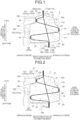
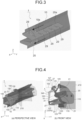
FIG. 1 is a cross-sectional view illustrating a configuration of an internal structure of a side sill according to an embodiment of the present invention (part 1) . -
FIG. 2 is a cross-sectional view illustrating the configuration of the internal structure of the side sill according to the embodiment of the present invention (part 2) . -
FIG. 3 is a diagram illustrating a method for joining a collision energy-absorbing member and a connecting member in the internal structure of the side sill according to the embodiment of the present invention. -
FIG. 4 is a diagram illustrating an example of a deformed state at the time of a side impact in the internal structure of the side sill according to the embodiment of the present invention ((a) perspective view and (b) front view from a front-rear direction of an automotive body). -
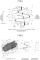
FIG. 5 is a diagram illustrating another aspect of the internal structure of the side sill according to the embodiment of the present invention (part 1). -
FIG. 6 is a diagram illustrating another aspect of the internal structure of the side sill according to the embodiment of the present invention (part 2) ((a) perspective view, (b) A-A cross-sectional view, and (c) B-B cross-sectional view). -
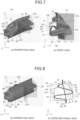
FIG. 7 is a diagram illustrating an example of a deformed state at the time of a side impact in another aspect of the internal structure of the side sill according to the embodiment of the present invention (part 1) ((a) perspective view, (b) front view from a front-rear direction of an automotive body). -
FIG. 8 is a diagram illustrating another aspect of the internal structure of the side sill according to the embodiment of the present invention (part 3). -
FIG. 9 is a diagram illustrating an example of a deformed state at the time of a side impact in another aspect of the internal structure of the side sill according to the embodiment of the present invention (part 2). -
FIG. 10 is a perspective view illustrating a configuration of an internal structure of a side sill according to an invention example in an example ((a) first invention example and (b) second invention example). -
FIG. 11 is a cross-sectional view illustrating a configuration of an internal structure of a side sill according to an invention example in an example ((a) first invention example, (b) second invention example, and (c) third invention example). -
FIG. 12 is a diagram illustrating a maximum crush stroke of a pole that makes a side impact toward the side sill in an example. -
FIG. 13 is a perspective view illustrating a configuration of an internal structure of a side sill according to a comparative example for comparison in an example ((a) first comparative example, (b) second comparative example, and (c) third comparative example). -
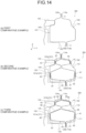
FIG. 14 is a cross-sectional view illustrating a configuration of an internal structure of a side sill according to a comparative example for comparison in an example ((a) first comparative example, (b) second comparative example, and (c) third comparative example). -
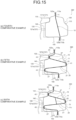
FIG. 15 is a cross-sectional view illustrating a configuration of an internal structure of a side sill according to a comparative example for comparison in an example ((a) fourth comparative example, (b) fifth comparative example, and (c) sixth comparative example). -
FIG. 16 is a cross-sectional view illustrating a configuration of an internal structure of a side sill according to a comparative example for comparison in an example ((a) seventh comparative example, (b) eighth comparative example, and (c) ninth comparative example). -
FIG. 17 is a graph illustrating, in an example, impact performance of side sills according to first to third invention examples and first to ninth comparative examples ((a) relationship between a crashworthiness energy absorption amount and a crush stroke, (b) relationship between a crashworthiness energy absorption amount and a weight of the internal structure of the side sill, and (c) relationship between a crashworthiness energy absorption amount and the number of members constituting the internal structure of the side sill). -
FIG. 18 is a diagram illustrating a side impact test for a side sill of an automotive body. -
FIG. 19 is a diagram illustrating a configuration of a conventional side sill and a vicinity thereof. - Prior to describing an embodiment of the present invention, a configuration of a side sill to which the present invention is applied will be described. In the following description, terms relating to directions and arrangements such as the front-rear direction of the automotive body, the width direction of the automotive body, the vertical direction of the automotive body, the outside of the automotive body, and the inside of the automotive body represent positional relationships in a state of being attached to the automotive body of the automobile. In addition, constituent elements having the same function are denoted by the same reference numerals, and redundant descriptions will be omitted. Further, in the drawings of the present application, an X direction, a Y direction, and a Z direction indicate the front-rear direction of the automotive body, the width direction of the automotive body, and the vertical direction of the automotive body, respectively.
- As illustrated in
FIG. 18 described above, aside sill 100 to which the present invention is applied includes anouter member 110 and aninner member 120. Theouter member 110 extends in the front-rear direction of the automotive body and has a hat-shaped cross section that is open toward the inside of the vehicle in the width direction of the automotive body, and theinner member 120 has a hat-shaped cross section that is open toward the outside of the vehicle in the width direction of the automotive body. - As illustrated in
FIG. 1 , theouter member 110 has a hat-shaped cross section including atop portion 111, avertical wall portion 113, and aflange portion 115. As illustrated inFIG. 1 , theinner member 120 has a hat-shaped cross section including a top portion 121 (firsttop portion 121a and secondtop portion 121b), avertical wall portion 123, and aflange portion 125, and thetop portion 121 and thevertical wall portion 123 are connected via acorner portion 127. - The
outer member 110 and theinner member 120 are joined by aflange portion 115a and aflange portion 125a which are end portions on the upper side of the automotive body and aflange portion 115b and aflange portion 125b which are end portions on the lower side of the automotive body, to thereby form a closed cross-sectional structure. - Further, a
floor cross member 130 is connected to theinner member 120 of theside sill 100 on the upper side of the automotive body, and abattery case 140 is connected to theinner member 120 on the lower side in the vertical direction of the automotive body via a batterylower cross member 150. - The
floor cross member 130, thebattery case 140, and the batterylower cross member 150 are required not to be deformed with a predetermined load bearing capacity even in a side impact in which a crashworthiness load is input to the side surface of theside sill 100 in the width direction of the automotive body. The batterylower cross member 150 is connected to thebattery case 140. - As illustrated in
FIG. 1 as an example, aninternal structure 1 of the side sill according to an embodiment of the present invention is an internal structure of theside sill 100 including theouter member 110 and theinner member 120, and includes a connectingmember 10 and a collision energy-absorbingmember 20. - As illustrated in
FIG. 1 , the connectingmember 10 is disposed to couple theflange portion 115a and theflange portion 125a, and to couple theflange portion 115b and theflange portion 125b, and is formed of one plate member (metal sheet). Theflange portion 115a and theflange portion 125a are end portions on the upper side of the automotive body where theouter member 110 and theinner member 120 are joined, and theflange portion 115b and theflange portion 125b are end portions on the lower side of the automotive body. Further, as illustrated inFIG. 2 , the connectingmember 10 divides the closed cross-sectional structure of theside sill 100 formed by theouter member 110 and theinner member 120 into two of inner and outer parts. As illustrated inFIG. 2 , an outer-side side sill closedcross-sectional structure 31 is formed between the connectingmember 10 and theouter member 110, and an inner-side side sill closedcross-sectional structure 33 is formed between the connectingmember 10 and theinner member 120. - As illustrated in
FIG. 1 , the collision energy-absorbingmember 20 includes a first collision energy-absorbingmember 21 and a second collision energy-absorbingmember 23. - The first collision energy-absorbing
member 21 is a pair of members that forms a linear load transfer path inclined with respect to a horizontal plane of the automotive body in order to transmit a crashworthiness load input to theouter member 110 toward the vicinity of thecorner portions 127 of theinner member 120 in both the upper direction of the automotive body and the lower direction of the automotive body, and absorbs collision energy. - The second collision energy-absorbing
member 23 is a member that is disposed on each of the upper side of the automotive body and the lower side of the automotive body of the first collision energy-absorbingmember 21, is disposed so as to connect theinner member 120 to theflange portion 115 and theflange portion 125, and absorbs collision energy. The second collision energy-absorbingmember 23 may be disposed so as to connect theinner member 120 and the connectingmember 10. - In the present embodiment, the collision energy-absorbing
member 20 is formed by bending one plate member, and is a member in which the first collision energy-absorbingmember 21 and the second collision energy-absorbingmember 23 are integrated. That is, end portions of the pair of first collision energy-absorbingmembers 21 on theouter member 110 side are connected by aload reception portion 25 located near thetop portion 111. End portions of the pair of first collision energy-absorbingmembers 21 on theinner member 120 side are connected to the end portions on theinner member 120 side of the second collision energy-absorbingmember 23 via aload transmission portion 27. Theload transmission portion 27 is connected via theload transmission portion 27 disposed on each of the upper side of the automotive body and the lower side of the automotive body with respect to the vertical center of theinner member 120. As a result, the collision energy-absorbingmember 20 has a substantially M-shaped cross section as a whole by theload reception portion 25, the pair of first collision energy-absorbingmembers 21, theload transmission portion 27, and the second collision energy-absorbingmember 23. - Further, as illustrated in
FIG. 2 , the connectingmember 10 is disposed so as to cross the collision energy-absorbingmember 20 at the first collision energy-absorbingmembers 21. An outer-side EA member closedcross-sectional structure 35 on theouter member 110 side and an inner-side EA member closedcross-sectional structure 37 on theinner member 120 side are formed between the connectingmember 10 and the collision energy-absorbingmember 20. The outer side of theside sill 100 in the width direction of the automotive body constitutes a double closed cross-sectional structure in which the outer-side EA member closedcross-sectional structure 35 is provided inside the outer-side side sill closedcross-sectional structure 31. The inner side of theside sill 100 constitutes a double closed cross-sectional structure in which the inner-side EA member closedcross-sectional structure 37 is provided inside the inner-side side sill closedcross-sectional structure 33. - In the present embodiment, as illustrated in
FIG. 3 for example, the collision energy-absorbingmember 20 and the connectingmember 10 are formed withcuts - In the present embodiment, the
load reception portion 25 is a portion that is joined to the inner surface of thetop portion 111 of theouter member 110 via aresin adhesive 41 and receives a crashworthiness load via theouter member 110 and theresin adhesive 41. - The
load transmission portion 27 is joined to the inner surface of thetop portion 121 of theinner member 120 via aresin adhesive 43. Theload transmission portion 27 is a portion that transmits a crashworthiness load input to theouter member 110 and transmitted via theload reception portion 25 and the first collision energy-absorbingmember 21 to load-bearing members (non-EA members) such as thefloor cross member 130, thebattery case 140, and the batterylower cross member 150. - The
resin adhesive 41 and theresin adhesive 43 preferably have a thickness of 20 mm or less. However, theload reception portion 25 may be directly joined to thetop portion 111 of theouter member 110. Similarly, theload transmission portion 27 may be directly joined to thetop portion 121 of theinner member 120. - The functional effects of the
internal structure 1 of the side sill according to the present embodiment will be described below with reference toFIG. 4 . Note thatFIG. 4 illustrates a state of deformation of the collision energy-absorbingmember 20 and the connectingmember 10 in a case where thepole 210 makes a side impact from the outside of the vehicle in the width direction of the automotive body and a crashworthiness load is input to theside sill 100. - A crashworthiness load is applied to the
side sill 100 from the outer side of the automotive body in the width direction of the automotive body. Then, the crashworthiness load is vertically distributed and transmitted to the load-bearing members (non-EA members) such as thefloor cross member 130 and thebattery case 140 inside the automotive body through the load transfer path that is formed, by the first collision energy-absorbingmember 21, in a straight line to be inclined with respect to the horizontal plane of the automotive body. - At this time, as illustrated in
FIG. 4 , the upper portion of the collision energy-absorbingmember 20 is supported by the upper portion of thefloor cross member 130 or thebattery case 140. The lower portion of the collision energy-absorbingmember 20 is supported by the lower portion of thebattery case 140 or the batterylower cross member 150. Then, the first collision energy-absorbingmember 21 forming the load transfer path on theouter member 110 side is crushed to absorb the collision energy. The outer side of theside sill 100 in the width direction of the automotive body can enhance the crashworthiness energy absorption amount because of the double closed cross-sectional structure (seeFIG. 2 ) in which the outer-side EA member closedcross-sectional structure 35 is provided inside the outer-side side sill closedcross-sectional structure 31. - Thereafter, the first collision energy-absorbing
member 21 and the second collision energy-absorbingmember 23 on theinner member 120 side are crushed while being supported by thefloor cross member 130 and thebattery case 140, and the collision energy is further absorbed. The inner side of theside sill 100 can enhance the crashworthiness energy absorption amount because of the double closed cross-sectional structure (seeFIG. 2 ) in which the inner-side EA member closedcross-sectional structure 37 is provided inside the inner-side side sill closedcross-sectional structure 33. - After the first collision energy-absorbing
member 21 and the second collision energy-absorbingmember 23 are crushed and bent, theload transmission portion 27 is disconnected from the inner surface of thetop portion 121 of theinner member 120. Thereafter, theload transmission portion 27 is shifted to each of the upper side of the automotive body and the lower side of the automotive body, and abuts on thecorner portions 127 on the upper side of the automotive body and the lower side of the automotive body of thetop portion 121 in theinner member 120 or the vicinity of thecorner portions 127. The first collision energy-absorbingmember 21 and the second collision energy-absorbingmember 23 which have been crushed and bent are tensioned to maintain a resistance force against a collision deformation in the width direction of the automotive body. Therefore, the first collision energy-absorbingmember 21 and the second collision energy-absorbingmember 23 continue to hold the collision energy absorptive properties even after being crushed and bent. Since thecorner portions 127 or the vicinity thereof in theinner member 120 are supported by the bent first collision energy-absorbingmember 21 and second collision energy-absorbingmember 23, theinner member 120 continues to maintain the hat-shaped cross section without being completely crushed. This deformed state is achieved by a structure in which the first collision energy-absorbingmember 21 is inclined with respect to the horizontal plane of the automotive body and is connected from theload reception portion 25 toward the vicinity of thecorner portions 127. - In that case, the end portion of the collision energy-absorbing
member 20 on the upper side of the automotive body and the end portion thereof on the lower side of the automotive body are joined to the connectingmember 10. This prevents the development of the bending ridgeline of the substantially M-shaped cross section of the collision energy-absorbingmember 20, and crushes the linear first collision energy-absorbingmember 21 and the linear second collision energy-absorbingmember 23 to enhance the energy absorption efficiency. - As described above, the first collision energy-absorbing
member 21 forms a linear load transfer path from theload reception portion 25 toward theload transmission portion 27. As a result, the crashworthiness load input to theouter member 110 is efficiently transmitted to the load-bearing members such as thefloor cross member 130 and thebattery case 140, crushing the first collision energy-absorbingmember 21 is accelerated, and the absorption efficiency of the collision energy can be enhanced. - In addition, end portions 11 (11a, 11b) of the connecting
member 10 in the vertical direction of the automotive body are connected to theflange portion 115a and theflange portion 125a on the upper side of the automotive body of theside sill 100 and theflange portion 115b and theflange portion 125b on the lower side of the automotive body of theside sill 100. This prevents the cross section of theside sill 100 from opening vertically and collapsing (prevention of cross-section collapsing) in the event of a side impact with the automotive body to thereby enhance the impact strength. - As a result, it is possible to prevent a reduction in the absorption efficiency of the collision energy due to the cross-section collapsing of the
side sill 100. - Further, the first collision energy-absorbing
member 21 is divided into theouter member 110 side and theinner member 120 side by the connectingmember 10. Then, the two closed cross-sectional structures (outer-side EA member closedcross-sectional structure 35 and inner-side EA member closedcross-sectional structure 37, seeFIG. 2 ) are formed inside theside sill 100. Since the first collision energy-absorbingmember 21 is divided by the connectingmember 10, the wavelength of buckling of the first collision energy-absorbingmember 21 can be shortened. This increases the impact strength of the first collision energy-absorbingmember 21, and a larger load can be transmitted. - Further, in the
internal structure 1 of the side sill according to the present embodiment, the simple structure using the connectingmember 10 and the collision energy-absorbingmember 20 can reduce the number of components, leading to the weight reduction. - The vicinity of the
corner portions 127 is a portion where theload transmission portion 27 of the collision energy-absorbingmember 20 abuts on the inner surface of theinner member 120 directly or via theresin adhesive 43. Specifically, the vicinity of thecorner portions 127 is a portion where thefloor cross member 130 which is a frame structure member of the automotive body and thebattery case 140 are connected to the automotive body side of theinner member 120. In the present embodiment, as illustrated inFIG. 1 , the vicinity of thecorner portions 127 refers to a region extending from thetop portion 121 to thecorner portion 127a of theinner member 120 on the upper side of the automotive body and a region extending from thetop portion 121 to thecorner portion 127b of theinner member 120 on the lower side of the automotive body. However, the vicinity of thecorner portions 127 is not limited to the regions extending from thetop portion 121 to thecorner portions 127, and may be a region extending from thecorner portions 127 to thevertical wall portion 123. Theload transmission portion 27 is a portion that transmits a crashworthiness load to the load-bearing members (non-EA members). The upper limit of the length of theload transmission portion 27 in the vertical direction of the automotive body is the length of the load-bearing members (non-EA members) connected to theinner member 120 of theside sill 100 in the vertical direction of the automotive body, and the length of theload transmission portion 27 in the vertical direction of the automotive body is preferably at least about one third of the length of the load-bearing members (non-EA members) in the vertical direction of the automotive body. - In the foregoing description, the collision energy-absorbing
member 20 is formed by bending one plate member, and the first collision energy-absorbingmember 21 is integrated with the second collision energy-absorbingmember 23. However, as illustrated inFIG. 5 , a collision energy-absorbing member according to the present invention may be a collision energy-absorbingmember 50 formed of separate plate members such as a hatcross-sectional member 51 on theouter member 110 side and two hatcross-sectional members 53 that are arranged side by side in the vertical direction of the automotive body on theinner member 120 side. - As illustrated in
FIG. 5 , the hatcross-sectional member 51 has a hat-shaped cross section that is open toward the inside of the vehicle in the width direction of the automotive body. The hatcross-sectional member 51 includes atop portion 51a joined to the inner surface of thetop portion 111 of theouter member 110 via theresin adhesive 41, a pair ofvertical wall portions 51b inclined with respect to the horizontal plane of the automotive body, and aflange portion 51c joined to the connectingmember 10. - Further, as exemplified in
FIG. 5 , the hatcross-sectional member 53 has a hat-shaped cross section that is open toward the outside of the vehicle in the width direction of the automotive body. The hatcross-sectional member 53 includes atop portion 53a joined to the inner surface of thetop portion 121 of theinner member 120 via theresin adhesive 43,vertical wall portions 53b inclined with respect to the horizontal plane of the automotive body, and aflange portion 53c joined to the connectingmember 10. - Then, the
vertical wall portions 51b of the hatcross-sectional member 51 and the twovertical wall portions 53b of the two hatcross-sectional members 53 on the center side in the vertical direction of the automotive body form the first collision energy-absorbingmember 21. In addition, the twovertical wall portions 53b of the two hatcross-sectional members 53 on the upper side of the automotive body and the lower side of the automotive body form the second collision energy-absorbingmember 23. - Note that the two hat
cross-sectional members 53 illustrated inFIG. 5 may be formed by bending one plate member and integrated. - In the
internal structure 1 of the side sill according to the present embodiment, the connectingmember 10 is formed of one plate member, and is joined to the first collision energy-absorbingmember 21 to divide the load transfer path into theouter member 110 side and theinner member 120 side. However, as illustrated inFIG. 6 , a connectingmember 15 according to the present invention may include a plurality of strip-shaped plate members extending in the vertical direction of the automotive body, and may be disposed so as to penetrate the first collision energy-absorbingmember 21 and the second collision energy-absorbingmember 23. - Even with the connecting
member 15 including the strip-shaped plate members, as illustrated inFIG. 7 , it is possible to prevent the closed cross section of theside sill 100 from opening vertically, and it is possible to axially crush the first collision energy-absorbingmember 21 efficiently and prevent a reduction in the absorption efficiency of the collision energy. - Further, as illustrated in
FIG. 8 , in the first collision energy-absorbingmember 21, a groove-shaped portion (for example, a bead portion 29) is preferably formed along the load transfer path. - In order to improve the load transfer and the absorption of collision energy by the first collision energy-absorbing
member 21, it is necessary to increase deformation energy (deformation resistance) of the first collision energy-absorbingmember 21. As illustrated inFIG. 9 , the first collision energy-absorbingmember 21 is provided with thebead portion 29, which increases the deformation resistance of the first collision energy-absorbingmember 21 and increases the deformation energy. As a result, the impact strength of the first collision energy-absorbingmember 21 can be raised, leading to the improvement in the crashworthiness energy absorption amount. - Even in the
internal structure 1 of the side sill having the strip-shaped connectingmember 15 as illustrated inFIG. 6 , the crashworthiness load and the crashworthiness energy absorption amount can be improved by forming thebead portion 29 in the first collision energy-absorbingmember 21. Also in this case, thebead portion 29 may be divided in the direction along the load transfer path. In this manner, the wavelength of buckling can be controlled by dividing the bead portion and adjusting the length of the bead portion in the direction along the load transfer path. - In the foregoing description, an electric automobile is assumed in which the
battery case 140 as the load-bearing member is connected to theinner member 120 of theside sill 100. However, the present invention is not limited to the internal structure of the side sill of the electric automobile, and can be preferably applied to one in which a load-bearing member such as a floor cross member is connected to the upper side of the automotive body and the lower side of the automotive body in the inner member of the side sill. - A specific test was conducted to verify the functional effects of the internal structure of the side sill according to the present invention, and the results are described below.
- In the present example, as illustrated in
FIGS. 10 and11 , a side impact test in which thepole 210 collides, from the outside in the automotive body width direction, with an automotive bodypartial model 200 including theside sill 100, thefloor cross member 130 and thebattery case 140 connected to theside sill 100, was conducted to evaluate the impact performance. Theside sill 100 includes theinternal structure 1 of the side sill including the connectingmember 10 and the collision energy-absorbingmember 20. - As described in the embodiment of the present invention, the
side sill 100 includes theouter member 110 and theinner member 120, and the hat-shaped cross section of theouter member 110 and the hat-shaped cross section of theinner member 120 are opened to face each other. Theouter member 110 and theinner member 120 form a closed cross-sectional structure in which theflange portion 115a of theouter member 110 and theflange portion 125a of theinner member 120 are joined, and theflange portion 115b of theouter member 110 and theflange portion 125b of theinner member 120 are joined. In the present example, as illustrated inFIGS. 10 and11 , the automotive bodypartial model 200 including theinternal structure 1 of the side sill satisfying the constituent features of the present invention was defined as the first to third invention examples. - As illustrated in
FIGS. 10(a) and11(a) , the first invention example includes the connectingmember 10 integrally formed, and the collision energy-absorbingmember 20 integrally formed in a substantially M-shaped cross-sectional shape from one plate member. - As illustrated in
FIGS. 10(b) and11(b) , the second invention example includes the connectingmember 10 integrally formed, and the collision energy-absorbingmember 20 integrally formed in a substantially M-shaped cross-sectional shape from one plate member. In the second invention example, thebead portion 29 divided by the connectingmember 10 is formed in the first collision energy-absorbingmember 21 of the collision energy-absorbingmember 20. - As illustrated in
FIG. 11(c) , the third invention example includes the connectingmember 10 integrally formed, and the collision energy-absorbingmember 20 integrally formed in a substantially M-shaped cross-sectional shape from one plate member. In the third invention example, thebead portion 29 extending from theouter member 110 side to theinner member 120 side without being divided by the connectingmember 10 is formed in the first collision energy-absorbingmember 21 of the collision energy-absorbingmember 20. - Here, the collision energy-absorbing
member 20 in each of the first to third invention examples has oneload reception portion 25 that abuts on the inner surface of thetop portion 111 of theouter member 110 via theresin adhesive 41, and has twoload transmission portions 27 that abut on the inner surface of thetop portion 121 of theinner member 120 via theresin adhesive 43. - In the first to third invention examples, each of the
side sill 100, the connectingmember 10, and the collision energy-absorbingmember 20 is prepared using a 1.5 GPa-class high-tensile steel sheet having a sheet thickness of 1.6 mm. - In the present example, the intrusion amount (crush stroke) of the
pole 210 having a diameter of 250 mm into theside sill 100 when thepole 210 makes a side impact on the extension of thefloor cross member 130 in the longitudinal direction and on theouter member 110 side of theside sill 100, and the crashworthiness energy absorption amount at the time of the side impact of thepole 210 were obtained. Then, an evaluation as to whether or not the intrusion amount of thepole 210 was equal to or less than a maximum crush stroke Lmax illustrated inFIG. 12 was conducted. Here, the maximum crush stroke Lmax is a horizontal distance from thetop portion 111 of theouter member 110 to the batterylower cross member 150 in the width direction of the automotive body. - Note that the actual side impact test using the
pole 210 is conducted by causing the automotive body of the automobile to collide with the fixedpole 210 with kinetic energy. However, in the side impact test using the automotive bodypartial model 200 in the present example, it is replaced with an event of colliding thepole 210 having predetermined kinetic energy with theside sill 100. Here, the kinetic energy of thepole 210 was set to 22 kJ. - For comparison, as illustrated in
FIGS. 13 to 16 , an automotive bodypartial model 300 having an internal structure of a side sill outside the scope of the present invention was used in a comparative example, and was compared and examined with that in the invention examples. - As illustrated in
FIGS. 13(a) and14(a) , the first comparative example is an example in which neither the connectingmember 10 nor the collision energy-absorbing member 20 (seeFIGS. 10 and11 ) according to the present invention is disposed inside theside sill 100. - As illustrated in
FIGS. 13(b) and14(b) , andFIGS. 13(c) and14(c) , the second and third comparative examples are examples in which two collision energy-absorbingmembers side sill 100. In the second and third comparative examples, twoload reception portions 65 that abut on the inner surface of thetop portion 111 of theouter member 110 are provided, and twoload transmission portions 67 that abut on the inner surface of thetop portion 121 of theinner member 120 are provided. - Further, as with the second and third invention examples, in the third comparative example, a
bead portion 69 extending along the vehicle width direction was provided on the upper surface sides of the collision energy-absorbingmember 61 and the collision energy-absorbingmember 63. - As illustrated in
FIG. 15 , in the fourth to sixth comparative examples, a part of the connectingmember 10 or the collision energy-absorbingmember 20 according to the first invention example was disposed. - As illustrated in
FIG. 15(a) , in the fourth comparative example, only the connectingmember 10 of the first invention example was disposed. As illustrated inFIG. 15(b) , in the fifth comparative example, only the collision energy-absorbingmember 20 of the first invention example was disposed. As illustrated inFIG. 15(c) , the sixth comparative example is an example in which a part of the connectingmember 10 in the first invention example was left as a connectingmember 71 only between the first collision energy-absorbingmember 21 on the upper side of the automotive body and the first collision energy-absorbingmember 21 on the lower side of the automotive body, and the inner-side EA member closedcross-sectional structure 37 in the first invention example was removed. - Here, in the fifth and sixth comparative examples, as with the first invention example, one
load reception portion 25 that abuts on the inner surface of thetop portion 111 of theouter member 110 is provided, and twoload transmission portions 27 that abut on the inner surface of thetop portion 121 of theinner member 120 are provided. - As illustrated in
FIG. 16 , in the seventh to ninth comparative examples, instead of the collision energy-absorbingmember 20 having a substantially M-shaped cross section, a collision energy-absorbingmember 80 that has a hat-shaped cross section and includes atop portion 81, avertical wall portion 83, and aflange portion 85 is used. In the seventh to ninth comparative examples, thevertical wall portion 83 which is a load transfer path from theouter member 110 to theinner member 120 is parallel to the horizontal plane of the automotive body and is not inclined. - As illustrated in
FIG. 16(a) , in the seventh comparative example, one collision energy-absorbingmember 80 having a hat-shaped cross section was disposed without using the connectingmember 10. In the seventh comparative example, thetop portion 81 of the collision energy-absorbingmember 80 is joined to the inner surface of thetop portion 111 of theouter member 110 as one load reception portion, a pair of theflange portions 85 is joined to the inner surface of the firsttop portion 121a of theinner member 120 as the load transmission portion, and a pair of thevertical wall portions 83 is used as the load transfer path. - As illustrated in
FIG. 16(b) , in the eighth comparative example, one collision energy-absorbingmember 80 having a hat-shaped cross section was disposed on each of theouter member 110 side and theinner member 120 side in the closed cross section in theside sill 100 partitioned by the connectingmember 10. Thetop portion 81 of the collision energy-absorbingmember 80 on theinner member 120 side is joined to the inner surface of thetop portion 121 of theinner member 120 as one load transmission portion. - As illustrated in
FIG. 16(b) , in the ninth comparative example, a total of three collision energy-absorbingmembers 80, one on theouter member 110 side and two on theinner member 120 side, were disposed in the closed cross section in theside sill 100 partitioned by the connectingmember 10. Thetop portions 81 of the two collision energy-absorbingmembers 80 on theinner member 120 side are joined to the inner surface of thetop portion 121 of theinner member 120 as two load transmission portions. - In the seventh to ninth comparative examples, the
top portion 81 of the collision energy-absorbingmember 80 on theouter member 110 side abuts on the inner surface of thetop portion 111 of theouter member 110 as one load reception portion. - The relationship between the structures of the collision energy-absorbing member and the connecting member in the first to third invention examples and the first to ninth comparative examples is indicated in Table 1, and the results of the impact evaluation are indicated in Table 2.
Table 1 Collision energy-absorbing member Presence or absence of connecting member Bead portion One or more load reception portions outside vehicle (outer member side) Two or more load transmission portions inside vehicle (inner member side) Load transfer path Presence or absence Cut First invention example ○ ○ Inclined ○ - - Second invention example ○ ○ Inclined ○ ○ - Third invention example ○ ○ Inclined ○ ○ ○ First comparative example ○ - Inclined - - - Second comparative example ○ ○ Inclined - - - Third comparative example ○ ○ Inclined - ○ - Fourth comparative example ○ - Inclined ○ - - Fifth comparative example ○ ○ Inclined - - - Sixth comparative example ○ ○ Inclined (○ Partial) - - Seventh comparative example ○ ○ Level - - - Eighth comparative example ○ - Level ○ - - Ninth comparative example ○ ○ Level ○ - - Table 2 Crush stroke [mm] Crashworthiness energy absorption amount [kJ] Battery protection Plate thickness [mm] Steel plate strength Weight [kg] Number of parts First invention example 99 19.3 ○ 1.6 1.5 GPa-class 5.8 2 Second invention example 84 18.8 ○ 1.6 1.5 GPa- class 6.0 2 Third invention example 85 19.0 ○ 1.6 1.5 GPa- class 5.9 2 First comparative example 105 9.5 × 1.6 1.5 GPa- class 0.0 0 Second comparative example 105 12.6 × 1.6 1.5 GPa- class 5.8 2 Third comparative example 105 15.2 × 1.6 1.5 GPa-class 6.1 2 Fourth comparative example 105 11.0 × 1.6 1.5 GPa-class 1.7 1 Fifth comparative example 105 12.2 × 1.6 1.5 GPa- class 4.1 1 Sixth comparative example 105 10.5 × 1.6 1.5 GPa- class 2.2 2 Seventh comparative example 105 11.5 × 1.6 1.5 GPa-class 2.1 1 Eighth comparative example 105 12.1 × 1.6 1.5 GPa-class 5.9 3 Ninth comparative example 105 12.8 × 1.6 1.5 GPa- class 6.3 4 - Table 2 shows that in each of the first to third invention examples, the crush stroke was less than the maximum crush stroke Lmax (= 105 mm), and the crashworthiness load input to the
outer member 110 was efficiently transmitted to theinner member 120 side. - On the other hand, in each of the first to ninth comparative examples, the crush stroke reaches the maximum crush stroke Lmax (= 105 mm). In the first to ninth comparative examples, the collision energy is not sufficiently absorbed, and there is a concern that a crashworthiness load equal to or greater than the loading bearing capacity acts on the
floor cross member 130 and thebattery case 140 to collapse (see "BATTERY PROTECTION" in Table 2). -
FIG. 17(a) illustrates the relationship between the crashworthiness energy absorption amount and the crush stroke among the results of the side impact test indicated in Table 2. In each of the first to ninth comparative examples, the maximum crush stroke (Lmax = 105 mm) was reached, and the crashworthiness energy absorption amount was 9.5 to 15.2 kJ (average 11.9 kJ). - In contrast, in the first to third invention examples, the collision energy-absorbing
member 20 absorbed the collision energy (= 22 kJ) of thepole 210 before the crush stroke of thepole 210 reaches the maximum crush stroke Lmax (= 105 mm). The crashworthiness energy absorption amount in the first to third invention examples was 18.8 to 19.3 kJ (average 19.0 kJ), which was improved to two times that of the first comparative example (9.5 kJ for a case where no collision energy-absorbing member is disposed in the side sill) and improved to about 1.6 times that of the second to ninth comparative examples (average 12.2 kJ). Since the value in each of the first to third invention examples is equal to or less than the prescribed crush stroke, it is considered that the collision energy absorptive properties are higher than these values. -
FIG. 17(b) illustrates the relationship between the crashworthiness energy absorption amount and the weights of the connecting member and the collision energy-absorbing member provided inside theside sill 100 among the results of the side impact test indicated in Table 2. According to the results illustrated inFIG. 17(b) , it is found that in the first to ninth comparative examples, the crashworthiness energy absorption amount also increases as the weight of the collision energy-absorbing member and/or the connecting member increases. - A comparison is made between the results of the second, third, eighth, and ninth comparative examples in which weights (about 6 kg or so) equivalent to the weights (5.8 to 6.0 kg) of the collision energy-absorbing member and the connecting member in the first to third invention examples, and the results of the first to third invention examples. Then, the crashworthiness energy absorption amounts in the first to third invention examples were 19.0 kJ (18.8 to 19.3 kJ) on average, which was 44% higher than 13.2 kJ (12.1 to 15.2 kJ) on average of the crashworthiness energy absorption amounts in the second, third, eighth, and ninth comparative examples, and the results that the crashworthiness energy absorption amounts (mass efficiency) per unit weight of the connecting member and the collision energy-absorbing member were high were obtained. This is because in the first to third invention examples, the collision energy-absorbing
member 20 disposed in theside sill 100 was efficiently crushed at the time of a side impact, so that the absorption efficiency of the collision energy was enhanced. -
FIG. 17(c) illustrates the relationship between the crashworthiness energy absorption amount and the number of components related to the internal structure of the side sill among the results of the side impact test indicated in Table 2. According to the results illustrated inFIG. 17(c) , it was shown that although the simple structure is used in the first to third invention examples in which the number of collision energy-absorbing members and the number of connecting members disposed inside theside sill 100 are reduced, the weight reduction can be achieved while a high crashworthiness energy absorption amount is kept. - As described above, according to the internal structure of the side sill of the present invention, it has been shown that even with a simple structure in which the number of components is small, the weight reduction can be achieved while ensuring high collision energy absorptive performance.
- According to the present invention, it is possible to provide an internal structure of a side sill that is capable of preventing an excessive input load from the side sill to a specific component such as a battery case and preventing an increase in the number of components and manufacturing cost while having sufficient collision energy absorptive properties.
-
- 1
- INTERNAL STRUCTURE OF SIDE SILL
- 10
- CONNECTING MEMBER
- 10a
- CUT
- 11
- END PORTION
- 15
- CONNECTING MEMBER
- 20
- COLLISION ENERGY-ABSORBING MEMBER
- 20a
- CUT
- 21
- FIRST COLLISION ENERGY-ABSORBING MEMBER
- 23
- SECOND COLLISION ENERGY-ABSORBING MEMBER
- 25
- LOAD RECEPTION PORTION
- 27
- LOAD TRANSMISSION PORTION
- 29
- BEAD PORTION
- 31
- OUTER-SIDE SIDE SILL CLOSED CROSS-SECTIONAL STRUCTURE
- 33
- INNER-SIDE SIDE SILL CLOSED CROSS-SECTIONAL STRUCTURE
- 35
- OUTER-SIDE EA MEMBER CLOSED CROSS-SECTIONAL STRUCTURE
- 37
- INNER-SIDE EA MEMBER CLOSED CROSS-SECTIONAL STRUCTURE
- 41
- RESIN ADHESIVE
- 43
- RESIN ADHESIVE
- 50
- COLLISION ENERGY-ABSORBING MEMBER
- 51
- HAT CROSS-SECTIONAL MEMBER
- 51a
- TOP PORTION
- 51b
- VERTICAL WALL PORTION
- 51c
- FLANGE PORTION
- 53
- HAT CROSS-SECTIONAL MEMBER
- 53a
- TOP PORTION
- 53b
- VERTICAL WALL PORTION
- 53c
- FLANGE PORTION
- 61
- COLLISION ENERGY-ABSORBING MEMBER
- 63
- COLLISION ENERGY-ABSORBING MEMBER
- 65
- LOAD RECEPTION PORTION
- 67
- LOAD TRANSMISSION PORTION
- 69
- BEAD PORTION
- 71
- CONNECTING MEMBER
- 80
- COLLISION ENERGY-ABSORBING MEMBER
- 81
- TOP PORTION
- 83
- VERTICAL WALL PORTION
- 85
- FLANGE PORTION
- 100
- SIDE SILL
- 110
- OUTER MEMBER
- 111
- TOP PORTION
- 113
- VERTICAL WALL PORTION
- 115
- FLANGE PORTION
- 115a
- FLANGE PORTION
- 115b
- FLANGE PORTION
- 120
- INNER MEMBER
- 121
- TOP PORTION
- 121a
- FIRST TOP PORTION
- 121b
- SECOND TOP PORTION
- 123
- VERTICAL WALL PORTION
- 125
- FLANGE PORTION
- 125a
- FLANGE PORTION
- 125b
- FLANGE PORTION
- 127
- CORNER PORTION
- 127a
- CORNER PORTION
- 127b
- CORNER PORTION
- 130
- FLOOR CROSS MEMBER
- 140
- BATTERY CASE
- 150
- BATTERY LOWER CROSS MEMBER
- 200
- AUTOMOTIVE BODY PARTIAL MODEL (INVENTION EXAMPLE)
- 210
- POLE
- 300
- AUTOMOTIVE BODY PARTIAL MODEL (COMPARATIVE EXAMPLE)
Claims (7)
- An internal structure of a side sill, comprising:an outer member extending in a front-rear direction of an automotive body and having a hat-shaped cross section that is open toward an inside of a vehicle in a width direction of the automotive body;an inner member having a hat-shaped cross section that is open toward an outside of the vehicle in the width direction of the automotive body;a closed cross-sectional structure formed by joining an end portion of each of the outer member and the inner member on an upper side of the automotive body and an end portion of each of the outer member and the inner member on a lower side of the automotive body while an open side of the outer member and an open side of the inner member facing each other;a connecting member disposed so as to connect the end portion of each of the outer member and the inner member on the upper side of the automotive body and the end portion of each of the outer member and the inner member on the lower side of the automotive body; anda collision energy-absorbing member configured to absorb collision energy while transmitting a crashworthiness load input to the outer member to the inner member side, the collision energy-absorbing member including:a pair of first collision energy-absorbing members configured to form a linear load transfer path inclined with respect to a horizontal plane of the automotive body to transmit the crashworthiness load input to the outer member toward a corner portion of the inner member in both an upper direction of the automotive body and a lower direction of the automotive body or a vicinity of the corner portion, and absorb the collision energy; anda second collision energy-absorbing member disposed in the first collision energy-absorbing member on each of an upper side of the automotive body and a lower side of the automotive body, and configured to connect the inner member and the connecting member or the end portion, and absorb the collision energy.
- The internal structure of the side sill according to claim 1, wherein the collision energy-absorbing member is formed by bending one plate member, and is a member in which the first collision energy-absorbing member and the second collision energy-absorbing member are integrated.
- The internal structure of the side sill according to claim 1, wherein the first collision energy-absorbing member has a hat-shaped cross section that is open toward the inside of the vehicle in the width direction of the automotive body, and includes a pair of vertical wall portions inclined with respect to the horizontal plane of the automotive body.
- The internal structure of the side sill according to claim 1, whereinthe second collision energy-absorbing member includes two members having a hat-shaped cross section that are open toward the outside of the vehicle in the width direction of the automotive body and arranged side by side in a vertical direction of the automotive body,two vertical wall portions on a center side in the vertical direction of the automotive body, among vertical wall portions of the two members having a hat-shaped cross section, form a part of the first collision energy-absorbing member, andtwo vertical wall portions on the upper direction of the automotive body and the lower direction of the automotive body, among the vertical wall portions of the two members having a hat-shaped cross section, form the second collision energy-absorbing member.
- The internal structure of the side sill according to any one of claims 1 to 4, wherein the connecting member is made of one plate member, and is joined to the first collision energy-absorbing member to divide the load transfer path into the outer member side and the inner member side.
- The internal structure of the side sill according to any one of claims 1 to 4, wherein the connecting member includes a plurality of strip-shaped plate members extending in the vertical direction of the automotive body, and is disposed so as to penetrate the first collision energy-absorbing member and the second collision energy-absorbing member.
- The internal structure of the side sill according to any one of claims 1 to 6, wherein the first collision energy-absorbing member has a groove-shaped portion formed along the load transfer path.
Applications Claiming Priority (2)
| Application Number | Priority Date | Filing Date | Title |
|---|---|---|---|
| JP2021188333A JP7255657B1 (en) | 2021-11-19 | 2021-11-19 | Side sill internal structure |
| PCT/JP2022/031227 WO2023089887A1 (en) | 2021-11-19 | 2022-08-18 | Internal structure for side sills |
Publications (2)
| Publication Number | Publication Date |
|---|---|
| EP4410640A1 true EP4410640A1 (en) | 2024-08-07 |
| EP4410640A4 EP4410640A4 (en) | 2025-01-29 |
Family
ID=85872880
Family Applications (1)
| Application Number | Title | Priority Date | Filing Date |
|---|---|---|---|
| EP22895175.2A Pending EP4410640A4 (en) | 2021-11-19 | 2022-08-18 | Internal structure for side sills |
Country Status (7)
| Country | Link |
|---|---|
| US (1) | US20250242866A1 (en) |
| EP (1) | EP4410640A4 (en) |
| JP (1) | JP7255657B1 (en) |
| KR (1) | KR20240089588A (en) |
| CN (1) | CN118265648A (en) |
| MX (1) | MX2024005991A (en) |
| WO (1) | WO2023089887A1 (en) |
Families Citing this family (5)
| Publication number | Priority date | Publication date | Assignee | Title |
|---|---|---|---|---|
| MX2024007134A (en) | 2022-01-07 | 2024-06-24 | Shape Corp | OSCILLATING SHAFT INSERT PIECE WITH CORRUGATED STRUCTURE. |
| KR20240092459A (en) * | 2022-12-14 | 2024-06-24 | 현대자동차주식회사 | Side sill of vehicle |
| JP2025080183A (en) * | 2023-11-13 | 2025-05-23 | トヨタ自動車株式会社 | Vehicle underbody structure |
| JP2025095483A (en) * | 2023-12-14 | 2025-06-26 | マツダ株式会社 | Vehicle underbody structure |
| US12617469B2 (en) | 2024-03-22 | 2026-05-05 | Honda Motor Co., Ltd. | Reinforcement assembly for a side sill of a vehicle |
Family Cites Families (9)
| Publication number | Priority date | Publication date | Assignee | Title |
|---|---|---|---|---|
| JPH0457291U (en) | 1990-09-18 | 1992-05-15 | ||
| EP2251250A1 (en) * | 2009-05-05 | 2010-11-17 | Sika Technology AG | Bonding with adhesive beads or plots |
| US9758193B2 (en) * | 2015-02-10 | 2017-09-12 | Honda Motor Co., Ltd. | Structural reinforcement member for a vehicle body |
| JP6734709B2 (en) | 2016-06-23 | 2020-08-05 | 本田技研工業株式会社 | Underbody structure |
| JP6757291B2 (en) | 2017-05-19 | 2020-09-16 | 本田技研工業株式会社 | Body undercarriage |
| KR102775893B1 (en) * | 2018-12-28 | 2025-02-28 | 오토테크 엔지니어링 에스.엘. | Vehicle rocker structure and method of obtaining it |
| WO2020225590A1 (en) * | 2019-05-07 | 2020-11-12 | Arcelormittal | Side sill part for an automotive vehicle |
| US12060111B2 (en) * | 2019-09-25 | 2024-08-13 | Posco | Side sill for vehicle |
| JP6964641B2 (en) * | 2019-10-18 | 2021-11-10 | 本田技研工業株式会社 | Car side sill structure |
-
2021
- 2021-11-19 JP JP2021188333A patent/JP7255657B1/en active Active
-
2022
- 2022-08-18 US US18/704,178 patent/US20250242866A1/en active Pending
- 2022-08-18 MX MX2024005991A patent/MX2024005991A/en unknown
- 2022-08-18 KR KR1020247015615A patent/KR20240089588A/en active Pending
- 2022-08-18 CN CN202280076174.9A patent/CN118265648A/en active Pending
- 2022-08-18 WO PCT/JP2022/031227 patent/WO2023089887A1/en not_active Ceased
- 2022-08-18 EP EP22895175.2A patent/EP4410640A4/en active Pending
Also Published As
| Publication number | Publication date |
|---|---|
| KR20240089588A (en) | 2024-06-20 |
| JP2023075430A (en) | 2023-05-31 |
| MX2024005991A (en) | 2024-05-30 |
| EP4410640A4 (en) | 2025-01-29 |
| WO2023089887A1 (en) | 2023-05-25 |
| US20250242866A1 (en) | 2025-07-31 |
| JP7255657B1 (en) | 2023-04-11 |
| CN118265648A (en) | 2024-06-28 |
Similar Documents
| Publication | Publication Date | Title |
|---|---|---|
| US20250242866A1 (en) | Internal structure of side sill | |
| US9981541B2 (en) | Protection structure of battery module mounted in rear of vehicle body | |
| US9221412B2 (en) | Front vehicle body structure | |
| CN102741106B (en) | For crash module and the corresponding guideway vehicle of guideway vehicle | |
| JP2024026492A (en) | Reinforced frame for a battery pack of an electric or hybrid vehicle, reinforced battery pack, and method for assembling the battery pack | |
| KR20210145270A (en) | side sill parts for automobiles | |
| US11046364B2 (en) | Front support for vehicle | |
| WO2016148635A1 (en) | Progressive crash box member and its arrangement | |
| US20180065671A1 (en) | Rear vehicle-body structure of vehicle | |
| CN108495777A (en) | Front part structure of vehicle | |
| JP2007191008A (en) | Automobile side sill | |
| EP3386847B1 (en) | Vehicle underbody structure comprising a reinforcement element between a longitudinal beam and a lowerside sill part | |
| WO2023189029A1 (en) | Vehicle body structure, and method for designing vehicle body structure | |
| EP4230508A1 (en) | Vehicle body lower structure of automobile | |
| EP3932750B1 (en) | Structural member for vehicle | |
| CN101481989A (en) | Vehicle door anti-collision rod and vehicle door using the same | |
| EP3875351A1 (en) | Member and vehicle skeleton | |
| CN117533417A (en) | New energy automobile structure with low cost, high endurance and high side collision safety | |
| JP7609214B1 (en) | Electric vehicle underbody structure | |
| Nivesh et al. | Design of the BIW Structure for Battery Pack Protection in Case of Side Pole Impact | |
| CN219154586U (en) | Vehicle body frame structure and vehicle | |
| CN215245106U (en) | Side member assembly of a vehicle and vehicle having the same | |
| US20250313274A1 (en) | Front side vehicle body for a vehicle | |
| JP4394894B2 (en) | Rear floor structure | |
| EP4015314A1 (en) | Crash extension for crash management system |
Legal Events
| Date | Code | Title | Description |
|---|---|---|---|
| STAA | Information on the status of an ep patent application or granted ep patent |
Free format text: STATUS: THE INTERNATIONAL PUBLICATION HAS BEEN MADE |
|
| PUAI | Public reference made under article 153(3) epc to a published international application that has entered the european phase |
Free format text: ORIGINAL CODE: 0009012 |
|
| STAA | Information on the status of an ep patent application or granted ep patent |
Free format text: STATUS: REQUEST FOR EXAMINATION WAS MADE |
|
| 17P | Request for examination filed |
Effective date: 20240503 |
|
| AK | Designated contracting states |
Kind code of ref document: A1 Designated state(s): AL AT BE BG CH CY CZ DE DK EE ES FI FR GB GR HR HU IE IS IT LI LT LU LV MC MK MT NL NO PL PT RO RS SE SI SK SM TR |
|
| A4 | Supplementary search report drawn up and despatched |
Effective date: 20250103 |
|
| RIC1 | Information provided on ipc code assigned before grant |
Ipc: B62D 25/02 20060101ALI20241220BHEP Ipc: B62D 21/15 20060101ALI20241220BHEP Ipc: B62D 25/20 20060101AFI20241220BHEP |
|
| DAV | Request for validation of the european patent (deleted) | ||
| DAX | Request for extension of the european patent (deleted) |