EP4410569A1 - Luftreifen - Google Patents
Luftreifen Download PDFInfo
- Publication number
- EP4410569A1 EP4410569A1 EP24152628.4A EP24152628A EP4410569A1 EP 4410569 A1 EP4410569 A1 EP 4410569A1 EP 24152628 A EP24152628 A EP 24152628A EP 4410569 A1 EP4410569 A1 EP 4410569A1
- Authority
- EP
- European Patent Office
- Prior art keywords
- tire
- bead
- radial direction
- rubber
- tire radial
- Prior art date
- Legal status (The legal status is an assumption and is not a legal conclusion. Google has not performed a legal analysis and makes no representation as to the accuracy of the status listed.)
- Pending
Links
- 239000011324 bead Substances 0.000 claims abstract description 108
- 230000003014 reinforcing effect Effects 0.000 claims description 58
- 230000001965 increasing effect Effects 0.000 abstract description 8
- 238000000465 moulding Methods 0.000 description 9
- 238000004073 vulcanization Methods 0.000 description 9
- 238000012360 testing method Methods 0.000 description 7
- 239000000835 fiber Substances 0.000 description 5
- 239000000463 material Substances 0.000 description 5
- 230000000694 effects Effects 0.000 description 4
- 230000000052 comparative effect Effects 0.000 description 3
- 230000002401 inhibitory effect Effects 0.000 description 3
- 230000014509 gene expression Effects 0.000 description 2
- 229920000728 polyester Polymers 0.000 description 2
- 229920000297 Rayon Polymers 0.000 description 1
- 229910000831 Steel Inorganic materials 0.000 description 1
- 239000004760 aramid Substances 0.000 description 1
- 229920006231 aramid fiber Polymers 0.000 description 1
- 238000013461 design Methods 0.000 description 1
- 238000011161 development Methods 0.000 description 1
- 230000002708 enhancing effect Effects 0.000 description 1
- 238000011156 evaluation Methods 0.000 description 1
- 238000005259 measurement Methods 0.000 description 1
- 238000012986 modification Methods 0.000 description 1
- 230000004048 modification Effects 0.000 description 1
- 229920001778 nylon Polymers 0.000 description 1
- 229920003207 poly(ethylene-2,6-naphthalate) Polymers 0.000 description 1
- -1 polyethylene naphthalate Polymers 0.000 description 1
- 239000011112 polyethylene naphthalate Substances 0.000 description 1
- 239000002964 rayon Substances 0.000 description 1
- 230000001953 sensory effect Effects 0.000 description 1
- 239000010959 steel Substances 0.000 description 1
Images


Classifications
-
- B—PERFORMING OPERATIONS; TRANSPORTING
- B60—VEHICLES IN GENERAL
- B60C—VEHICLE TYRES; TYRE INFLATION; TYRE CHANGING; CONNECTING VALVES TO INFLATABLE ELASTIC BODIES IN GENERAL; DEVICES OR ARRANGEMENTS RELATED TO TYRES
- B60C15/00—Tyre beads, e.g. ply turn-up or overlap
- B60C15/0009—Tyre beads, e.g. ply turn-up or overlap features of the carcass terminal portion
- B60C15/0036—Tyre beads, e.g. ply turn-up or overlap features of the carcass terminal portion with high ply turn-up, i.e. folded around the bead core and terminating radially above the point of maximum section width
-
- B—PERFORMING OPERATIONS; TRANSPORTING
- B60—VEHICLES IN GENERAL
- B60C—VEHICLE TYRES; TYRE INFLATION; TYRE CHANGING; CONNECTING VALVES TO INFLATABLE ELASTIC BODIES IN GENERAL; DEVICES OR ARRANGEMENTS RELATED TO TYRES
- B60C15/00—Tyre beads, e.g. ply turn-up or overlap
- B60C15/0009—Tyre beads, e.g. ply turn-up or overlap features of the carcass terminal portion
- B60C15/0054—Tyre beads, e.g. ply turn-up or overlap features of the carcass terminal portion with ply turn-up portion parallel and adjacent to carcass main portion
-
- B—PERFORMING OPERATIONS; TRANSPORTING
- B60—VEHICLES IN GENERAL
- B60C—VEHICLE TYRES; TYRE INFLATION; TYRE CHANGING; CONNECTING VALVES TO INFLATABLE ELASTIC BODIES IN GENERAL; DEVICES OR ARRANGEMENTS RELATED TO TYRES
- B60C11/00—Tyre tread bands; Tread patterns; Anti-skid inserts
- B60C11/02—Replaceable treads
-
- B—PERFORMING OPERATIONS; TRANSPORTING
- B60—VEHICLES IN GENERAL
- B60C—VEHICLE TYRES; TYRE INFLATION; TYRE CHANGING; CONNECTING VALVES TO INFLATABLE ELASTIC BODIES IN GENERAL; DEVICES OR ARRANGEMENTS RELATED TO TYRES
- B60C15/00—Tyre beads, e.g. ply turn-up or overlap
- B60C15/06—Flipper strips, fillers, or chafing strips and reinforcing layers for the construction of the bead
- B60C15/0603—Flipper strips, fillers, or chafing strips and reinforcing layers for the construction of the bead characterised by features of the bead filler or apex
- B60C2015/061—Dimensions of the bead filler in terms of numerical values or ratio in proportion to section height
-
- B—PERFORMING OPERATIONS; TRANSPORTING
- B60—VEHICLES IN GENERAL
- B60C—VEHICLE TYRES; TYRE INFLATION; TYRE CHANGING; CONNECTING VALVES TO INFLATABLE ELASTIC BODIES IN GENERAL; DEVICES OR ARRANGEMENTS RELATED TO TYRES
- B60C15/00—Tyre beads, e.g. ply turn-up or overlap
- B60C15/06—Flipper strips, fillers, or chafing strips and reinforcing layers for the construction of the bead
- B60C2015/0614—Flipper strips, fillers, or chafing strips and reinforcing layers for the construction of the bead characterised by features of the chafer or clinch portion, i.e. the part of the bead contacting the rim
-
- B—PERFORMING OPERATIONS; TRANSPORTING
- B60—VEHICLES IN GENERAL
- B60C—VEHICLE TYRES; TYRE INFLATION; TYRE CHANGING; CONNECTING VALVES TO INFLATABLE ELASTIC BODIES IN GENERAL; DEVICES OR ARRANGEMENTS RELATED TO TYRES
- B60C15/00—Tyre beads, e.g. ply turn-up or overlap
- B60C15/06—Flipper strips, fillers, or chafing strips and reinforcing layers for the construction of the bead
- B60C2015/0617—Flipper strips, fillers, or chafing strips and reinforcing layers for the construction of the bead comprising a cushion rubber other than the chafer or clinch rubber
- B60C2015/0621—Flipper strips, fillers, or chafing strips and reinforcing layers for the construction of the bead comprising a cushion rubber other than the chafer or clinch rubber adjacent to the carcass turnup portion
Definitions
- the present invention relates to a pneumatic tire.
- the present invention has been made in view of the above circumstances, and a main object of the present invention is to provide a pneumatic tire capable of increasing the number of times of retreading for tread rubber.
- the present invention is directed to a pneumatic tire which includes a tread portion, a pair of sidewall portions, a pair of bead portions in each of which a bead core is embedded, a carcass extending between the pair of bead portions, and an inner liner disposed inward of the carcass and defining a tire inner cavity surface.
- the carcass includes at least one carcass ply, and the carcass ply includes a body portion extending between the bead cores of the pair of bead portions, and turned-up portions turned up around the bead cores, respectively, from an inner side toward an outer side in a tire axial direction and extending in a tire radial direction.
- each of the pair of bead portions includes a first position where a tire axial direction line passing through an outermost position, in the tire radial direction, of a rim flange of the standardized rim intersects an outer surface of the bead portion, and a first bead thickness which corresponds to a length of a perpendicular line drawn from the first position to the tire inner cavity surface.
- the carcass ply is located on the tire inner cavity side with respect to a midpoint of the perpendicular line defining the first bead thickness.
- the pneumatic tire of the present invention has the above-described structure, and therefore, the number of times of retreading for tread rubber can be increased.
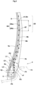
- FIG. 1 is a tire meridian cross-sectional view, including a tire rotation axis (not shown), of a pneumatic tire 1 (hereinafter, may be simply referred to as "tire 1") according to one embodiment of the present invention.
- the tire 1 of the present embodiment is suitably used for a small-sized truck, for example.
- the present invention is also applicable to the tire 1 for a passenger car or a heavy-duty vehicle, for example.
- the tire 1 in a standardized state is shown.
- the "standardized state” is a state where the tire 1 is fitted on a standardized rim R and inflated to a standardized internal pressure and no load is applied to the tire.
- the standardized state means a standard use state, corresponding to the purpose of use of the tire, where the tire is not mounted on a vehicle and no load is applied to the tire.
- dimensions and the like of components of the tire are values measured in the standardized state.
- the "standardized rim R” is a rim that is defined, in a standard system including a standard on which the tire is based, by the standard for each tire, and is, for example, the "standard rim” in the JATMA standard, the "Design Rim” in the TRA standard, or the “Measuring Rim” in the ETRTO standard.
- the "standardized internal pressure” is an air pressure that is defined, in a standard system including a standard on which the tire is based, by the standard for each tire, and is the “maximum air pressure” in the JATMA standard, the maximum value indicated in the table "TIRE LOAD LIMITS AT VARIOUS COLD INFLATION PRESSURES" in the TRA standard, or the “INFLATION PRESSURE” in the ETRTO standard.
- the tire 1 includes a tread portion 2, a pair of sidewall portions 3, and a pair of bead portions 4.
- Each sidewall portion 3 is continuous with an outer side, in a tire axial direction, of the tread portion 2, and extends in a tire radial direction.
- Each bead portion 4 is continuous with an inner side, in the tire radial direction, of the sidewall portion 3, and has a bead core 5 embedded therein.
- FIG. 2 is an enlarged view of the bead portion 4 in the right portion of FIG. 1 .
- each of the pair of bead portions 4 includes a first position P1 and a first bead thickness L1.
- the first position P1 is a position where a tire axial direction line Y1 passing through an outermost position Re, in the tire radial direction, of a rim flange Rj of the standardized rim R intersects an outer surface 4s of the bead portion 4.
- the first bead thickness L1 corresponds to the length of a perpendicular line (normal line to a tire inner cavity surface 1b) n1 drawn from the first position P1 to the tire inner cavity surface 1b.
- a portion around the first position P1 is a portion which is likely to be largely bent due to a compressive load and on which stress is likely to be concentrated, at the time of vulcanization molding.
- each of the bead portions 4 includes a third position P3 and a second bead thickness L2, for example.
- the third position P3 is a position where a tire axial direction line Y2 passing through an outermost position 5e, in the tire radial direction, of the bead core 5 intersects the outer surface 4s of the bead portion 4.
- the second bead thickness L2 corresponds to the length of the tire axial direction line Y2 drawn from the third position P3 to the tire inner cavity surface 1b.
- the tire 1 includes a carcass 6 extending between the pair of bead portions 4, and an inner liner 9 disposed inward of the carcass 6 and defining the tire inner cavity surface 1b.
- the tire 1 of the present embodiment further includes a tread rubber 2G, and a belt layer 7 located between the tread rubber 2G and the carcass 6, in the tread portion 2.
- the tread rubber 2G includes a ground-contact surface 2s which comes into contact with a road surface.
- the carcass 6 is tightened by the belt layer 7, thereby enhancing the stiffness of the tread portion 2.
- the inner liner 9 is formed of air-impermeable rubber, and serves to maintain the internal pressure.
- the tread rubber 2G, the belt layer 7, and the inner liner 9 are, for example, formed of known materials.
- the carcass 6 includes at least one carcass ply 6A.
- the carcass ply 6A includes a body portion 6a extending between the bead cores 5 of the pair of bead portions 4, and turned-up portions 6b turned up around the bead cores 5, respectively, from an inner side toward an outer side in the tire axial direction and extending in the tire radial direction.
- the carcass ply 6A including such turned-up portions 6b increases tension between the bead cores 5 and 5, thereby improving the durability of the tire 1.
- the carcass ply 6A is located on the tire inner cavity surface 1b side with respect to a midpoint C1 of the perpendicular line n1 defining the first bead thickness L1. Accordingly, the carcass ply 6A is disposed in a region where the compressive load is relatively small, and thus, stress which acts on the carcass ply 6A is reduced and occurrence of damage, breakage, or the like due to strain is inhibited, at the time of vulcanization molding.
- the carcass ply 6A is located at a second position P2 away from the first position P1 by 60% of the first bead thickness L1 on the perpendicular line n1, or is located on the tire inner cavity surface 1b side with respect to the second position P2 on the perpendicular line n1.
- the carcass ply 6A is, for example, formed by covering an array of carcass cords with topping rubber (not shown).
- topping rubber for example, organic fibers such as polyester fibers, nylon fibers, rayon fibers, polyethylene naphthalate fibers, and aramid fibers, or steel are applied, and in particular, polyester fibers are preferably applied. Occurrence of breakage or the like is likely to be caused by a compressive load rather than by a tensile load in the carcass cords, for example.
- the topping rubber is formed of a known material.
- the carcass ply 6A includes two carcass plies 6Aa, 6Ab respectively disposed on an inner side and an outer side in the tire radial direction.
- Each of the carcass plies 6Aa, 6Ab includes the body portion 6a and the turned-up portions 6b.
- Such a carcass 6 can further inhibit damage to the bead portion 4 or the like.
- each turned-up portion 6b of the inner carcass ply 6Aa is located on the tire inner cavity surface 1b side with respect to the midpoint C1 of the perpendicular line n1 defining the first bead thickness L1. Accordingly, damage or the like which occurs in the carcass ply 6A is effectively inhibited.
- An outer end 6e, in the tire radial direction, of the turned-up portion 6b is located away from a bead base line BL, by 40% or more of a tire cross-sectional height H (see FIG. 1 ), toward the outer side in the tire radial direction, for example. Accordingly, the outer end 6e is largely away from the first position P1, and thus the stiffness of the bead portion 4 is enhanced and the durability is improved.
- the outer end 6e of the turned-up portion 6b is located away from the bead base line BL toward the outer side in the tire radial direction, more preferably by 45% or more of the tire cross-sectional height H, and preferably by 80% or less of the tire cross-sectional height H and more preferably by 70% or less of the tire cross-sectional height H.
- a portion B1 around a tire maximum width position B is a region where the concentration of stress is particularly alleviated at the time of vulcanization molding.
- the outer end 6e of the turned-up portion 6b is preferably located in the portion B 1 around the tire maximum width position B.
- an outer end e1 of the inner carcass ply 6Aa and an outer end e2 of the outer carcass ply 6Ab are located away from the bead base line BL, by 40% or more of the tire cross-sectional height H, toward the outer side in the tire radial direction, and are located in the portion B 1 around the tire maximum width position B.
- the outer end e1 is an outer end, in the tire radial direction, of the turned-up portion 6b of the inner carcass ply 6Aa.
- the outer end e2 is an outer end, in the tire radial direction, of the turned-up portion 6b of the outer carcass ply 6Ab.
- the tire maximum width position B is a height position, in the tire radial direction, of the outer surface of the tire 1 for defining a tire cross-sectional width (see JATMA or the like).
- the portion B 1 around the tire maximum width position B has the tire maximum width position B at the center and extends, from the center, outward by 10% or less of the tire cross-sectional height H and inward by 10% or less of the tire cross-sectional height H in the tire radial direction.
- the tire cross-sectional height H is a distance from the bead base line BL to a tire maximum diameter position in the tire radial direction.
- the bead base line BL is a tire axial direction line passing through a rim diameter position of the standardized rim R.
- the outer end e1 of the turned-up portion 6b of the inner carcass ply 6Aa is located outward of the outer end e2 of the turned-up portion 6b of the outer carcass ply 6Ab, in the tire radial direction.
- a distance L3, in the tire radial direction, between the outer end e1 of the inner carcass ply 6Aa and the outer end e2 of the outer carcass ply 6Ab is, but is not particularly limited to, preferably not less than 5% of the tire cross-sectional height H and more preferably not less than 7% of the tire cross-sectional height H, and preferably not more than 15% of the tire cross-sectional height H and more preferably not more than 13% of the tire cross-sectional height H.
- the outer end e1 of the inner carcass ply 6Aa may be located inward of the outer end e2 of the outer carcass ply 6Ab, in the tire radial direction.
- the carcass ply 6A is located at a fourth position P4 away from the third position P3 by 30% of the second bead thickness L2, or is located on the outer surface 4s side of the bead portion 4 with respect to the fourth position P4.
- the carcass ply 6A is formed in an arc shape projecting inward in the tire axial direction in a portion near the first position P1, and thus stress can be reduced at the time of vulcanization molding.
- the turned-up portion 6b of the outer carcass ply 6Ab is located on the outer surface 4s side with respect to the fourth position P4. If the carcass ply 6A is located excessively on the outer surface 4s side, stress from the rim flange Rj greatly acts during running, thereby increasing the risk of damage or breakage.
- the tread rubber 2G is a tread rubber 2A obtained through retreading.
- the tire 1 having this tread rubber 2A is produced in a manner in which a new tread rubber 2A is adhered to a base tire (not shown) obtained by removing the tread rubber the lifespan of which has ended, and the obtained product is subjected to vulcanization molding with a mold which has a known structure, and such a tire is referred to as retreaded tire or recapped tire.
- the tread rubber 2G may be a tread rubber (not shown) obtained through retreading multiple times.
- the tread rubber 2A when the tread rubber 2A is adhered to the base tire and vulcanization molding is performed thereon, strain due to stress which acts on the carcass ply 6A is reduced, occurrence of damage, breakage, or the like is inhibited, the number of times of retreading for the tread rubber 2G can be increased, and therefore the present invention is suitable for a retreaded tire.
- FIG. 3 is an enlarged view of the bead portion 4 in the right portion of FIG. 1 .
- each bead portion 4 includes a sidewall rubber 3G, an apex rubber 8, a first reinforcing rubber 10, and a second reinforcing rubber 11.
- the first reinforcing rubber 10 is adjacent to an outer side, in the tire axial direction, of the turned-up portion 6b, for example.
- the first reinforcing rubber 10 is adjacent to the outer side, in the tire axial direction, of the turned-up portion 6b of the inner carcass ply 6Aa.
- the apex rubber 8 extends from an outer surface 5a, in the tire radial direction, of the bead core 5, outward in the tire radial direction, for example.
- the sidewall rubber 3G is disposed outward of the first reinforcing rubber 10 in the tire axial direction, for example.
- the second reinforcing rubber 11 is located between the apex rubber 8 and the body portion 6a of the carcass ply 6A, for example. In the present embodiment, the second reinforcing rubber 11 is located between the apex rubber 8 and the body portion 6a of the outer carcass ply 6Ab.
- the second reinforcing rubber 11 is located between the body portion 6a and the turned-up portion 6b of the outer carcass ply 6Ab, for example.
- the first reinforcing rubber 10 is preferably formed such that a complex elastic modulus E*1 at 70°C of the first reinforcing rubber 10 is more than a complex elastic modulus E*2 at 70°C of the sidewall rubber 3G. Accordingly, the sidewall rubber 3G having the relatively small complex elastic modulus E*2 can reduce repeated deformation when being in contact and non-contact with the ground during running, whereby stress which acts on the first position P1 can be reduced. In addition, the first reinforcing rubber 10 having the relatively large complex elastic modulus E* 1 enhances the stiffness of the bead portion 4, thereby improving durability.
- the complex elastic modulus E* 1 of the first reinforcing rubber 10 is preferably not less than 4 times the complex elastic modulus E*2 of the sidewall rubber 3G and more preferably not less than 5 times the complex elastic modulus E*2 of the sidewall rubber 3G, and preferably not more than 17 times the complex elastic modulus E*2 of the sidewall rubber 3G and more preferably not more than 8 times the complex elastic modulus E*2 of the sidewall rubber 3G.
- the complex elastic modulus E*1 at 70°C of the first reinforcing rubber 10 is preferably not less than 15 MPa and more preferably not less than 20 MPa, and preferably not more than 45 MPa and more preferably not more than 40 MPa, for example.
- the complex elastic modulus is a value measured according to the standards of JIS-K6394 under the conditions indicated below, using a dynamic viscoelasticity measuring device (EPLEXOR series) manufactured by GABO.
- the material of the second reinforcing rubber 11 is the same as that of the topping rubber of the carcass ply 6A, for example.
- a complex elastic modulus E*3 at 70°C of the second reinforcing rubber 11 is preferably less than the complex elastic modulus E*1 at 70°C of the first reinforcing rubber 10. Accordingly, the effect of inhibiting deformation can be exerted by the first reinforcing rubber 10, and the effect of absorbing strain of the turned-up portion 6b of the outer carcass ply 6Ab and strain of the turned-up portion 6b of the inner carcass ply 6Aa to improve durability can be further exerted by the second reinforcing rubber 11.
- the first reinforcing rubber 10 extends inward and outward of an outer end 8e in the tire radial direction of the apex rubber 8, in the tire radial direction, for example.
- the second reinforcing rubber 11 extends inward and outward of the outer end 8e of the apex rubber 8, in the tire radial direction, for example. Accordingly, variation in stiffness on an inner side and an outer side, in the tire radial direction, of the outer end 8e of the apex rubber 8 can be reduced, and thus deformation of the bead portion 4 can be inhibited at the time of vulcanization molding.
- An outer end 10e, in the tire radial direction, of the first reinforcing rubber 10 is located inward of the outer end 6e in the tire radial direction of the turned-up portion 6b, in the tire radial direction, for example.
- an outer end 11e, in the tire radial direction, of the second reinforcing rubber 11 is located outward of the outer end 6e in the tire radial direction of the turned-up portion 6b, in the tire radial direction, for example. Accordingly, variation in stiffness can be reduced in the bead portion 4 and the sidewall portion 3 in the tire radial direction, and thus a large reduction in durability can be inhibited.
- the outer end 10e of the first reinforcing rubber 10 is located inward of the outer end e2 of the turned-up portion 6b of the outer carcass ply 6Ab, in the tire radial direction.
- the outer end 11e of the second reinforcing rubber 11 is located outward of the outer end e1 of the turned-up portion 6b of the inner carcass ply 6Aa, in the tire radial direction.
- Such a second reinforcing rubber 11 inhibits the body portion 6a and the turned-up portion 6b from coming into contact with each other, thereby effectively inhibiting damage to the carcass ply 6A or the like at the time of vulcanization molding.
- An inner end 10i, in the tire radial direction, of the first reinforcing rubber 10, and an inner end 11i, in the tire radial direction, of the second reinforcing rubber 11 are located between the outer surface 5a of the bead core 5 and the first position P1. Accordingly, stiffness in a portion around the first position P1 can be increased, and thus the durability of the bead portion 4 can be enhanced.
- the first reinforcing rubber 10 and the second reinforcing rubber 11 are each formed as a rubber layer including no cord, for example. Such a first reinforcing rubber 10 and such a second reinforcing rubber 11 reduce occurrence of damage or the like due to contact with the carcass cords, thereby contributing to further increasing the number of times of retreading for the tread rubber G.
- a maximum thickness t1 of the first reinforcing rubber 10 is larger than a maximum thickness t2 of the second reinforcing rubber 11. Accordingly, at the time of vulcanization molding, deformation of the bead portion 4 due to compressive strain can be reduced, and thus the durability of the bead portion 4 can be improved.
- the maximum thickness t2 of the second reinforcing rubber 11 is preferably not smaller than 0.3 mm and more preferably not smaller than 0.5 mm, and preferably not larger than 2.0 mm and more preferably not larger than 1.5 mm.
- a difference (t1-t2) between the maximum thickness t1 of the first reinforcing rubber 10 and the maximum thickness t2 of the second reinforcing rubber 11 is preferably not smaller than 0.2 mm and more preferably not smaller than 0.5 mm, and preferably not larger than 3 mm and more preferably not larger than 2.5 mm.
- An overlap length La, in the tire radial direction, of the first reinforcing rubber 10 and the apex rubber 8 is, but is not particularly limited to, preferably not smaller than 9 mm and more preferably not smaller than 14 mm, and preferably not larger than 30 mm and more preferably not larger than 25 mm.
- An overlap length Lb, in the tire radial direction, of the second reinforcing rubber 11 and the apex rubber 8 is preferably not smaller than 3 mm and more preferably not smaller than 8 mm, and preferably not larger than 30 mm and more preferably not larger than 25 mm.
- the apex rubber 8 extends to the outer side in the tire radial direction with respect to the first position P1 in the present embodiment.
- the basic stiffness at the first position P1 is enhanced by such an apex rubber 8.
- the outer end 8e of the apex rubber 8 extends inward and outward of the perpendicular line n1 in the tire radial direction, for example.
- the apex rubber 8 is formed of a known material.
- a length L4, in the tire radial direction, of the apex rubber 8 is, but is not particularly limited to, preferably not less than 5% of the tire cross-sectional height H and more preferably not less than 10% of the tire cross-sectional height H, and preferably not more than 25% of the tire cross-sectional height H and more preferably not more than 20% of the tire cross-sectional height H.
- each bead portion 4 of the present embodiment includes a clinch rubber 4G adjacent to an inner side, in the tire radial direction, of the sidewall rubber 3G.
- a boundary surface K at which the sidewall rubber 3G and the clinch rubber 4G are in contact with each other, is formed in the bead portion 4.
- the clinch rubber 4G is formed of a known material.
- the boundary surface K is connected to the first position P1 in the present embodiment.
- the boundary surface K is inclined from the first position P1, outward in the tire radial direction and inward in the tire axial direction, and is connected to the first reinforcing rubber 10, for example.
- An outer end e3, in the tire radial direction, of the boundary surface K is located outward of the outer end 8e of the apex rubber 8 in the tire radial direction, for example.
- the outer end e3 of the boundary surface K is located inward of the outer end 10e of the first reinforcing rubber 10, in the tire radial direction in the present embodiment.
- Tires each having the basic structure in FIG. 1 with a size of 205/85R16LT were produced as test tires on the basis of specifications in Table 1. The durability of each test tire was tested. Specifications common to the test tires, and a testing method are as follows.
- the position "A" of the carcass ply means that the carcass ply was at a position away from the first position P1, by 50% of the first bead thickness L1, toward the tire inner cavity surface side on the perpendicular line n1.
- the position "B" of the carcass ply means that the carcass ply was at a position away from the first position P1, by 60% of the first bead thickness L1, toward the tire inner cavity surface side on the perpendicular line n1.
- the position "C" of the carcass ply means that the carcass ply was at a position away from the first position P1, by 55% of the first bead thickness L1, toward the tire inner cavity surface side on the perpendicular line n1.
- the position of the outer end 6e of the turned-up portion means a distance, in the tire radial direction, between the bead base line and the outer end e1 of the turned-up portion 6b of the inner carcass ply 6Aa / tire cross-sectional height H.
- Table 1 Comp. Ex. 1 Ex. 1 Ex. 2 Ex. 3 Ex. 4 Ex. 5 Ex. 6 Ex. 7 Ex. 8 Ex.
- the present invention includes the following aspects.
- a pneumatic tire including:
- the pneumatic tire according to Present Invention 1 in which the tread rubber is a tread rubber obtained through retreading multiple times.
- the pneumatic tire according to Present Invention 1 or 2 in which the carcass ply is located at a second position away from the first position by 60% of the first bead thickness on the perpendicular line, or is located on the tire inner cavity surface side with respect to the second position.
- each of the pair of bead portions includes an apex rubber extending from an outer surface in the tire radial direction of the bead core, outward in the tire radial direction, and a second reinforcing rubber located between the apex rubber and the body portion of the carcass ply.
Landscapes
- Engineering & Computer Science (AREA)
- Mechanical Engineering (AREA)
- Tires In General (AREA)
Applications Claiming Priority (1)
| Application Number | Priority Date | Filing Date | Title |
|---|---|---|---|
| JP2023016312A JP2024111674A (ja) | 2023-02-06 | 2023-02-06 | 空気入りタイヤ |
Publications (1)
| Publication Number | Publication Date |
|---|---|
| EP4410569A1 true EP4410569A1 (de) | 2024-08-07 |
Family
ID=89661442
Family Applications (1)
| Application Number | Title | Priority Date | Filing Date |
|---|---|---|---|
| EP24152628.4A Pending EP4410569A1 (de) | 2023-02-06 | 2024-01-18 | Luftreifen |
Country Status (2)
| Country | Link |
|---|---|
| EP (1) | EP4410569A1 (de) |
| JP (1) | JP2024111674A (de) |
Citations (4)
| Publication number | Priority date | Publication date | Assignee | Title |
|---|---|---|---|---|
| JP2002160510A (ja) * | 2000-11-27 | 2002-06-04 | Sumitomo Rubber Ind Ltd | 空気入りタイヤ |
| JP2011235783A (ja) | 2010-05-11 | 2011-11-24 | Sumitomo Rubber Ind Ltd | 更生タイヤ及びその製造方法 |
| JP2016147567A (ja) * | 2015-02-12 | 2016-08-18 | 住友ゴム工業株式会社 | タイヤ |
| EP3936352A1 (de) * | 2020-07-08 | 2022-01-12 | Sumitomo Rubber Industries, Ltd. | Luftreifen |
-
2023
- 2023-02-06 JP JP2023016312A patent/JP2024111674A/ja active Pending
-
2024
- 2024-01-18 EP EP24152628.4A patent/EP4410569A1/de active Pending
Patent Citations (4)
| Publication number | Priority date | Publication date | Assignee | Title |
|---|---|---|---|---|
| JP2002160510A (ja) * | 2000-11-27 | 2002-06-04 | Sumitomo Rubber Ind Ltd | 空気入りタイヤ |
| JP2011235783A (ja) | 2010-05-11 | 2011-11-24 | Sumitomo Rubber Ind Ltd | 更生タイヤ及びその製造方法 |
| JP2016147567A (ja) * | 2015-02-12 | 2016-08-18 | 住友ゴム工業株式会社 | タイヤ |
| EP3936352A1 (de) * | 2020-07-08 | 2022-01-12 | Sumitomo Rubber Industries, Ltd. | Luftreifen |
Also Published As
| Publication number | Publication date |
|---|---|
| JP2024111674A (ja) | 2024-08-19 |
Similar Documents
| Publication | Publication Date | Title |
|---|---|---|
| EP2628612B1 (de) | Luftreifen | |
| EP1872972B1 (de) | LKW-Luftreifen | |
| US11142027B2 (en) | Pneumatic tire | |
| US20040079460A1 (en) | Pneumatic tire | |
| CN108473004B (zh) | 充气轮胎 | |
| US11207927B2 (en) | Pneumatic tire | |
| US10486471B2 (en) | Pneumatic tire | |
| EP3213929B1 (de) | Luftreifen für passagierfahrzeuge | |
| EP3995322B1 (de) | Reifen und gürtelschicht | |
| US11254167B2 (en) | Pneumatic tyre | |
| US9656521B2 (en) | Run-flat tire | |
| EP3189979B1 (de) | Luftreifen | |
| EP0778164A1 (de) | Radialer luftreifen | |
| EP1612057A1 (de) | Luftreifen | |
| EP4410569A1 (de) | Luftreifen | |
| EP3943660B1 (de) | Reifen | |
| EP3888943A1 (de) | Luftreifen | |
| EP3936660B1 (de) | Reifen | |
| US7654295B2 (en) | Tire for motorcycle with sidewall upper layer and sidewall lower layer | |
| US20180244113A1 (en) | Run flat tire and method for manufacturing same | |
| EP1108567B1 (de) | Luftreifen | |
| EP3536522B1 (de) | Notlaufringreifen | |
| EP3366496B1 (de) | Notlaufreifen und verfahren zur herstellung davon | |
| US11358413B2 (en) | Bias tire | |
| US20220009288A1 (en) | Pneumatic tire |
Legal Events
| Date | Code | Title | Description |
|---|---|---|---|
| PUAI | Public reference made under article 153(3) epc to a published international application that has entered the european phase |
Free format text: ORIGINAL CODE: 0009012 |
|
| STAA | Information on the status of an ep patent application or granted ep patent |
Free format text: STATUS: THE APPLICATION HAS BEEN PUBLISHED |
|
| AK | Designated contracting states |
Kind code of ref document: A1 Designated state(s): AL AT BE BG CH CY CZ DE DK EE ES FI FR GB GR HR HU IE IS IT LI LT LU LV MC ME MK MT NL NO PL PT RO RS SE SI SK SM TR |