EP4410474A1 - Getaktete verstelleinheit - Google Patents
Getaktete verstelleinheit Download PDFInfo
- Publication number
- EP4410474A1 EP4410474A1 EP24000013.3A EP24000013A EP4410474A1 EP 4410474 A1 EP4410474 A1 EP 4410474A1 EP 24000013 A EP24000013 A EP 24000013A EP 4410474 A1 EP4410474 A1 EP 4410474A1
- Authority
- EP
- European Patent Office
- Prior art keywords
- unit
- lifting
- clocked
- adjustment unit
- spindle
- Prior art date
- Legal status (The legal status is an assumption and is not a legal conclusion. Google has not performed a legal analysis and makes no representation as to the accuracy of the status listed.)
- Granted
Links
Images




Classifications
-
- B—PERFORMING OPERATIONS; TRANSPORTING
- B23—MACHINE TOOLS; METAL-WORKING NOT OTHERWISE PROVIDED FOR
- B23Q—DETAILS, COMPONENTS, OR ACCESSORIES FOR MACHINE TOOLS, e.g. ARRANGEMENTS FOR COPYING OR CONTROLLING; MACHINE TOOLS IN GENERAL CHARACTERISED BY THE CONSTRUCTION OF PARTICULAR DETAILS OR COMPONENTS; COMBINATIONS OR ASSOCIATIONS OF METAL-WORKING MACHINES, NOT DIRECTED TO A PARTICULAR RESULT
- B23Q16/00—Equipment for precise positioning of tool or work into particular locations not otherwise provided for
- B23Q16/02—Indexing equipment
- B23Q16/022—Indexing equipment in which only the indexing movement is of importance
- B23Q16/026—Indexing equipment in which only the indexing movement is of importance by converting a reciprocating or oscillating movement into a rotary indexing movement
-
- B—PERFORMING OPERATIONS; TRANSPORTING
- B23—MACHINE TOOLS; METAL-WORKING NOT OTHERWISE PROVIDED FOR
- B23Q—DETAILS, COMPONENTS, OR ACCESSORIES FOR MACHINE TOOLS, e.g. ARRANGEMENTS FOR COPYING OR CONTROLLING; MACHINE TOOLS IN GENERAL CHARACTERISED BY THE CONSTRUCTION OF PARTICULAR DETAILS OR COMPONENTS; COMBINATIONS OR ASSOCIATIONS OF METAL-WORKING MACHINES, NOT DIRECTED TO A PARTICULAR RESULT
- B23Q1/00—Members which are comprised in the general build-up of a form of machine, particularly relatively large fixed members
- B23Q1/25—Movable or adjustable work or tool supports
- B23Q1/26—Movable or adjustable work or tool supports characterised by constructional features relating to the co-operation of relatively movable members; Means for preventing relative movement of such members
-
- B—PERFORMING OPERATIONS; TRANSPORTING
- B23—MACHINE TOOLS; METAL-WORKING NOT OTHERWISE PROVIDED FOR
- B23Q—DETAILS, COMPONENTS, OR ACCESSORIES FOR MACHINE TOOLS, e.g. ARRANGEMENTS FOR COPYING OR CONTROLLING; MACHINE TOOLS IN GENERAL CHARACTERISED BY THE CONSTRUCTION OF PARTICULAR DETAILS OR COMPONENTS; COMBINATIONS OR ASSOCIATIONS OF METAL-WORKING MACHINES, NOT DIRECTED TO A PARTICULAR RESULT
- B23Q1/00—Members which are comprised in the general build-up of a form of machine, particularly relatively large fixed members
- B23Q1/25—Movable or adjustable work or tool supports
- B23Q1/44—Movable or adjustable work or tool supports using particular mechanisms
- B23Q1/48—Movable or adjustable work or tool supports using particular mechanisms with sliding pairs and rotating pairs
- B23Q1/4852—Movable or adjustable work or tool supports using particular mechanisms with sliding pairs and rotating pairs a single sliding pair followed perpendicularly by a single rotating pair
-
- B—PERFORMING OPERATIONS; TRANSPORTING
- B23—MACHINE TOOLS; METAL-WORKING NOT OTHERWISE PROVIDED FOR
- B23Q—DETAILS, COMPONENTS, OR ACCESSORIES FOR MACHINE TOOLS, e.g. ARRANGEMENTS FOR COPYING OR CONTROLLING; MACHINE TOOLS IN GENERAL CHARACTERISED BY THE CONSTRUCTION OF PARTICULAR DETAILS OR COMPONENTS; COMBINATIONS OR ASSOCIATIONS OF METAL-WORKING MACHINES, NOT DIRECTED TO A PARTICULAR RESULT
- B23Q1/00—Members which are comprised in the general build-up of a form of machine, particularly relatively large fixed members
- B23Q1/25—Movable or adjustable work or tool supports
- B23Q1/44—Movable or adjustable work or tool supports using particular mechanisms
- B23Q1/48—Movable or adjustable work or tool supports using particular mechanisms with sliding pairs and rotating pairs
- B23Q1/4852—Movable or adjustable work or tool supports using particular mechanisms with sliding pairs and rotating pairs a single sliding pair followed perpendicularly by a single rotating pair
- B23Q1/4871—Movable or adjustable work or tool supports using particular mechanisms with sliding pairs and rotating pairs a single sliding pair followed perpendicularly by a single rotating pair followed parallelly by a single sliding pair
-
- B—PERFORMING OPERATIONS; TRANSPORTING
- B23—MACHINE TOOLS; METAL-WORKING NOT OTHERWISE PROVIDED FOR
- B23Q—DETAILS, COMPONENTS, OR ACCESSORIES FOR MACHINE TOOLS, e.g. ARRANGEMENTS FOR COPYING OR CONTROLLING; MACHINE TOOLS IN GENERAL CHARACTERISED BY THE CONSTRUCTION OF PARTICULAR DETAILS OR COMPONENTS; COMBINATIONS OR ASSOCIATIONS OF METAL-WORKING MACHINES, NOT DIRECTED TO A PARTICULAR RESULT
- B23Q16/00—Equipment for precise positioning of tool or work into particular locations not otherwise provided for
- B23Q16/02—Indexing equipment
- B23Q16/022—Indexing equipment in which only the indexing movement is of importance
- B23Q16/024—Indexing equipment in which only the indexing movement is of importance and by converting a continuous movement into a linear indexing movement
-
- B—PERFORMING OPERATIONS; TRANSPORTING
- B23—MACHINE TOOLS; METAL-WORKING NOT OTHERWISE PROVIDED FOR
- B23Q—DETAILS, COMPONENTS, OR ACCESSORIES FOR MACHINE TOOLS, e.g. ARRANGEMENTS FOR COPYING OR CONTROLLING; MACHINE TOOLS IN GENERAL CHARACTERISED BY THE CONSTRUCTION OF PARTICULAR DETAILS OR COMPONENTS; COMBINATIONS OR ASSOCIATIONS OF METAL-WORKING MACHINES, NOT DIRECTED TO A PARTICULAR RESULT
- B23Q16/00—Equipment for precise positioning of tool or work into particular locations not otherwise provided for
- B23Q16/02—Indexing equipment
- B23Q16/08—Indexing equipment having means for clamping the relatively movable parts together in the indexed position
- B23Q16/083—Indexing equipment having means for clamping the relatively movable parts together in the indexed position with a reciprocating or oscillating drive
Definitions
- the invention relates to a clocked adjustment unit with two linear thrust units.
- the compensation device has a cylinder-piston unit and limits the swivel angle of the welding guns.
- leveling plates, leveling wedges, etc. are generally used.
- the individual workpiece is aligned manually using these leveling pieces.
- the present invention is based on the problem of simplifying the alignment of the height level of a workpiece.
- each of the linear thrust units has an actuating pawl.
- a rotatably mounted spindle nut that controls a lifting spindle can be driven by means of each of the actuating pawls.
- Each of the linear thrust units is assigned exactly one of two lifting directions of the lifting spindle.
- the cycled adjustment unit has two drive units, each of which has a linear thrust unit with an actuating pawl.
- a spindle nut is pivoted or rotated by a design-specified angle using the actuating pawl. This step can be repeated several times.
- the spindle nut drives a lifting spindle using a screw gear.
- the lifting spindle is moved in its axial direction.
- One of the linear thrust units is used to raise the lifting spindle in cycles.
- the other linear thrust unit is used to lower the lifting spindle in cycles.
- FIGS. 1 - 16 show a clocked adjustment unit (10) in the form of a pneumatically clocked adjustment unit (10).
- Such adjustment units (10) are used, for example, to align the height of workpieces for subsequent automated joining operations. For example, body panels can be aligned despite existing tolerances so that they can then be joined using an automated welding gun.
- the adjustment unit (10) shown in the figures has a housing group (20) and a relatively adjustable Lifting spindle (141).
- the lifting spindle (141) is part of a lifting spindle group (140).
- the linearly oriented stroke of the lifting spindle group (140) relative to the housing group (20) is 6 millimeters in the exemplary embodiment.
- the lifting spindle (141) is extended in a first stroke direction (145) relative to the housing group (20).
- the lifting spindle (141) is retracted in a second stroke direction (146).
- a stroke of 10 millimeters is also conceivable.
- a stroke monitoring group (170) is arranged on the housing group (20).
- the Figure 2 shows a longitudinal section of the adjustment unit (10) along its vertical central longitudinal plane.
- the Figure 5 shows a longitudinal section of a housing base body (22) of the housing group (20) with the same cutting plane.
- a section through the drive units (60, 90) parallel to this cutting plane is shown.
- the Figure 4 shows a longitudinal section of the housing through the drive units (60, 90), wherein the cutting plane is normal to the cutting planes of the Figures 2 , 3 , and 5 lies.
- the housing group (20) has a housing (21) as a supporting component.
- the housing (21) forms the stationary part of two pneumatic drive units (60, 90) that interact with a two-stage gear (120).
- the housing base body (22), cf. the Figures 2 - 5 has a longitudinal bore (23), a beam holder (24), two guide holders (25), a spindle drive holder (26) and media lines (27).
- the beam holder (24) and the guide holders (25) are designed symmetrically to the vertical central longitudinal plane of the housing group (20).
- the beam holder (24) is, for example, cuboid-shaped.
- the guide mounts (25) open into the beam mount (24).
- the two guide mounts (25) are arranged symmetrically to a vertical central transverse plane of the housing group (20).
- the guide mounts (25) each have a cylindrical bearing mount (28) and a seal mount (29) adjacent to the top of the housing group (20).
- the spindle drive holder (26) is arranged centrally between the guide holders (25). It is designed in several stages. It has a cover part holder (31), a spindle nut holder (32) and a spindle locking holder (33).
- the cover part holder (31) is at least approximately cuboid-shaped.
- the cover part (52) is fastened in the cover part holder (31) by means of, for example, two cover part fastening screws (53).
- the cover part (52) On its upper side, has a shaft sealing ring (54) which prevents dirt from penetrating the interior (35) of the housing group (20).
- sliding disks (not shown here) are inserted.
- the spindle nut holder (32) is limited in the vertical direction by means of the cover part (52) and a spindle nut system (34).
- the spindle nut system (34) is a flat surface that is perpendicular to the height direction (16) of the adjustment unit. (10). It is also conceivable to insert sliding disks into the housing base body (22). These are then designed, for example, like the sliding disks of the cover part (52). Another design for the bearing of the spindle nut (131) is also conceivable.
- the spindle nut receptacle (32) In the radial direction, the spindle nut receptacle (32) is limited by a largely cylindrical housing wall (36).
- the spindle nut receptacle (32) is connected to the longitudinal bore (23) in an engagement recess (37).
- the engagement recess (37) covers a sector of 100 degrees. The central axis of the sector coincides with the central axis of the spindle drive receptacle (26).
- the spindle locking receptacle (33) is a cylindrical bore that connects the spindle nut receptacle (32) with the beam receptacle (24).
- Two stroke return spring receptacles (38) are formed on the underside of the housing base body (22). These are cylindrical recesses into which a stroke return spring (55) is inserted when the adjustment unit (10) is mounted.
- the longitudinal bore (23) penetrates the housing base body (22) in the longitudinal direction (15).
- the longitudinal bore (23) is sealed at both ends by means of closure plugs (56).
- closure plugs (56) Between the closure plugs (56) the longitudinal bore (23) has a constant cross-sectional area.
- the engagement recess (37) divides the longitudinal bore (23) into a first section (39) and a second section (41), each of which borders on one of the closure plugs (56).
- a first media channel (44) guided in the housing base body ('22) consists of a first longitudinal channel (45) adjacent to the first media connection (42) and a first transverse channel (46).
- the first media channel (44) opens into the first section (39) of the longitudinal bore (23) immediately next to the associated sealing plug (56).
- the second media channel (47) is connected to the second media connection (43). This also has a longitudinal channel (48) and a transverse channel (49). The second media channel (47) opens into the second section (41) of the longitudinal channel (23) directly next to the associated sealing plug (56).
- the two pneumatic drive units (60, 90) each have a tappet unit (62; 92) guided in the longitudinal bore (23).
- the tappet units (62, 92) of this embodiment are piston units (62, 92).
- the two piston units (62, 92) are constructed, for example, from identical components.
- a first piston unit (62) is seated in the first section (39) of the longitudinal bore (23) so as to be longitudinally displaceable.
- the second piston unit (92) is arranged in the second section (41) of the longitudinal bore (23) so as to be displaceable in the longitudinal direction (15).
- the individual piston unit (62; 92) forms, together with the longitudinal bore (23) of the housing base body (22), a linear thrust unit (61; 91) in the form of a cylinder-piston unit (61; 91). It is also conceivable, for example, to insert a cylinder-piston unit consisting of a cylinder and the piston unit (62; 92) into the housing base body (22).
- the Figures 6 and 7 show a piston unit (62; 92) in two isometric views.
- the individual piston unit (62; 92) has a tappet body (63; 93) in the form of a piston body (63; 93), an actuating pawl (71; 101) and two e.g. common tappet return springs (64; 94).
- the piston body (63; 93) has a piston seal (65). This is designed as a double seal.
- the piston seal (65) rests against the wall of the longitudinal bore (23).
- the individual piston body (63; 93) separates a pressure chamber (66; 96) arranged between the closure plug (56) and the piston body (63; 93) from the environment (1) in the longitudinal bore (23).
- a guide groove (67) is stamped into the piston body (63; 93). This is oriented in the longitudinal direction (15) of the adjustment unit (10).
- a guide pin (57) attached to the housing base body (22) engages in the guide groove (67).
- the guide pin (57) and the guide groove (67) limit the stroke of the respective piston unit (62; 92) of the cylinder-piston unit (61; 91).
- the stroke of the individual piston unit (62; 92) relative to the housing (21) is 10 millimeters.
- An actuating pawl (71; 101) is pivotably mounted in the piston body (63; 93).
- a pivot pin (68) which penetrates the piston body (63; 93) and the actuating pawl (71; 101) serves for the mounting.
- the actuating pawl (71; 101) is additionally loaded into a thrust position (73; 103) relative to the piston body (63; 93) by means of two pawl springs (72).
- the piston body (63; 93) On the end face facing away from the piston seal (65), the piston body (63; 93) has two spring recesses (69). Each of the spring recesses (69) accommodates a tappet return spring (64; 94) which is supported on the piston body (93; 93) of the other piston unit (92; 62).
- the tappet return springs (64, 94) are also referred to below as piston return springs (64, 94).
- the two piston return springs (64, 94) are designed as compression springs. Buckling of the piston return springs (64, 94) is prevented by means of a guide pin (97) in each case.
- an actuating pawl (71; 101) is shown.
- the actuating pawl (71; 101) is designed symmetrically to its vertical central longitudinal plane. It has a through hole (74) for receiving the pivot pin (68).
- a pivot stop (75) in the form of a shoulder is formed on each of the side surfaces.
- the front side of the actuating pawl (71; 101) facing away from the through hole (74) is referred to below as the thrust flank (76; 106).
- the thrust flank (76; 106) is designed as a flat surface in the embodiment shown.
- a receiving recess (77) is formed on the top of the actuating pawl (71; 101).
- the receiving recess (77) is delimited by a holding flank (78), a contact flank (79) and a return flank (81; 111). These merge into one another.
- the return flank (81; 111) is designed, for example, as a flat surface.
- the return flank (81; 111) and the thrust flank (76; 106) delimit a rounded pawl curve (82; 112).
- the return flank (81; 111) and the thrust flank (76; 106) enclose an angle of 60 degrees. The apex of this angle lies outside the pawl curve (82; 112).
- the Figure 9 shows a spindle nut (131).
- the spindle nut (131) has a cylindrical envelope contour in the embodiment and a central internal thread (132).
- the internal thread (132) has a nominal diameter of 12 millimeters.
- the internal thread (132) is designed as a fine thread with a pitch of one millimeter. A pitch of 0.5 millimeters is also conceivable. The pitch is the distance between the starting point and the end point of a turn of the helix.
- the pitch of the internal thread (132) is, for example, at least 1/48 and a maximum of 3/24 of the nominal diameter of the internal thread (132).
- the spindle nut (131) has a nut body (133) with a circumferential annular groove (134).
- the annular groove (134) has straight flanks in the example.
- ten identical driving pins (135, 136) are located on a common pitch circle (137), cf. Figure 13 .
- the diameter (d TK ) of the pitch circle (137) is 20 millimeters in the exemplary embodiment.
- the diameter of the individual driving pin (135; 136) is one tenth of this diameter in the exemplary embodiment.
- the minimum stroke (h min ) of each of the cylinder-piston units (61; 91) is greater than the product of the pitch circle diameter (dTK) of the driving pins (135, 136) and the sine of the quotient of the circle number ( ⁇ ) and the number of driving pins (135, 136).
- the stroke of each of the cylinder-piston units (61; 91) is 1.62 times the minimum value.
- the cylinder-piston unit (61; 91) with the actuating pawl (71; 101) and the spindle nut (131) forms a first gear stage (121) of the transmission (120).
- a linear movement of the respective piston unit (62; 92) is converted into a rotary movement of the spindle nut (131).
- the spindle nut (131) is screwed with its internal thread (132) onto an external thread (142) of the lifting spindle (141).
- the screw gear of the spindle nut (131) and the lifting spindle (141) forms a second gear stage (122) of the gear (120).
- Above the external thread (142), the lifting spindle (141) has a sealing collar (147).
- the shaft sealing ring (54) of the cover part (52) rests against this.
- the lifting spindle group (140) with the lifting spindle (141) is mounted in the housing group (20) in a rotationally secure manner and is guided linearly in the height direction (16).
- the Figure 10 shows the lifting spindle group (140).
- the lifting spindle (141) is located between an upper lifting beam (151) and a lower guide beam (166).
- a lifting spindle screw (143) rests with its screw head (144) on the guide beam (166), penetrates the lifting spindle (141) and is fastened in the lifting beam (151), cf. Figure 2 .
- the guide bar (166) is seated in the bar holder (24) of the housing base body (22) so that it can be moved in the vertical direction (16).
- the two stroke return springs (55) are supported in spring recesses (167) of the guide bar (166).
- Two guide columns (161) are arranged symmetrically to the vertical central transverse plane of the housing group (20).
- the guide columns (161) are rigidly connected to the lifting beam (151) and to the guide beam (166) by means of a fastening screw (162) each.
- the individual guide column (161) has a constant circular cross-section in the vertical direction (16). For example, the outer surfaces (163) of the guide columns (161) are polished.
- the guide columns (161) are each guided in a slide bearing sleeve (58) so that they can move in the stroke directions (145, 146).
- the respective slide bearing sleeve (58) is located in the housing base body (22).
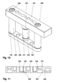
- the lifting beam (151), cf. Figure 11 is cuboid-shaped. On its upper side (152) it has several fastening threads (153) and centering pin receptacles (154). For example, contour stones that are adapted to the contour of the body panels to be accommodated can be attached to these.
- the length of the lifting beam (151) oriented in the longitudinal direction (15) corresponds to the sum of the length of the housing group (20) and the stroke monitoring group (170) in this longitudinal direction (15).
- a fastening thread (155) for the lifting spindle screw (143) and two screw seating surfaces (156) for the fastening screws (162) are arranged.
- the sleeve holder (157) is, for example, a cylindrical two-stage recess.
- the Figure 12 shows the stroke monitoring group (170) with the protective cover (182) of a protective housing (181) removed.
- the stroke monitoring group (170) has a position sensor (171).
- this is designed as a stroke-dependent, linear potentiometer. Its electrical resistance is between one kiloohm and 150 kiloohms with a stroke of 12.5 millimeters.
- the output signal of the position sensor (171) depends on its current stroke.
- the output signal can map the stroke, for example, proportionally, progressively, degressively, etc.
- the position sensor (171) has a base body (172) and an extendable sleeve (173).
- the sleeve (173) is loaded into an extended end position by a spring.
- the head (174) of the sleeve (173) is hemispherical.
- the adjustment unit (10) is mounted, the head (174) of the sleeve (173) lies in the sleeve holder (157) of the lifting beam (151).
- the stroke of the position sensor (171) therefore corresponds to the stroke of the lifting spindle (141).
- the base body (172) of the position sensor (171) and a part of the sleeve (173) are arranged in the protective housing (181).
- An electrical conversion unit (183) is arranged in the protective housing (181).
- the electrical conversion unit (183) is used to convert the output signal of the position sensor (171) into a data protocol that can be processed by the higher-level control system.
- the transmission to the higher-level control system takes place via a unidirectional or bidirectional asymmetric interface, for example.
- the data protocol is designed as a LAN, IO-Link ® , etc.
- the interface can be designed as a parallel or serial interface, for example.
- the data and signal lines (184) are used to transfer the data and signal signals.
- the processed actual data of the position sensor (171) are transmitted to the higher-level control via a point-to-point connection.
- the hub monitoring group (170) can then take place, for example, in a frequency range of 2.4 gigahertz or 5.8 gigahertz.
- the data protocol can be designed, for example, as UART, Bluetooth, WLAN, IO-Link ® wireless, etc.
- the stroke monitoring group (170) can have a computing and evaluation unit.
- the pneumatic control of the adjustment unit (10) can be integrated into the stroke monitoring group (170). This can be set up as a control loop together with the stroke monitoring group (170).
- the adjustment unit (10) is started. As soon as the setpoint value is reached, the stroke value or the reaching of the setpoint value is transmitted to the higher-level control system.
- the stroke monitoring group (170) can have a program storage unit.
- the individual stored sequence programs contain, for example, the intended stroke of the lifting spindle (141), the intended current stroke acceleration and stroke speed, etc.
- one of the adjustment sequence programs is called up by the higher-level control system, for example.
- the sequence program is started.
- a confirmation signal is transmitted to the higher-level control system.
- This can be a binary signal, for example.
- the bidirectional signal transmission can also be wired or wireless.
- a supply line (192) leads from a pressure source (191) to a pre-valve (193).
- This is, for example, a 3/3-way valve (193) with a zero-lock position.
- the individual switching positions can be switched electromagnetically, for example.
- the pre-valve (193) can be spring-loaded and reset to the zero-lock position. From the zero-lock position, the pre-valve (193) can alternatively be switched either to a first operating position for the first cylinder-piston unit (61) or to a second operating position for the second cylinder-piston unit (91).
- a first operating valve (194) is connected downstream of the pre-valve (193).
- the first operating valve (194) is an electromagnetically operated 3/2-way valve with spring return.
- the operating valve (194) has a pressure position and the emptying position (195) shown in Figure 13.
- a silencer (196) that discharges into the environment (1) is connected downstream of the operating valve (194).
- the first operating valve (194) is hydraulically connected to the pressure chamber (66) of the first cylinder-piston unit (61). As soon as the pre-valve (193) is switched to the first operating position and the operating valve (194) is switched to the pressure position, the pressure chamber (66) of the first cylinder-piston unit (61) is pressurized with pneumatic pressure from the pressure source (191). When the operating valve (194) is switched to the emptying position (195), the piston return springs (64, 94) move the piston unit (62) relative to the cylinder of the cylinder-piston unit (61). The pressure chamber (66) is compressed and discharged via the silencer (196). emptied. The individual cylinder-piston unit (61; 91) is thus designed to be single-acting.
- a second operating valve (201) is connected downstream of the pre-valve (193).
- the second operating valve (201) is constructed in the same way as the first operating valve (194).
- the pressure chamber (96) of the second cylinder-piston unit (91) is loaded.
- the pressure chamber (96) of the single-acting second cylinder-piston unit (91) is emptied via the second silencer (202).
- the Figures 14 - 16 show sections of the housing group (20) during a drive cycle.
- the first piston unit (62) is released from the Figure 4 shown initial position (211) into the Figure 14
- the contact position (212) shown is shifted.
- the first pressure chamber (66) is enlarged.
- the actuating pawl (71) rests with its thrust flank (76) on a first driving pin (135) of the spindle nut (131).
- the piston return springs (64, 94) are compressed.
- the second cylinder-piston unit (91) remains at rest.
- the first piston unit (62) is removed from the representation of the Figure 14 further to the right against the force of the piston return springs (64, 94).
- the first actuating pawl (71) moves the first driving pin (135) until the piston unit (62) reaches the Figure 15
- the piston end position (213) shown is reached.
- the driving pin (135) resting on the actuating pawl (71) is now rotated by one pitch.
- the spindle nut (131) has been rotated in such a way that that the lifting spindle (141) is moved further out of the housing group (20).
- the lifting spindle group (140) is thereby raised.
- the current supply to the solenoid coil (197) of the first operating valve (194) is switched off.
- the spindle nut (131) is not rotated any further.
- the first operating valve (194) switches to the emptying position (195) by means of the valve spring (198).
- This switching can be time-controlled.
- a limit or proximity switch on or in the housing base body (22), for example, which triggers a switching of the respective operating valve (194; 201) when the piston end position (213) is reached.
- the valve control can be provided in the stroke monitoring group (170). It is also conceivable to use the position of the lifting beam (151) determined in the piston end position (213) by means of the stroke monitoring (170) for reversing the operating valve (194; 201).
- the pneumatic pressure in the pressure chamber (66) of the first cylinder-piston unit (61) is reduced.
- the piston return springs (64, 94) push the first piston unit (62) in the direction of the Figure 4 shown initial position (211).
- the spindle nut (131) and the lifting spindle (141) are stationary.
- a second driving pin (136) of the spindle nut (131) contacts the non-return flank (81) of the actuating pawl (71), cf. Figure 16 .
- the actuating pawl (71) is pivoted around the pivot pin (68). This puts a load on the pawl springs (72).
- the actuating pawl (71) slides with the return flank (81) and the pawl rounding (82) along the second driving pin (136). As soon as the actuating pawl (71) has left the second driving pin (136), the actuating pawl (71) is returned to its thrust position (76) by means of the relaxing pawl springs (72). The spindle nut (131) and the lifting spindle (141) are not moved during the return stroke of the first piston unit (62). For example, the first piston unit (62) is moved to the position shown in the Figure 4 shown initial position (211).
- the next cycle can now be carried out, either time-controlled or based on a release signal from a second limit switch or proximity switch, in which the spindle nut (131) is rotated by a further partial step using the second driving pin (136).
- the lifting spindle (141) is raised further accordingly.
- the intended stroke of the lifting spindle (141) is reached when the stroke monitoring (170) outputs a corresponding signal.
- the stroke to be achieved for the signal output can be adjustable.
- the first cylinder-piston unit (61) In order to lower the lifting spindle (141), the first cylinder-piston unit (61) remains in the starting position (211).
- the second cylinder-piston unit (91) is controlled by means of the pre-valve (193) and the second operating valve (201).
- the lifting movement of the second piston unit (92) rotates the spindle nut (131) in the representations of the Figures 14 - 16 anti-clockwise.
- the lifting spindle (141) is lowered.
- the stroke monitoring can be carried out as described in connection with the operation of the first cylinder-piston unit (61).
- the Figures 17 and 18 show another variant of a clocked adjustment unit (310).
- the cutting plane of the Figure 18 corresponds to the cutting plane of the Figure 4 of the first embodiment.
- the drive units (360, 390) each have an electromagnet unit (361; 391) as a linear thrust unit (361; 391).
- the individual electromagnet unit (361; 391) can be connected to a power source by means of two electrical lines (365).
- Each of the electromagnet units (361; 391) can be switched on individually, e.g. by means of a pulse-controlled, self-resetting button, repeatedly for a time interval.
- Each of the electromagnet units (361; 391) has a cylinder pot (366; 396) and a tappet unit (362; 392).
- the cylinder pot (366; 396) has an electrical coil in its wall (367) that is connected to the electrical lines (365).
- the cylinder pot (366; 396) is screwed into the housing (21) from the outside. Its opening (368) points into the housing (21).
- the individual tappet unit (362; 392) has a tappet body (363; 393) in which the associated actuating pawl (71; 101) is pivotably mounted.
- the actuating pawl (71; 101) and its mounting are designed as described in connection with the first embodiment.
- a guide body (372) is mounted on the tappet body (363; 393) by means of a connecting pin (371).
- the guide body (371) is cylindrical. It is mounted in the cylinder pot (366; 396) so that it can move in the longitudinal direction (15).
- the guide body (372) is made of a soft iron material.
- two plunger return springs (364, 394) are also arranged between the two plunger bodies (363, 393). These are designed and arranged in the same way as the tappet return springs (64, 94) described in connection with the first embodiment.
- the gear (120) and the lifting spindle group (140) and all other components are, for example, largely designed as described in connection with the first embodiment.
- the Figures 17 and 18 The clocked adjustment unit (310) shown is designed without a stroke monitoring group (170). However, it is also conceivable to design the electromagnetically clocked adjustment unit (310) with a stroke monitoring group (170). This is then designed, for example, as described in connection with the first embodiment.
- the first drive unit (360) is energized several times in succession for a short time interval each time.
- the electrical coil builds up a magnetic field.
- the guide body (372) and with it the entire plunger unit (362) are moved to the right in the illustration in Figure 18.
- the actuating pawl (71) turns the spindle nut (131) by one increment clockwise.
- the lifting spindle (141) raises the lifting beam (151).
- the individual drive unit (360) with the linear thrust unit (361), the spindle nut (131) and the lifting spindle (141) is also designed to be single-acting in this embodiment.
- the plunger unit (362) is reset by means of the piston return springs (364, 394). The next time the electrical coil is energized, the next cycle is carried out.
- the lowering of the lifting beam (151) is carried out by means of the actuation of the second drive unit (390).
Landscapes
- Engineering & Computer Science (AREA)
- Mechanical Engineering (AREA)
- Transmission Devices (AREA)
- Actuator (AREA)
Abstract
Description
- Die Erfindung betrifft eine getaktete Verstelleinheit mit zwei Linear-Schubeinheiten.
- Aus der
DE 100 63 191 A1 ist eine Ausgleichsvorrichtung für Roboterschweißzangen bekannt. Die Ausgleichsvorrichtung hat eine Zylinder-Kolbeneinheit und begrenzt den Aufschwenkwinkel der Schweißzangen. - Um das Höhenniveau von Werkstücken auszugleichen oder anzupassen, werden im Allgemeinen Ausgleichsbleche, Ausgleichskeile, etc. eingesetzt. Das einzelne Werkstück wird manuell mittels dieser Ausgleichstücke ausgerichtet.
- Der vorliegenden Erfindung liegt die Problemstellung zugrunde, das Ausrichten des Höhenniveaus eines Werkstücks zu vereinfachen.
- Diese Problemstellung wird mit den Merkmalen des Hauptanspruches gelöst. Dazu weist jede der Linear-Schubeinheiten jeweils eine Betätigungsklinke auf. Eine drehbar gelagerte, eine Hubspindel steuernde Spindelmutter ist mittels jeder der Betätigungsklinken antreibbar. Jeder einzelnen der Linear-Schubeinheiten ist jeweils genau eine von zwei Hubrichtungen der Hubspindel zugeordnet.
- Die getaktete Verstelleinheit hat zwei Antriebseinheiten, die jeweils eine Linear-Schubeinheit mit einer Betätigungsklinke aufweisen. Mittels der Betätigungsklinke wird eine Spindelmutter um einen konstruktiv vorgegebenen Winkel geschwenkt oder gedreht. Dieser Schritt kann mehrfach wiederholt erfolgen. Die Spindelmutter treibt mittels eines Schraubgetriebes eine Hubspindel an. Die Hubspindel wird dabei in ihrer axialen Richtung bewegt. Eine der Linear-Schubeinheiten wird eingesetzt, um die Hubspindel taktweise anzuheben. Die andere Linear-Schubeinheit wird eingesetzt, um die Hubspindel getaktet abzusenken.
- Weitere Einzelheiten der Erfindung ergeben sich aus den Unteransprüchen und der nachfolgenden Beschreibung schematisch dargestellter Ausführungsformen.
- Figur 1:
- Pneumatisch getaktete Verstelleinheit;
- Figur 2:
- Längsschnitt der Verstelleinheit aus
Figur 1 ; - Figur 3:
- Schnitt der Verstelleinheit durch die Pneumatikkanäle;
- Figur 4:
- Schnitt des Antriebs der Verstelleinheit;
- Figur 5:
- Längsschnitt des Gehäusegrundkörpers;
- Figur 6:
- Kolbeneinheit mit Betätigungsklinke;
- Figur 7:
- Unteransicht von
Figur 6 ; - Figur 8:
- Betätigungsklinke;
- Figur 9:
- Spindelmutter;
- Figur 10
- Hubspindelgruppe;
- Figur 11:
- Hubbalken;
- Figur 12:
- Hubüberwachung;
- Figur 13:
- Pneumatikschaltplan;
- Figur 14:
- Gehäusegruppe bei Beginn des Förderns;
- Figur 15:
- Gehäusegruppe bei ausgefahrener Zylinder-Kolbeneinheit;
- Figur 16:
- Rückhub der Zylinder-Kolben-Einheit;
- Figur 17:
- Elektromagnetisch getaktete Verstelleinheit;
- Figur 18:
- Schnitt des Antriebs von
Figur 17 . - Die
Figuren 1 - 16 zeigen eine getaktete Verstelleinheit (10) in der Bauform einer pneumatisch getakteten Verstelleinheit (10). Derartige Verstelleinheiten (10) werden beispielsweise zum Ausrichten der Höhenlage von Werkstücken für nachfolgende automatisierte Fügebearbeitungen eingesetzt. So können z.B. Karosseriebleche trotz vorhandener Toleranzen so ausgerichtet werden, dass sie anschließend mittels einer automatisierten Schweißzange gefügt werden können. - Die in den Figuren dargestellte Verstelleinheit (10) hat eine Gehäusegruppe (20) und eine relativ hierzu verstellbare Hubspindel (141). Im Ausführungsbeispiel ist die Hubspindel (141) Teil einer Hubspindelgruppe (140). Der linear orientierte Hub der Hubspindelgruppe (140) relativ zur Gehäusegruppe (20) beträgt im Ausführungsbeispiel 6 Millimeter. Die Hubspindel (141) wird hierbei in einer ersten Hubrichtung (145) gegenüber der Gehäusegruppe (20) ausgefahren. In einer zweiten Hubrichtung (146) wird die Hubspindel (141) eingefahren. Auch ein Hub von 10 Millimeter ist denkbar. An der Gehäusegruppe (20) ist beispielsweise eine Hubüberwachungsgruppe (170) angeordnet.
- Die
Figur 2 zeigt einen Längsschnitt der Verstelleinheit (10) entlang ihrer vertikalen Mittenlängsebene. DieFigur 5 zeigt mit derselben Schnittebene einen Längsschnitt eines Gehäusegrundkörpers (22) der Gehäusegruppe (20). In derFigur 3 ist ein zu dieser Schnittebene paralleler Schnitt durch die Antriebseinheiten (60, 90) dargestellt. DieFigur 4 zeigt einen Längsschnitt des Gehäuses durch die Antriebseinheiten (60, 90), wobei die Schnittebene normal zu den Schnittebenen derFiguren 2 ,3 , und5 liegt. - Die Gehäusegruppe (20) hat als tragendes Bauteil ein Gehäuse (21). Das Gehäuse (21) bildet in diesem Ausführungsbeispiel den ortsfesten Teil von zwei pneumatische Antriebseinheiten (60, 90), die mit einem zweistufigen Getriebe (120) zusammenwirken.
- Das Gehäuse (21), vgl. die
Figuren 1 - 4 , ist zumindest annähernd quaderförmig ausgebildet. Es weist den Gehäusegrundkörper (22) auf, der mittels eines Bodenteils (51) und eines Deckelteils (52) verschlossen ist. Der Gehäusegrundkörper (22), vgl. dieFiguren 2 - 5 hat eine Längsbohrung (23), eine Balkenaufnahme (24), zwei Führungsaufnahmen (25), eine Spindeltriebaufnahme (26) und Medienleitungen (27). - Die Balkenaufnahme (24) und die Führungsaufnahmen (25) sind symmetrisch zur vertikalen Mittenlängsebene der Gehäusegruppe (20) ausgebildet. Die Balkenaufnahme (24) ist beispielsweise quaderförmig ausgebildet. Bei montierter Verstelleinheit (10) ist sie mittels des Bodenteils (51) verschlossen.
- In die Balkenaufnahme (24) münden die Führungsaufnahmen (25). Die beiden Führungsaufnahmen (25) sind symmetrisch zu einer vertikalen Mittelquerebene der Gehäusegruppe (20) angeordnet. Die Führungsaufnahmen (25) haben jeweils eine zylindrisch ausgebildete Lageraufnahme (28) und eine an die Oberseite der Gehäusegruppe (20) angrenzende Dichtungsaufnahme (29).
- Die Spindeltriebaufnahme (26) ist mittig zwischen den Führungsaufnahmen (25) angeordnet. Sie ist mehrstufig ausgebildet. Sie hat eine Deckelteilaufnahme (31), eine Spindelmutteraufnahme (32) und eine Spindelsicherungsaufnahme (33). Die Deckelteilaufnahme (31) ist zumindest annährend quaderförmig ausgebildet. In der montierten Verstelleinheit (10) ist in der Deckelteilaufnahme (31) das Deckelteil (52) mittels z.B. zwei Deckelteil-Befestigungsschrauben (53) befestigt. An seiner Oberseite trägt das Deckelteil (52) einen Wellendichtring (54), der das Eindringen von Verschmutzungen in den Innenraum (35) der Gehäusegruppe (20) verhindert. In der Unterseite des Deckelteils (52) sind beispielsweise hier nicht dargestellte Gleitscheiben eingesetzt.
- Die Spindelmutteraufnahme (32) wird in vertikaler Richtung mittels des Deckelteils (52) und einer Spindelmutteranlage (34) begrenzt. Die Spindelmutteranlage (34) ist eine ebene Fläche, die normal zur Höhenrichtung (16) der Verstelleinheit (10) angeordnet ist. Es ist auch denkbar, in den Gehäusegrundkörper (22) Gleitscheiben einzusetzen. Diese sind dann beispielsweise so ausgebildet wie die Gleitscheiben des Deckelteils (52). Auch eine andere Ausbildung der Lagerung der Spindelmutter (131) ist denkbar.
- In radialer Richtung ist die Spindelmutteraufnahme (32) mittels einer weitgehend zylindrisch ausgebildeten Gehäusewandung (36) begrenzt. In einer Eingriffsausnehmung (37) ist die Spindelmutteraufnahme (32) mit der Längsbohrung (23) verbunden. Im Ausführungsbeispiel überstreicht die Eingriffsausnehmung (37) einen Sektor von 100 Grad. Die Mittelachse des Sektors fällt mit der Mittelachse der Spindeltriebaufnahme (26) zusammen.
- Die Spindelsicherungsaufnahme (33) verbindet als zylindrische Bohrung die Spindelmutteraufnahme (32) mit der Balkenaufnahme (24). An der Unterseite des Gehäusegrundkörpers (22) sind zwei Hub-Rückstellfederaufnahmen (38) ausgebildet. Dies sind zylinderförmige Einsenkungen, in die bei montierter Verstelleinheit (10) jeweils eine Hub-Rückstellfeder (55) eingesetzt ist.
- Die Längsbohrung (23) durchdringt den Gehäusegrundkörper (22) in der Längsrichtung (15). Bei zusammengebauter Verstelleinheit (10) ist die Längsbohrung (23) an ihren beiden Enden mittels Verschlussstopfen (56) abgedichtet verschlossen. Zwischen den Verschlussstopfen (56) hat die Längsbohrung (23) eine z.B. konstante Querschnittsfläche. Die Eingriffsausnehmung (37) unterteilt die Längsbohrung (23) in einen ersten Abschnitt (39) und in einen zweiten Abschnitt (41), die jeweils an einen der Verschlussstopfen (56) angrenzen.
- An der der Hubüberwachungsgruppe (170) abgewandten Stirnseite des Gehäusegrundkörpers (22) sind zwei Medienanschlüsse (42, 43) angeordnet. Ein erster, im Gehäusegrundkörper ('22) geführter Medienkanal (44) besteht aus einem ersten, an den ersten Medienschluss (42) angrenzenden Längskanal (45) und einem ersten Querkanal (46). Der erste Medienkanal (44) mündet in den ersten Abschnitt (39) der Längsbohrung (23) unmittelbar neben dem zugehörigen Verschlussstopfen (56).
- An den zweiten Medienanschluss (43) schließt der zweite Medienkanal (47) an. Auch dieser hat einen Längskanal (48) und einen Querkanal (49). Der zweite Medienkanal (47) mündet in den zweiten Abschnitt (41) des Längskanals (23) unmittelbar neben dem zugehörigen Verschlussstopfen (56).
- Die beiden pneumatischen Antriebseinheiten (60, 90) haben jeweils eine in der Längsbohrung (23) geführte Stößeleinheit (62; 92). Die Stößeleinheiten (62, 92) dieses Ausführungsbeispiels sind Kolbeneinheit (62, 92). Die beiden Kolben-einheiten (62, 92) sind beispielsweise aus zueinander identischen Bauteilen aufgebaut. Eine erste Kolbeneinheit (62) sitzt längsverschieblich im ersten Abschnitt (39) der Längsbohrung (23). Die zweite Kolbeneinheit (92) ist in der Längsrichtung (15) verschiebbar im zweiten Abschnitt (41) der Längsbohrung (23) angeordnet. Die einzelne Kolbeneinheit (62; 92) bildet zusammen mit der Längsbohrung (23) des Gehäusegrundkörpers (22) eine Linear-Schubeinheit (61; 91) in der Bauform einer Zylinder-Kolben-Einheit (61; 91). Es ist auch denkbar, z.B. jeweils eine aus einem Zylinder und der Kolbeneinheit (62; 92) bestehende Zylinder-Kolben-Einheit in den Gehäusegrundkörper (22) einzusetzen.
- Die
Figuren 6 und 7 zeigen eine Kolbeneinheit (62; 92) in zwei isometrischen Ansichten. Die einzelne Kolbeneinheit (62; 92) hat einen Stößelkörper (63; 93) in der Bauform eines Kolbenkörpers (63; 93), eine Betätigungsklinke (71; 101) und zwei z.B. gemeinsame Stößelrückstellfedern (64; 94). Der Kolbenkörper (63; 93) trägt eine Kolbendichtung (65). Diese ist als Doppeldichtung ausgelegt. Bei zusammengebauter Verstelleinheit (10) liegt die Kolbendichtung (65) an der Wandung der Längsbohrung (23) an. Der einzelne Kolbenkörper (63; 93) grenzt in der Längsbohrung (23) einen zwischen dem Verschlussstopfen (56) und den Kolbenkörper (63; 93) angeordneten Druckraum (66; 96) von der Umgebung (1) ab. - Im Kolbenkörper (63; 93) ist eine Führungsnut (67) eingeprägt. Diese ist in der Längsrichtung (15) der Verstelleinheit (10) orientiert. Bei montierter Verstelleinheit (10) greift ein am Gehäusegrundkörper (22) befestigter Führungsstift (57) in die Führungsnut (67) ein. Der Führungsstift (57) und die Führungsnut (67) begrenzen den Hub der jeweiligen Kolbeneinheit (62; 92) der Zylinder-Kolben-Einheit (61; 91). Im Ausführungsbeispiel beträgt der Hub der einzelnen Kolbeneinheit (62; 92) relativ zum Gehäuse (21) 10 Millimeter.
- Im Kolbenkörper (63; 93) ist eine Betätigungsklinke (71; 101) schwenkbar gelagert. Zur Lagerung dient ein Schwenkstift (68), der den Kolbenkörper (63; 93) und die Betätigungsklinke (71; 101) durchdringt. Die Betätigungsklinke (71; 101) wird zusätzlich mittels zwei Klinkenfedern (72) relativ zum Kolbenkörper (63; 93) in eine Schubstellung (73; 103) belastet.
- An der der Kolbendichtung (65) abgewandten Stirnseite hat der Kolbenkörper (63; 93) zwei Federeinsenkungen (69). Jede der Federeinsenkungen (69) nimmt eine Stößelrückstellfeder (64; 94) auf, die sich am Kolbenkörper (93; 93) der jeweiligen anderen Kolbeneinheit (92; 62) abstützt. Die Stößelrückstellfedern (64, 94) sind im Folgenden auch als Kolbenrückstellfedern (64, 94) bezeichnet. Die beiden Kolbenrückstellfedern (64, 94) sind als Druckfedern ausgebildet. Ein Knicken der Kolbenrückstellfedern (64, 94) wird mittels jeweils eines Führungsstifts (97) verhindert. Bei unbelastetem Druckraum (66; 96) wird die zugehörige Kolbeneinheit (62; 92) in Richtung des jeweiligen Verschlussstopfens (56) belastet.
- In der
Figur 8 ist eine Betätigungsklinke (71; 101) dargestellt. Die Betätigungsklinke (71; 101) ist symmetrisch zu ihrer vertikalen Mittenlängsebene ausgebildet. Sie hat eine Durchgangsbohrung (74) zur Aufnahme des Schwenkstifts (68). An den Seitenflächen ist jeweils ein Schwenkanschlag (75) in Form eines Absatzes ausgebildet. Die der Durchgangsbohrung (74) abgewandte Stirnseite der Betätigungsklinke (71; 101) ist im Folgenden als Schubflanke (76; 106) bezeichnet. Die Schubflanke (76; 106) ist im dargestellten Ausführungsbeispiel als ebene Fläche ausgebildet. - An der Oberseite der Betätigungsklinke (71; 101) ist eine Aufnahmesenke (77) ausgebildet. Die Aufnahmesenke (77) wird von einer Halteflanke (78), einer Anlageflanke (79) und einer Rückschlagflanke (81; 111) begrenzt. Diese gehen ineinander über. Die Rückschlagflanke (81; 111) ist beispielsweise als ebene Fläche ausgebildet. Die Rückschlagflanke (81; 111) und die Schubflanke (76; 106) begrenzen eine abgerundete Klinkenrundung (82; 112). Im Ausführungsbeispiel schließen die Rückschlagflanke (81; 111) und die Schubflanke (76; 106) einen Winkel von 60 Grad ein. Die Scheitellinie dieses Winkels liegt außerhalb der Klinkenrundung (82; 112).
- Die
Figur 9 zeigt eine Spindelmutter (131). Die Spindelmutter (131) hat im Ausführungsbeispiel eine zylindrische Hüllkontur und ein zentrales Innengewinde (132). Im Ausführungsbeispiel hat das Innengewinde (132) einen Nenndurchmesser von 12 Millimeter. Beispielsweise ist das Innengewinde (132) als Feingewinde mit einer Steigung von einem Millimeter ausgebildet. Auch eine Steigung von 0,5 Millimetern ist denkbar. Die Steigung ist die Entfernung zwischen dem Anfangspunkt und dem Endpunkt einer Windung der Schraubenlinie. Die Steigung des Innengewindes (132) beträgt z.B. mindestens 1/48 und maximal 3/24 des Nenndurchmessers des Innengewindes (132). - Die Spindelmutter (131) hat einen Mutterkörper (133) mit einer umlaufenden Ringnut (134). Die Ringnut (134) hat im Ausführungsbeispiel gerade Flanken. In der Ringnut (134) sitzen z.B. zehn identische Mitnahmestifte (135, 136) auf einem gemeinsamen Teilkreis (137), vgl.
Figur 13 . Der Durchmesser (dTK) des Teilkreises (137) beträgt im Ausführungsbeispiel 20 Millimeter. Der Durchmesser des einzelnen Mitnahmestifts (135; 136) beträgt im Ausführungsbeispiel ein Zehntel dieses Durchmessers. - Für den Mindesthub (hmin) jeder der Zylinder-Kolben-Einheiten (61; 91) gilt:

- dTK:
- Teilkreisdurchmesser der Mitnahmestifte
- n:
- Kreiszahl
- n:
- Anzahl der Mitnahmestifte
- Der Mindesthub (hmin) jeder der Zylinder-Kolben-Einheiten (61; 91) ist größer als das Produkt aus dem Teilkreisdurchmessers (dTK) der Mitnahmestifte (135, 136) und dem Sinus aus dem Quotienten der Kreiszahl (π) und der Anzahl der Mitnahmestifte (135, 136). Im Ausführungsbeispiel beträgt der Hub jeder der Zylinder-Kolben-Einheiten (61; 91) das 1,62-fach des Mindestwerts.
- In der jeweiligen Antriebseinheit (60; 90) bildet die Zylinder-Kolben-Einheit (61; 91) mit der Betätigungsklinke (71; 101) und der Spindelmutter (131) eine erste Getriebestufe (121) des Getriebes (120). Mittels dieser ersten Getriebestufe (121) wird eine lineare Bewegung der jeweiligen Kolbeneinheit (62; 92) in eine rotatorische Bewegung der Spindelmutter (131) umgewandelt.
- Die Spindelmutter (131) ist mit ihrem Innengewinde (132) auf ein Außengewinde (142) der Hubspindel (141) aufgeschraubt. Das Schraubgetriebe der Spindelmutter (131) und der Hubspindel (141) bildet eine zweite Getriebestufe (122) des Getriebes (120). Oberhalb des Außengewindes (142) hat die Hubspindel (141) einen Dichtbund (147). An diesem liegt der Wellendichtring (54) des Deckelteils (52) an. Die Hubspindelgruppe (140) mit der Hubspindel (141) ist verdrehsicher in der Gehäusegruppe (20) gelagert und in der Höhenrichtung (16) linear geführt.
- Die
Figur 10 zeigt die Hubspindelgruppe (140). Die Hubspindel (141) sitzt zwischen einem obenliegenden Hubbalken (151) und einem untenliegenden Führungsbalken (166). Eine Hubspindelschraube (143) liegt mit ihrem Schraubenkopf (144) am Führungsbalken (166) an, durchdringt die Hubspindel (141) und ist im Hubbalken (151) befestigt, vgl.Figur 2 . Der Führungsbalken (166) sitzt in der Höhenrichtung (16) verschiebbar in der Balkenaufnahme (24) des Gehäusegrundkörpers (22). Die beiden Hub-Rückstellfedern (55) stützten sich in Federausnehmungen (167) des Führungsbalkens (166) ab. - Symmetrisch zur vertikalen Mittenquerebene der Gehäusegruppe (20) sind zwei Führungssäulen (161) angeordnet. Die Führungssäulen (161) sind mittels jeweils einer Befestigungsschraube (162) starr mit dem Hubbalken (151) und mit dem Führungsbalken (166) verbunden. Die einzelne Führungssäule (161) hat in der Höhenrichtung (16) einen konstanten kreisförmigen Querschnitt. Beispielsweise sind die Mantelflächen (163) der Führungssäulen (161) poliert ausgeführt.
- In der zusammengebauten Verstelleinheit (10) sind die Führungssäulen (161) jeweils in den Hubrichtungen (145, 146) verschiebbar in jeweils einer Gleitlagerhülse (58) geführt. Die jeweilige Gleitlagerhülse (58) sitzt im Gehäusegrundkörper (22).
- Der Hubbalken (151), vgl.
Figur 11 , ist quaderförmig ausgebildet. An seiner Oberseite (152) hat er mehrere Befestigungsgewinde (153) und Zentrierstiftaufnahmen (154). An diesen können beispielsweise Kontursteine befestigt werden, die an die Kontur der aufzunehmenden Karosseriebleche angepasst sind. - Die in der Längsrichtung (15) orientierte Länge des Hubbalkens (151) entspricht im Ausführungsbeispiel der Summe der Länge der Gehäusegruppe (20) und der Hubüberwachungsgruppe (170) in dieser Längsrichtung (15). Im Hubbalken (151), vgl.
Figur 11 , sind ein Befestigungsgewinde (155) für die Hubspindelschraube (143) sowie zwei Schraubensitzflächen (156) für die Befestigungsschrauben (162) angeordnet. Im äußeren Bereich des Hubbalkens (151) hat dieser eine nach unten offene Pinolenaufnahme (157). Die Pinolenaufnahme (157) ist beispielsweise eine zylinderförmige zweistufige Ausnehmung. In der unteren Ausnehmungsstufe (158) sitzt bei montierter Verstelleinheit (10) ein Wellendichtring (159). - Die
Figur 12 zeigt die Hubüberwachungsgruppe (170) bei abgenommenen Schutzdeckel (182) eines Schutzgehäuses (181). Die Hubüberwachungsgruppe (170) hat einen Positionssensor (171). Dieser ist im Ausführungsbeispiel als hubabhängiger, linearer Potentiometer ausgebildet. Sein elektrischer Widerstand beträgt zwischen einem Kiloohm und 150 Kiloohm bei einem Hub von 12,5 Millimetern. Das Ausgangssignal des Positionssensors (171) ist abhängig von seinem momentanen Hub. Das Ausgangssignal kann den Hub der z.B. proportional, progressiv, degressiv, etc. abbilden. - Der Positionssensor (171) hat einen Grundkörper (172) und eine ausfahrbare Pinole (173). Die Pinole (173) ist mittels einer Feder in eine ausgefahrene Endlage belastet. Der Kopf (174) der Pinole (173) ist halbkugelförmig ausgebildet. Bei montierter Verstelleinheit (10) liegt der Kopf (174) der Pinole (173) in der Pinolenaufnahme (157) des Hubbalkens (151). Der Hub des Positionssensors (171) entspricht damit dem Hub der Hubspindel (141).
- Der Grundkörper (172) des Positionssensors (171) und ein Teil der Pinole (173) sind im Schutzgehäuse (181) angeordnet. In dem Schutzgehäuse (181) ist eine elektrische Umwandlungseinheit (183) angeordnet. Mittels der elektrischen Umwandlungseinheit (183) wird z.B. das Ausgangssignal des Positionssensors (171) in ein von der übergeordneten Steuerung verarbeitbares Datenprotokoll umgewandelt. Die Übertragung zur übergeordneten Steuerung erfolgt z.B. über eine unidirektionale oder bidirektionale asymmetrische Schnittstelle. Das Datenprotokoll ist im Ausführungsbeispiel z.B. als LAN, IO-Link®, etc. ausgebildet. Die Schnittstelle kann beispielsweise als parallele oder serielle Schnittstelle ausgebildet sein. Mittels einer Daten- und Signalleitung (184) werden die so aufbereiteten Ist-Daten des Positionssensors (171) mittels einer Punkt-zu-Punkt-Verbindung an die übergeordnete Steuerung übertragen.
- Es ist auch denkbar, eine drahtlose Schnittstelle zwischen der Hubüberwachungsgruppe (170) und der übergeordneten Steuerung auszubilden. Die Übertragung kann dann beispielsweise in einem Frequenzbereich von 2,4 Gigahertz oder 5,8 Gigahertz erfolgen. In diesem Fall kann das Datenprotokoll z.B. als UART, Bluetooth, WLAN, IO-Link® wireless, etc. ausgebildet sein.
- Die Hubüberwachungsgruppe (170) kann eine Rechen- und Auswerteeinheit aufweisen. Beispielsweise kann die pneumatische Ansteuerung der Verstelleinheit (10) in die Hubüberwachungsgruppe (170) integriert sein. Diese kann zusammen mit der Hubüberwachungsgruppe (170) als Regelkreis aufgebaut sein. Nach Vorgabe eines Sollwerts für den Hub wird die Verstelleinheit (10) gestartet. Sobald der Sollwert erreicht ist, wird der Hubwert oder das Erreichen des Sollwerts an die übergeordnete Steuerung übermittelt.
- Die Hubüberwachungsgruppe (170) kann eine Programmspeichereinheit aufweisen. In den einzelnen gespeicherten Ablaufprogrammen ist beispielsweise der vorgesehene Hub der Hubspindel (141), die vorgesehene momentane Hubbeschleunigung und Hubgeschwindigkeit, etc. hinterlegt. Beim Betrieb wird beispielsweise von der übergeordneten Steuerung eines der Verstell-Ablaufprogramme aufgerufen. Nach der Übermittlung des z.B. binären Startsignals wird das Ablaufprogramm gestartet. Sobald der Sollwert erreicht ist, wird ein Bestätigungssignal an die übergeordnete Steuerung übermittelt. Dies kann z.B. ein binäres Signal sein. Die bidirektionale Signalübertragung kann auch in diesem Fall leitungsgebunden oder drahtlos erfolgen.
- In der
Figur 13 ist ein vereinfachter pneumatischer Schaltplan der Ansteuerung der pneumatisch getakteten Verstelleinheit (10) dargestellt. Von einer Druckquelle (191) aus führt eine Versorgungsleitung (192) zu einem Vorventil (193). Dieses ist beispielsweise ein 3/3 Wegeventil (193) mit Sperr-Nullstellung. Die einzelnen Schaltstellungen sind beispielsweise elektromagnetisch schaltbar. Gegebenenfalls kann das Vorventil (193) federbelastet in die Sperr-Nullstellung zurückgestellt werden. Von der Sperr-Nullstellung aus ist das Vorventil (193) alternativ entweder in eine erste Betriebsstellung für die erste Zylinder-Kolben-Einheit (61) oder in eine zweite Betriebsstellung für die zweite Zylinder-Kolben-Einheit (91) schaltbar. - In der ersten Betriebsstellung ist dem Vorventil (193) ein erstes Betriebsventil (194) nachgeschaltet. Das erste Betriebsventil (194) ist im Ausführungsbeispiel ein elektromagnetisch betätigtes 3/2-Wegeventil mit Federrückstellung. Das Betriebsventil (194) hat eine Druckstellung und die in der Figur 13 dargestellte Entleerungsstellung (195). In der Entleerungsstellung (195) ist dem Betriebsventil (194) ein in die Umgebung (1) ableitender Schalldämpfer (196) nachgeschaltet.
- Das erste Betriebsventil (194) ist mit dem Druckraum (66) der ersten Zylinder-Kolben-Einheit (61) hydraulisch verbunden. Sobald das Vorventil (193) in die erste Betriebsstellung geschaltet ist und das Betriebsventil (194) in die Druckstellung geschaltet ist, wird der Druckraum (66) der ersten Zylinder-Kolben-Einheit (61) mit pneumatischem Druck aus der Druck-, quelle (191) beaufschlagt. Beim Umschalten des Betriebsventils (194) in die Entleerungsstellung (195) verschieben die Kolben-Rückstellfedern (64, 94) die Kolbeneinheit (62) relativ zum Zylinder der Zylinder-Kolben-Einheit (61). Der Druckraum (66) wird komprimiert und über den Schalldämpfer (196) entleert. Die einzelne Zylinder-Kolben-Einheit (61; 91) ist damit einfachwirkend ausgebildet.
- In der zweiten Betriebsstellung ist dem Vorventil (193) ein zweites Betriebsventil (201) nachgeschaltet. Das zweite Betriebsventil (201) ist im Ausführungsbeispiel so aufgebaut wie das erste Betriebsventil (194). In seiner Druckstellung wird der Druckraum (96) der zweiten Zylinder-Kolben-Einheit (91) belastet. In der dargestellten Entleerungsposition wird der Druckraum (96) der einfach wirkenden zweiten Zylinder-Kolben-Einheit (91) über den zweiten Schalldämpfer (202) entleert.
- Die
Figuren 14 - 16 zeigen Schnitte der Gehäusegruppe (20) bei einem Antriebstakt. Sobald beispielsweise die erste Zylinder-Kolben-Einheit (61) mit pneumatischen Druck beaufschlagt wird, wird die erste Kolbeneinheit (62) aus der in derFigur 4 dargestellten Ausgangslage (211) in die in derFigur 14 dargestellte Kontaktlage (212) verschoben. Der erste Druckraum (66) wird vergrößert. Die Betätigungsklinke (71) legt sich mit ihrer Schubflanke (76) an einen ersten Mitnahmestift (135) der Spindelmutter (131) an. Die Kolbenrückstellfedern (64, 94) werden komprimiert. Die zweite Zylinder-Kolben-Einheit (91) verbleibt in Ruhe. - Beim Fortsetzen der Druckbeaufschlagung wird die erste Kolbeneinheit (62) aus der Darstellung der
Figur 14 weiter gegen die Kraft der Kolbenrückstellfedern (64, 94) nach rechts verschoben. Die erste Betätigungsklinke (71) verschiebt hierbei den ersten Mitnahmestift (135), bis die Kolbeneinheit (62) die in derFigur 15 dargestellte Kolbenendlage (213) erreicht. Der an der Betätigungsklinke (71) anliegende Mitnahmestift (135) ist jetzt beispielsweise um eine Teilung weitergedreht. Die Spindelmutter (131) wurde hierbei beispielsweise derart gedreht, dass die Hubspindel (141) weiter aus der Gehäusegruppe (20) herausgefahren wird. Hierbei wird die Hubspindelgruppe (140) angehoben. - Sobald die Kolbeneinheit (62) die in der
Figur 15 dargestellte Kolbenendlage (213) erreicht hat, wird die Bestromung der Magnetspule (197) des ersten Betriebsventils (194) abgeschaltet. Die Spindelmutter (131) wird nicht weiter gedreht. Das erste Betriebsventil (194) schaltet mittels der Ventilfeder (198) in die Entleerungsstellung (195). Dieses Umschalten kann zeitgesteuert erfolgen. Es ist aber auch denkbar, am oder im Gehäusegrundkörper (22) z.B. einen End- oder Näherungsschalter anzuordnen, der bei Erreichen der Kolbenendlage (213) ein Umschalten des jeweiligen Betriebsventils (194; 201) auslöst. Bei in oder unmittelbar an der Verstelleinheit (10) angeordneten Betriebsventilen (194, 201) kann die Ventilsteuerung in der Hubüberwachungsgruppe (170) vorgesehen sein. Auch ist es denkbar, die in der Kolbenendlage (213) mittels der Hubüberwachung (170) ermittelte Position des Hubbalkens (151) für die Umsteuerung des Betriebsventils (194; 201) einzusetzen. - Nach dem Umschalten des Betriebsventils (194) in die Entleerungsstellung (195) wird der pneumatische Druck im Druckraum (66) der ersten Zylinder-Kolben-Einheit (61) vermindert. Die Kolbenrückstellfedern (64, 94) schieben die erste Kolbeneinheit (62) in Richtung der in der
Figur 4 dargestellten Ausgangslage (211) . Die Spindelmutter (131) und die Hubspindel (141) stehen still. Ein zweiter Mitnahmezapfen (136) der Spindelmutter (131) kontaktiert die Rückschlagflanke (81) der Betätigungsklinke (71), vgl.Figur 16 . Beim weiteren Einfahren der Kolbeneinheit (62) wird die Betätigungsklinke (71) um den Schwenkstift (68) geschwenkt. Hierbei werden die Klinkenfedern (72) belastet. Die Betätigungsklinke (71) gleitet mit der Rückschlagflanke (81) und der Klinkenrundung (82) entlang des zweiten Mitnahmezapfens (136). Sobald die Betätigungsklinke (71) den zweiten Mitnahmezapfen (136) verlassen hat, wird die Betätigungsklinke (71) mittels der sich entspannenden Klinkenfedern (72) in ihre Schublage (76) zurückgestellt. Die Spindelmutter (131) und die Hubspindel (141) werden während des Rückhubs der ersten Kolbeneinheit (62) nicht bewegt. Beispielsweise wird die erste Kolbeneinheit (62) in die in derFigur 4 dargestellte Ausgangslage (211) zurückbewegt. - Zeitgesteuert oder aufgrund eines Freigabesignals eines zweiten End- oder Näherungsschalters kann nun der nächste Takt erfolgen, bei dem mittels des zweiten Mitnahmezapfens (136) die Spindelmutter (131) um einen weiteren Teilschritt gedreht wird. Die Hubspindel (141) wird entsprechend weiter angehoben.
- Der vorgesehene Hub der Hubspindel (141) ist erreicht, wenn die Hubüberwachung (170) ein entsprechendes Signal ausgibt. Der für die Signalausgabe zu erreichende Hub kann einstellbar sein.
- Um die Hubspindel (141) abzusenken, verbleibt die erste Zylinder-Kolben-Einheit (61) in der Ausgangslage (211). Mittels des Vorventils (193) und des zweiten Betriebsventils (201) wird die zweite Zylinder-Kolben-Einheit (91) angesteuert. Die Hubbewegung der zweiten Kolbeneinheit (92) dreht die Spindelmutter (131) in den Darstellungen der
Figuren 14 - 16 entgegen dem Uhrzeigersinn. Die Hubspindel (141) wird abgesenkt. Die Hubüberwachung kann so erfolgen, wie im Zusammenhang mit der Betätigung der ersten Zylinder-Kolben-Einheit (61) beschrieben. - Die
Figuren 17 und 18 zeigen eine weitere Variante einer getakteten Verstelleinheit (310). Die Schnittebene derFigur 18 entspricht der Schnittebene derFigur 4 des ersten Ausführungsbeispiels. Die Antriebseinheiten (360, 390) weisen in dieser Variante als Linear-Schubeinheit (361; 391) jeweils eine Elektromagneteinheit (361; 391) auf. Die einzelne Elektromagneteinheit (361; 391) ist mittels zweier elektrischer Leitungen (365) an eine Stromquelle anschließbar. Jede der Elektromagneteinheiten (361; 391) ist einzeln z.B. mittels eines impulsgesteuerten, selbstrückstellenden Tasters wiederholt für jeweils ein Zeitintervall einschaltbar. - Jede der Elektromagneteinheiten (361; 391) hat einen Zylindertopf (366; 396) und eine Stößeleinheit (362; 392). Der Zylindertopf (366; 396) hat in seiner Wandung (367) eine elektrische Spule, die an die elektrischen Leitungen (365) angeschlossen ist. Im dargestellten Ausführungsbeispiel ist der Zylindertopf (366; 396) jeweils von außen in das Gehäuse (21) eingeschraubt. Seine Öffnung (368) zeigt in das Gehäuse (21).
- Die einzelne Stößeleinheit (362; 392) hat einen Stößelkörper (363; 393), in dem die zugeordnete Betätigungsklinke (71; 101) jeweils schwenkbar gelagert ist. Die Betätigungsklinke (71; 101) und ihre Lagerung sind so ausgebildet, wie im Zusammenhang mit dem ersten Ausführungsbeispiel beschreiben. Am Stößelkörper (363; 393) ist jeweils mittels eines Verbindungsstiftes (371) ein Führungskörper (372) gelagert. Der Führungskörper (371) ist zylindrisch ausgebildet. Er ist im Zylindertopf (366; 396) in der Längsrichtung (15) verschiebbar gelagert. Beispielsweise besteht der Führungskörper (372) aus einem Weicheisenmaterial.
- Zwischen den beiden Stößelkörpern (363, 393) sind auch in diesem Ausführungsbeispiel zwei Stößelrückstellfedern (364, 394) angeordnet. Diese sind so ausgebildet und angeordnet wie die im Zusammenhang mit dem ersten Ausführungsbeispiel beschriebenen Stößelrückstellfedern (64, 94).
- Das Getriebe (120) und die Hubspindelgruppe (140) und sämtliche sonstigen Bauteile sind beispielsweise weitgehend so ausgebildet, wie im Zusammenhang mit dem ersten Ausführungsbeispiel beschrieben.
- Die in diesen
Figuren 17 und 18 dargestellte getaktete Verstelleinheit (310) ist ohne Hubüberwachungsgruppe (170) ausgebildet. Es ist aber denkbar, auch die elektromagnetisch getaktete Verstelleinheit (310) mit einer Hubüberwachungsgruppe (170) auszubilden. Diese ist dann beispielsweise so ausgebildet, wie im Zusammenhang mit dem ersten Ausführungsbeispiel beschrieben. - Zum Anheben des Hubbalkens (151) wird beispielsweise die erste Antriebseinheit (360) mehrmals hintereinander für jeweils ein kurzes Zeitintervall bestromt. Die elektrische Spule baut ein Magnetfeld auf. Der Führungskörper (372) und mit ihm die gesamte Stößeleinheit (362) werden in der Darstellung der Figur 18 nach rechts verschoben. Die Betätigungsklinke (71) dreht die Spindelmutter (131) um ein Inkrement im Uhrzeigersinn. Die Hubspindel (141) hebt den Hubbalken (151) an. Die einzelne Antriebseinheit (360) mit der Linear-Schubeinheit (361), der Spindelmutter (131) und der Hubspindel (141) ist auch in diesem Ausführungsbeispiel einfachwirkend ausgebildet. Nach dem Abschalten der Bestromung der elektrischen Spule wird die Stößeleinheit (362) mittels der Kolbenrückstellfedern (364, 394) zurückgestellt. Bei der nächsten Bestromung der elektrischen Spule wird der nächste Takt ausgeführt.
- Das Absenken des Hubbalkens (151) erfolgt mittels der Betätigung der zweiten Antriebseinheit (390).
- Auch Kombinationen der einzelnen Ausführungsbeispiele sind denkbar.
-
- 1
- Umgebung
- 10
- Verstelleinheit, pneumatisch getaktet
- 15
- Längsrichtung
- 16
- Höhenrichtung
- 20
- Gehäusegruppe
- 21
- Gehäuse
- 22
- Gehäusegrundkörper
- 23
- Längsbohrung
- 24
- Balkenaufnahme
- 25
- Führungsaufnahmen
- 26
- Spindeltriebaufnahme
- 27
- Medienleitungen
- 28
- Lageraufnahme
- 29
- Dichtungsaufnahme
- 31
- Deckelteilaufnahme
- 32
- Spindelmutteraufnahme
- 33
- Spindelsicherungsaufnahme
- 34
- Spindelmutteranlage
- 35
- Innenraum von (20)
- 36
- Gehäusewandung
- 37
- Eingriffsausnehmung
- 38
- Hub-Rückstellfederaufnahmen
- 39
- erster Abschnitt von (23)
- 41
- zweiter Abschnitt von (23)
- 42
- Medienanschluss
- 43
- Medienanschluss, zweiter Medienanschluss
- 44
- Medienkanal, erster Medienkanal
- 45
- Längskanal
- 46
- Querkanal
- 47
- Medienkanal, zweiter Medienkanal
- 48
- Längskanal
- 49
- Querkanal
- 51
- Bodenteil
- 52
- Deckelteil
- 53
- Deckelteil-Befestigungsschrauben
- 54
- Wellendichtring
- 55
- Hub-Rückstellfeder
- 56
- Verschlussstopfen
- 57
- Führungsstift
- 58
- Gleitlagerhülse
- 60
- Antriebseinheit, erste Antriebseinheit
- 61
- Linear-Schubeinheit, Zylinder-Kolben-Einheit, erste Zylinder-Kolben-Einheit
- 62
- Stößeleinheit, Kolbeneinheit, erste Kolbeneinheit
- 63
- Stößelkörper, Kolbenkörper
- 64
- Stößelrückstellfeder, Kolbenrückstellfeder
- 65
- Kolbendichtung
- 66
- Druckraum
- 67
- Führungsnut
- 68
- Schwenkstift
- 69
- Federeinsenkungen
- 71
- Betätigungsklinke
- 72
- Klinkenfedern
- 73
- Schubstellung
- 74
- Durchgangsbohrung
- 75
- Schwenkanschlag
- 76
- Schubflanke
- 77
- Aufnahmesenke
- 78
- Halteflanke
- 79
- Anlageflanke
- 81 -
- Rückschlagflanke
- 82
- Klinkenrundung
- 90
- Antriebseinheit, zweite Antriebseinheit
- 91
- Linear-Schubeinheit, Zylinder-Kolben-Einheit, zweite Zylinder-Kolben-Einheit
- 92
- Stößeleinheit, Kolbeneinheit, zweite Kolbeneinheit
- 93
- Stößelkörper, Kolbenkörper
- 94
- Stößelrückstellfeder, Kolbenrückstellfeder
- 96
- Druckraum
- 97
- Führungsstift
- 101.
- Betätigungsklinke
- 103
- Schubstellung
- 106
- Schubflanke
- 111
- Rückschlagflanke
- 112
- Klinkenrundung
- 120
- Getriebe
- 121
- erste Getriebestufe
- 131
- Spindelmutter
- 132
- Innengewinde
- 133
- Mutterkörper
- 134
- Ringnut
- 135
- Mitnahmestifte, erster Mitnahmestift
- 136
- Mitnahmestifte, zweiter Mitnahmestift
- 137
- Teilkreis
- 140
- Hubspindelgruppe
- 141
- Hubspindel
- 142
- Außengewinde
- 143
- Hubspindelschraube
- 144
- Schraubenkopf
- 145
- Hubrichtung anheben
- 146
- Hubrichtung absenken
- 147
- Dichtbund
- 151
- Hubbalken
- 152
- Oberseite
- 153
- Befestigungsgewinde
- 154
- Zentrierstiftaufnahmen
- 155
- Befestigungsgewinde
- 156
- Schraubensitzflächen
- 157
- Pinolenaufnahme
- 158
- Ausnehmungsstufe
- 159
- Wellendichtring
- 161
- Führungssäulen
- 162
- Befestigungsschraube
- 163
- Mantelflächen
- 166
- Führungsbalken
- 167
- Federausnehmungen
- 170
- Hubüberwachungsgruppe
- 171
- Positionssensor
- 172
- Grundkörper
- 173
- Pinole
- 174
- Kopf von (173)
- 181
- Schutzgehäuse
- 182
- Schutzdeckel
- 183
- elektrische Umwandlungseinheit
- 184
- Daten- und Signalleitung
- 191
- Druckquelle
- 192
- Versorgungsleitung
- 193
- Vorventil, 3/3-Wegeventil
- 194
- Betriebsventil, erstes Betriebsventil, 3/2-Wegeventil
- 195
- Entleerungsstellung
- 196
- Schalldämpfer
- 197
- Magnetspule
- 198
- Ventilfeder
- 201
- Betriebsventil, zweites Betriebsventil
- 202
- Schalldämpfer
- 211
- Ausgangslage
- 212
- Kontaktlage
- 213
- Kolbenendlage
- 310
- Verstelleinheit, elektromagnetisch getaktet
- 360
- Antriebseinheit, erste Antriebseinheit
- 361
- Linear-Schubeinheit, Elektromagneteinheit
- 362
- Stößeleinheit
- 363
- Stößelkörper
- 364
- Stößelrückstellfedern
- 365
- elektrische Leitungen
- 366
- Zylindertopf
- 367
- Wandung
- 368
- Öffnung
- 371
- Verbindungsstift
- 372
- Führungskörper
- 390
- Antriebseinheit
- 391 .
- Linear-Schubeinheit, Elektromagneteinheit
- 392
- Stößeleinheit
- 393
- Stößelkörper
- 394
- Stößelrückstellfedern
- 396
- Zylindertopf
- dTK
- Durchmesser des Teilkreises [mm]
- hmin
- Mindesthub von (61; 91) [mm]
- n
- Kreiszahl
- n
- Anzahl von (135, 136)
Claims (10)
- Getaktete Verstelleinheit (10, 310) mit zwei Linear-Schubeinheiten (61, 91; 361, 391),wobei jede der Linear-Schubeinheiten (61; 91; 361; 391) jeweils eine Betätigungsklinke (71; 101) aufweist,wobei eine drehbar gelagerte, eine Hubspindel (141) steuernde Spindelmutter (131) mittels jeder der Betätigungsklinken (71; 101) antreibbar ist undwobei jeder einzelnen der Linear-Schubeinheiten (61; 91; 361; 391) jeweils genau eine von zwei Hubrichtungen (145; 146) der Hubspindel (141) zugeordnet ist.
- Getaktete Verstelleinheit (10) nach Anspruch 1, dadurch gekennzeichnet, dass die einzelne Linear-Schubeinheit (61; 91; 361; 391) eine Stößeleinheit (62; 92; 362; 392) mit einer darin schwenkbar gelagerten Betätigungsklinke (71; 101) hat.
- Getaktete Verstelleinheit (10) nach Anspruch 2, dadurch gekennzeichnet, dass die Stößeleinheiten (62, 92; 362, 392) und die Spindelmutter (131) in einem gemeinsamen Gehäuse (21) angeordnet sind, aus dem die Hubspindel (141) herausragt.
- Getaktete Verstelleinheit (10) nach Anspruch 3, dadurch gekennzeichnet, dass die Hubspindel (141) Teil einer Hubspindelgruppe (140) ist, die einen Hubbalken (151) aufweist und die in zwei im Gehäuse (21) mittels Gleitlagerhülsen (58) gelagerten Führungssäulen (161) geführt ist.
- Getaktete Verstelleinheit (10) nach Anspruch 4, dadurch gekennzeichnet, dass der Hubbalken (151) in die absenkende Hubrichtung (146) gegenüber dem Gehäuse (21) mittels zweier Hub-Rückstellfedern (55) federbelastet ist.
- Getaktete Verstelleinheit (10) nach Anspruch 1, dadurch gekennzeichnet, dass jede der Linear-Schubeinheiten (61; 91; 361; 391) einfachwirkend ausgebildet ist und mindestens eine Stößelrückstellfeder (64; 94; 364; 394) hat.
- Getaktete Verstelleinheit (10) nach Anspruch 1, dadurch gekennzeichnet, dass die einzelne Betätigungsklinke (71; 101) eine Schubflanke (76; 106) und eine Rückschlagflanke (81; 111) hat.
- Getaktete Verstelleinheit (10) nach Anspruch 2, dadurch gekennzeichnet, dass die einzelne Betätigungsklinke (71; 101) mittels mindestens einer Klinkenfeder (72) relativ zu einem Stößelkörper (63; 93; 363; 393) der Stößeleinheit (62; 92; 362; 392) in eine Schubstellung (73; 103) belastet ist.
- Getaktete Verstelleinheit (10) nach Anspruch 1, dadurch gekennzeichnet, dass die Spindelmutter (131) mit den Betätigungsklinken (71, 101) kontaktierbare Mitnahmestifte (135, 136) hat.
- Getaktete Verstelleinheit (10) nach Anspruch 1, dadurch gekennzeichnet, dass sie einen Positionssensor (171) aufweist, der in seinem Ausgangssignal den Hub der Hubspindel (141) abbildet.
Applications Claiming Priority (1)
| Application Number | Priority Date | Filing Date | Title |
|---|---|---|---|
| DE102023000321.2A DE102023000321A1 (de) | 2023-02-02 | 2023-02-02 | Getaktete Verstelleinheit |
Publications (3)
| Publication Number | Publication Date |
|---|---|
| EP4410474A1 true EP4410474A1 (de) | 2024-08-07 |
| EP4410474B1 EP4410474B1 (de) | 2025-10-15 |
| EP4410474C0 EP4410474C0 (de) | 2025-10-15 |
Family
ID=89834021
Family Applications (1)
| Application Number | Title | Priority Date | Filing Date |
|---|---|---|---|
| EP24000013.3A Active EP4410474B1 (de) | 2023-02-02 | 2024-02-01 | Getaktete verstelleinheit |
Country Status (2)
| Country | Link |
|---|---|
| EP (1) | EP4410474B1 (de) |
| DE (1) | DE102023000321A1 (de) |
Citations (4)
| Publication number | Priority date | Publication date | Assignee | Title |
|---|---|---|---|---|
| US2736204A (en) * | 1956-02-28 | Indexing apparatus | ||
| US4180238A (en) * | 1978-08-22 | 1979-12-25 | Valve Concepts International, Inc. | Valve actuator having a rotary bi-directional apparatus with a dual ratchet mechanism |
| EP1136175A2 (de) * | 2000-03-16 | 2001-09-26 | Kawata Chuck Manufacturing Co., Ltd. | Indexierungsvorrichtung |
| DE10063191A1 (de) | 2000-12-19 | 2002-07-04 | Daimler Chrysler Ag | Ausgleichsvorrichtung für Roboterschweißzangen |
Family Cites Families (1)
| Publication number | Priority date | Publication date | Assignee | Title |
|---|---|---|---|---|
| DD99324A1 (de) * | 1972-06-08 | 1973-08-13 |
-
2023
- 2023-02-02 DE DE102023000321.2A patent/DE102023000321A1/de active Pending
-
2024
- 2024-02-01 EP EP24000013.3A patent/EP4410474B1/de active Active
Patent Citations (4)
| Publication number | Priority date | Publication date | Assignee | Title |
|---|---|---|---|---|
| US2736204A (en) * | 1956-02-28 | Indexing apparatus | ||
| US4180238A (en) * | 1978-08-22 | 1979-12-25 | Valve Concepts International, Inc. | Valve actuator having a rotary bi-directional apparatus with a dual ratchet mechanism |
| EP1136175A2 (de) * | 2000-03-16 | 2001-09-26 | Kawata Chuck Manufacturing Co., Ltd. | Indexierungsvorrichtung |
| DE10063191A1 (de) | 2000-12-19 | 2002-07-04 | Daimler Chrysler Ag | Ausgleichsvorrichtung für Roboterschweißzangen |
Also Published As
| Publication number | Publication date |
|---|---|
| DE102023000321A1 (de) | 2024-08-08 |
| EP4410474B1 (de) | 2025-10-15 |
| EP4410474C0 (de) | 2025-10-15 |
Similar Documents
| Publication | Publication Date | Title |
|---|---|---|
| DE69701597T2 (de) | Schwenkspanner | |
| DE3878656T2 (de) | Schwenkspanner. | |
| EP3747579B1 (de) | Spannvorrichtung zum einspannen eines gegenstandes | |
| EP0753368B1 (de) | Spannvorrichtung zum genauen gegenseitigen Fixieren zweier Bauteile | |
| AT521254B1 (de) | Spannvorrichtung | |
| EP0813458A1 (de) | Positionierantrieb, insbesondere für den einsatz in maschinenwerkzeugen sowie werkzeugkopf mit einem solchen positionierantrieb | |
| EP3741502A1 (de) | Nullpunkt-spannvorrichtung | |
| DE1948119C3 (de) | Teileinrichtung an einer Maschine zum Abschrägen von Stirnkanten an Kegelritzeln | |
| DE1527166B2 (de) | Gewindeschneidfutter | |
| DE19519639B4 (de) | Werkzeugkopf mit axial verstellbarem Spannfutter | |
| DE102013104874B3 (de) | Werkzeugrevolver | |
| EP4410474B1 (de) | Getaktete verstelleinheit | |
| EP1988196A1 (de) | Rundstrickmaschine mit einem auswechselbaren Nadelzylinder | |
| DE102014224094A1 (de) | Mehrfachwerkzeug | |
| EP0569775B1 (de) | Spindelantrieb mit Schnellentriegelung der Antriebsspindel | |
| DE3332306A1 (de) | Einrichtung zur automatischen feinstellung von werkzeugen | |
| DE3153388C2 (de) | ||
| DE102023114739A1 (de) | Zubehörteil | |
| EP2012967B1 (de) | Antrieb für eine rundschalteinheit | |
| EP3658320A1 (de) | Zerspanungswerkzeug mit einer stelleinrichtung | |
| EP2112395A1 (de) | Brems- und/oder Klemmvorrichtung für Wellen | |
| EP1426665A1 (de) | Elektro-mechanische Verriegelungsvorrichtung | |
| EP1579948B1 (de) | Spanneinrichtung | |
| DE102020003927A1 (de) | Angetriebener Werkzeugträger | |
| DE3405704C2 (de) |
Legal Events
| Date | Code | Title | Description |
|---|---|---|---|
| PUAI | Public reference made under article 153(3) epc to a published international application that has entered the european phase |
Free format text: ORIGINAL CODE: 0009012 |
|
| STAA | Information on the status of an ep patent application or granted ep patent |
Free format text: STATUS: THE APPLICATION HAS BEEN PUBLISHED |
|
| AK | Designated contracting states |
Kind code of ref document: A1 Designated state(s): AL AT BE BG CH CY CZ DE DK EE ES FI FR GB GR HR HU IE IS IT LI LT LU LV MC ME MK MT NL NO PL PT RO RS SE SI SK SM TR |
|
| STAA | Information on the status of an ep patent application or granted ep patent |
Free format text: STATUS: REQUEST FOR EXAMINATION WAS MADE |
|
| 17P | Request for examination filed |
Effective date: 20250127 |
|
| GRAP | Despatch of communication of intention to grant a patent |
Free format text: ORIGINAL CODE: EPIDOSNIGR1 |
|
| STAA | Information on the status of an ep patent application or granted ep patent |
Free format text: STATUS: GRANT OF PATENT IS INTENDED |
|
| INTG | Intention to grant announced |
Effective date: 20250528 |
|
| GRAS | Grant fee paid |
Free format text: ORIGINAL CODE: EPIDOSNIGR3 |
|
| GRAA | (expected) grant |
Free format text: ORIGINAL CODE: 0009210 |
|
| STAA | Information on the status of an ep patent application or granted ep patent |
Free format text: STATUS: THE PATENT HAS BEEN GRANTED |
|
| AK | Designated contracting states |
Kind code of ref document: B1 Designated state(s): AL AT BE BG CH CY CZ DE DK EE ES FI FR GB GR HR HU IE IS IT LI LT LU LV MC ME MK MT NL NO PL PT RO RS SE SI SK SM TR |
|
| REG | Reference to a national code |
Ref country code: GB Ref legal event code: FG4D Free format text: NOT ENGLISH Ref country code: CH Ref legal event code: F10 Free format text: ST27 STATUS EVENT CODE: U-0-0-F10-F00 (AS PROVIDED BY THE NATIONAL OFFICE) Effective date: 20251015 |
|
| REG | Reference to a national code |
Ref country code: IE Ref legal event code: FG4D Free format text: LANGUAGE OF EP DOCUMENT: GERMAN |
|
| REG | Reference to a national code |
Ref country code: DE Ref legal event code: R096 Ref document number: 502024000291 Country of ref document: DE |
|
| U01 | Request for unitary effect filed |
Effective date: 20251111 |
|
| U07 | Unitary effect registered |
Designated state(s): AT BE BG DE DK EE FI FR IT LT LU LV MT NL PT RO SE SI Effective date: 20251117 |
|
| U20 | Renewal fee for the european patent with unitary effect paid |
Year of fee payment: 3 Effective date: 20260223 |
|
| PG25 | Lapsed in a contracting state [announced via postgrant information from national office to epo] |
Ref country code: ES Free format text: LAPSE BECAUSE OF FAILURE TO SUBMIT A TRANSLATION OF THE DESCRIPTION OR TO PAY THE FEE WITHIN THE PRESCRIBED TIME-LIMIT Effective date: 20251015 |
|
| PG25 | Lapsed in a contracting state [announced via postgrant information from national office to epo] |
Ref country code: NO Free format text: LAPSE BECAUSE OF FAILURE TO SUBMIT A TRANSLATION OF THE DESCRIPTION OR TO PAY THE FEE WITHIN THE PRESCRIBED TIME-LIMIT Effective date: 20260115 |
|
| PG25 | Lapsed in a contracting state [announced via postgrant information from national office to epo] |
Ref country code: HR Free format text: LAPSE BECAUSE OF FAILURE TO SUBMIT A TRANSLATION OF THE DESCRIPTION OR TO PAY THE FEE WITHIN THE PRESCRIBED TIME-LIMIT Effective date: 20251015 |
|
| PG25 | Lapsed in a contracting state [announced via postgrant information from national office to epo] |
Ref country code: RS Free format text: LAPSE BECAUSE OF FAILURE TO SUBMIT A TRANSLATION OF THE DESCRIPTION OR TO PAY THE FEE WITHIN THE PRESCRIBED TIME-LIMIT Effective date: 20260115 |
|
| PG25 | Lapsed in a contracting state [announced via postgrant information from national office to epo] |
Ref country code: IS Free format text: LAPSE BECAUSE OF FAILURE TO SUBMIT A TRANSLATION OF THE DESCRIPTION OR TO PAY THE FEE WITHIN THE PRESCRIBED TIME-LIMIT Effective date: 20260215 |
|
| PG25 | Lapsed in a contracting state [announced via postgrant information from national office to epo] |
Ref country code: PL Free format text: LAPSE BECAUSE OF FAILURE TO SUBMIT A TRANSLATION OF THE DESCRIPTION OR TO PAY THE FEE WITHIN THE PRESCRIBED TIME-LIMIT Effective date: 20251015 |
|
| PG25 | Lapsed in a contracting state [announced via postgrant information from national office to epo] |
Ref country code: SM Free format text: LAPSE BECAUSE OF FAILURE TO SUBMIT A TRANSLATION OF THE DESCRIPTION OR TO PAY THE FEE WITHIN THE PRESCRIBED TIME-LIMIT Effective date: 20251015 |
|
| PG25 | Lapsed in a contracting state [announced via postgrant information from national office to epo] |
Ref country code: CZ Free format text: LAPSE BECAUSE OF FAILURE TO SUBMIT A TRANSLATION OF THE DESCRIPTION OR TO PAY THE FEE WITHIN THE PRESCRIBED TIME-LIMIT Effective date: 20251015 |
|
| PG25 | Lapsed in a contracting state [announced via postgrant information from national office to epo] |
Ref country code: SK Free format text: LAPSE BECAUSE OF FAILURE TO SUBMIT A TRANSLATION OF THE DESCRIPTION OR TO PAY THE FEE WITHIN THE PRESCRIBED TIME-LIMIT Effective date: 20251015 |