EP4410165B1 - Verschlussmechanismus für müllbeutel, toilettenstuhl, müllbehälter und seine steuerung - Google Patents
Verschlussmechanismus für müllbeutel, toilettenstuhl, müllbehälter und seine steuerung Download PDFInfo
- Publication number
- EP4410165B1 EP4410165B1 EP23186085.9A EP23186085A EP4410165B1 EP 4410165 B1 EP4410165 B1 EP 4410165B1 EP 23186085 A EP23186085 A EP 23186085A EP 4410165 B1 EP4410165 B1 EP 4410165B1
- Authority
- EP
- European Patent Office
- Prior art keywords
- scissor
- trash bag
- guide plate
- bag
- trash
- Prior art date
- Legal status (The legal status is an assumption and is not a legal conclusion. Google has not performed a legal analysis and makes no representation as to the accuracy of the status listed.)
- Active
Links
Images


Classifications
-
- A—HUMAN NECESSITIES
- A47—FURNITURE; DOMESTIC ARTICLES OR APPLIANCES; COFFEE MILLS; SPICE MILLS; SUCTION CLEANERS IN GENERAL
- A47K—SANITARY EQUIPMENT; ACCESSORIES THEREFOR, e.g. TOILET ACCESSORIES
- A47K11/00—Closets without flushing; Urinals without flushing; Chamber pots; Chairs with toilet conveniences or specially adapted for use with toilets
- A47K11/02—Dry closets, e.g. incinerator closets
-
- B—PERFORMING OPERATIONS; TRANSPORTING
- B65—CONVEYING; PACKING; STORING; HANDLING THIN OR FILAMENTARY MATERIAL
- B65B—MACHINES, APPARATUS OR DEVICES FOR, OR METHODS OF, PACKAGING ARTICLES OR MATERIALS; UNPACKING
- B65B51/00—Devices for, or methods of, sealing or securing package folds or closures; Devices for gathering or twisting wrappers, or necks of bags
- B65B51/10—Applying or generating heat or pressure or combinations thereof
- B65B51/14—Applying or generating heat or pressure or combinations thereof by reciprocating or oscillating members
- B65B51/146—Closing bags
-
- B—PERFORMING OPERATIONS; TRANSPORTING
- B65—CONVEYING; PACKING; STORING; HANDLING THIN OR FILAMENTARY MATERIAL
- B65F—GATHERING OR REMOVAL OF DOMESTIC OR LIKE REFUSE
- B65F1/00—Refuse receptacles; Accessories therefor
- B65F1/04—Refuse receptacles; Accessories therefor with removable inserts
- B65F1/06—Refuse receptacles; Accessories therefor with removable inserts with flexible inserts, e.g. bags or sacks
- B65F1/062—Refuse receptacles; Accessories therefor with removable inserts with flexible inserts, e.g. bags or sacks having means for storing or dispensing spare bags
-
- B—PERFORMING OPERATIONS; TRANSPORTING
- B65—CONVEYING; PACKING; STORING; HANDLING THIN OR FILAMENTARY MATERIAL
- B65F—GATHERING OR REMOVAL OF DOMESTIC OR LIKE REFUSE
- B65F1/00—Refuse receptacles; Accessories therefor
- B65F1/04—Refuse receptacles; Accessories therefor with removable inserts
- B65F1/06—Refuse receptacles; Accessories therefor with removable inserts with flexible inserts, e.g. bags or sacks
- B65F1/065—Refuse receptacles; Accessories therefor with removable inserts with flexible inserts, e.g. bags or sacks with means aiding the insertion of the flexible insert
-
- B—PERFORMING OPERATIONS; TRANSPORTING
- B65—CONVEYING; PACKING; STORING; HANDLING THIN OR FILAMENTARY MATERIAL
- B65F—GATHERING OR REMOVAL OF DOMESTIC OR LIKE REFUSE
- B65F1/00—Refuse receptacles; Accessories therefor
- B65F1/14—Other constructional features; Accessories
- B65F1/1426—Housings, cabinets or enclosures for refuse receptacles
-
- A—HUMAN NECESSITIES
- A47—FURNITURE; DOMESTIC ARTICLES OR APPLIANCES; COFFEE MILLS; SPICE MILLS; SUCTION CLEANERS IN GENERAL
- A47K—SANITARY EQUIPMENT; ACCESSORIES THEREFOR, e.g. TOILET ACCESSORIES
- A47K11/00—Closets without flushing; Urinals without flushing; Chamber pots; Chairs with toilet conveniences or specially adapted for use with toilets
- A47K11/02—Dry closets, e.g. incinerator closets
- A47K11/026—Dry closets, e.g. incinerator closets with continuous tubular film for receiving faeces
-
- A—HUMAN NECESSITIES
- A47—FURNITURE; DOMESTIC ARTICLES OR APPLIANCES; COFFEE MILLS; SPICE MILLS; SUCTION CLEANERS IN GENERAL
- A47K—SANITARY EQUIPMENT; ACCESSORIES THEREFOR, e.g. TOILET ACCESSORIES
- A47K11/00—Closets without flushing; Urinals without flushing; Chamber pots; Chairs with toilet conveniences or specially adapted for use with toilets
- A47K11/04—Room closets; Chairs with toilet conveniences or specially adapted for use with toilets, e.g. night chairs ; Closets for children, also with signalling means, e.g. with a music box, or the like
-
- B—PERFORMING OPERATIONS; TRANSPORTING
- B65—CONVEYING; PACKING; STORING; HANDLING THIN OR FILAMENTARY MATERIAL
- B65B—MACHINES, APPARATUS OR DEVICES FOR, OR METHODS OF, PACKAGING ARTICLES OR MATERIALS; UNPACKING
- B65B67/00—Apparatus or devices facilitating manual packaging operations; Sack holders
- B65B67/12—Sack holders, i.e. stands or frames with means for supporting sacks in the open condition to facilitate filling with articles or materials
- B65B67/1266—Sack holders, i.e. stands or frames with means for supporting sacks in the open condition to facilitate filling with articles or materials specially adapted for storing or dispensing sacks from a supply
- B65B67/1277—Sack holders, i.e. stands or frames with means for supporting sacks in the open condition to facilitate filling with articles or materials specially adapted for storing or dispensing sacks from a supply for dispensing flexible tubular material gathered up in the shape of a ring
-
- B—PERFORMING OPERATIONS; TRANSPORTING
- B65—CONVEYING; PACKING; STORING; HANDLING THIN OR FILAMENTARY MATERIAL
- B65F—GATHERING OR REMOVAL OF DOMESTIC OR LIKE REFUSE
- B65F2210/00—Equipment of refuse receptacles
- B65F2210/167—Sealing means
-
- B—PERFORMING OPERATIONS; TRANSPORTING
- B65—CONVEYING; PACKING; STORING; HANDLING THIN OR FILAMENTARY MATERIAL
- B65F—GATHERING OR REMOVAL OF DOMESTIC OR LIKE REFUSE
- B65F2210/00—Equipment of refuse receptacles
- B65F2210/168—Sensing means
Definitions
- the present invention relates to a trash bag closing mechanism, a package-type commode chair and its control method, as well as a trash container.
- Commode chair is a chair which allows user to go to the toilet directly beside the bed and is very convenient. Commode chair can also be carried for outdoor travel to avoid the situation that one cannot promptly go to the toilet due to long distance. The commode chair does not need to be flushed and is convenient and portable. With the update and development of technology, the existing commode chair can automatically package and collect excrement for heat sealing, thereby solving the problems of being unhygienic, highly infective, and difficult in bag replacement.
- CN201921355833.4 discloses a heat sealing assembly, the transmission unit of which uses a motor gear to drive a synchronous wheel to move so that the heat sealing assembly exerts the function of heat sealing in a transmission manner.
- the transmission unit needs to move for a long distance and a long time to achieve the closing, and the overall cost of the transmission unit is relatively high, the further application of the trash container is limited. Due to the high frequency of automatic packaging and collection of the trash container, using this transmission mode requires relatively high energy consumption. Replacing this unit with a range-extending mechanism can achieve the effect of energy-saving, thereby reducing energy consumption and cost. In view of the foregoing problems, the present application designs a trash bag closing mechanism.
- CN114933102A discloses an automatic packaging and bag changing garbage can, having a bag feeding mechanism, a lifting mechanism and a packaging mechanism for automatic bag changing and automatic packaging of garbage bags.
- CN114890012A discloses a garbage packaging machine for medical postoperative dirt.
- CN210784133U discloses a bag-opening heat-sealing device where symmetrically arranged heat-sealing knives are adopted to conduct heat-sealing on a contracted bag opening.
- CN111645611A discloses a flushing-free toilet structure and a fixed and lifting-type flushing-free toilet system.
- the present invention provides a trash bag closing mechanism, a commode chair and control method thereof, which can effectively solve the above problems.
- a trash bag closing mechanism used in a commode chair includes:
- the power unit is used to drive the scissor-hinge unit to expand and contract, which consequently drives the first guide plate to slide toward the second guide plate to effect the closing and opening of the trash bag.
- the power unit comprises a second motor (2311) and a first gear (2312) connected to the second motor (2311);
- the scissor-hinge unit (232) comprises a fixing member (2321), a guide groove (23211) arranged on the fixing member (2321), a first rack (2322) received in the guide groove (23211) and meshed with the first gear (2312) , and a scissor hinge (2323) connected to the first rack (2322).
- the scissor hinge (2323) comprises 2 to 6 scissor sets, and the length of each scissor set increases along the direction away from the first rack (2322).
- a package-type commode chair includes:
- a control method for the package-type commode chair includes the following steps:
- a trash container includes:
- the present application includes a transmission assembly including a power unit and a scissor-hinge unit; a first guide plate arranged on the scissor-hinge unit; a second guide plate arranged opposite to the first guide plate; the power unit is used to drive the scissor-hinge unit to expand and contract, which consequently drives the first guide plate to slide toward the second guide plate to effect the closing and opening of the trash bag; a heat sealing assembly arranged on the first guide plate and/or the second guide plate and used for heat sealing a closed trash bag.
- the range-extending effect of the transmission is effected through the scissor-hinge unit, reducing the energy consumption of operation and achieving the effect of energy saving.
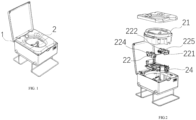
- a commode chair capable of closing a trash bag includes: a commode chair body 1 which includes a trash bag receiving port, a discharge port and a collection device 2 which is arranged on the lower part of the commode chair body 1.
- the collection device 2 includes: a trash bag fixing unit 21 which is used to provide a hollow trash bag 3; a bag feeding unit 22 which is arranged at the bottom of the trash bag fixing unit 21 and used to clamp two sides of the trash bag 3 and deliver the trash bag 3 downwards; and a trash bag closing mechanism which includes a transmission assembly 23, a closing assembly 24, and a heat sealing assembly 25.
- the transmission assembly 23 includes a power unit 231 and a scissor-hinge unit 232.
- the closing assembly 24 includes a first guide plate 241 arranged on the scissor-hinge unit 232 and a second guide plate 242 arranged opposite to the first guide plate 241.
- the heat sealing assembly 25 is arranged at the bottom of the closing assembly 24 and used to seal the trash bag 3.
- the commode chair can effect functions such as automatic bag feeding, automatic collection, automatic packaging, and heat sealing of excrement.
- the commode chair capable of closing the trash bag is portable and suitable for use outdoors or by children and middle-aged and elderly people.
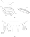
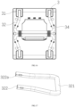
- the trash bag fixing unit 21 includes: a hollow column 211 which is used to support the hollow trash bag 3; a chassis 212 which extends outward from the bottom of the hollow column 211 horizontally and is fixed on the commode chair body 1; and a ring-shaped cover 213 covering the top of the hollow column 211.
- One end of the trash bag 3 passes around the ring-shaped cover 213 from the outer side of the hollow column 211 and enters the inner side of the hollow column 211.
- the chassis 212 further includes a surrounding side 2121 arranged upward along the edge of the chassis 212 vertically, so that the trash bag 3 will not move outward during use.
- the present device can support bag in another way without using the trash bag fixing unit 21.
- a folded soft bag is set in an annular groove of the base of the mechanism, and the ring-shaped cover 213 covers on the annular groove.
- the height of the surrounding side 2121 is 15 mm-25 mm. In the present embodiment, the height of the surrounding side 2121 is 22 mm.
- the other end of the hollow column 211 extends inwardly to form an engaging ring 2111; the ring-shaped cover 213 further includes an engaging portion 2131 matched with the engaging ring 2111.
- Ribs 2112 are uniformly and vertically arranged on the side wall of the hollow column 211.
- the trash bag fixing unit 21 further includes a sensor 214 arranged on the surface of the chassis 212 close to the ring-shaped cover 213 for detecting the supply status of the trash bag 3.
- the thickness of the material for the trash bag 3 is 0.005 mm-0.2 mm; more preferably, the thickness of the material for the trash bag 3 is 0.01 mm-0.05 mm. In the present embodiment, the thickness of the material for the trash bag 3 is 0.035 mm.
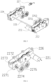
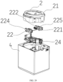
- the bag feeding unit 22 includes: a first motor 221; a first gear set 222 connected to the first motor 221; a transmission shaft 223 arranged on the first gear set 222; a second gear set 224 connected to the transmission shaft 223 and symmetrical to the first gear set 222, each gear set including a driving gear and a driven gear that cooperates with the driving gear; and a bag feeding wheel set 225 symmetrically arranged on the first gear set 222 and the second gear set 224, each bag feeding wheel set 225 including a first driving wheel 2251 arranged on the driving gear and a first driven wheel 2252 arranged on the driven gear, and the first driving wheel 2251 and the first driven wheel 2252 in each bag feeding wheel set 225 being tangent.
- the first driving wheel 2251 and the first driven wheel 2252 are arranged on the same plane.
- the bag feeding unit 22 further includes a gear installation housing 226 receiving the first gear set 222 and the second gear set 224, respectively.
- the torsion spring assembly 227 includes a straight notch 2271 arranged at the end of the gear installation housing away from the driving gear, the first driven wheel 2252 passes through the straight notch 2271 via a rotating shaft 2272 to connect to the driven gear, and the rotating shaft 2272 is sleeved with an arc-shaped stopper 2273.
- a torsion spring 2274 is arranged below the rotating shaft 2272, and the torsion spring 2274 abuts against the arc-shaped stopper 2273 to achieve a small displacement of the first driven wheel 2252 to fix the trash bag 3.
- the gear installation housing 226 also includes a torsion spring stopper 2275 arranged below the straight notch 2271. One end of the torsion spring 2274 abuts against the torsion spring stopper 2275, and the other end abuts against the arc-shaped stopper 2273.
- the design of the bag feeding unit 22 enables the driven gear to effect a small downward displacement, so that a gap is formed between the first driving wheel 2251 and the first driven wheel 2252 to allow the entry of the bag setting correction device therein. That is, the trash bag 3 is placed in the bag feeding wheel set 225, the bag setting correction device is then removed, the torsion spring 229 drives the first driven wheel 2252 to reset, and the bag feeding wheel set 225 clamps the trash bag 3 tightly.
- the replacement of the trash bag 3 of the present invention is as follows. After the trash bag 3 is used, the ring-shaped cover 213 is removed from the hollow column 211, a new trash bag 3 is taken and set on the hollow column 211, and then the ring-shaped cover 213 covers on the hollow column 211. One end of the trash bag 3 is pulled up from the outer side of the hollow column 211 to pass around the ring-shaped cover 213 and enter the inner side of the hollow column 211.
- the bag setting correction device is used to place one end of the trash bag 3 together in the bag feeding wheel set 225 and then removed for normal use.
- the ring-shaped cover 213 is removed from the base of the mechanism, the soft bag is set in the annular groove of the mechanism, and then the ring-shaped cover 213 covers. The soft bag is pulled up to pass around the ring-shaped cover and placed in the bag feeding wheel set 225 for fixation.
- a trash bag closing mechanism include:
- the power unit 231 is used to drive the scissor-hinge unit 232 to expand and contract, which consequently drives the first guide plate 241 to slide toward the second guide plate 242 to effect the closing and opening of the trash bag 3.
- the power unit 231 includes a second motor 2311 and a reducer (not labeled in the figure) connected to the second motor 2311.
- the second motor 2311 is preferably a direct current (DC) motor, which is for the purpose of reducing the cost.
- the second motor 2311 is connected to the first gear 2312.
- the scissor-hinge unit includes a fixing member 2321, and the fixing member 2321 is provided with a guide groove 23211.
- a first rack 2322 can be slidably connected to the guide groove 23211, the first gear 2312 meshes with the first rack 2322, and the first rack 2322 is connected to a scissor hinge 2323.
- the end of the fixing member 2321 away from the first gear 2312 is provided with a smooth wheel 2324.
- the smooth wheel 2324 abuts against the first rack 2322 to make the first rack 2322 run more stably and prevent the first rack 2322 from jumping vertically under force, which avoids unsmooth movement or decelerates the wear of the first rack 2322.
- the first rack is further fixed by using a gear.
- meshing teeth are arranged on both sides of the first rack 2322 and the stability of the first rack 2322 is increased by using a two-way gear fixing mode.
- the scissor hinge 2323 includes: 2 to 6 scissor sets, and the length of each scissor set increases along the direction away from the first rack 2322.
- the scissor hinge 2323 includes: 3-5 scissor sets.
- the scissor hinge 2323 includes: 4 scissor sets. Specifically, the scissor hinge 2323 includes: a first scissor set 2323a which includes two first scissor arms 2323a1.
- first scissor arm 2323a1 is rotatably arranged on the first rack 2322; a second scissor set 2323b includes two second scissor arms 2323b1 intersected, and the second scissor arms 2323b1 are each provided with a second through hole 2323b2 at the intersection.
- One end of each second scissor arm 2323b1 is rotatably connected to the other end of each first scissor arm 2323a1, respectively.
- the fixing member 2321 further includes a first bolt 23210 passing through the second through hole 2323b2, so that the second scissor arms 2323b1 can swing around the first bolt 23210 to extend the range.
- the second through hole 2323b2 is provided at the end of the second scissor arm 2323b1 close to the first scissor set 2323a, and the second scissor arm 2323b1 is divided into a second front scissor arm 2323b11 and a second rear scissor arm 2323b12, that is, the length of the second front scissor arm 2323b11 is less than that of the second rear scissor arm 2323b12.
- the first rack 2322 is moved to make the angle A between the second front scissor arms 2323b11 and the angle B between the second rear scissor arms 2323b12 equal.
- a third scissor set 2323c includes two third scissor arms 2323c1 intersected and a second bolt 2323c3, and the third scissor arms 2323c1 are each provided with a third through hole 2323c2 at the intersection.
- each third scissor arm 2323c1 is rotatably connected to the other end of each second scissor arm 2323b1, respectively, and the second bolt 2323c3 passes through the third through hole 2323c2.
- the third scissor arm exerts the function of conduction, and multiple third scissor sets 2323c can be set. In the present embodiment, one third scissor set 2323c is set.
- a fourth scissor set 2323d includes two fourth scissor arms 2323d1 intersected and a third bolt 2323d3, and the fourth scissor arms 2323d1 are each provided with a fourth elongated through hole 2323d2 at the intersection.
- One end of each fourth scissor arm 2323d1 is rotatably connected to the other end of each third scissor arm 2323c1, respectively, and the third bolt 2323d3 passes through the fourth elongated through hole 2323d2.
- the fourth elongated through hole 2323d2 is set to effect the angle change between the fourth scissor arms 2323d1 to allow the movement of the scissor hinge 2323.
- the fourth scissor arm 2323d1 also has a limit function to limit the movement of the scissor hinge 2323 within the length range of the fourth elongated through hole 2323d2.
- the stability of the scissor hinge 2323 ensures the stability of reciprocating movement.
- the length of each scissor set of the scissor hinge 2323 increases along the direction away from the first rack 2322, which reflects the range-extending effect of the transmission assembly 23, reduces the rotation of the second motor 2311 in each closing process, and achieves the effect of energy saving.
- the closing assembly 24 includes the first guide plate 241 arranged on the scissor-hinge unit 232 and the second guide plate 242 arranged opposite to the first guide plate 241.
- the first guide plate 241 slides toward the second guide plate 242 to close the trash bag.
- Both the first guide plate 241 and the second guide plate 242 have a double-layer structure.
- the first guide plate 241 includes an upper clamping sheet 2411 and a lower clamping sheet 2412.
- the second guide plate 242 is provided with an upper clamping sheet guide groove 2421 and a lower clamping sheet guide groove 2422 which are respectively adapted to the upper clamping sheet 2411 and the lower clamping sheet 2412.
- the upper clamping sheet 2411 is slidably connected to the upper clamping sheet guide groove 2421 to effect the closing of the upper part of the trash bag
- the lower clamping sheet 2412 can be slidably connected to the lower clamping sheet guide groove 2422 to effect the closing of the lower part of the trash bag, so as to more accurately seal the trash bag 3.
- the sealing stability of the trash bag is improved by the guiding function of the first guide plate 241 and the second guide plate 242.
- a guide shaft 243 is provided in a positioning hole, a first spring set 2431 is arranged at the end of the guide shaft 243 close to the first guide plate 241, and a second spring set 2432 is arranged at the end of the guide shaft 243 close to the second guide plate 242.
- the first guide plate 241 compresses the first spring set 2431.
- the power unit 231 drives the scissor-hinge unit 232 to extend out
- the first guide plate 241 under the biasing force of the first spring set 2431, tightly pushes the second guide plate 242 to eliminate the movement caused by the gap between the scissor-hinge unit 232, so that the scissor-hinge unit 232 remains in a stable state during operation.
- the scissor-hinge unit 232 will not move unless the gap between the scissor-hinge unit 232 is eliminated by movement when the power unit 231 starts. In other words, the movement of the scissor-hinge unit 232 will lag behind, resulting in unsmooth movement of the scissor-hinge unit 232 and affecting the transmission of the equipment.
- the first guide plate 241 contacts the second guide plate 242
- the second guide plate 242 compresses the second spring set 2432 to resist the force of the heat sealing assembly.
- the power unit 231 drives the scissor-hinge unit 242 to retract, and the second spring set 2432 tightly pushes the second guide plate 242 to assist in discharge.
- the heat sealing assembly 25 includes: a first heat-sealing knife 251 and a second heat-sealing knife 252 opposite to the first heat-sealing knife 251.
- the second heat-sealing knife is configured to move, driven by the transmission assembly 23, toward the first heat-sealing knife 251 to achieve the heat sealing of a closed trash bag.
- Each heat-sealing knife includes a heat-sealing knife base 2511 and a heat-sealing blade 2512 vertically connected to the heat-sealing knife base 2511.
- the first heat-sealing knife base 2511 is arranged between the upper clamping sheet guide groove 2411 and the lower clamping sheet guide groove 2412 of the first guide plate 241.
- the second heat-sealing knife base is fixed between the upper clamping sheet 2421 and the lower clamping sheet 2422 of the second guide plate 242.
- the heat sealing device further includes a heating wire (not shown in the figure), and the heating wire is arranged on the inner side of the heat-sealing knife base 2511.
- the advantages of using the present invention are as follows:
- the use of soft bag or the trash bag fixing unit 21 allows the convenient use and quick replacement of the trash bag 3.
- the symmetrically arranged bag feeding unit 22 permits synchronous bag feeding on both sides, ensuring the consistency of the movement of the trash bag 3.
- the closing assembly 24 allows the closing of the trash bag after a single use of the commode chair.
- the heat sealing assembly 25 achieves the heat sealing of the trash bag 3 being closed, completes the heating sealing and packaging of the trash bag 3, and prevents the excrement from overflowing.
- the range-extending effect of the transmission assembly 23 is achieved because the length of each scissor set of the scissor hinge 2323 increases along the direction away from the first rack 2322, which reduces the rotation of the second motor 2311 during each sealing process and achieves the effect of energy saving.
- this transmission mode of the present invention can also greatly reduce the overall cost compared to the existing mode.
- the sealing stability of the trash bag is increased through the guiding functions of the first guide plate 241, the second guide plate 242, and the guide shaft 243, and the first guide plate 241 is tightly pushed by the first spring set 2431 to eliminate the movement caused by the gap between the scissor-hinge unit 232, so that the scissor-hinge unit 232 remains in a stable state during operation.
- the second spring set 2432 is used to resist the force of the heat sealing assembly 25 to prevent the excessive large force of the heat sealing assembly 25 from melting the opening of the trash bag, which avoids breakage and odor escaping from the trash bag 3.
- the power unit 231 drives the scissor-hinge unit 232 to retract, and the second spring set 2432 tightly pushes the second guide plate 242 to prevent the heat-sealed trash bag 3 from adhering to the second guide plate to assist in discharge.
- the present invention also includes a control method for a commode chair capable of closing a trash bag, including the following steps:
- the present embodiment is basically the same as Embodiment 1 except that the power unit 231 includes a first cylinder 2313 connected to the second scissor set 2323b; the second scissor arm 2323b1 further includes a fifth through hole 2323b13 arranged at the end of the second front scissor arm 2323b11 away from the second through hole 23232, where the fifth through hole 2323b13 of one second scissor arm 2323b1 is connected to the first cylinder 2313, and the first bolt 23210 passes through the fifth through hole 2323b13 of the other second scissor arm 2323b1 to improve the stability of the scissor hinge 2323.
- the structure of the transmission assembly 23 is simplified, and the scissor hinge 2323 is driven due to the stability of the first cylinder 2313, which avoids problems such as unstable transmission and poor sealing effect caused by the large matching tolerance of the first rack 2322.
- the stand accommodating recess 311 is internally provided with a first limiting rod 313 and a second limiting rod 314 at an end proximal to the bottom plate of the commode chair body 1.
- the fixation rod 312, first limiting rod 313, and second limiting rod 314 are arranged in parallel, and the second limiting rod 314 is arranged in proximal to the end of the axis of width direction.
- the support stand assembly 3 further includes two support stands 32, each support stand 32 is arranged in a pair of mounting bases 31 that are symmetrical about an axis of length direction.
- the support stand 32 is integrally formed by bending a round tube.
- the support stand 32 includes a support part 321 and mounting parts 322 arranged at two ends of the support part 321.
- the mounting parts 322 are symmetrical about the support part 321.
- Through holes 322a having an elongate slot shape are arranged on the sidewall of the mounting parts 322.
- the diameter of the fixation rod 312 is smaller than the width of the through hole 322a.
- the fixation rod 312 is arranged in the through hole 322a to enable the support stand 32 to rotate about the fixation rod 312, so as to achieve the function of folding and unfolding the support stand 32.
- a limiting spring 33 is provided inside the tube wall of each mounting part 322.
- One end of the limiting spring 33 abuts a tail end of the mounting part 322, and another end of the limiting spring 33 abuts the fixation rod 312.
- the fixation rod 312 is slidable inside the through hole 322a with elongate slot shape.
- the rectangular bottom plate of the commode chair body 1 is provided with four clamps 34, and the clamps 34 are configured to secure the tube wall of the mounting parts 322.
- the clamps can secure the tube wall of the mounting parts 322 and the support stand 32 cannot rotate anymore, so as to achieve the folding and securing of the support stand 32 and facilitate the remove of the commode chair.
- the support stand 32 is detached from the clamps 34, then the limiting spring 33 is compressed to make the fixation rod 312 slide to a side of the through hole 322a proximal to the tail end of the mounting part 322, such that the tail end of the mounting part 322 rotates to pass through a space between the first limiting rod 313 and an end proximal to the opening of the stand accommodating recess 311.
- the limiting spring 33 is reset, and the fixation rod 312 slides to a side of the through hole 322a away from the tail end of the mounting part 322.
- the mounting part 322 is secured between the first limiting rod 313 and the second limiting rod 314, the tube diameter of the mounting part 322 is equal to the distance between the first limiting rod 313 and the second limiting rod 314.
- the two support stands 32 prop up the commode chair body 1. The installation and configuration of the support stand assembly 3 can facilitate the remove and storage of the commode chair.
- the present embodiment is different from the above trash bag closing mechanism embodiments in that a fordable support stand assembly 3 is provided at the bottom of the commode chair body 1.
- the support stand assembly 3 includes mounting brackets 35 which are symmetrically arranged on the rectangular bottom plate of the commode chair body 1.
- the mounting brackets 35 are arranged at a side of the rectangular bottom plate proximal to a cover plate of the commode chair.
- the mounting brackets 35 are symmetric about an axis of length direction of the rectangular bottom plate.
- Each mounting bracket 35 is provided with a first stand sleeve 36 in hinge connection.
- the first stand sleeve 36 is slidably connected around a first stand 37.
- the first stand 37 is a tubular structure with a U-shaped cross section.
- the first stand sleeves 36 of the mounting brackets 35 are connected around the tube wall of the first stand 37 at two sides.
- the bottom part of the first stand 37 is configured to support the commode chair, and the top part of the first stand 37, namely, the opening of the U-shaped structure, is connected with a second stand sleeve 38 in sleeve manner.
- the second stand sleeve 28 is slidably connected with a second stand 39.
- the second stand 39 is a tubular structure with a closed loop shape.
- the second stand 39 includes a connecting end 391 and a support end 392 arranged in opposite to the connecting end 391.
- the second stand sleeve 38 sleeves around the connecting end 391 of the second stand 39.
- the wall of the tube between the connecting end 391 and the support end 392 is provided with through holes for connecting the rectangular bottom plate of the commode chair body 1 at an end away from the mounting brackets 35 by bolts, and the second stand 39 is rotatable about the bolts.
- the connecting end 391 and support end 392 of the second stand 39 are located at the same height.
- the first stand sleeve 36 slid to an end proximal to the second stand sleeve 38, the first stand 37 is parallel to the ground plane, and the commode chair is propped up by the connecting end 391 and the support end 392 of the second stand 39.
- the second stand 39 rotates about the bolts and the connecting end 391 moves toward the cover plate of the commode chair.
- the second stand sleeve 38 rotates to make the first stand sleeve 36 slide to an end away from the second stand sleeve 38, and the first stand 37 follows the rotation.
- the tube wall at two sides of the first stand 37 are provided with limiting pins 371.
- the first stand sleeve 36 abuts the limiting pin 371, the bottom part of the first stand 37 and the support end 392 of the second stand 39 serve as supporting points and prop up the whole commode chair.
- the installation and configuration of the support stand assembly 3 can facilitate the remove and storage of the commode chair.
- the present embodiment is different from the above trash bag closing mechanism embodiments in that the power unit 231 includes an installation component 2331 fixed on the commode chair.
- the installation component 2331 is a detachable installation casing.
- a third motor 2332 is transversely disposed at a side close to the top of the installation component 2331, and the third motor 2332 is connected to a speed reducer (not labelled in the drawing).
- the third motor 2332 is a DC motor
- the use of the DC motor can reduce cost, and since the DC motor has reduction gear box which has fixed reduction ratio, the output speed is fixed, by controlling the operation time of the motor through PCB, the number of rotation turns can be controlled, and by controlling the input current of the motor, the output torque can be controlled.
- the third motor 2332 is configured to drive a second gear 2333 in the installation component 2331, and the second gear 2333 is engaged with a third gear 2334.
- the installation component 2331 is provided with a positioning groove 23311 below the third gear 2334.
- a second rack 2335 is accommodated in the positioning groove 23311, and the second rack 2335 is engaged with the third gear 2334.
- the second rack 2335 is connected to the scissor-hinge unit 232.
- the configuration that the third motor 2332 is transversely disposed at a side close to the top of the installation component 2331 facilitates the wiring of the device, and the configuration that the second rack 2335 is located below the third gear 2334 can reduce the height of the installation component 2331, such that the structure is more compact, the volume of the commode chair is reduced, it is more convenient to move the commode chair at night and easier to carry the commode chair outdoors or during traveling, and the bag feeding distance of the bag feeding unit 22 can be shortened, thus reducing energy consumption.
- An angle A formed by a line connecting the center of the second gear 2333 and the center of the third gear 2334 and the ground plane ranges 60-80°.
- the angle A formed by the line connecting the center of the first gear 2312 and the center of the second gear 2313 and the ground plane is 75°.
- the third motor 2332 should be positioned near the top of the installation component 2331, if a single gear is used to engage with a rack, collision may be caused between the bag feeding unit 22 and the trash bag closing mechanism. Accordingly, in the present embodiment, two gears engaged with each other are used to drive the scissor-hinge unit 232 to move, which can reduce friction caused by mechanical movement.
- the overall height of the bag feeding unit 22 is 200mm
- the height of the first guide plate 241 is 120mm
- the overall height of the fixing member 2321 is 320mm
- the distance between the bottom of the bag feeding unit 22 and the top of the first guide plate 241 is 10mm.
- the configuration of the present embodiment can effectively reduce the height of the installation component 2331 by 100mm, and the distance between the bag feeding unit 22 and the trash bag closing mechanism is short, such that the structure is more compact, energy consumed by the bag feeding unit during the feeding of the bag can be reduced, the volume can be reduced, and it is more convenient to move.
- the sidewall of the positioning groove 23311 is provided with a limiting block 23311a
- the second rack 2335 is provided with a limiting groove 2335a matched with the limiting block 23311a.
- the limiting block 23311a is slidably connected with the limiting groove 2335a.
- the bottom of the second rack 2335 is symmetrically provided with two limiting steps 2335b, and the bottom of the positioning groove 23311 is provided with step grooves 23311b matched with the limiting steps 2335b.
- the limiting steps 2335b are slidably connected with the step grooves 23311b.
- a smooth wheel is provided above the second rack 2335, the smooth wheel abuts against the second rack 2335 so as to prevent the second rack 2335 from jumping vertically under force.
- the smooth wheel may get stuck or interfered during operation, which would render the movement of the second rack 2335 not going smoothly.
- the smooth wheel is replaced with two symmetrically arranged limiting steps 2335b located at the bottom of the second rack 2335, the connection between the limiting steps 2335b and the step grooves 23311b can make the operation smoother and prevent the second rack 2335 from jumping vertically under force.
- the transverse arrangement of the third motor 2332 can facilitate wiring of the commode chair.
- the battery assembly 26 may be installed inside the hollow column 211.
- the battery assembly 26 includes a battery installation housing 261 installed at a lower end of the hollow column 211.
- the battery installation housing 261 is an integrally molded plastic casing. The use of plastic casing can reduce cost. Since the battery is relatively light, the plastic casing made of PC material can make sure that the battery installation housing 261 has enough installation strength.
- the battery installation housing 261 includes battery accommodating groove 2611, the battery 262 is installed in the battery accommodating groove 2611. Two ends of the battery accommodating groove 2611 are provided with installation parts 2612 for being fixed on the bottom of the hollow column 211.
- the installation parts 2612 are fixed on the hollow column 211 by bolts, the battery assembly 26 is configured inside the hollow column 211, such that the overall structure of the commode chair is more compact and the volume of the commode chair is reduced.
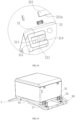
- the present invention further provides a trash container, including:
- the shape and structure of the trash container body 4 are not limited and can be selected according to actual needs. For example, it may be a cuboid, a cube, or the like.
- the trash container body 4 is a cuboid, and the trash bag receiving port is set at the top of the cuboid, and the discharge port is set on the side wall of the cuboid (not shown in the figure).
- a control method for a trash container includes the following steps:
- the trash bag closing mechanism further includes a heat sealing assembly which is arranged on the first guide plate 241 and/or the second guide plate 242, and the control method further includes: S60: heat sealing through the range-extending trash bag closing mechanism.
Landscapes
- Engineering & Computer Science (AREA)
- Mechanical Engineering (AREA)
- Health & Medical Sciences (AREA)
- Public Health (AREA)
- Refuse Receptacles (AREA)
- Package Closures (AREA)
Claims (8)
- ein Müllbeutelverschlussmechanismus, dadurch gekennzeichnet, dass:eine übertragungseinheit (23) umfassend eine Antriebseinheit (231) und eine Schere-Scharniereinheit (232);eine Verschlussanordnung (24), umfassend eine an der Schere-Scharniereinheit (232) angeordnete erste Führungsplatte (241) und eine gegenüber der ersten Führungsplatte (241) angeordnete zweite Führungsplatte (242); undeine an der ersten Führungsplatte (241) und/oder der zweiten Führungsplatte (242)) angeordnete Wärmedichtungsanordnung (25), die zum Wärmedichten eines geschlossenen Müllsacks (3) verwendet wird;wobei die Antriebseinheit (231) verwendet wird, um die Schere-Scharniereinheit (232) zum Ausdehnen und Zusammenziehen zu antreiben, was die erste Führungsplatte (241) zum Gleiten zur zweiten Führungsplatte (242) antreibt, um das Schließen und Öffnen des Müllbeutels (3) zu bewirken; gekennzeichnet dadurch, dass:
die Antriebseinheit umfasst einen zweiten Motor (2311) und ein mit dem zweiten Motor (2311) verbundenes erstes Getriebe (2312); die Schere-Scharniereinheit (232) umfasst ein Befestigungselement (2321), eine am Befestigungselement (2321) angeordnete Führungsnut (23211), eine in der Führungsnut (23211) aufgenommene und mit dem ersten Zahnrad (2312) eingegriffene erste Zahnstange (2322) und ein mit der ersten Zahnstange (2322) verbundenes Schere-Scharnier (2323); und dadurch gekennzeichnet, dass das Scherscharnier (2323) 2 bis 6 Scherensätze umfasst, und dass die Länge jedes Scherensätzes entlang der Richtung weg vom ersten Gestell (2322) zunimmt. - Müllbeutelverschlussmechanismus nach einem der Ansprüche 1 bis 3, dadurch gekennzeichnet, dass das Scherscharnier:ein erster Schereset (2323a), wobei der erste Schereset (2323a) zwei erste Scherearme (2323a1) und ein Ende des ersten Scherearmes (2323al) umfasst, das drehbar auf der ersten Gestelle (2322) angeordnet ist;ein zweiter Schereset (2323b), wobei der zweite Schereset zwei zweite Scherearme (2323b1) umfasst, die sich kreuzen, und die zweiten Scherearme (2323b1) jeweils an der Kreuzung mit einem zweiten Durchgangsloch (2323b2) versehen sind; ein Ende jedes zweiten Scherearms (2323b1) mit dem anderen Ende jedes ersten Scherearms (2323a1) drehbar verbunden ist, wobei das Befestigungselement (2321) ferner einen ersten Bolzen (23210) umfasst, der durch das zweite Durchgangsloch (2323b2) hindurchgeht, dass die zweiten Scherearme (2323b1) um den ersten Bolzen (23210) schwenkbar sind, um den Bereich zu erweitern.
- Müllbeutelverschlussmechanismus nach Anspruch 2, dadurch gekennzeichnet, dass das Scherscharnier (2323) ferner umfasst:ein dritter Schereset (2323c), wobei der dritte Schereset (2323c) zwei geschnittene dritte Scherearme (2323cl) und einen zweiten Bolzen (2323c3) umfasst, und die dritten Scherearme (2323cl) jeweils an der Schnittstelle mit einem dritten Durchgangsloch (2323c2) versehen sind, ein Ende jedes dritten Scherearmes (2323cl) jeweils drehbar mit dem anderen Ende jedes zweiten Scherearmes (2323b1) verbunden ist und der zweite Bolzen (2323c3) durch das dritte Durchgangsloch (2323c2) geht;ein vierter Scherensatz (2323d), wobei der vierte Scherensatz (2323d) zwei geschnittene vierte Scherearme (2323d1) und einen dritten Bolzen (2323d3) umfasst, und die vierten Scherearme (2323d1) jeweils an der Kreuzung mit einem vierten länglichen Durchgangsloch (2323d2) versehen sind, ein Ende jedes vierten Scherearmes (2323d1) jeweils drehbar mit dem anderen Ende jedes dritten Scherearmes (2323c1) verbunden ist und der dritte Bolzen (2323d1) durch das vierte längliche Durchgangsloch (2323d2) geht.
- Müllbeutelverschlussmechanismus nach Anspruch 1, dadurch gekennzeichnet, dass sowohl die erste Führungsplatte (241) als auch die zweite Führungsplatte (242) eine doppelschichtige Struktur aufweisen, die erste Führungsplatte (241) ein oberes Klemmblech (2411) und ein unteres Klemmblech (2412) umfasst, die zweite Führungsplatte (242) mit einer oberen Klemmblechführungsnut (2421) und einer unteren Klemmblechführungsnut (2422) versehen ist, die jeweils an das obere Klemmblech (2411) und das untere Klemmblech (2412) angepasst sind, das obere Klemmblech (2411) mit der oberen Klemmblechführungsnut (2421) gleitbar verbunden ist, um den oberen Teil des Müllbeutels (3) zu schließen, und das untere Klemmblech (2412) gleitbar mit der unteren Klemmblechführungsnut (2422) verbunden ist, um den unteren Teil des Müllbeutels (3) zu schließen.
- Müllsackschlussmechanismus nach Anspruch 4, dadurch gekennzeichnet, dass jeweils zwei Seiten der ersten Führungsplatte (241) und der zweiten Führungsplatte (242) mit Positionierungslöchern versehen sind, eine Führungswelle (243) in den Positionierungslöchern aufgenommen ist, ein erster Federsatz (2431) am Ende der Führungswelle (243) nahe der ersten Führungsplatte (241) angeordnet ist und ein zweiter Federsatz (2432) am Ende der Führungswelle (243) nahe der zweiten Führungsplatte (242) angeordnet ist, im Ausgangszustand befinden sich die Scherscharniereinheit (232) und die Antriebseinheit (231) in einem Spannungszustand, die erste Führungsplatte (241) komprimiert den ersten Federsatz (2431), wenn die Antriebseinheit (231) die Scherscharniereinheit (232) zum Ausdehnen antreibt, die erste Führungsplatte (241) unter der Vorspannkraft des ersten Federsatzes (2431) die zweite Führungsplatte (242) fest drückt, um die durch den Spalt zwischen der Scherscharniereinheit (232) verursachte, so dass die Schere-Scharniereinheit (232) während des Betriebs in einem stabilen Zustand bleibt, wenn die erste Führungsplatte (241) die zweite Führungsplatte (242) berührt, die zweite Führungsplatte (242) den zweiten Federsatz (2432) zusammendrückt, um der Kraft der Wärmedichtungsanordnung zu widerstehen, nach Abschluss der Wärmedichtung treibt die Antriebseinheit (231) die Schere-Scharniereinheit (232) zum Rückzug an und der zweite Federsatz (2432) die zweite Führungsplatte (242) fest drückt, um die Entladung zu unterstützen.
- Paketförmiger Komodenstuhl, umfassend:einen Komodenstuhlkörper (I), der einen Müllsack-Aufnahmeöffnung und einen Ablauföffnung umfasst;eine an der Müllbeutelaufnahmeöffnung angeordnete Müllbeutelbefestigungseinheit (21) zur Aufbewahrung hohler Müllbeutel;eine unter der Müllbeutelbefestigungseinheit angeordnete Beutelfeedereinheit (22) und ein Müllbeutelverschlussmechanismus nach Anspruch 1, der unter der Beutelfeedereinheit angeordnet ist.
- Steuerverfahren für den Packstuhl nach Anspruch 6, dadurch gekennzeichnet, dass:S10: Befestigung des Müllbeutels (3) an der Müllbeutelbefestigungseinheit (21);S20: den Müllbeutel (3) aus der Müllbeutelbefestigungseinheit (2I) durch die Beutelfeedereinheit (22) herausziehen;S30: den Müllbeutel (3) in einem vorbestimmten Abstand durch die Beutelfeedereinheit (22) zuführen;S40: nach dem Gebrauch durch den Müllbeutelverschlussmechanismus verschließen und wärmeversiegeln;S50: den Müllsack (3) im vorbestimmten Abstand wieder durch die Beutelfeedereinheit zuführen.
- Ein Müllbehälter, umfassend:einen Müllbehälterkörper (4), der einen Müllbeutelaufnahmeöffnung und einen Entladungsöffnung umfasst;eine an der Müllbeutelaufnahmeöffnung angeordnete Müllbeutelbefestigungseinheit (21) zur Aufbewahrung hohler Müllbeutel;eine unter der Müllbeutelbefestigungseinheit angeordnete Beutelfeedereinheit (22); undMüllbeutelverschlussmechanismus nach Anspruch 1, der unter der Beutelfeedereinheit (22) angeordnet ist.
Applications Claiming Priority (1)
| Application Number | Priority Date | Filing Date | Title |
|---|---|---|---|
| CN202310084180.5A CN116353996A (zh) | 2023-01-31 | 2023-01-31 | 垃圾袋缩口机芯、坐便椅、垃圾桶及其控制 |
Publications (2)
| Publication Number | Publication Date |
|---|---|
| EP4410165A1 EP4410165A1 (de) | 2024-08-07 |
| EP4410165B1 true EP4410165B1 (de) | 2025-06-25 |
Family
ID=86905377
Family Applications (1)
| Application Number | Title | Priority Date | Filing Date |
|---|---|---|---|
| EP23186085.9A Active EP4410165B1 (de) | 2023-01-31 | 2023-07-18 | Verschlussmechanismus für müllbeutel, toilettenstuhl, müllbehälter und seine steuerung |
Country Status (5)
| Country | Link |
|---|---|
| US (1) | US12495939B2 (de) |
| EP (1) | EP4410165B1 (de) |
| JP (1) | JP3242693U (de) |
| CN (1) | CN116353996A (de) |
| WO (1) | WO2024159571A1 (de) |
Families Citing this family (5)
| Publication number | Priority date | Publication date | Assignee | Title |
|---|---|---|---|---|
| CN116331695B (zh) * | 2023-01-31 | 2025-04-18 | 汇沅东(厦门)健康科技有限公司 | 一种垃圾袋缩口机芯及垃圾桶及控制 |
| USD1066614S1 (en) * | 2023-06-29 | 2025-03-11 | Huiyuandong (xiamen) Health Technology Co., Ltd. | Portable toilet |
| CN118697222A (zh) * | 2024-07-31 | 2024-09-27 | 汇沅东(厦门)健康科技有限公司 | 一种智能座便器及其打包控制方法 |
| CN118744845B (zh) * | 2024-08-14 | 2026-04-24 | 永州雅力德科技有限公司 | 容纳桶 |
| CN119329849B (zh) * | 2024-11-07 | 2026-03-27 | 深圳市多特智能高科有限公司 | 一种对废弃物进行自动打包分切的设备 |
Family Cites Families (16)
| Publication number | Priority date | Publication date | Assignee | Title |
|---|---|---|---|---|
| JP2016037307A (ja) * | 2014-08-08 | 2016-03-22 | 酒井医療株式会社 | フィルム密封装置およびフィルム密封式便座装置 |
| CN206542115U (zh) * | 2016-10-31 | 2017-10-03 | 广西电网有限责任公司电力科学研究院 | 一种角度连续可调螺旋自锁式高压输电线路接地线夹 |
| CN206798320U (zh) * | 2017-06-12 | 2017-12-26 | 山东协和学院 | 一种智能打包垃圾桶 |
| CN110367866A (zh) * | 2019-08-20 | 2019-10-25 | 任昱霖 | 一种自动收集坐便椅 |
| CN210784133U (zh) * | 2019-08-20 | 2020-06-19 | 厦门市西文机械工贸有限公司 | 一种热封袋口装置 |
| CN211141400U (zh) * | 2019-12-24 | 2020-07-31 | 焦凤芹 | 一种车辆省力抬升架 |
| CN111645611A (zh) * | 2020-07-07 | 2020-09-11 | 杨金华 | 一种免冲洗如厕结构及固定式、升降式免冲洗如厕系统 |
| CN216071515U (zh) * | 2020-11-16 | 2022-03-18 | 上海青宇科技有限公司 | 一种用于智能打包坐便器的塑料袋打包机构 |
| CN217456602U (zh) * | 2021-04-26 | 2022-09-20 | 灵鹿智能科技(台州)有限公司 | 一种塑料袋热熔防粘连结构及垃圾桶和坐便器 |
| CN113353514A (zh) * | 2021-07-12 | 2021-09-07 | 西安医学院第二附属医院 | 一种便于固定垃圾袋可自动打包消毒的医用垃圾桶 |
| CN114043499A (zh) * | 2021-12-02 | 2022-02-15 | 西南石油大学 | 家庭宠物粪便清理机器人 |
| CN114933102A (zh) * | 2022-05-20 | 2022-08-23 | 湘潭大学 | 一种自动封装和换袋的垃圾桶 |
| CN114890012B (zh) * | 2022-07-13 | 2022-12-20 | 江苏环亚医用科技集团股份有限公司 | 一种用于医疗术后污物用垃圾包装机 |
| CN116331695B (zh) * | 2023-01-31 | 2025-04-18 | 汇沅东(厦门)健康科技有限公司 | 一种垃圾袋缩口机芯及垃圾桶及控制 |
| CN219097671U (zh) * | 2023-01-31 | 2023-05-30 | 汇沅东(厦门)健康科技有限公司 | 一种垃圾袋缩口机芯及垃圾桶 |
| CN218899287U (zh) * | 2023-02-03 | 2023-04-25 | 汇沅东(厦门)健康科技有限公司 | 一种便捷打开卸料板的坐便椅 |
-
2023
- 2023-01-31 CN CN202310084180.5A patent/CN116353996A/zh active Pending
- 2023-03-01 WO PCT/CN2023/078979 patent/WO2024159571A1/zh not_active Ceased
- 2023-03-31 US US18/129,084 patent/US12495939B2/en active Active
- 2023-05-08 JP JP2023001529U patent/JP3242693U/ja active Active
- 2023-07-18 EP EP23186085.9A patent/EP4410165B1/de active Active
Also Published As
| Publication number | Publication date |
|---|---|
| US12495939B2 (en) | 2025-12-16 |
| CN116353996A (zh) | 2023-06-30 |
| EP4410165A1 (de) | 2024-08-07 |
| WO2024159571A1 (zh) | 2024-08-08 |
| JP3242693U (ja) | 2023-07-06 |
| US20240252001A1 (en) | 2024-08-01 |
Similar Documents
| Publication | Publication Date | Title |
|---|---|---|
| EP4410165B1 (de) | Verschlussmechanismus für müllbeutel, toilettenstuhl, müllbehälter und seine steuerung | |
| CN116331695A (zh) | 一种垃圾袋缩口机芯及垃圾桶及控制 | |
| CN210291144U (zh) | 一种非开挖式管道局部修复装置 | |
| US20080282911A1 (en) | Waste Bin Having Compacting Means | |
| CN213246343U (zh) | 一种能够展开收起的便携式宠物粪便收集装置 | |
| CN218899287U (zh) | 一种便捷打开卸料板的坐便椅 | |
| CN108839979B (zh) | 一种内置封口胶带的自动抽袋式垃圾桶 | |
| CN211632353U (zh) | 一种折叠式床上化妆台 | |
| CN207882645U (zh) | 一种横向开合平行活动铰剪支承式回卷投影幕 | |
| CN216201769U (zh) | 一种医疗设备环境智能漏水探查器 | |
| CN217075436U (zh) | 一种联动结构及遮阳装置 | |
| CN216882357U (zh) | 一种钣金焊接用防倾倒装置 | |
| CN216841410U (zh) | 多功能钢杆施工爬梯辅助架 | |
| CN116439594A (zh) | 一种单电机驱动坐便椅及其控制方法 | |
| CN214219525U (zh) | 一种展收折叠式物品收集卸载装置 | |
| CN115591878A (zh) | 一种圆管清淤机器人 | |
| CN217999287U (zh) | 一种用于橱柜的多功能铰链 | |
| KR200390896Y1 (ko) | 절첩시 승강되어지는 네트를 갖는 미니 탁구대 | |
| CN210597504U (zh) | 一种水槽垃圾装袋机 | |
| CN221013079U (zh) | 一种单电机驱动坐便椅 | |
| CN223341507U (zh) | 智能垃圾桶 | |
| CN221606758U (zh) | 一种自动收袋打包的垃圾桶 | |
| CN220640546U (zh) | 一种衣物折叠装置 | |
| CN216570528U (zh) | 一种神经外科用医疗床 | |
| CN223314555U (zh) | 一种纸盒折叠机构 |
Legal Events
| Date | Code | Title | Description |
|---|---|---|---|
| PUAI | Public reference made under article 153(3) epc to a published international application that has entered the european phase |
Free format text: ORIGINAL CODE: 0009012 |
|
| STAA | Information on the status of an ep patent application or granted ep patent |
Free format text: STATUS: THE APPLICATION HAS BEEN PUBLISHED |
|
| AK | Designated contracting states |
Kind code of ref document: A1 Designated state(s): AL AT BE BG CH CY CZ DE DK EE ES FI FR GB GR HR HU IE IS IT LI LT LU LV MC ME MK MT NL NO PL PT RO RS SE SI SK SM TR |
|
| STAA | Information on the status of an ep patent application or granted ep patent |
Free format text: STATUS: REQUEST FOR EXAMINATION WAS MADE |
|
| 17P | Request for examination filed |
Effective date: 20240919 |
|
| RBV | Designated contracting states (corrected) |
Designated state(s): AL AT BE BG CH CY CZ DE DK EE ES FI FR GB GR HR HU IE IS IT LI LT LU LV MC ME MK MT NL NO PL PT RO RS SE SI SK SM TR |
|
| RIN1 | Information on inventor provided before grant (corrected) |
Inventor name: DENG, YUNJIANG |
|
| GRAP | Despatch of communication of intention to grant a patent |
Free format text: ORIGINAL CODE: EPIDOSNIGR1 |
|
| STAA | Information on the status of an ep patent application or granted ep patent |
Free format text: STATUS: GRANT OF PATENT IS INTENDED |
|
| RIC1 | Information provided on ipc code assigned before grant |
Ipc: B65B 51/10 20060101ALN20250107BHEP Ipc: A47K 11/04 20060101ALN20250107BHEP Ipc: B65B 67/12 20060101ALI20250107BHEP Ipc: B65F 1/06 20060101ALI20250107BHEP Ipc: B65B 51/14 20060101ALI20250107BHEP Ipc: A47K 11/02 20060101AFI20250107BHEP |
|
| INTG | Intention to grant announced |
Effective date: 20250121 |
|
| GRAS | Grant fee paid |
Free format text: ORIGINAL CODE: EPIDOSNIGR3 |
|
| GRAA | (expected) grant |
Free format text: ORIGINAL CODE: 0009210 |
|
| STAA | Information on the status of an ep patent application or granted ep patent |
Free format text: STATUS: THE PATENT HAS BEEN GRANTED |
|
| AK | Designated contracting states |
Kind code of ref document: B1 Designated state(s): AL AT BE BG CH CY CZ DE DK EE ES FI FR GB GR HR HU IE IS IT LI LT LU LV MC ME MK MT NL NO PL PT RO RS SE SI SK SM TR |
|
| REG | Reference to a national code |
Ref country code: GB Ref legal event code: FG4D |
|
| REG | Reference to a national code |
Ref country code: CH Ref legal event code: EP |
|
| REG | Reference to a national code |
Ref country code: CH Ref legal event code: EP |
|
| REG | Reference to a national code |
Ref country code: IE Ref legal event code: FG4D |
|
| REG | Reference to a national code |
Ref country code: DE Ref legal event code: R096 Ref document number: 602023004244 Country of ref document: DE |
|
| PG25 | Lapsed in a contracting state [announced via postgrant information from national office to epo] |
Ref country code: FI Free format text: LAPSE BECAUSE OF FAILURE TO SUBMIT A TRANSLATION OF THE DESCRIPTION OR TO PAY THE FEE WITHIN THE PRESCRIBED TIME-LIMIT Effective date: 20250625 |
|
| PGFP | Annual fee paid to national office [announced via postgrant information from national office to epo] |
Ref country code: DE Payment date: 20250723 Year of fee payment: 3 |
|
| REG | Reference to a national code |
Ref country code: LT Ref legal event code: MG9D |
|
| PG25 | Lapsed in a contracting state [announced via postgrant information from national office to epo] |
Ref country code: NO Free format text: LAPSE BECAUSE OF FAILURE TO SUBMIT A TRANSLATION OF THE DESCRIPTION OR TO PAY THE FEE WITHIN THE PRESCRIBED TIME-LIMIT Effective date: 20250925 Ref country code: GR Free format text: LAPSE BECAUSE OF FAILURE TO SUBMIT A TRANSLATION OF THE DESCRIPTION OR TO PAY THE FEE WITHIN THE PRESCRIBED TIME-LIMIT Effective date: 20250926 |
|
| PG25 | Lapsed in a contracting state [announced via postgrant information from national office to epo] |
Ref country code: BG Free format text: LAPSE BECAUSE OF FAILURE TO SUBMIT A TRANSLATION OF THE DESCRIPTION OR TO PAY THE FEE WITHIN THE PRESCRIBED TIME-LIMIT Effective date: 20250625 |
|
| PG25 | Lapsed in a contracting state [announced via postgrant information from national office to epo] |
Ref country code: HR Free format text: LAPSE BECAUSE OF FAILURE TO SUBMIT A TRANSLATION OF THE DESCRIPTION OR TO PAY THE FEE WITHIN THE PRESCRIBED TIME-LIMIT Effective date: 20250625 |
|
| PGFP | Annual fee paid to national office [announced via postgrant information from national office to epo] |
Ref country code: FR Payment date: 20250807 Year of fee payment: 3 Ref country code: AT Payment date: 20251020 Year of fee payment: 3 |
|
| PG25 | Lapsed in a contracting state [announced via postgrant information from national office to epo] |
Ref country code: RS Free format text: LAPSE BECAUSE OF FAILURE TO SUBMIT A TRANSLATION OF THE DESCRIPTION OR TO PAY THE FEE WITHIN THE PRESCRIBED TIME-LIMIT Effective date: 20250925 |
|
| PG25 | Lapsed in a contracting state [announced via postgrant information from national office to epo] |
Ref country code: LV Free format text: LAPSE BECAUSE OF FAILURE TO SUBMIT A TRANSLATION OF THE DESCRIPTION OR TO PAY THE FEE WITHIN THE PRESCRIBED TIME-LIMIT Effective date: 20250625 |
|
| REG | Reference to a national code |
Ref country code: NL Ref legal event code: MP Effective date: 20250625 |
|
| PG25 | Lapsed in a contracting state [announced via postgrant information from national office to epo] |
Ref country code: NL Free format text: LAPSE BECAUSE OF FAILURE TO SUBMIT A TRANSLATION OF THE DESCRIPTION OR TO PAY THE FEE WITHIN THE PRESCRIBED TIME-LIMIT Effective date: 20250625 |
|
| PG25 | Lapsed in a contracting state [announced via postgrant information from national office to epo] |
Ref country code: PT Free format text: LAPSE BECAUSE OF FAILURE TO SUBMIT A TRANSLATION OF THE DESCRIPTION OR TO PAY THE FEE WITHIN THE PRESCRIBED TIME-LIMIT Effective date: 20251027 |
|
| REG | Reference to a national code |
Ref country code: AT Ref legal event code: MK05 Ref document number: 1805558 Country of ref document: AT Kind code of ref document: T Effective date: 20250625 |
|
| PG25 | Lapsed in a contracting state [announced via postgrant information from national office to epo] |
Ref country code: IS Free format text: LAPSE BECAUSE OF FAILURE TO SUBMIT A TRANSLATION OF THE DESCRIPTION OR TO PAY THE FEE WITHIN THE PRESCRIBED TIME-LIMIT Effective date: 20251025 |
|
| PG25 | Lapsed in a contracting state [announced via postgrant information from national office to epo] |
Ref country code: AT Free format text: LAPSE BECAUSE OF FAILURE TO SUBMIT A TRANSLATION OF THE DESCRIPTION OR TO PAY THE FEE WITHIN THE PRESCRIBED TIME-LIMIT Effective date: 20250625 Ref country code: SM Free format text: LAPSE BECAUSE OF FAILURE TO SUBMIT A TRANSLATION OF THE DESCRIPTION OR TO PAY THE FEE WITHIN THE PRESCRIBED TIME-LIMIT Effective date: 20250625 |
|
| PG25 | Lapsed in a contracting state [announced via postgrant information from national office to epo] |
Ref country code: CZ Free format text: LAPSE BECAUSE OF FAILURE TO SUBMIT A TRANSLATION OF THE DESCRIPTION OR TO PAY THE FEE WITHIN THE PRESCRIBED TIME-LIMIT Effective date: 20250625 |
|
| PG25 | Lapsed in a contracting state [announced via postgrant information from national office to epo] |
Ref country code: PL Free format text: LAPSE BECAUSE OF FAILURE TO SUBMIT A TRANSLATION OF THE DESCRIPTION OR TO PAY THE FEE WITHIN THE PRESCRIBED TIME-LIMIT Effective date: 20250625 |
|
| PG25 | Lapsed in a contracting state [announced via postgrant information from national office to epo] |
Ref country code: EE Free format text: LAPSE BECAUSE OF FAILURE TO SUBMIT A TRANSLATION OF THE DESCRIPTION OR TO PAY THE FEE WITHIN THE PRESCRIBED TIME-LIMIT Effective date: 20250625 |
|
| PG25 | Lapsed in a contracting state [announced via postgrant information from national office to epo] |
Ref country code: SK Free format text: LAPSE BECAUSE OF FAILURE TO SUBMIT A TRANSLATION OF THE DESCRIPTION OR TO PAY THE FEE WITHIN THE PRESCRIBED TIME-LIMIT Effective date: 20250625 |
|
| PG25 | Lapsed in a contracting state [announced via postgrant information from national office to epo] |
Ref country code: ES Free format text: LAPSE BECAUSE OF FAILURE TO SUBMIT A TRANSLATION OF THE DESCRIPTION OR TO PAY THE FEE WITHIN THE PRESCRIBED TIME-LIMIT Effective date: 20250625 |
|
| PG25 | Lapsed in a contracting state [announced via postgrant information from national office to epo] |
Ref country code: LU Free format text: LAPSE BECAUSE OF NON-PAYMENT OF DUE FEES Effective date: 20250718 Ref country code: RO Free format text: LAPSE BECAUSE OF FAILURE TO SUBMIT A TRANSLATION OF THE DESCRIPTION OR TO PAY THE FEE WITHIN THE PRESCRIBED TIME-LIMIT Effective date: 20250625 |
|
| REG | Reference to a national code |
Ref country code: BE Ref legal event code: MM Effective date: 20250731 |
|
| PG25 | Lapsed in a contracting state [announced via postgrant information from national office to epo] |
Ref country code: MC Free format text: LAPSE BECAUSE OF FAILURE TO SUBMIT A TRANSLATION OF THE DESCRIPTION OR TO PAY THE FEE WITHIN THE PRESCRIBED TIME-LIMIT Effective date: 20250625 |
|
| PG25 | Lapsed in a contracting state [announced via postgrant information from national office to epo] |
Ref country code: DK Free format text: LAPSE BECAUSE OF FAILURE TO SUBMIT A TRANSLATION OF THE DESCRIPTION OR TO PAY THE FEE WITHIN THE PRESCRIBED TIME-LIMIT Effective date: 20250625 |
|
| PG25 | Lapsed in a contracting state [announced via postgrant information from national office to epo] |
Ref country code: BE Free format text: LAPSE BECAUSE OF NON-PAYMENT OF DUE FEES Effective date: 20250731 Ref country code: IT Free format text: LAPSE BECAUSE OF FAILURE TO SUBMIT A TRANSLATION OF THE DESCRIPTION OR TO PAY THE FEE WITHIN THE PRESCRIBED TIME-LIMIT Effective date: 20250625 |