EP4409205B1 - Wasserheizungsanlage - Google Patents
Wasserheizungsanlage Download PDFInfo
- Publication number
- EP4409205B1 EP4409205B1 EP23707441.4A EP23707441A EP4409205B1 EP 4409205 B1 EP4409205 B1 EP 4409205B1 EP 23707441 A EP23707441 A EP 23707441A EP 4409205 B1 EP4409205 B1 EP 4409205B1
- Authority
- EP
- European Patent Office
- Prior art keywords
- heat sink
- battery
- heat
- water
- heating device
- Prior art date
- Legal status (The legal status is an assumption and is not a legal conclusion. Google has not performed a legal analysis and makes no representation as to the accuracy of the status listed.)
- Active
Links
Images


Classifications
-
- F—MECHANICAL ENGINEERING; LIGHTING; HEATING; WEAPONS; BLASTING
- F24—HEATING; RANGES; VENTILATING
- F24H—FLUID HEATERS, e.g. WATER OR AIR HEATERS, HAVING HEAT-GENERATING MEANS, e.g. HEAT PUMPS, IN GENERAL
- F24H15/00—Control of fluid heaters
- F24H15/10—Control of fluid heaters characterised by the purpose of the control
- F24H15/156—Reducing the quantity of energy consumed; Increasing efficiency
-
- F—MECHANICAL ENGINEERING; LIGHTING; HEATING; WEAPONS; BLASTING
- F24—HEATING; RANGES; VENTILATING
- F24D—DOMESTIC- OR SPACE-HEATING SYSTEMS, e.g. CENTRAL HEATING SYSTEMS; DOMESTIC HOT-WATER SUPPLY SYSTEMS; ELEMENTS OR COMPONENTS THEREFOR
- F24D17/00—Domestic hot-water supply systems
- F24D17/0005—Domestic hot-water supply systems using recuperation of waste heat
-
- F—MECHANICAL ENGINEERING; LIGHTING; HEATING; WEAPONS; BLASTING
- F24—HEATING; RANGES; VENTILATING
- F24D—DOMESTIC- OR SPACE-HEATING SYSTEMS, e.g. CENTRAL HEATING SYSTEMS; DOMESTIC HOT-WATER SUPPLY SYSTEMS; ELEMENTS OR COMPONENTS THEREFOR
- F24D17/00—Domestic hot-water supply systems
- F24D17/0089—Additional heating means, e.g. electric heated buffer tanks or electric continuous flow heaters, located close to the consumer, e.g. directly before the water taps in bathrooms, in domestic hot water lines
-
- F—MECHANICAL ENGINEERING; LIGHTING; HEATING; WEAPONS; BLASTING
- F24—HEATING; RANGES; VENTILATING
- F24H—FLUID HEATERS, e.g. WATER OR AIR HEATERS, HAVING HEAT-GENERATING MEANS, e.g. HEAT PUMPS, IN GENERAL
- F24H1/00—Water heaters, e.g. boilers, continuous-flow heaters or water-storage heaters
- F24H1/10—Continuous-flow heaters, i.e. heaters in which heat is generated only while the water is flowing, e.g. with direct contact of the water with the heating medium
- F24H1/101—Continuous-flow heaters, i.e. heaters in which heat is generated only while the water is flowing, e.g. with direct contact of the water with the heating medium using electric energy supply
-
- F—MECHANICAL ENGINEERING; LIGHTING; HEATING; WEAPONS; BLASTING
- F24—HEATING; RANGES; VENTILATING
- F24H—FLUID HEATERS, e.g. WATER OR AIR HEATERS, HAVING HEAT-GENERATING MEANS, e.g. HEAT PUMPS, IN GENERAL
- F24H1/00—Water heaters, e.g. boilers, continuous-flow heaters or water-storage heaters
- F24H1/10—Continuous-flow heaters, i.e. heaters in which heat is generated only while the water is flowing, e.g. with direct contact of the water with the heating medium
- F24H1/12—Continuous-flow heaters, i.e. heaters in which heat is generated only while the water is flowing, e.g. with direct contact of the water with the heating medium in which the water is kept separate from the heating medium
- F24H1/121—Continuous-flow heaters, i.e. heaters in which heat is generated only while the water is flowing, e.g. with direct contact of the water with the heating medium in which the water is kept separate from the heating medium using electric energy supply
-
- F—MECHANICAL ENGINEERING; LIGHTING; HEATING; WEAPONS; BLASTING
- F24—HEATING; RANGES; VENTILATING
- F24H—FLUID HEATERS, e.g. WATER OR AIR HEATERS, HAVING HEAT-GENERATING MEANS, e.g. HEAT PUMPS, IN GENERAL
- F24H1/00—Water heaters, e.g. boilers, continuous-flow heaters or water-storage heaters
- F24H1/22—Water heaters other than continuous-flow or water-storage heaters, e.g. water heaters for central heating
- F24H1/225—Water heaters other than continuous-flow or water-storage heaters, e.g. water heaters for central heating electrical central heating boilers
-
- F—MECHANICAL ENGINEERING; LIGHTING; HEATING; WEAPONS; BLASTING
- F24—HEATING; RANGES; VENTILATING
- F24H—FLUID HEATERS, e.g. WATER OR AIR HEATERS, HAVING HEAT-GENERATING MEANS, e.g. HEAT PUMPS, IN GENERAL
- F24H15/00—Control of fluid heaters
- F24H15/10—Control of fluid heaters characterised by the purpose of the control
- F24H15/16—Reducing cost using the price of energy, e.g. choosing or switching between different energy sources
-
- F—MECHANICAL ENGINEERING; LIGHTING; HEATING; WEAPONS; BLASTING
- F24—HEATING; RANGES; VENTILATING
- F24H—FLUID HEATERS, e.g. WATER OR AIR HEATERS, HAVING HEAT-GENERATING MEANS, e.g. HEAT PUMPS, IN GENERAL
- F24H15/00—Control of fluid heaters
- F24H15/20—Control of fluid heaters characterised by control inputs
- F24H15/25—Temperature of the heat-generating means in the heater
-
- F—MECHANICAL ENGINEERING; LIGHTING; HEATING; WEAPONS; BLASTING
- F24—HEATING; RANGES; VENTILATING
- F24H—FLUID HEATERS, e.g. WATER OR AIR HEATERS, HAVING HEAT-GENERATING MEANS, e.g. HEAT PUMPS, IN GENERAL
- F24H9/00—Details
- F24H9/0005—Details for water heaters
-
- F—MECHANICAL ENGINEERING; LIGHTING; HEATING; WEAPONS; BLASTING
- F28—HEAT EXCHANGE IN GENERAL
- F28D—HEAT-EXCHANGE APPARATUS, NOT PROVIDED FOR IN ANOTHER SUBCLASS, IN WHICH THE HEAT-EXCHANGE MEDIA DO NOT COME INTO DIRECT CONTACT
- F28D20/00—Heat storage plants or apparatus in general; Regenerative heat-exchange apparatus not covered by groups F28D17/00 or F28D19/00
- F28D20/02—Heat storage plants or apparatus in general; Regenerative heat-exchange apparatus not covered by groups F28D17/00 or F28D19/00 using latent heat
- F28D20/021—Heat storage plants or apparatus in general; Regenerative heat-exchange apparatus not covered by groups F28D17/00 or F28D19/00 using latent heat the latent heat storage material and the heat-exchanging means being enclosed in one container
-
- H—ELECTRICITY
- H01—ELECTRIC ELEMENTS
- H01M—PROCESSES OR MEANS, e.g. BATTERIES, FOR THE DIRECT CONVERSION OF CHEMICAL ENERGY INTO ELECTRICAL ENERGY
- H01M10/00—Secondary cells; Manufacture thereof
- H01M10/42—Methods or arrangements for servicing or maintenance of secondary cells or secondary half-cells
- H01M10/425—Structural combination with electronic components, e.g. electronic circuits integrated to the outside of the casing
-
- H—ELECTRICITY
- H01—ELECTRIC ELEMENTS
- H01M—PROCESSES OR MEANS, e.g. BATTERIES, FOR THE DIRECT CONVERSION OF CHEMICAL ENERGY INTO ELECTRICAL ENERGY
- H01M10/00—Secondary cells; Manufacture thereof
- H01M10/42—Methods or arrangements for servicing or maintenance of secondary cells or secondary half-cells
- H01M10/44—Methods for charging or discharging
-
- H—ELECTRICITY
- H01—ELECTRIC ELEMENTS
- H01M—PROCESSES OR MEANS, e.g. BATTERIES, FOR THE DIRECT CONVERSION OF CHEMICAL ENERGY INTO ELECTRICAL ENERGY
- H01M10/00—Secondary cells; Manufacture thereof
- H01M10/60—Heating or cooling; Temperature control
- H01M10/61—Types of temperature control
- H01M10/615—Heating or keeping warm
-
- H—ELECTRICITY
- H01—ELECTRIC ELEMENTS
- H01M—PROCESSES OR MEANS, e.g. BATTERIES, FOR THE DIRECT CONVERSION OF CHEMICAL ENERGY INTO ELECTRICAL ENERGY
- H01M10/00—Secondary cells; Manufacture thereof
- H01M10/60—Heating or cooling; Temperature control
- H01M10/63—Control systems
-
- H—ELECTRICITY
- H01—ELECTRIC ELEMENTS
- H01M—PROCESSES OR MEANS, e.g. BATTERIES, FOR THE DIRECT CONVERSION OF CHEMICAL ENERGY INTO ELECTRICAL ENERGY
- H01M10/00—Secondary cells; Manufacture thereof
- H01M10/60—Heating or cooling; Temperature control
- H01M10/65—Means for temperature control structurally associated with the cells
- H01M10/655—Solid structures for heat exchange or heat conduction
- H01M10/6556—Solid parts with flow channel passages or pipes for heat exchange
-
- H—ELECTRICITY
- H01—ELECTRIC ELEMENTS
- H01M—PROCESSES OR MEANS, e.g. BATTERIES, FOR THE DIRECT CONVERSION OF CHEMICAL ENERGY INTO ELECTRICAL ENERGY
- H01M10/00—Secondary cells; Manufacture thereof
- H01M10/60—Heating or cooling; Temperature control
- H01M10/65—Means for temperature control structurally associated with the cells
- H01M10/656—Means for temperature control structurally associated with the cells characterised by the type of heat-exchange fluid
- H01M10/6567—Liquids
- H01M10/6568—Liquids characterised by flow circuits, e.g. loops, located externally to the cells or cell casings
-
- H—ELECTRICITY
- H01—ELECTRIC ELEMENTS
- H01M—PROCESSES OR MEANS, e.g. BATTERIES, FOR THE DIRECT CONVERSION OF CHEMICAL ENERGY INTO ELECTRICAL ENERGY
- H01M10/00—Secondary cells; Manufacture thereof
- H01M10/60—Heating or cooling; Temperature control
- H01M10/65—Means for temperature control structurally associated with the cells
- H01M10/658—Means for temperature control structurally associated with the cells by thermal insulation or shielding
-
- H—ELECTRICITY
- H01—ELECTRIC ELEMENTS
- H01M—PROCESSES OR MEANS, e.g. BATTERIES, FOR THE DIRECT CONVERSION OF CHEMICAL ENERGY INTO ELECTRICAL ENERGY
- H01M10/00—Secondary cells; Manufacture thereof
- H01M10/60—Heating or cooling; Temperature control
- H01M10/65—Means for temperature control structurally associated with the cells
- H01M10/659—Means for temperature control structurally associated with the cells by heat storage or buffering, e.g. heat capacity or liquid-solid phase changes or transition
-
- H—ELECTRICITY
- H01—ELECTRIC ELEMENTS
- H01M—PROCESSES OR MEANS, e.g. BATTERIES, FOR THE DIRECT CONVERSION OF CHEMICAL ENERGY INTO ELECTRICAL ENERGY
- H01M10/00—Secondary cells; Manufacture thereof
- H01M10/60—Heating or cooling; Temperature control
- H01M10/66—Heat-exchange relationships between the cells and other systems, e.g. central heating systems or fuel cells
-
- H—ELECTRICITY
- H01—ELECTRIC ELEMENTS
- H01M—PROCESSES OR MEANS, e.g. BATTERIES, FOR THE DIRECT CONVERSION OF CHEMICAL ENERGY INTO ELECTRICAL ENERGY
- H01M50/00—Constructional details or processes of manufacture of the non-active parts of electrochemical cells other than fuel cells, e.g. hybrid cells
- H01M50/20—Mountings; Secondary casings or frames; Racks, modules or packs; Suspension devices; Shock absorbers; Transport or carrying devices; Holders
- H01M50/204—Racks, modules or packs for multiple batteries or multiple cells
-
- F—MECHANICAL ENGINEERING; LIGHTING; HEATING; WEAPONS; BLASTING
- F24—HEATING; RANGES; VENTILATING
- F24D—DOMESTIC- OR SPACE-HEATING SYSTEMS, e.g. CENTRAL HEATING SYSTEMS; DOMESTIC HOT-WATER SUPPLY SYSTEMS; ELEMENTS OR COMPONENTS THEREFOR
- F24D2200/00—Heat sources or energy sources
- F24D2200/16—Waste heat
-
- F—MECHANICAL ENGINEERING; LIGHTING; HEATING; WEAPONS; BLASTING
- F24—HEATING; RANGES; VENTILATING
- F24H—FLUID HEATERS, e.g. WATER OR AIR HEATERS, HAVING HEAT-GENERATING MEANS, e.g. HEAT PUMPS, IN GENERAL
- F24H2240/00—Fluid heaters having electrical generators
- F24H2240/01—Batteries, electrical energy storage device
-
- H—ELECTRICITY
- H01—ELECTRIC ELEMENTS
- H01M—PROCESSES OR MEANS, e.g. BATTERIES, FOR THE DIRECT CONVERSION OF CHEMICAL ENERGY INTO ELECTRICAL ENERGY
- H01M10/00—Secondary cells; Manufacture thereof
- H01M10/42—Methods or arrangements for servicing or maintenance of secondary cells or secondary half-cells
- H01M10/425—Structural combination with electronic components, e.g. electronic circuits integrated to the outside of the casing
- H01M2010/4271—Battery management systems including electronic circuits, e.g. control of current or voltage to keep battery in healthy state, cell balancing
-
- H—ELECTRICITY
- H01—ELECTRIC ELEMENTS
- H01M—PROCESSES OR MEANS, e.g. BATTERIES, FOR THE DIRECT CONVERSION OF CHEMICAL ENERGY INTO ELECTRICAL ENERGY
- H01M2220/00—Batteries for particular applications
- H01M2220/10—Batteries in stationary systems, e.g. emergency power source in plant
Definitions
- the present invention relates to a water heating system comprising an electrical heating device for heating water, a battery, and a battery management system electrically coupled to the battery for charging the battery.
- the present invention further relates to methods for controlling such water heating systems, and to computer program products allowing a computer to carry out such methods.
- Central heating boilers often use natural gas for heating water on demand when hot water is needed for domestic activities such as washing, bathing, cooking, or heating.
- the heat output of a domestic gas boiler is typically around 20-40 kW, which will usually be sufficient to meet the instantaneous hot water demand in a common household.
- To increase the available supply of hot water it is possible to use a well-insulated hot water tank that is heated in times of low demand and used when hot water is consumed faster than it can be heated by the boiler.
- gas boilers require a continuous supply of natural gas for which the necessary infrastructure needs to be present.
- space-occupying storage tanks can be used that will have to be replaced and/or refilled regularly.
- the burning of natural gas which is a fossil fuel, leads to CO 2 emissions.
- gas boilers is being phased out and replaced by, e.g., heat pumps, solar thermal panels, and electric boilers which can be powered by renewable energy.
- Electric boilers have the advantage of simple installation and connection.
- an electric boiler can be connected to a supply of mains electricity very easily, such as via connection into a mains electricity socket, and can also be connected to the water supply in a simple manner.
- electric boilers are a more practical gas boiler replacement than, for example, heat pumps or solar thermal panels.
- An important disadvantage of electric boilers, certainly when compared to gas boilers, is that their heating capacity is generally limited by the power available from the domestic mains electricity supply.
- a typical domestic electric boiler is not capable of delivering more than about 15 kW of heating power, compared to the 20-40 kW delivered by standard gas boilers.
- the energy required to heat water is a fundamental quantity, and temperature rise, flow rate and power are therefore fundamentally interrelated.
- a typical domestic electric boiler cannot provide sufficient heating power to match the performance of standard gas boilers, i.e. cannot heat water flowing at a comparable flow rate to a comparable temperature.
- electric boilers typically supply hot water at a lower temperature because there is insufficient heating power available to heat all of the water, or at lower flow rate through the boiler such that the slower-flowing water can be heated to the desired temperature.
- an electric water heater wherein a battery powered heat pump warms water that is stored in a water tank.
- the water in the tank can be heated and the battery can be charged at times when electricity costs are lower, such as at night if special night tariffs apply, or during the day when electricity from solar panels may be available.
- the battery is cooled by a cooling jacket filled with a cooling fluid. This cooling jacket is used to control the temperature of the battery and to ensure that it can be charged and discharged with optimal efficiency.
- a heat exchanger is provided for exchanging heat between the water in the tank and the cooling fluid in the battery cooling jacket.
- a water heating system comprising an electrical heating device for heating water, a battery, a battery management system, a heat sink arrangement, and a thermally insulating shell.
- the battery is electrically coupled to the electrical heating device for powering the electrical heating device.
- the battery management system is electrically coupled to the battery for charging the battery.
- the heat sink arrangement is thermally coupled to the battery and is configured to store and release thermal energy.
- the thermally insulating shell encloses the battery and the heat sink arrangement.
- the heat sink arrangement according to the invention is not limited to simply preventing overheating of the battery by withdrawing heat during the charging process. While known battery cooling arrangements try to withdraw all excess heat as efficiently as possible, the heat sink arrangement according to the invention absorbs and retains the generated heat, storing it for later use within the same thermally insulating shell that also encloses the battery.
- the heat sink arrangement according to the invention makes it possible to use the heat generated by the battery for supplying hot water on demand without requiring a separate water tank. Further, the heat sink arrangement reduces fluctuations in battery temperature, thereby reducing the risk of damaging the battery through excessive thermal cycling.
- the space-saving and energy-efficient characteristics of the electric water heating system described herein make it very suitable to be used for replacing existing heat-on-demand gas boilers or for installation in new buildings, as well as for use in other space-constrained applications.
- the battery comprises means for storing electricity.
- the battery may comprise one or more cells.
- the battery may comprise one or more chemical battery cells.
- the battery management system is electrically coupled to the battery and is configured for charging the battery.
- the battery management system may be referred to as a battery charger, or battery charging apparatus in some examples.
- the battery management system may be a separate modular unit provided within the insulating shell and electrically coupled to the battery. In other examples the battery management system may be integrated with the battery.
- the heat sink arrangement is additionally thermally coupled to the battery management system and the thermally insulating shell further encloses the battery management system.
- the battery management system may produce heat during the charging process. This heat can also be stored in the heat sink arrangement within the insulating shell for warming water later.
- the water heating system includes an alternating current (AC) to direct current (DC) power supply for the battery management system.
- the AC to DC power supply is configured to be electrically coupled to a source of AC power, such as mains AC power.
- the AC to DC power supply may be part of the battery management system in some examples, or alternatively the AC to DC power supply may be a separate component configured to supply power to the battery management system.
- the AC to DC power supply is configured to receive AC electricity, e.g. mains electricity, and convert the AC electricity to DC electricity for charging the battery.
- mains electricity may be supplied to the battery for charging via the battery management system and/or the AC to DC power supply.
- the AC to DC power supply is directly or indirectly electrically coupled to the battery.
- the AC to DC power supply may be configured to convert the AC mains electricity to DC electricity having a higher voltage than the RMS of the AC mains electricity, for example using a power factor correction (PFC) based power supply. More preferably still, the AC to DC power supply may be configured to convert the AC mains electricity to DC electricity having a higher voltage than the fully charged voltage of cells within the battery.
- PFC power factor correction
- the AC to DC power supply for the battery management system is preferably thermally coupled to the heat sink arrangement.
- the AC to DC power supply for the battery management system is situated within the thermally insulating shell, e.g. the thermally insulating shell encloses the AC to DC power supply for the battery management system.
- heat energy produced by the AC to DC power supply when charging the battery can be stored by the heat sink arrangement within the thermally insulating shell.
- Power electronics for other electrical devices within the insulating shell such as pumps and/or fans for example, may also be situated within the thermally insulating shell and in use may also produce heat which can be stored in the heat sink arrangement within the insulating shell.
- the heat sink arrangement has a heat capacity that is sufficient to store all heat produced by charging the battery, without causing the battery damage through excessive thermal cycling.
- heat may be produced by the battery management system, the AC to DC power supply for the battery management system, the battery itself and other electrical components within the insulating shell during battery charging, and this heat may be stored by the heat sink arrangement.
- the heat capacity of the heat sink arrangement is greater than the total heat produced by charging the battery.
- the heat capacity of the heat sink arrangement is preferably greater than the total heat produced by electrical components, such as the battery management system, the AC to DC power supply for the battery management system and the battery, when charging the battery.
- the optimal maximum temperature of the battery and the amount of heat produced during charging are known or measurable quantities.
- the heat capacity requirements of the heat sink arrangement can therefore be calculated.
- the heat capacity of materials in the heat sink arrangement is also a known or measurable quantity.
- the thermal requirements of the heat sink arrangement can be calculated, and the heat sink arrangement can be configured to ensure that the heat sink provides a large enough maximum heat storage capacity to avoid causing the battery damage through excessive thermal cycling.
- the electrical heating device uses the electrical energy stored in the battery to heat the water. Any heat already stored in the heat sink arrangement, as well as any heat generated in the battery itself while discharging, can be used to preheat the water that goes to the electrical heating device.
- the heat sink arrangement may comprise a heat exchanger configured to facilitate heat exchange between an interior of the insulating shell and water flowing to an inlet of the electrical heating device. As such, the temperature inside the insulating shell may be controlled by removing heat from the interior of the insulating shell via the heat exchanger.
- the heat sink arrangement preferably comprises a heat sink volume for holding a heat exchange fluid.
- the heat sink volume may be configured for holding a heat exchange fluid that is either a liquid or a gas.
- the system may comprise a heat exchange fluid within the heat sink volume which may be a liquid or a gas.
- a heat exchange fluid may facilitate particularly effective removal of heat from the interior of the insulating shell. Further, a heat exchange fluid may facilitate flexibility in the way in which heat is removed from inside the insulated shell.
- the heat sink volume may be fluidly coupled to an inlet of the electrical heating device. This allows the heat sink volume to be filled with the water to be heated which increases the heat capacity of the heat sink arrangement. This also allows the water to be routed through the heat sink arrangement before being led to the electrical heating device. As such, the water may be pre-heated before being delivered to the electrical heating device for further heating.
- the heat sink arrangement may comprise a heat exchanger for exchanging heat between the heat exchange fluid in the heat sink volume and water flowing to an inlet of the electrical heating device. In this way the water to be heated by the electrical heating device is still pre-heated by the heat exchanger.
- the heat exchange fluid may be water, air, or any other suitable fluid (i.e. liquid or gas).
- a pump may be included in either an open system or a closed system to promote circulation of a fluid in the heat sink volume to ensure an even distribution of heat energy during charging and discharging of the battery.
- a pump may be used to promote circulation of water through the heat sink volume.
- a pump may be provided for promoting circulation of the heat exchange fluid through the heat sink volume and to facilitate rejection of heat from the heat sink volume by further passing through the heat exchanger.
- the circulation pump may be a fan, for example.
- the water heating system further comprises a controller that is operationally coupled to the battery management system and/or the electrical heating device.
- the controller may control the charging process of the battery, for example to ensure that charging costs are minimised, or for example to ensure that the battery is fully charged at times of expected high demand of hot water.
- a temperature sensor may be provided for measuring a temperature inside the thermally insulating shell.
- the controller may be operationally coupled to a device configured to initiate flow within the heat sink volume.
- a device may be a pump (or a fan in examples where the heat exchange fluid is a gas) or a release valve fluidly coupled to the heat sink volume, for example.
- the controller is preferably operationally coupled to the temperature sensor and the device and may be configured to selectively initiate flow within the heat sink volume to reject heat from the heat sink volume in dependence on the temperature inside the thermally insulating shell.
- the initiated flow may, for example, be a flow of heat exchange fluid out of the heat sink volume, or may be a circulation of the heat exchange fluid within the heat sink volume to promote heat exchange between the heat exchange fluid and water flowing to an inlet of the electrical heating device. In either example the flow within the heat sink volume ultimately results in the rejection of heat from the heat sink volume.
- the system may further include a release valve fluidly coupled to the heat sink volume and configured to facilitate the release of heat exchange fluid from the heat sink volume.
- the controller which is operationally coupled to the temperature sensor and the release valve is configured to open the release valve in dependence on the temperature inside the thermally insulating shell.
- the release valve fluidly coupled to the heat sink volume may also be fluidly coupled to an inlet of the electrical heating device and configured to allow drainage of water from the heat sink volume into the inlet of the electrical heating device.
- heat may be released by rejecting the pre-heated water into, e.g., a drain or a fluid-based room heating system such as a water-based room heating system.
- a fluid-based room heating system such as a central heating system
- a central heating system may function as an additional heat sink.
- the water within the central heating system is in fluid communication, and therefore also thermally coupled to, the heat sink volume within the insulating shell, then heat from the battery can also be conducted to the water in the central heating system.
- opening the release valve to facilitate fluid communication between the central heating system and the heat sink volume may increase the heat capacity available for storing heat emitted by the battery and other electrical components within the shell.
- the controller may be operationally coupled to the temperature sensor and the pump configured to circulate the heat exchange fluid within the heat sink volume.
- the controller may therefore be configured to operate the pump in dependence on the temperature inside the thermally insulating shell. For example, if the temperature within the insulating shell rises above a set threshold, the controller may operate the pump to circulate the heat exchange fluid within the heat sink volume to promote heat exchange from the fluid to the water to be heated, via the heat exchanger in a closed system.
- the controller may be operationally coupled to the temperature sensor, a pump and a release valve.
- the controller may operate both the pump and the release valve to motivate heat exchange fluid, in either liquid or gaseous form, out of the heat sink volume to reject heat from the heat sink volume.
- a refrigerant loop of a heat pump may be arranged within the insulating shell, or may be thermally coupled to the inside of the insulated shell. As such, heat emitted from the battery and other components within the shell may be rejected to the heat pump refrigerant loop.
- the water heating system may further comprise a secondary heating device.
- the secondary heating device is preferably configured to be powered by mains electricity.
- the secondary heating device may therefore be referred to as a secondary electrical heating device.
- the secondary heating device may comprise a heat pump arrangement.
- the water heating system may be configured such that water to be heated by the secondary heating device is pre-heated by heat from inside the thermally insulating shell.
- the heat sink volume may therefore be fluidly coupled to an inlet of the secondary heating device.
- a heat exchanger may be configured to exchange heat between the heat exchange fluid in the heat sink volume and water flowing to an inlet of the secondary heating device.
- the primary electrical heating device and the secondary heating device may be provided on parallel fluid flow paths.
- the (primary) electrical heating device and the secondary heating device are provided on parallel fluid flow paths, using both simultaneously will allow for a higher throughput, i.e. a higher hot water flow rate, and therefore higher water pressure at the outlet for the given flow rate. Selecting which of the two to use may thus also depend on the demand for hot water.
- a controllable valve arrangement may be provided for controlling the fluid flow rate in each of the parallel fluid flow paths.
- the controllable valve arrangement may comprise a first valve to control fluid flow rate in the fluid flow path comprising the (primary) electrical heating device, and a second valve to control the fluid flow rate in the second fluid flow path comprising the secondary heating device.
- the first valve may be arranged downstream of the heat sink volume. This ensures that the heat sink volume may remain filled with water even with the first valve closed to halt fluid flow in the first fluid flow path. As previously described, the water in the heat sink volume adds to the heat capacity within the insulating shell.
- the first valve may act as the previously-described release valve configured to be operated to control the temperature within the insulating shell.
- the second valve may be arranged downstream of the secondary heating device.
- the primary and secondary heating devices each provide a resistance to water flow.
- the resistance provided by a given heating device is only encountered when that heating device is in use, i.e. when water is flowed through that fluid flow path.
- Such an arrangement provides an advantage over a system comprising heating devices arranged in series wherein water flows through, and is resisted by, multiple heating devices even if such heating devices are not actively heating the water.
- the heat sink arrangement includes a phase change material.
- Phase change materials are very suitable for storing large amounts of thermal energy in a relatively small volume and can do so while limiting the temperature fluctuations inside the thermally insulating shell.
- the heat sink arrangement may comprise a sodium sulphate or paraffin-based phase change material.
- the battery comprises multiple modules, i.e. battery modules, each containing one or more individual cells.
- the modules are preferably formed of a material having a high thermal conductivity, such as aluminium, to efficiently transfer heat energy from the cells to the rest of the heat sink arrangement.
- the heat sink arrangement may comprise a frame with multiple compartments or fixings, each compartment or fixing arranged for holding one or more of the battery modules, all of which adds to the heat capacity of the heat sink as a whole within the insulating shell.
- the heat sink volume may comprise heat exchange fluid channels that pass between respective battery modules.
- the heat exchange fluid channels may pass through respective battery modules.
- one or more heat exchange fluid channels may be defined by conduits in the frame.
- such conduits may be formed as an integral part of the frame.
- the frame may perform multiple functions, including holding the battery modules, routing the heat exchange fluid around the battery modules, and conducting heat between the battery modules and the heat exchange fluid, all whilst itself also adding to the total heat capacity of the heat sink arrangement within the insulating shell.
- the frame may also comprise one or more compartments configured to retain a phase change material.
- individual modules may comprise one or more compartments configured to retain a phase change material.
- housing the battery within the thermally insulating shell adds to the heat capacity within the insulating shell, such that the structure of the battery itself adds to the heat capacity to help store the heat rejected by the cells during charging, even when the heat exchange fluid is not flowing within the heat sink volume.
- the cells are not necessarily actively cooled.
- the heat sink arrangement within the insulating shell is configured to provide a sufficient heat capacity to ensure that the cells do not overheat or become damaged by excessive thermal cycling as a result of the predictable amount of thermal energy emitted during charging. Including the frame within the insulating shell adds further heat capacity within the insulating shell.
- the temperature within the insulating shell may be maintained at between 0°C and 85°C, more preferably between 20°C and 40°C.
- the controller may operate the release valve and/or circulation pump and/or control charging of the battery as previously described.
- the battery modules i.e. cells
- the battery modules may be actively cooled by circulating or flowing heat exchange fluid through the heat sink volume.
- Such motivation of the heat exchange fluid may be achieved using a pump in an open system or a closed system as previously described.
- the battery modules may be actively cooled by flowing water to be heated by the electrical heating device through the heat sink volume, e.g. in an open system.
- heat may be discharged from inside the insulating shell, and the battery modules may therefore be actively cooled, when hot water is demanded, for example by turning on a tap or other outlet downstream of the heat sink volume.
- the water heating system may further comprise a battery heating device that is enclosed in the thermally insulating shell.
- This battery heating device can be used to ensure that the battery temperature remains within an optimal range for high energy efficiency and low battery wear.
- the system may comprise a return conduit configured to pipe heated water from downstream of the primary and/or secondary heating devices back into the heat sink volume within the insulating shell to warm the battery.
- the return conduit may comprise a controllable valve such that the temperature within the insulating shell, and therefore the temperature of the battery, can be actively managed by opening and closing the valve.
- the water heating system comprises an outer casing.
- the thermally insulating shell which encloses the battery and the heat sink arrangement, is housed within the outer casing.
- the battery management system may be housed within the same outer casing.
- the outer casing may further house the previously-described heat exchanger.
- the outer casing may additionally house at least one of an electrical heating device and a secondary heating device.
- a controllable valve arrangement may also be situated within the outer casing.
- control methods are provided for controlling the above-described water heating system.
- a control method may be used for controlling the fluid flow rate in each available parallel fluid flow path in dependence on at least one of a current demand for heated water, a charging status of the battery, a temperature inside the thermally insulating shell, and a current price of mains electricity.
- Other control methods may control charging of the battery in dependence on at least one of, a charging status of the battery, a temperature inside the thermally insulating shell, a predicted cost of charging the battery, a current price of mains electricity, and a predicted demand for heated water.
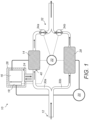
- FIG. 1 shows a schematic diagram of a water heating system 10 in accordance with an example of the invention.
- the water heating system 10 comprises a water inlet 12 configured to receive water from a water supply, such as a mains water supply or a water tank (not shown).
- the system 10 also includes an electrical heating device 14 for heating the water that enters the system 10 via the water inlet 12.
- the electrical heating device 14 may be an electrical resistive heating element for example.
- the electrical heating device 14 is electrically coupled to a battery 16 such that the battery 16 can power the electrical heating device 14.
- the electrical heating device 14 may be powered by direct current (DC) power supplied by the battery 16.
- the electrical heating device 14 may be an alternating current (AC) heating device 14, and the system 10 may further include a DC to AC converter (not shown) through which direct current power from the battery 16 may be converted to alternating current power for powering the heating device 14.
- DC direct current
- AC alternating current
- the water heating system 10 further includes a battery management system 18 electrically coupled to the battery 16 to enable charging of the battery 16, i.e. the battery management system 18 is configured to charge the battery 16.
- the battery management system 18 is preferably connected to the mains electricity 20 to receive electrical power for charging the battery 16.
- the water heating system 10 may also include an AC to DC power supply for the battery management system 18, which is configured to receive AC electricity from the mains supply 20, and convert this to DC electricity for charging the battery 16.
- the system 10 also includes a controller 22 that is operationally coupled to the battery management system 18 to control charging of the battery 16.
- the controller 22 may control charging of the battery 16 in dependence on at least one of, a charging status of the battery 16, a predicted cost of charging the battery 16, a current price of mains electricity, and a predicted demand for heated water. As such, the controller 22 may control the timing of charging the battery 16.
- the controller 22 may be configured to receive a user input to directly command charging the battery 16.
- the controller 22 is also coupled to the electrical heating device 14 to control operation of the heating device 14 in use.
- the heating device 14 may be electrically coupled to the mains electricity 20 such that the heating device 14 may be powered by the mains electricity 20 in addition to power provided by the battery 16.
- the system 10 may further comprise an AC to DC converter (not shown) such as a rectifier to rectify the AC mains electricity 20 to provide DC power to the heating device 14.
- the system 10 may therefore include a heating device 14 powered by both the battery 16 and the mains electricity 20.
- the heating device 14 may be powered primarily by the battery 16, with supplementary power provided by the mains electricity 20.
- the heating device 14 may be powered primarily by the mains electricity 20, and the battery 16 may provide supplementary power to achieve a heating performance comparable to that of a conventional gas boiler.
- the water heating system 10 includes a heat sink arrangement 24 that is specifically configured to store heat emitted from the battery 16 and other electrical components, and which therefore helps to regulate the temperature of the battery 16.
- the heat sink arrangement 24 is thermally coupled to the battery 16 to facilitate the transfer of heat energy from the battery 16 to the heat sink arrangement 24.
- the heat sink arrangement 24 is also thermally coupled to the battery management system 18 to receive heat from the battery management system 18.
- the water heating system 10 includes an AC to DC power supply for the battery management system 18, such an AC to DC power supply is preferably also thermally coupled to the heat sink arrangement 24 such that the heat sink arrangement 24 may receive and store heat energy emitted by the AC to DC power supply during charging of the battery 16.
- the heat sink arrangement 24 will be described in more detail later with reference to Figures 5 , 6 and particularly the cross-sectional view of Figure 7 .
- the heat sink arrangement 24 is configured with a heat capacity that is sufficient to store all of the heat produced by charging the battery 16 without causing the battery 16 damage through excessive thermal cycling.
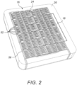
- the battery 16 and the heat sink arrangement 24 of the water heating system 10 are enclosed in a thermally insulating shell 26.
- the thermally insulating shell 26 also encloses the battery management system 18 as shown in Figure 2 .
- such a power supply is preferably also enclosed within the thermally insulating shell 26.
- the thermally insulating shell 26 ensures that heat produced by the battery 16 and other electrical components within the shell, and which is transferred to the heat sink arrangement 24, is retained in the heat sink arrangement 24, i.e. not wasted or immediately rejected.
- the water heating system 10 therefore advantageously facilitates effective use of the heat produced by the battery 16 to improve the overall efficiency and longevity of the water heating system 10 as will be described later in more detail.
- retaining the heat produced by the battery 16 enables pre-heating water before such water is delivered to the electrical heating device 14 as shown schematically in Figure 1 .
- Retaining the heat may also help to maintain the temperature of the battery 16 within an optimum operating range. Maximising the performance of the insulating shell 26, i.e. increasing the thermal resistance of the shell 26, increases the efficiency of the water heating system 10 by minimising the heat lost as a result of charging and discharging the battery 16.
- the insulating shell 26 is therefore configured to retain 70%, preferably at least 80%, or more preferably at least 90%, of the heat energy generated by charging and discharging the battery 16, in the heat sink arrangement 24 within the shell 26.
- the thermal performance of the shell 26 may be comparable to that of an insulated hot water tank.
- the water heating system 10 additionally includes a secondary heating device 28 as shown in the schematic diagram of Figure 1 .
- the secondary heating device 28 is preferably configured to be powered by mains electricity 20, and may for example comprise an electrical resistive heating element.
- the inclusion of a secondary heating device 28 facilitates an increased total heating power output, such that the heating power of the electrical water heating system 10 may be comparable to the heating power of a typical gas-powered boiler when both of the heating devices 14, 28, powered respectively by the battery 16 and mains 20, are used to heat water.
- the electrical heating device 14 and the secondary heating device 28 are provided on parallel fluid flow paths 30a, 30b.
- the electrical heating device 14 may be arranged on a first fluid flow path 30a
- the secondary heating device 28 may be arranged on a second fluid flow path 30b.
- the water heating system 10 may include a controllable valve arrangement 32 for controlling a fluid flow rate in each of the parallel fluid flow paths 30a, 30b.
- the system 10 may comprise a first controllable valve 34a arranged on the first fluid flow path 30a, and a second controllable valve 34b arranged on the second fluid flow path 30b.
- the water heating system 10 may be configured as an open system.
- the heat sink volume 36 is fluidly coupled to an inlet 40 of the electrical heating device 14.
- the heat sink volume 36 is in fluid communication with the inlet 40 of the electrical heating device 14 such that fluid 38 from the heat sink volume 36 is delivered to the electrical heating device 14 for subsequent additional heating.
- the heat exchange fluid 38 in the heat sink volume 36 may therefore be water that is introduced to the water heating system 10 via the main water inlet 12.
- the water flows from the water inlet 12, through the heat sink volume 36 and is then delivered to the electrical heating device 14, for example via the first fluid flow path 30a.
- water is pre-heated by the heat emitted from the battery 16, battery management system 18 and other electrical components housed in the insulating shell 26 before being heated further by the electrical heating device 14.
- Such a configuration provides an energy efficient water heating system 10 because surplus heat is transferred directly from the battery 16, battery management system 18, and other electrical components such as an AC to DC power supply, to the water to be heated. As such, energy input into the water heating system 10 is used either directly or indirectly for heating water, and is therefore not wasted.
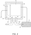
- FIG. 3 An inlet 42 and an outlet 44 of the heat sink volume 36 in an open system are shown schematically in Figure 3 .
- all of the water conveyed via the first fluid flow path 30a flows through the heat sink volume 36 first, before arriving at the electrical heating device 14.
- the system 10 may be configured such that a portion of the water flowing in the first fluid flow path 30a is diverted to flow through the heat sink volume 36, whilst the remaining water in the first fluid flow path 30a bypasses the heat sink volume 36 and is delivered directly to the electrical heating device 14.
- the water heating system 10 may comprise a release valve (not shown) fluidly coupled to the heat sink volume 36.
- the release valve may be configured to allow drainage of heat exchange fluid 38, such as water, from the heat sink volume 36. For example water may be released into the first fluid flow path 30a.
- the system 10 may also include a temperature sensor configured to measure the temperature inside the thermally insulating shell 26.
- the controller 22 is preferably operationally coupled to the temperature sensor and the release valve so that the release valve may be operated in dependence on the temperature inside the thermally insulating shell 26.
- the previously-described first controllable valve 34a may perform the same function as the release valve, i.e.
- the first controllable valve 34a may be opened or closed dependent on the temperature within the thermally insulating shell 26.
- the valve 34a may be operated independently from the electrical heating device 14, i.e. the valve 34a may be operated regardless of whether the electrical heating device 14 is operating to heat the water.
- the temperature inside the insulating shell 26 may be controlled by allowing or blocking the flow of water through the heat sink volume 36 by opening or closing the controllable valve 34a to allow or block the rejection of heat from the heat sink volume 36.
- a closed system is configured such that heat is removed from the interior of the insulating shell 26 via a heat exchanger 48.
- Figure 4 shows an example of a portion of a closed system at an interface between the heat sink volume 36 and a fluid flow path 30a. This configuration may be described as a closed system because the heat sink volume 36 is not in fluid communication with the first or second fluid flow path 30a, 30b.
- the heat exchanger 48 facilitates a transfer of heat energy from inside the insulating shell 26 to water flowing to an inlet 40 of the electrical heating device 14.
- the heat exchanger 48 is therefore preferably arranged upstream of the electrical heating device 14. As such, water delivered to the electrical heating device 14 may be pre-heated by the heat exchanger 48 using heat from within the insulating shell 26.
- a separate heat exchange fluid 38 is circulated within the heat sink volume 36 to receive heat energy emitted by the battery 16.
- the heat exchanger 48 is preferably configured to transfer heat from the heat exchange fluid 38 to water flowing to an inlet 40 of the electrical heating device 14.
- the heat exchange fluid 38 in the heat sink volume 36 of a closed system may be water.
- a closed system also facilitates the use of other heat exchange fluids 38, because in such a system, the heat exchange fluid 38 is not fluidly coupled to an outlet at which heated water is delivered to a consumer. Therefore, the heat exchange fluid 38 does not need to be safe for human consumption, and may include advantageous additives, such as an anti-corrosion agent for example.
- the heat sink volume 36 may be a complex configuration comprising a plurality of heat exchange fluid channels 50 (as shown in Figures 6 an d 7 for example). It may therefore be advantageous to configure the heat sink volume 36 as a closed system to allow close control of the fluid 38 within the heat sink volume 36.
- mains water may comprise different natural minerals that could leave deposits, such as limescale, on surfaces over which such water flows over time.
- a closed system heat sink volume 36 means that specific chemical agents can be introduced into the heat sink volume 36 to ensure that heat exchange fluid channels 50 do not become damaged, restricted or blocked by such deposits.
- water flowed over and around the battery 16 and other materials within the insulating shell 26 may not be suitable or safe for human consumption, and providing the heat sink volume 36 as a closed system therefore avoids any potential contamination of the water supplied to a consumer at an outlet.
- a closed system may include a pump (not shown) for circulating the heat exchange fluid 38 through the heat sink volume 36.
- a closed system may also include a temperature sensor (not shown) inside the thermally insulating shell 26.
- the controller 22 may be operationally coupled to the temperature sensor and the pump, and the controller 22 may operate the circulation pump in dependence on the temperature inside the insulating shell 26 to promote rejection of heat from the heat exchange fluid 38 to the incoming cold water flow in a fluid flow path 30a, 30b via the heat exchanger 48.
- a closed system may additionally include a release valve (not shown).
- the release valve may be fluidly coupled to the heat sink volume 36.
- the controller 22 may be operationally coupled to such a release valve such that the release valve may be operated in dependence on the temperature inside the insulating shell 26.
- a gaseous heat exchange fluid 38 such as air
- a liquid heat exchange fluid 38 may be released from the heat sink volume 36 via the release valve into a drain, for example, to control the temperature within the insulating shell 26.
- the release valve may be fluidly coupled to a fluid-based heating system, such as a water-based central heating system, such that, through operation of the release valve, heat may be rejected from the heat sink volume 36 to the fluid in the heating system.
- a fluid-based heating system such as a water-based central heating system
- Such rejection of heat may be facilitated simply by fluidly and thermally coupling the heat sink volume 36 with the heating system by opening the release valve, without necessarily requiring the heating system to be actively flowing heat exchange fluid 38 through the heat sink volume 36.
- Providing fluid communication between the heat sink volume 36 and a water-based heating system may increase the heat capacity available for storing heat emitted by the battery 16.
- the system 10 may also include a battery heating device that is enclosed in the thermally insulating shell 26.
- the battery heating device may be operationally coupled to the controller 22 such that the controller 22 can, when required, increase the temperature within the insulating shell 26 by operating the battery heating device to ensure that the temperature of the battery 16 remains within an optimum operating range.
- the fluid 38 in the heat sink volume 36 is referred to herein as a heat exchange fluid 38 because heat is transferred, i.e. exchanged, from the battery 16 to the heat exchange fluid 38.
- the heat exchange fluid 38 is the water to be heated using the heating device 14
- the heat exchange fluid 38 is a separate fluid to the water that is to be heated using the heating device 14.
- the battery 16 preferably comprises multiple battery modules 52.
- the battery modules 52 may each include one or more battery cells 54, such as chemical battery cells 54 for example.
- the battery modules 52 may be electrically connected to one another in series to provide a high current to the electrical heating device 14.
- the battery modules 52 may be electrically connected to one another in parallel such that high voltage power is provided to the electrical heating device 14.
- the electrical connections between the battery modules 52 may be selectively reconfigurable to facilitate active control of the current and voltage provided to the electrical heating device 14.
- the heat sink arrangement 24 includes a frame 56 that has multiple compartments or fixings which are arranged for holding one or more of the battery modules 52. It will be appreciated that, being part of the battery structure, the frame 56 is also housed inside the insulating shell 26 (as shown in Figure 2 for example). Therefore, the frame 56 provides additional heat capacity for storing heat energy emitted by the battery 16 and other electrical components within the shell 26. In some examples, and as shown most clearly in Figure 7 , the heat sink arrangement 24 within the insulating shell 26 may include a phase change material 60, and the phase change material 60 may be contained by the frame 56.
- the heat sink volume 36 comprises heat exchange fluid channels 50 that pass between or through respective battery modules 52.
- This configuration provides the heat sink volume 36 with a high surface area via which heat can be transferred to the heat exchange fluid 38.
- heat exchange fluid channels 50 of the heat sink volume 36 are also shown in the examples in Figures 5 and 6 .
- the following example assumes a charge efficiency of 90% and a battery capacity of 10 kWh.
- each cell 54 has a mass of 0.65 kg, a nominal voltage of 3.2 V, a capacity of 30 Ah, and provides an energy storage of 96 Wh.
- the specific heat capacity of such a cell 54 depends on the cell's precise construction however, it would typically be in the region of 0.8-1.7 kJ/kgK.
- each cell 54 has a specific heat capacity of 1 kJ/kgK.
- the water heating system 10 of the present invention therefore additionally includes a heat sink arrangement 24 within the insulating shell 26 to increase the heat capacity within the shell 26.
- the heat sink arrangement 24 within the insulating shell 26 includes the frame 56 for storing or mounting the battery modules 52 to hold them in position.
- the frame 56 may be made from cast aluminium.
- the frame 56 is configured to hold twelve of the previously-described cells 54 (for example, see Figure 6 ). It will be appreciated that any calculation can be conducted with an arbitrary number of cells as long as respective numbers are observed. In doing so, temperature change can be directly compared.
- the temperature increase experienced by the cells as a result of the heat emitted during charging, without use of a heat sink 24 within the shell 26, would therefore be 460.8 kJ / 7.8 kJ/K 59°C in this example.
- the frame 56 inside the insulating shell 26 is part of the heat sink 24 in this example.
- the frame 56 may be assumed to have a mass of 2.5 kg, and the specific heat capacity of aluminium is 0.96 kJ/kgK.
- the twelve cells 54 in this example have a storage capacity of 1.152 kWh, and the heat energy emitted during charging at 90% efficiency is 460.8 kJ.
- Providing a heat sink arrangement 24 that includes the frame 56 therefore reduces the temperature increase experienced by the cells 54 within the insulating shell 26 during charging.
- the heat capacity within the shell 26 is further increased by including heat exchange fluid 38 in the heat sink volume 36 within the insulating shell 26.
- the heat exchange fluid 38 is water.
- the heat sink volume 36 i.e. including the heat exchange fluid channels 50, may have a volume of 0.466 litres in this example.
- the total heat emitted during charging at 90% efficiency is 460.8kJ.
- the heat exchange fluid 38 within the heat sink volume 36 therefore further reduces the temperature increase.
- the water heating system 10 may additionally include a phase change material 60, such as sodium sulphate, within the insulating shell 26.
- a phase change material 60 such as sodium sulphate
- the phase change material 60 is sodium sulphate which has a melting point of 32.4°C and a heat of fusion of 252 kJ/kg. Accordingly, 252kJ of energy are required to melt 1kg of sodium sulphate, and this will occur at 32.4°C.
- the water heating system 10 is configured such that the melting point of the phase change material 60 is within the range of temperatures experienced inside the insulating shell 26 when charging and discharging the battery 16. As such, the change in temperature will pause for the duration of time taken to melt (or freeze) a given volume of the phase change material 60.
- three of the nine heat exchange fluid channels 50 in the frame 56 shown by way of example in Figure 6 may be filled with sodium sulphate 60. That is to say the sodium sulphate, i.e. phase change material 60, may be housed in the heat sink arrangement 24 in a compartment provided by the frame 56.
- the energy required to melt this volume of phase change material 60 can be subtracted from the energy available to increase the temperature (or added to the energy rejected when cooling).
- the heat exchange fluid channels 50 filled with heat exchange fluid 38 now have a volume of 0.311 litres, and the system 10 therefore comprises water with a mass of 0.311 kg in the heat sink volume 36.
- phase change material 60 within the shell 26 therefore further reduces the increase in temperature experienced by the cells 54 which increases their longevity as previously described.
- the invention described herein and defined in the appended claims advantageously stores heat emitted by the battery 16 during charging and utilises it to enable more efficient water heating and increase battery longevity.
- Increasing the efficiency of a system typically results in an increase in materials and manufacturing costs.
- the water heating system 10 of the present invention facilitates an increased system efficiency without increasing cost.
- less efficient cells 54 with higher internal resistance resulting in a greater heat output can be used because the emitted heat is recaptured in the heat sink arrangement 24 for later use.
- Use of such cells 54 is likely to carry a cost advantage.
- the electronics in the battery management system 18 can be deliberately designed to be less optimal, and therefore cheaper, because the heat energy emitted is captured and stored for later use.
Landscapes
- Engineering & Computer Science (AREA)
- Chemical & Material Sciences (AREA)
- General Chemical & Material Sciences (AREA)
- Chemical Kinetics & Catalysis (AREA)
- Electrochemistry (AREA)
- Manufacturing & Machinery (AREA)
- Thermal Sciences (AREA)
- Physics & Mathematics (AREA)
- Mechanical Engineering (AREA)
- General Engineering & Computer Science (AREA)
- Combustion & Propulsion (AREA)
- Microelectronics & Electronic Packaging (AREA)
- Automation & Control Theory (AREA)
- Heat-Pump Type And Storage Water Heaters (AREA)
- Instantaneous Water Boilers, Portable Hot-Water Supply Apparatuses, And Control Of Portable Hot-Water Supply Apparatuses (AREA)
- Secondary Cells (AREA)
Claims (19)
- Wasserheizungssystem (10), das Folgendes umfasst:- ein Außengehäuse,- eine elektrische Heizungsvorrichtung (14) zum Erhitzen von Wasser,- eine Batterie (16), die mit der elektrischen Heizungsvorrichtung zum Stromversorgen der elektrischen Heizungsvorrichtung elektrisch gekoppelt ist,- ein Batteriemanagementsystem (18), das mit der Batterie zum Laden der Batterie elektrisch gekoppelt ist,- eine Wärmesenkenanordnung (24), die mit der Batterie thermisch gekoppelt ist und dazu konfiguriert ist, thermische Energie zu speichern und freizugeben, und- einen thermisch isolierenden Mantel (26), der innerhalb des Außengehäuses untergebracht ist, dadurch gekennzeichnet, dass der thermisch isolierende Mantel die Batterie und die Wärmesenkenanordnung einschließt.
- Wasserheizungssystem (10) gemäß Anspruch 1, wobei die Wärmesenkenanordnung (24) eine Wärmekapazität aufweist, die ausreicht, um sämtliche Wärme, die durch das Laden der Batterie (16) produziert wird, zu speichern, ohne an der Batterie einen Schaden durch übermäßiges thermisches Wechselbeanspruchen zu verursachen.
- Wasserheizungssystem (10) gemäß Anspruch 1 oder 2, wobei die Wärmesenkenanordnung (24) mit dem Batteriemanagementsystem (18) thermisch gekoppelt ist und wobei der thermisch isolierende Mantel (26) ferner das Batteriemanagementsystem einschließt.
- Wasserheizungssystem (10) gemäß einem vorhergehenden Anspruch, wobei die Wärmesenkenanordnung (24) einen Wärmetauscher (48) umfasst, der dazu konfiguriert ist, einen Wärmetausch zwischen einem Inneren des isolierenden Mantels (26) und Wasser, das zu einem Einlass (40) der elektrischen Heizungsvorrichtung (14) fließt, zu erleichtern.
- Wasserheizungssystem (10) gemäß einem vorhergehenden Anspruch, wobei die Wärmesenkenanordnung (24) ein Wärmesenkenvolumen (36) zum Halten eines Wärmetauschfluids (38) umfasst.
- Wasserheizungssystem (10) gemäß Anspruch 5, wobei das Wärmesenkenvolumen (36) mit einem Einlass (40) der elektrischen Heizungsvorrichtung (14) fluidisch gekoppelt ist.
- Wasserheizungssystem (10) gemäß Anspruch 5 oder 6, wobei die Wärmesenkenanordnung (24) einen Wärmetauscher (48) zum Tauschen von Wärme zwischen einem Wärmetauschfluid (38) in dem Wärmesenkenvolumen (36) und Wasser, das zu einem Einlass (40) der elektrischen Heizungsvorrichtung (14) fließt, umfasst.
- Wasserheizungssystem (10) gemäß Anspruch 7, das ferner eine Pumpe zum Zirkulieren des Wärmetauschfluids (38) durch das Wärmesenkenvolumen (36) umfasst.
- Wasserheizungssystem (10) gemäß einem der Ansprüche 5 bis 8, das ferner Folgendes umfasst: eine Steuereinheit (22), die mit dem Batteriemanagementsystem (18) und/oder der elektrischen Heizungsvorrichtung (14) betriebsmäßig gekoppelt ist, und einen Temperatursensor zum Messen einer Temperatur in dem thermisch isolierenden Mantel (26), wobei die Steuereinheit mit einer Vorrichtung betriebsmäßig gekoppelt ist, die dazu konfiguriert ist, einen Fluss innerhalb des Wärmesenkenvolumens (36) zu initiieren, wie etwa eine Pumpe oder ein Freigabeventil, die/das mit dem Wärmesenkenvolumen fluidisch gekoppelt ist, wobei die Steuereinheit mit dem Temperatursensor und der Vorrichtung betriebsmäßig gekoppelt ist und dazu konfiguriert ist, einen Fluss innerhalb des Wärmesenkenvolumens selektiv zu initiieren, um Wärme von dem Wärmesenkenvolumen in Abhängigkeit von der Temperatur in dem thermisch isolierenden Mantel abzuweisen.
- Wasserheizungssystem (10) gemäß Anspruch 9, das ferner ein Freigabeventil umfasst, das mit dem Wärmesenkenvolumen fluidisch gekoppelt ist und dazu konfiguriert ist, die Freigabe von Wärmetauschfluid (38) von dem Wärmesenkenvolumen (36) zu erleichtern, wobei die Steuereinheit (22) mit dem Temperatursensor und dem Freigabeventil betriebsmäßig gekoppelt ist und dazu konfiguriert ist, das Freigabeventil in Abhängigkeit von der Temperatur in dem thermisch isolierenden Mantel (26) zu öffnen.
- Wasserheizungssystem (10) gemäß Anspruch 10, wobei das Freigabeventil zusätzlich mit einem Einlass (40) der elektrischen Heizungsvorrichtung (14) fluidisch gekoppelt ist und dazu konfiguriert ist, eine Ableitung von Wasser von dem Wärmesenkenvolumen (36) in den Einlass der elektrischen Heizungsvorrichtung zu erlauben.
- Wasserheizungssystem (10) gemäß Anspruch 9 und umfassend eine Pumpe zum Zirkulieren des Wärmetauschfluids (38) durch das Wärmesenkenvolumen (36), wobei die Steuereinheit (22) mit dem Temperatursensor und der Pumpe betriebsmäßig gekoppelt ist und dazu konfiguriert ist, die Pumpe in Abhängigkeit von der Temperatur in dem thermisch isolierenden Mantel (26) zu betreiben.
- Wasserheizungssystem (10) gemäß einem vorhergehenden Anspruch, das ferner eine sekundäre Heizungsvorrichtung (28) umfasst, die dazu konfiguriert ist, mit Netzelektrizität versorgt zu werden.
- Wasserheizungssystem (10) gemäß Anspruch 13, wobei die elektrische Heizungsvorrichtung (14) und die sekundäre Heizungsvorrichtung (28) auf parallelen Fluidflusspfaden (30a, 30b) bereitgestellt sind, wobei das Wasserheizungssystem ferner eine steuerbare Ventilanordnung (32) zum Steuern einer Fluidflussrate in jedem der parallelen Fluidflusspfade umfasst.
- Wasserheizungssystem (10) gemäß einem vorhergehenden Anspruch, wobei die Wärmesenkenanordnung (24) ein Phasenwechselmaterial (60) beinhaltet.
- Wasserheizungssystem (10) gemäß einem vorhergehenden Anspruch, wobei die Batterie (16) mehrere Module (52) umfasst, die jeweils eine oder mehrere individuelle Zellen (54) enthalten, und wobei die Wärmesenkenanordnung (24) einen Rahmen (56) mit mehreren Kammern (58) oder Fixierungen umfasst, wobei jede Kammer oder Fixierung zum Halten eines oder mehrerer der Batteriemodule angeordnet ist.
- Wasserheizungssystem (10) gemäß Anspruch 16, wobei die Wärmesenkenanordnung (24) ein Wärmesenkenvolumen (36) zum Halten eines Wärmetauschfluids (38) umfasst und wobei das Wärmesenkenvolumen Wärmetauschfluidkanäle (50) umfasst, die zwischen und/oder durch jeweilige Batteriemodule (52) verlaufen.
- Wasserheizungssystem (10) gemäß einem vorhergehenden Anspruch, das ferner eine Batterieheizungsvorrichtung umfasst, die in dem thermisch isolierenden Mantel (26) eingeschlossen ist.
- Wasserheizungssystem (10) gemäß einem vorhergehenden Anspruch, das ferner eine AC-zu-DC-Stromversorgung in dem isolierenden Mantel (26) umfasst, wobei die Stromversorgung mit mindestens einem von der Batterie (16) und/oder dem Batteriemanagementsystem (18) elektrisch gekoppelt ist, um die Batterie mit Strom zu versorgen, und die Stromversorgung mit der Wärmesenkenanordnung (24) thermisch gekoppelt ist.
Applications Claiming Priority (2)
| Application Number | Priority Date | Filing Date | Title |
|---|---|---|---|
| GB2201082.1A GB2615102B (en) | 2022-01-27 | 2022-01-27 | Water heating system |
| PCT/GB2023/050193 WO2023144557A1 (en) | 2022-01-27 | 2023-01-27 | Water heating system |
Publications (3)
| Publication Number | Publication Date |
|---|---|
| EP4409205A1 EP4409205A1 (de) | 2024-08-07 |
| EP4409205B1 true EP4409205B1 (de) | 2025-05-07 |
| EP4409205C0 EP4409205C0 (de) | 2025-05-07 |
Family
ID=80621178
Family Applications (1)
| Application Number | Title | Priority Date | Filing Date |
|---|---|---|---|
| EP23707441.4A Active EP4409205B1 (de) | 2022-01-27 | 2023-01-27 | Wasserheizungsanlage |
Country Status (11)
| Country | Link |
|---|---|
| US (1) | US20250257904A1 (de) |
| EP (1) | EP4409205B1 (de) |
| JP (1) | JP2025503300A (de) |
| KR (1) | KR20240156602A (de) |
| CN (1) | CN119032242A (de) |
| AU (1) | AU2023211879A1 (de) |
| CA (1) | CA3249975A1 (de) |
| ES (1) | ES3037497T3 (de) |
| GB (1) | GB2615102B (de) |
| PL (1) | PL4409205T3 (de) |
| WO (1) | WO2023144557A1 (de) |
Families Citing this family (1)
| Publication number | Priority date | Publication date | Assignee | Title |
|---|---|---|---|---|
| US20250362033A1 (en) * | 2024-05-23 | 2025-11-27 | Caterpillar Inc. | Co-generation system for heating application |
Citations (1)
| Publication number | Priority date | Publication date | Assignee | Title |
|---|---|---|---|---|
| WO2012004985A1 (ja) * | 2010-07-07 | 2012-01-12 | パナソニック株式会社 | 貯湯式給湯システムとその運転方法 |
Family Cites Families (10)
| Publication number | Priority date | Publication date | Assignee | Title |
|---|---|---|---|---|
| US4363221A (en) * | 1979-08-20 | 1982-12-14 | Singh Kanwal N | Water heating system having a heat pump |
| JP5012695B2 (ja) * | 2008-06-26 | 2012-08-29 | 株式会社デンソー | 給湯システム |
| DE102009030999A1 (de) | 2008-07-07 | 2010-04-08 | Denso Corporation, Kariya-City | Heißwasser-Versorgungssystem |
| JP4631967B2 (ja) * | 2008-12-22 | 2011-02-16 | 株式会社デンソー | 蓄電蓄熱装置 |
| JP6344015B2 (ja) * | 2014-03-31 | 2018-06-20 | ダイキン工業株式会社 | 給湯システム |
| KR102394801B1 (ko) * | 2017-10-20 | 2022-05-04 | 현대자동차주식회사 | 차량용 배터리 냉각 장치 |
| KR101990592B1 (ko) * | 2018-05-28 | 2019-06-18 | 한국기계연구원 | 상변화 냉각모듈 및 이를 이용하는 배터리팩 |
| KR102096616B1 (ko) * | 2018-07-24 | 2020-04-02 | 광운대학교 산학협력단 | 계통 연계 및 독립형으로 운전이 가능한 소규모 태양광/태양열 융복합 시스템 |
| CN111829165A (zh) * | 2019-04-20 | 2020-10-27 | 青岛经济技术开发区海尔热水器有限公司 | 壁挂式外壳及电热水器 |
| CN110440334A (zh) * | 2019-09-05 | 2019-11-12 | 上海建筑设计研究院有限公司 | 一种生活热水供给系统 |
-
2022
- 2022-01-27 GB GB2201082.1A patent/GB2615102B/en active Active
-
2023
- 2023-01-27 KR KR1020247028738A patent/KR20240156602A/ko active Pending
- 2023-01-27 AU AU2023211879A patent/AU2023211879A1/en active Pending
- 2023-01-27 JP JP2024545257A patent/JP2025503300A/ja active Pending
- 2023-01-27 US US18/833,360 patent/US20250257904A1/en active Pending
- 2023-01-27 CN CN202380029120.1A patent/CN119032242A/zh active Pending
- 2023-01-27 EP EP23707441.4A patent/EP4409205B1/de active Active
- 2023-01-27 CA CA3249975A patent/CA3249975A1/en active Pending
- 2023-01-27 WO PCT/GB2023/050193 patent/WO2023144557A1/en not_active Ceased
- 2023-01-27 ES ES23707441T patent/ES3037497T3/es active Active
- 2023-01-27 PL PL23707441.4T patent/PL4409205T3/pl unknown
Patent Citations (1)
| Publication number | Priority date | Publication date | Assignee | Title |
|---|---|---|---|---|
| WO2012004985A1 (ja) * | 2010-07-07 | 2012-01-12 | パナソニック株式会社 | 貯湯式給湯システムとその運転方法 |
Also Published As
| Publication number | Publication date |
|---|---|
| WO2023144557A1 (en) | 2023-08-03 |
| CA3249975A1 (en) | 2023-08-03 |
| ES3037497T3 (en) | 2025-10-02 |
| GB2615102A (en) | 2023-08-02 |
| EP4409205C0 (de) | 2025-05-07 |
| GB2615102B (en) | 2024-01-10 |
| CN119032242A (zh) | 2024-11-26 |
| JP2025503300A (ja) | 2025-01-30 |
| EP4409205A1 (de) | 2024-08-07 |
| KR20240156602A (ko) | 2024-10-30 |
| US20250257904A1 (en) | 2025-08-14 |
| GB202201082D0 (en) | 2022-03-16 |
| AU2023211879A1 (en) | 2024-09-05 |
| PL4409205T3 (pl) | 2025-09-22 |
Similar Documents
| Publication | Publication Date | Title |
|---|---|---|
| CN102741617B (zh) | 加热系统 | |
| CN206929835U (zh) | 可调节的熔盐储热系统 | |
| EP4409205B1 (de) | Wasserheizungsanlage | |
| DK2795199T3 (en) | Heat Supply System and heat supply process | |
| US20240337417A1 (en) | Electric fluid heater | |
| CN109099502A (zh) | 相变蓄热式电热蒸汽与热水供应系统及其控制方法 | |
| US20100263606A1 (en) | Thermal store | |
| US12111078B2 (en) | Heating system | |
| HK40119500A (zh) | 水加热系统 | |
| CN209279238U (zh) | 相变蓄热式电热蒸汽与热水供应系统 | |
| US20250297771A1 (en) | Electric fluid heater | |
| JP7574461B2 (ja) | 家庭用温水またはセントラルヒーティングのための熱を生成するシステム | |
| EP4545867A1 (de) | Vorrichtung zum austausch von wärmeenergie zwischen einer wärmequelle und einem zweiten medium sowie verfahren zum betreiben einer solchen vorrichtung | |
| HK40111983A (zh) | 电流体加热器 | |
| JP2003047155A (ja) | 給電方法 | |
| CN120332812A (zh) | 一种模块化电极加热熔盐的蓄热释热装置 | |
| EP2406837A2 (de) | Verbrennungssystem zur erzeugung von wärme und strom | |
| GB2615282A (en) | Electric fluid heater | |
| HK40118227A (en) | Heat pump system | |
| KR20250175005A (ko) | 히트 펌프 시스템 |
Legal Events
| Date | Code | Title | Description |
|---|---|---|---|
| STAA | Information on the status of an ep patent application or granted ep patent |
Free format text: STATUS: UNKNOWN |
|
| STAA | Information on the status of an ep patent application or granted ep patent |
Free format text: STATUS: THE INTERNATIONAL PUBLICATION HAS BEEN MADE |
|
| STAA | Information on the status of an ep patent application or granted ep patent |
Free format text: STATUS: EXAMINATION IS IN PROGRESS |
|
| PUAI | Public reference made under article 153(3) epc to a published international application that has entered the european phase |
Free format text: ORIGINAL CODE: 0009012 |
|
| 17P | Request for examination filed |
Effective date: 20240502 |
|
| AK | Designated contracting states |
Kind code of ref document: A1 Designated state(s): AL AT BE BG CH CY CZ DE DK EE ES FI FR GB GR HR HU IE IS IT LI LT LU LV MC ME MK MT NL NO PL PT RO RS SE SI SK SM TR |
|
| GRAP | Despatch of communication of intention to grant a patent |
Free format text: ORIGINAL CODE: EPIDOSNIGR1 |
|
| STAA | Information on the status of an ep patent application or granted ep patent |
Free format text: STATUS: GRANT OF PATENT IS INTENDED |
|
| DAV | Request for validation of the european patent (deleted) | ||
| DAX | Request for extension of the european patent (deleted) | ||
| INTG | Intention to grant announced |
Effective date: 20241212 |
|
| GRAS | Grant fee paid |
Free format text: ORIGINAL CODE: EPIDOSNIGR3 |
|
| GRAA | (expected) grant |
Free format text: ORIGINAL CODE: 0009210 |
|
| STAA | Information on the status of an ep patent application or granted ep patent |
Free format text: STATUS: THE PATENT HAS BEEN GRANTED |
|
| AK | Designated contracting states |
Kind code of ref document: B1 Designated state(s): AL AT BE BG CH CY CZ DE DK EE ES FI FR GB GR HR HU IE IS IT LI LT LU LV MC ME MK MT NL NO PL PT RO RS SE SI SK SM TR |
|
| REG | Reference to a national code |
Ref country code: GB Ref legal event code: FG4D |
|
| REG | Reference to a national code |
Ref country code: CH Ref legal event code: EP |
|
| REG | Reference to a national code |
Ref country code: DE Ref legal event code: R096 Ref document number: 602023003374 Country of ref document: DE |
|
| REG | Reference to a national code |
Ref country code: IE Ref legal event code: FG4D |
|
| U01 | Request for unitary effect filed |
Effective date: 20250605 |
|
| U07 | Unitary effect registered |
Designated state(s): AT BE BG DE DK EE FI FR IT LT LU LV MT NL PT RO SE SI Effective date: 20250613 |
|
| RAP4 | Party data changed (patent owner data changed or rights of a patent transferred) |
Owner name: LUTHMORE LTD |
|
| U1H | Name or address of the proprietor changed after the registration of the unitary effect |
Owner name: LUTHMORE LTD; GB |
|
| REG | Reference to a national code |
Ref country code: ES Ref legal event code: FG2A Ref document number: 3037497 Country of ref document: ES Kind code of ref document: T3 Effective date: 20251002 |
|
| REG | Reference to a national code |
Ref country code: SK Ref legal event code: T3 Ref document number: E 46885 Country of ref document: SK |
|
| PG25 | Lapsed in a contracting state [announced via postgrant information from national office to epo] |
Ref country code: HR Free format text: LAPSE BECAUSE OF FAILURE TO SUBMIT A TRANSLATION OF THE DESCRIPTION OR TO PAY THE FEE WITHIN THE PRESCRIBED TIME-LIMIT Effective date: 20250507 |
|
| PG25 | Lapsed in a contracting state [announced via postgrant information from national office to epo] |
Ref country code: RS Free format text: LAPSE BECAUSE OF FAILURE TO SUBMIT A TRANSLATION OF THE DESCRIPTION OR TO PAY THE FEE WITHIN THE PRESCRIBED TIME-LIMIT Effective date: 20250807 |
|
| PG25 | Lapsed in a contracting state [announced via postgrant information from national office to epo] |
Ref country code: IS Free format text: LAPSE BECAUSE OF FAILURE TO SUBMIT A TRANSLATION OF THE DESCRIPTION OR TO PAY THE FEE WITHIN THE PRESCRIBED TIME-LIMIT Effective date: 20250907 |
|
| PG25 | Lapsed in a contracting state [announced via postgrant information from national office to epo] |
Ref country code: SM Free format text: LAPSE BECAUSE OF FAILURE TO SUBMIT A TRANSLATION OF THE DESCRIPTION OR TO PAY THE FEE WITHIN THE PRESCRIBED TIME-LIMIT Effective date: 20250507 |
|
| REG | Reference to a national code |
Ref country code: CH Ref legal event code: U11 Free format text: ST27 STATUS EVENT CODE: U-0-0-U10-U11 (AS PROVIDED BY THE NATIONAL OFFICE) Effective date: 20260201 |
|
| U20 | Renewal fee for the european patent with unitary effect paid |
Year of fee payment: 4 Effective date: 20260106 |
|
| PLBE | No opposition filed within time limit |
Free format text: ORIGINAL CODE: 0009261 |
|
| STAA | Information on the status of an ep patent application or granted ep patent |
Free format text: STATUS: NO OPPOSITION FILED WITHIN TIME LIMIT |
|
| REG | Reference to a national code |
Ref country code: CH Ref legal event code: L10 Free format text: ST27 STATUS EVENT CODE: U-0-0-L10-L00 (AS PROVIDED BY THE NATIONAL OFFICE) Effective date: 20260318 |