EP4407979A1 - Verfahren und vorrichtung zur einstellung der geschwindigkeit eines multimedia-clips, vorrichtung und medium - Google Patents
Verfahren und vorrichtung zur einstellung der geschwindigkeit eines multimedia-clips, vorrichtung und medium Download PDFInfo
- Publication number
- EP4407979A1 EP4407979A1 EP23815243.3A EP23815243A EP4407979A1 EP 4407979 A1 EP4407979 A1 EP 4407979A1 EP 23815243 A EP23815243 A EP 23815243A EP 4407979 A1 EP4407979 A1 EP 4407979A1
- Authority
- EP
- European Patent Office
- Prior art keywords
- speed
- target interval
- control point
- interval
- response
- Prior art date
- Legal status (The legal status is an assumption and is not a legal conclusion. Google has not performed a legal analysis and makes no representation as to the accuracy of the status listed.)
- Pending
Links
Images


Classifications
-
- H—ELECTRICITY
- H04—ELECTRIC COMMUNICATION TECHNIQUE
- H04N—PICTORIAL COMMUNICATION, e.g. TELEVISION
- H04N21/00—Selective content distribution, e.g. interactive television or video on demand [VOD]
- H04N21/40—Client devices specifically adapted for the reception of or interaction with content, e.g. set-top-box [STB]; Operations thereof
- H04N21/43—Processing of content or additional data, e.g. demultiplexing additional data from a digital video stream; Elementary client operations, e.g. monitoring of home network or synchronising decoder's clock; Client middleware
- H04N21/44—Processing of video elementary streams, e.g. splicing a video clip retrieved from local storage with an incoming video stream or rendering scenes according to encoded video stream scene graphs
- H04N21/4402—Processing of video elementary streams, e.g. splicing a video clip retrieved from local storage with an incoming video stream or rendering scenes according to encoded video stream scene graphs involving reformatting operations of video signals for household redistribution, storage or real-time display
-
- H—ELECTRICITY
- H04—ELECTRIC COMMUNICATION TECHNIQUE
- H04N—PICTORIAL COMMUNICATION, e.g. TELEVISION
- H04N7/00—Television systems
- H04N7/01—Conversion of standards, e.g. involving analogue television standards or digital television standards processed at pixel level
- H04N7/0127—Conversion of standards, e.g. involving analogue television standards or digital television standards processed at pixel level by changing the field or frame frequency of the incoming video signal, e.g. frame rate converter
-
- G—PHYSICS
- G11—INFORMATION STORAGE
- G11B—INFORMATION STORAGE BASED ON RELATIVE MOVEMENT BETWEEN RECORD CARRIER AND TRANSDUCER
- G11B27/00—Editing; Indexing; Addressing; Timing or synchronising; Monitoring; Measuring tape travel
- G11B27/005—Reproducing at a different information rate from the information rate of recording
-
- G—PHYSICS
- G11—INFORMATION STORAGE
- G11B—INFORMATION STORAGE BASED ON RELATIVE MOVEMENT BETWEEN RECORD CARRIER AND TRANSDUCER
- G11B27/00—Editing; Indexing; Addressing; Timing or synchronising; Monitoring; Measuring tape travel
- G11B27/02—Editing, e.g. varying the order of information signals recorded on, or reproduced from, record carriers
- G11B27/031—Electronic editing of digitised analogue information signals, e.g. audio or video signals
-
- G—PHYSICS
- G11—INFORMATION STORAGE
- G11B—INFORMATION STORAGE BASED ON RELATIVE MOVEMENT BETWEEN RECORD CARRIER AND TRANSDUCER
- G11B27/00—Editing; Indexing; Addressing; Timing or synchronising; Monitoring; Measuring tape travel
- G11B27/10—Indexing; Addressing; Timing or synchronising; Measuring tape travel
- G11B27/34—Indicating arrangements
-
- G—PHYSICS
- G11—INFORMATION STORAGE
- G11B—INFORMATION STORAGE BASED ON RELATIVE MOVEMENT BETWEEN RECORD CARRIER AND TRANSDUCER
- G11B27/00—Editing; Indexing; Addressing; Timing or synchronising; Monitoring; Measuring tape travel
- G11B27/36—Monitoring, i.e. supervising the progress of recording or reproducing
-
- H—ELECTRICITY
- H04—ELECTRIC COMMUNICATION TECHNIQUE
- H04N—PICTORIAL COMMUNICATION, e.g. TELEVISION
- H04N21/00—Selective content distribution, e.g. interactive television or video on demand [VOD]
- H04N21/40—Client devices specifically adapted for the reception of or interaction with content, e.g. set-top-box [STB]; Operations thereof
- H04N21/45—Management operations performed by the client for facilitating the reception of or the interaction with the content or administrating data related to the end-user or to the client device itself, e.g. learning user preferences for recommending movies, resolving scheduling conflicts
-
- H—ELECTRICITY
- H04—ELECTRIC COMMUNICATION TECHNIQUE
- H04N—PICTORIAL COMMUNICATION, e.g. TELEVISION
- H04N21/00—Selective content distribution, e.g. interactive television or video on demand [VOD]
- H04N21/40—Client devices specifically adapted for the reception of or interaction with content, e.g. set-top-box [STB]; Operations thereof
- H04N21/47—End-user applications
- H04N21/472—End-user interface for requesting content, additional data or services; End-user interface for interacting with content, e.g. for content reservation or setting reminders, for requesting event notification, for manipulating displayed content
- H04N21/47205—End-user interface for requesting content, additional data or services; End-user interface for interacting with content, e.g. for content reservation or setting reminders, for requesting event notification, for manipulating displayed content for manipulating displayed content, e.g. interacting with MPEG-4 objects, editing locally
-
- H—ELECTRICITY
- H04—ELECTRIC COMMUNICATION TECHNIQUE
- H04N—PICTORIAL COMMUNICATION, e.g. TELEVISION
- H04N5/00—Details of television systems
- H04N5/222—Studio circuitry; Studio devices; Studio equipment
- H04N5/262—Studio circuits, e.g. for mixing, switching-over, change of character of image, other special effects ; Cameras specially adapted for the electronic generation of special effects
-
- H—ELECTRICITY
- H04—ELECTRIC COMMUNICATION TECHNIQUE
- H04N—PICTORIAL COMMUNICATION, e.g. TELEVISION
- H04N5/00—Details of television systems
- H04N5/76—Television signal recording
- H04N5/78—Television signal recording using magnetic recording
- H04N5/782—Television signal recording using magnetic recording on tape
- H04N5/783—Adaptations for reproducing at a rate different from the recording rate
Definitions
- This disclosure relates to the technical field of video processing technology, in particular to a multimedia clip speed adjustment method, an apparatus, a device and a medium.
- conventional speed regulation comprises constant speed regulation and non-uniform speed regulation base on a curve. Users can select desired templates from speed regulation templates preset in applications according to their needs.
- An embodiment of the present disclosure provides a multimedia clip speed adjustment method, comprising: segmenting a multimedia material clip into multiple intervals on an editing track for an audio or a video, the multiple intervals comprising a target interval, wherein a first control point and a second control point corresponding to the target interval are provided on the multimedia material clip; adjusting, in response to a movement operation on the first control point, a speed change amount based on a position of the first control point on the editing track, controlling a speed of video frames within the target interval to change according to a speed change amount adjusted, and increasing or decreasing a displayed length of the target interval on the editing track according to a playback duration of the video frames of which the speed is changed; adjusting, in response to a movement operation on the second control point, a slope of a speed curve based on a position of the second control point within the target interval, and controlling the speed of the video frames within the target interval to change according to the speed curve with a slope adjusted.
- An embodiment of the present disclosure further provides an apparatus for adjusting the speed of a multimedia clip, comprising: a segmentation module for segmenting a multimedia material clip into multiple intervals on an editing track for an audio or a video, the multiple intervals comprising a target interval, wherein a first control point and a second control point corresponding to the target interval are provided on the multimedia material clip; a first speed change control module for adjusting, in response to a movement operation on the first control point, a speed change amount based on a position of the first control point on the editing track, controlling the speed of video frames within the target interval to vary according to the adjusted speed change amount, and increasing or decreasing a displayed length of the target interval on the editing track according to a playback duration of the speed-changed video frames; a second speed change control module for adjusting, in response to a movement operation on the second control point, a slope of a speed curve based on a position of the second control point within the target interval, and controlling the speed of the video frames within the target interval to vary according to the speed
- An embodiment of the present disclosure provides an electronic device, comprising: a processor; a memory for storing processor executable instructions; wherein the processor is used to read the executable instructions from the memory and execute the instructions to implement the multimedia clip speed adjustment method provided in the embodiments of the present disclosure.
- An embodiment of the present disclosure further discloses a computer readable storage medium having stored thereon a computer program, wherein the computer program is used to perform the multimedia clip speed adjustment method provided in the embodiments of the present disclosure.
- An embodiment of the present disclosure further provides a computer program, comprising: instructions that, when executed by a processor, cause the processor to implement the multimedia clip speed adjustment method provided in the embodiments of the present disclosure.
- the process of customized variable speed adjustment may involve adjusting a speed curve by dragging and dropping multiple control points on a control panel.
- the adjustment of a control point may cause changes occurred in those curve portions that are adjacent to the control point, resulting in low accuracy and poor efficiency in variable speed adjustment of audio and video clips.
- the embodiments of the present invention provides a multimedia clip speed adjustment method.
- a multimedia material is segmented into multiple intervals.
- the playback speed of video frames within these intervals can be adjusted independently, and an overall speed adjustment is made based on a first control point for video frames within each interval. It is also possible to achieve speed regulation based on a second control point to allow different playback speeds of different video frames within the same interval. As a result, fine speed adjustment can be achieved for the video frames, and the accuracy and efficiency of speed adjustment can be improved.
- the present disclosure provides a multimedia clip speed adjustment method, an apparatus, a device and a medium, which can achieve fine speed adjustment for video frames and improve the accuracy and efficiency of video frame speed adjustment.
- FIG. 1 is a flowchart of a multimedia clip speed adjustment method provided in embodiments of the present disclosure. This method can be performed by a multimedia clip speed adjustment apparatus, wherein the apparatus can be implemented by software and/or hardware, and can generally be integrated in an electronic device. As shown in FIG. 1 , the method comprises steps 101 to 103.
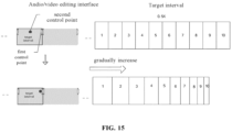
- a multimedia material clip is segmented into multiple intervals on an editing track for an audio or a video.
- the multiple intervals comprise a target interval, and a first control point and a second control point corresponding to the target interval are provided on the multimedia material clip.
- an editing track for an audio or a video can be displayed on a visualization interface.
- a video stream to be adjusted can be mapped to the audio or video editing track, with different intervals on the track corresponding to different video stream segments of the video stream.
- the display of the audio or video editing track can be called up by some shortcut keys, by triggering a preset control, or in other manners not listed herein.
- a multimedia material is segmented into different intervals on the audio or video editing track.
- the initial playback speed of the video frames within an interval can be the playback speed of the video stream before segmentation.
- a preset video threshold can be calibrated based on experimental data, for example, the preset threshold can be 3. If the number of video frames detected is less than the video threshold, an inappropriate segmentation prompt is displayed, for example, a pop-up window displaying a message such as "Too small intervals are not allowed".
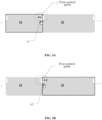
- separators may be used as distinguishing markers for different intervals.
- the separators can be any indicators for segmenting a video stream into different intervals, comprising but not limited to one or more of text identifiers, letter identifiers, pattern identifiers, color identifiers, etc.
- separators each comprising two opposing trapezoidal patterns are used to segment a video stream into multiple intervals.
- a separator 1 of interval Q1 and Q2 comprises two trapezoidal patterns a1 and a2.
- a part of the separator is used as a first control point of an adjacent target interval. This first control point is used to isolate the speed adjustment of the target interval from the speed adjustment of another interval.
- a first sticky control switch on the target interval which may be a control displayed on the visualization interface, etc.
- an end position of the movement operation on the first control point on the editing track is obtained, which is then aligned with a segmentation position of another adjacent interval. This ensures that other separators and intervals on the audio/video edit track can follow the movement of the first control point.
- the first control point is used separately to control the playback speed of video frames within its corresponding target interval. Different intervals correspond to different first control points, thus enabling independent playback speed adjustment for video frames within different intervals.
- the positions set of the first control points in the adjacent target intervals may be different.
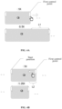
- the first control point is placed at the end of the target interval.
- an interval between a left separator pattern and a right separator pattern can be defined by the left separator pattern and the right separator pattern. Therefore, the left separator pattern, i.e., a separator pattern corresponding to the end of the target interval, can be used as the first control point of the left adjacent target interval, as shown in FIG. 3A ; If the separator is as shown in FIG. 2 above, the trapezoidal pattern al, i.e., the left pattern of separator 1, can be used as the first control point, which is used to control the playback speed of video frames in the left adjacent interval Q1 of the trapezoidal pattern a1.
- the first control point is placed at the start of the target interval.
- an interval between a left separator pattern and a right separator pattern can be defined by the left separator pattern and the right separator pattern. Therefore, the left separator pattern, i.e., a separator pattern corresponding to the start of the target interval, can be used as the first control point of the left adjacent target interval, as shown in FIG. 3B .
- the trapezoidal pattern a2 i.e., the right pattern of separator 1
- the first control point which is used to control the playback speed of video frames within the right adjacent interval Q2 of the trapezoidal pattern a2.
- a second control point is also provided.
- the second control point is used for variable speed adjustment of video frames within the target range.
- the relevant description of the second control point can be found in the following embodiments.
- step 102 in response to a movement operation on the first control point, a speed change amount is adjusted based on a position of the first control point on the editing track to control the speed of video frames within the target interval to vary according to the adjusted speed change amount, and a displayed length of the target interval on the editing track is increased or decreased according to a playback duration of the speed-changed video frames.
- the first control point is used to adjust the playback speed of video frames within the target interval. Therefore, in response to the movement operation on the first control point, the playback speed of video frames within the target interval can be controlled.
- the movement operation on the first control point can be triggered by a drag operation, a voice, or other means not specifically listed herein.
- the first control point in response to the movement operation on the first control point, the first control point is controlled to move on the editing track; a speed change amount is adjusted based on the position of the first control point on the editing track, so as to control the speed of relevant video frames within the target interval to change according to the adjusted speed change amount.
- a uniform change in the playback speed of the video frames within the target interval is controlled based on the first control point, and the degree of speed change depends on the movement length of the first control on the editing track.
- the displayed length of the target interval on the editing track can be increased or decreased according to a playback duration of the speed-changed video frames.
- a highlighted rectangular box can be used to indicate the range of the current target interval on the audio or video editing track.
- the method of adjusting, in response to the movement operation on the first control point, the speed change amount based on the position of the first control point on the editing track is different, as exemplarily described below.
- the end position of a target interval is used as the first control point of the left adjacent target interval, in response to a right movement operation on the first control point, the end position of the target interval is moved to the right on the editing track, thereby the speed change amount is decreased based on the position of the first control point on the editing track, while the start position of the target interval remains unchanged on the editing track.
- the video frames corresponding to each target interval remain unchanged. Adjusting the first control point to change the end position of the target interval on the editing track and moving the end position of the target interval to the right on the editing track can be equivalently considered as increasing the playback duration of the video frames corresponding to the target interval. Thus, the playback speed of the video frames within the target interval is correspondingly decreased. The speed change amount is decreased based on the position of the first control point on the editing track to decrease the playback speed of the video frames within the target interval.
- the end position of the target interval is moved to the right on the editing track, thereby the speed change amount is decreased based on the position of the first control point on the editing track. For example, if the end position of the target interval on the editing track is moved to the right by L1, the speed change amount is reduced by 0.5X, resulting in the playback speed of the video frames within the target interval being decreased from the original 1X to 0.5X.
- the end position of the target interval on the editing track in response to a left movement operation on the first control point, is moved to the left, such that the speed change amount is increased based on the position of the first control point on the editing track, while the start position of the target interval on the editing track remains unchanged.
- the video frames corresponding to each target interval remain unchanged. Adjusting the first control point to change the end position of the target interval on the editing track and moving the end position of the target interval to the left on the editing track can be equivalently considered as decreasing the playback duration of the video frames corresponding to the target interval. Thus, the playback speed of the video frames within the target interval is correspondingly increased. The speed change amount is increased based on the position of the first control point on the editing track to increase the playback speed of the video frames within the target interval.
- the end position of the target interval is moved to the left on the editing track, thereby the speed change amount is increased based on the position of the first control point on the editing track. For example, if the end position of the target interval on the editing track is moved to the right by L2, the speed change amount is increased by 0.25X, resulting in the playback speed of the video frames within the target interval being increased from the original 1X to 1.25X.
- the start position of the target interval is used as the first control point of the right adjacent target interval, in response to a right movement operation on the first control point, the start position of the target interval is moved to the right on the editing track, such that the speed change amount is increased based on the position of the first control point on the editing track, while the end position of the target interval on the editing track remains unchanged.
- the video frames corresponding to each target interval remain unchanged. Adjusting the first control point to change the start position of the target interval on the editing track and moving the start position of the target interval to the right on the editing track can be equivalently considered as decreasing the playback duration of the video frames corresponding to the target interval. Thus, the playback speed of the video frames within the target interval is correspondingly increased. The speed change amount is increased based on the position of the first control point on the editing track to increase the playback speed of the video frames within the target interval.
- the start position of the target interval is moved to the right on the editing track, thereby the speed change amount is increased based on the position of the first control point on the editing track. For example, if the start position of the target interval on the editing track is moved to the right by L3, the speed change amount is increased by 0.25X, resulting in the playback speed of the video frames within the target interval being increased from the original 1X to 1.25X.
- the start position of the target interval on the editing track is moved to the left, such that the speed change amount is decreased based on the position of the first control point on the editing track, while the end position of the target interval on the editing track remains unchanged.
- the video frames corresponding to each target interval remain unchanged. Adjusting the first control point to change the start position of the target interval on the editing track and moving the start position of the target interval to the left on the editing track can be equivalently considered as increasing the playback duration of the video frames corresponding to the target interval. Thus, the playback speed of the video frames within the target interval is correspondingly decreased. The speed change amount is decreased based on the position of the first control point on the editing track to decrease the playback speed of the video frames within the target interval.
- the start position of the target interval is moved to the left on the editing track, and the speed change amount is decreased based on the position of the first control point on the editing track. For example, if the start position of the target interval on the editing track is moved to the left by L4, the speed change amount is reduced by 0.25X, resulting in the playback speed of the video frames within the target interval being decreased from the original 1X to 0.75X.
- step 103 in response to a movement operation on the second control point within the target interval, a slope of a speed curve is adjusted based on a position of the second control point within the target interval, and the speed of the video frames within the target interval is controlled to vary according to the speed curve with a slope adjusted.
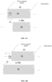
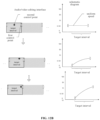
- the first control point mentioned above is only used to control a uniform change in the playback speed of video frames within the target interval, for example, as shown in FIG. 6A , if the target interval contains 10 video frames, these 10 video frames have the same playback speed that is changed uniformly, an effect achieved based on the first control point is a uniform increase or decrease in the playback speed of these 10 video frames.
- the playback speed of each video frame is the same (the width of each video frame in the figure reflects the playback speed of the video frame).
- the above playback speed adjustment based only on the first control point is not sufficient to achieve a high level of adjustment refinement in display. For example, as shown in FIG. 6B , if the target interval contains 10 video frames, a user may want the playback speed of these 10 video frames to be gradually decreased or increased (the width of the video frame in the figure reflects the playback speed of the video frame).
- a second control point is also provided for the target interval.
- the second control point can be presented as, but is not limited to, one or more of a text identifier, a letter identifier, a pattern identifier, and a color identifier, etc.
- the speed of the video frames within the target interval changes according to a speed curve with a slope adjusted.
- the vertical axis of the speed curve corresponds to the playback speed
- the horizontal axis corresponds to the video frames of the target interval.
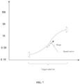
- the slope of the speed curve can determine the playback speed of video frames within the target range, and can be used to refine the variable speed adjustment of the video frames. For example, referring to FIG. 7 , the steeper the speed curve, the greater the rate of change of the corresponding playback speed; in contrast, the smoother the speed curve, the lower the rate of change of the corresponding playback speed.
- the method of adjusting the slope of the speed curve based on the position of the second control point within the target interval is different. These different adjustment methods are described in the following embodiments, and will not be repeated here.
- the first control point is mainly used for overall control on the playback speed of video frames within the corresponding target interval. Therefore, as shown in FIG. 6A above, in response to the video frames within the target interval are played back at a constant speed, the video frames within the target interval are controlled to be played back at a constant speed that is increased or decreased according to the adjusted speed change amount.
- the first control point can still achieve the effect of an overall change based on the variable speed of the video frames. That is, in response to the video frames within the target interval are played back at non-uniform speeds based on the speed curve, the video frames within the target interval are all controlled to be played back at non-uniform speeds that are increased or decreased according to an adjusted speed change amount.
- the target interval contains 10 video frames
- these 10 video frames have playback speeds that gradually decrease as determined by the speed curve. If the corresponding speed change amount determined based on the movement operation on the first control point is a speed decrease of 0.5X, all the playback speeds are decreased by 0.5X based on the gradually decreased playback speeds of these 10 video frames.
- the multimedia material clip is segmented into multiple intervals on an editing track for an audio or a video.
- the multiple intervals comprise a target interval.
- a first control point and a second control point corresponding to the target interval are provided on the multimedia material clip.
- a speed change amount is adjusted based on the position of the first control point on the editing track, so as to control the speed of the video frames within the target interval to change according to the adjusted speed change amount, and the displayed length of the target interval on the editing track is increased or decreased according to a playback duration of the speed-changed video frames.
- a slope of a speed curve is adjusted based on a position of the second control point within the target interval, and the speed of the video frames within the target interval is controlled to vary according to the speed curve with a slope adjusted. Therefore, through segmenting the multimedia material into multiple intervals, the playback speed of video frames within these intervals can be adjusted independently, and an overall speed adjustment can be made based on a first control point for video frames within each interval. It is also possible to achieve variable speed adjustment based on a second control point to allow different playback speeds of different video frames within the same interval. As a result, fine adjustment of video frame playback speed can be achieved, and the accuracy and efficiency of video frame playback speed adjustment can be improved.
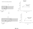
- a schematic diagram corresponding to the multimedia material clip can also be displayed in an area of the function panel.
- the schematic diagram comprises a speed control indicator corresponding to the first control point, and a speed adjusted based on the first control point for the target interval is displayed in a corresponding area of the schematic interval. Therefore, based on the association display of the schematic diagram and the audio or video editing track, the speed adjustment effect of the current first control point can be visually displayed.
- a schematic diagram is displayed in association with the multimedia material clip in an area of the function panel.
- the schematic diagram comprises a speed control indicator corresponding to the first control point and a schematic interval Qs' corresponding to the target interval Qs.
- the first control point a2s is used as the speed control indicator of the adjacent schematic interval, and a speed of the target interval adjusted according to the first control point is displayed in the corresponding area of the schematic interval Qs'.
- the adjusted speed in the figure is 0.5X.
- the speeds of the video frames adjusted based on the second control point are also displayed on the schematic diagram, i.e., the slope of the speed curve is adjusted based on the position of the second control point within the target interval; a speed curve with a slope adjusted is displayed in the schematic interval in association with a speed range of the speed curve.
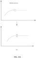
- speeds corresponding to speed control indicators of adjacent schematic intervals are compared. If the speed control indicator at the end position of the left interval and the speed control indicator at the start position of the right interval correspond to the same speed, as shown in FIG. 9A , the two speed control indicators are combined and saved as one speed control point for display on a mobile device; If the speed control indicator at the end position of the left interval and the speed control indicator at the start position of the right interval correspond to different speeds, as shown in FIG. 9B , the two speed control indicators are saved as two speed control points for display on a mobile device respectively.
- the schematic diagram in order to further facilitate user adjustment, can be saved as a draft and synchronously displayed on other devices.
- a schematic diagram adjusted on a PC can be synchronized to a mobile device for display.
- the schematic diagram can be operated by a user on the mobile terminal; if a part of the separator is used as the first control point, in the embodiments, for a separator consisting of two parts, these parts can be displayed in other patterns on the mobile terminal. That is, display conversion is performed on the mobile terminal to adapt to the display rules of the mobile terminal.
- the different parts of a separator are displayed in the form of dots that are separated by m pixels. If it is detected that one dot is dragged by the user, the x-axis coordinate of the dot can be changed accordingly. When synchronized back to a PC, two corresponding dots are displayed as different parts of a separator.
- the interval between different parts of the separator is one frame on the PC, and there is also a limit to the minimum number of video frames comprised in an interval, for example, the minimum number cannot be less than 3 frames, when the x-axis position corresponding to the dragged dot on the mobile device conflicts with the display rules on the PC, the dot can be discarded after the interaction, without displaying a separator part corresponding to the dot on the PC.
- the first separator part of the interval can be retained and other separator part of the interval can be deleted.
- a schematic diagram associated with the multimedia material clip is displayed in an area of the function panel.
- the schematic diagram comprises a schematic interval corresponding to the target interval.
- a speed adjustment result of the first control point and the second control point on the target interval is displayed in a corresponding area of the schematic interval, thereby improving the intuitiveness and user experience of the speed adjustment.
- a trigger operation on the second control point is used to achieve a variable speed change of the video frames within the target interval.
- the second control point determines the slope of the speed curve for the variable speed change. The following is an example of how to adjust the slope of the speed curve based on the position of the second control point within a target interval.
- adjusting a slope of a speed curve based on the position of the second control point within the target interval comprises the following steps.
- adjusting a slope of the speed curve based on the position where the second control point is added within the target interval.
- different positions of the second control point within the target interval corresponds to different slopes.
- the slope of the speed curve is set to zero to produce a constant speed line that matches the speed set by the first control point, so that the video frames within the target interval are controlled to be played back at a constant speed.
- the position of the dot in the target interval determines the slope of the speed curve; if the dot is set at the middle position of the track corresponding to the target interval, the corresponding slope is 0. In this case, the video frames within the target interval are played back at a constant speed.
- the slope changes accordingly, for example, the average slope of the speed curve gradually increases.
- the playback speed of the video frames within the target interval changes with the slope to achieve a playback speed adjustment;
- the slope changes accordingly, for example, the average slope of the speed curve gradually decreases.
- the playback speed of the video frames within the target interval changes with the slope to achieve a playback speed adjustment.
- the slope of the speed curve can also be adjusted based on the movement position of the second control point within the target interval in response to a movement operation of the second control point.
- the slope of the speed curve can be further adjusted based on the movement position of the second control point within the target interval. For example, if the slope corresponding to the adding position of the second control point within the target interval is 0, the slope of the speed curve can be adjusted with the right or left movement of the second control point.
- candidate movement positions of the second control point within the target interval are obtained, and a correspondence between those candidate positions and their corresponding slope values is constructed.
- the change in slope between different candidate positions can be associated with or not associated with the position change of the candidate positions, which is not limited herein.
- a target position to which the second control point moves is determined, and a slope value corresponding to the target position is determined by querying the above correspondence to adjust the slope of the speed curve.
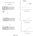
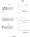
- the slope of the speed curve in response to a movement of the second control point between the middle position and the end position of the target interval, is adjusted to generate an ascending speed curve.
- the speed curve In response to the second control point located at the end position of the target interval, the speed curve has the largest slope value. That is, in response to the second control point located at the end position of the target interval, the ascending speed curve becomes overall steeper.
- the largest slope value can be understood as the largest average slope value of the speed curve.
- the slope change rate from the start position to the middle position of the target interval is the greatest, thereby controlling the playback speed of video frames within the target interval according to the ascending speed curve.
- the movement of the second control point is associated with the slope increase, which can improve the interactive feeling of the operation.
- the ascending speed curve can be in any form base on an ascending trend and the slope gradually increases from the start position to the middle position of the target interval.
- the slope gradually increases from the start position to the middle position of the target interval, and gradually decreases from the middle position to the end position of the target interval with the center position point as the center of symmetry.
- the slope change rate from the start position to the middle position of the target interval gradually increases. If the second control point is located at the end position of the target interval, the slope change rate from the start position to the middle position of the target interval is the greatest. In this case, the speed curve has the largest slope value and the speed curve is overall steepest.
- the speed curve can be a sine wave curve with positive slopes. From the start position to the end position of the target interval, the slope of the speed curve gradually decreases. Referring to FIG. 12B , as the second control point approaches the end position of the target interval, the slope change rate from the start position to the middle position of the target interval gradually increases. If the second control point is located at the end position of the target interval, the speed curve has the largest slope value.
- the slope of the speed curve in response to a movement of the second control point between the middle position and the end position of the target interval, is adjusted to generate a descending speed curve.
- the speed curve In response to the second control point located at the start position of the target interval, the speed curve has the smallest slope value, thereby controlling the playback speed of video frames within the target interval according to the descending speed curve.
- the smallest slope value due to the negative slope of the descending speed curve, the smaller the slope value corresponding to the speed curve, the steeper the speed curve.
- the smallest slope value can be understood as the smallest average value of the slope values at the points comprised in the speed curve.
- the movement of the second control point is associated with the slope increase, which can improve the interactive feeling of the operation.
- the descending speed curve can be in any form in response to a descending trend and the absolute value of the slope gradually increases from the start position to the middle position of the target interval.
- the absolute value of the slope gradually increases from the start position to the middle position of the target interval, and gradually decreases from the middle position to the end position of the target interval with the center position point as the center of symmetry.
- the change rate of the absolute value of the slope gradually increases from the start position to the middle position of the target interval. If the second control point is located at the start position of the target interval, the speed curve has the smallest negative slope value and the speed curve is steepest.
- the speed curve can be a sine wave curve with a negative slope. From the start position to the end position of the target interval, the absolute value of slope of the speed curve gradually increases. Referring to FIG. 13B , as the second control point approaches the start position of the target interval, the slope change rate from the start position to the middle position of the target interval gradually increases. If the second control point is located at the start position of the target interval, the speed curve has the smallest negative slope value, and the speed curve is steepest.
- the speed curve has a limited speed range, and a speed adjustment range is limited based on the speed range.
- a speed range of the adjusted speed curve is determined, and the speed range is displayed in a preset area at the position of the second control point within the target interval.
- the speed range may be displayed in any form, such as a tag, floating display, etc., which indicates a speed adjustment range corresponding to the current second control point.
- n.nX speed is displayed in the preset area at a position with respect to the target interval. If the speed is variable, "a.aX ⁇ b. bX speed” is displayed in the preset area at a position with respect to the target interval, wherein a.a is the playback speed at the start position, and b.b is the playback speed at the end position.
- the speed range of the adjusted speed curve can be determined based on the proximity between the speed adjusted by the first control point and the boundary values of the speed-up range corresponding to the slope of the speed curve.
- the speed adjusted by the first control point can be used as the center value, and the closest boundary value can be used as a boundary value of the speed range.
- a first speed time value is calculated based on 0.1X and 0.5 X
- a second speed time value is calculated based on 10X and 0.5X.
- a smaller speed time value is determined, i.e., the boundary value corresponding to the first speed time value is 0.1X. Therefore, with 0.1X as a boundary value and 0.5X as the center value, the speed range of the speed curve is determined to be 0.1X-1X.
- a sum of the speed and a preset adjustment value, and a difference between the first control point and the preset adjustment value are calculated.
- the sum and the difference are used as the maximum boundary value and the minimum boundary value of the speed range, respectively, to determine the speed range of the adjusted speed curve.
- the minimum value of the speed-up range is used as the minimum boundary value of the speed range.
- the maximum value of the speed-up range is used as the maximum boundary value of the speed range.
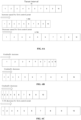
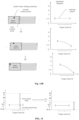
- the state of the speed adjustment performed on the video frames within the target interval is displayed. Based on the speed curve with a slope adjusted, video frames with decreased speeds within the target interval are widened for display, and video frames with increased speeds within the target interval are narrowed for display. The speed adjustment effect of the corresponding video frame is reflected by the width of the video frames.
- the corresponding video frames can be displayed normally by frame extraction display, which is not specifically limited here.
- the playback speed is a constant speed set to 0.5X, and each video frame has the same width; if the user drags the second control point to the end position of the target interval, then video frames with decreased speeds within the target interval are widened for display, and video frames with increased speeds within the target interval are narrowed for display based on a speed curve with a slope adjusted.
- speed alignment is performed if different intervals have similar speeds at their intersection.
- a speed curve with a slope adjusted is obtained based on the position of the second control point within the target interval, and a playback speed at the end position of the target interval is determined based on the speed curve with a slope adjusted. If the difference between the playback speed at the end of the target interval and the playback speed at the beginning of an adjacent interval is less than a preset threshold, which is calibrated based on experimental data, the speed at the end of the target interval is aligned with the speed at the beginning of the adjacent interval. This can ensure smooth video playback while meeting users' personal needs for speed adjustment.
- the playback speed at the end position of the target interval is aligned with the playback speed at the start position of the adjacent interval.
- the slope of the speed curve can be flexibly determined based on a movement operation on the second control point, so as to meet the requirements for variable speed adjustment for the playback speed of video frames within the target interval, thereby improving the flexibility of the adjustment.
- the present disclosure further provides a multimedia clip speed adjustment apparatus.
- FIG. 17 is a schematic structural diagram of a multimedia clip speed adjustment apparatus according to an embodiment of the present disclosure.
- the apparatus can be implemented by software and/or hardware, and can generally be integrated into an electronic device for speed adjustment of audio/video information.
- the apparatus comprises: a segmentation module 1710, a first speed change control module 1720, and a second speed change control module 1730.
- the segmentation module 1710 is used for segmenting a multimedia material clip into multiple intervals on an editing track for an audio or a video, the multiple intervals comprising a target interval, wherein a first control point and a second control point corresponding to the target interval are provided on the multimedia material clip.
- the first speed change control module 1720 is used for adjusting, in response to a movement operation on the first control point, a speed change amount based on a position of the first control point on the editing track, controlling the speed of video frames within the target interval to vary according to the adjusted speed change amount, and increasing or decreasing a displayed length of the target interval on the editing track according to a playback duration of the speed-changed video frames.
- the second speed change control module 1730 is used for adjusting, in response to a movement operation on the second control point, a slope of a speed curve based on a position of the second control point within the target interval, and controlling the speed of the video frames within the target interval to vary according to the speed curve with a slope adjusted.
- the multimedia clip speed adjustment apparatus provided in this embodiment of the present disclosure can perform the multimedia clip speed adjustment method provided in any embodiment of the present disclosure, and has corresponding functional modules to implement the method and achieve the beneficial effect of the present disclosure.
- the present application further provides a computer program product containing a computer program/instructions that, when executed by a processor, implement the multimedia clip speed adjustment method provided in the above embodiment.
- FIG. 18 is a schematic structural diagram of an electronic device provided in embodiments of the present disclosure.
- the electronic device 1800 of the embodiment of the present disclosure may comprise, but not limited to, a mobile terminal such as a mobile phone, a notebook computer, a digital broadcast receiver, a PDA (Personal Digital Assistant), a PAD (tablet computer), a PMP (Portable Multimedia Player), an on-board terminal (such as an on-board navigation terminal), and a fixed terminal such as a digital TV, a desktop computer, and the like.
- a mobile terminal such as a mobile phone, a notebook computer, a digital broadcast receiver, a PDA (Personal Digital Assistant), a PAD (tablet computer), a PMP (Portable Multimedia Player), an on-board terminal (such as an on-board navigation terminal), and a fixed terminal such as a digital TV, a desktop computer, and the like.
- PDA Personal Digital Assistant
- PAD tablet computer
- PMP Portable Multimedia Player
- an on-board terminal such as an on-board navigation terminal
- a fixed terminal such as a digital TV, a desktop computer,
- the electronic device 1800 may comprise a processing device (e.g., a central processing unit, a graphics processor) 1801, which may perform various appropriate actions and processes according to a program stored in Read Only Memory (ROM) 1802 or a program loaded from storage device 1808 into Random Access Memory (RAM) 1803.
- ROM Read Only Memory
- RAM Random Access Memory
- various programs and data required for the operation of the electronic device 1800 are also stored.
- the processing device 1801, ROM 1802, and RAM 1803 are connected to each other through a bus 1804.
- An input/output (I/O) interface 1805 is also connected to the bus 1804.
- the following devices can be connected to the I/O interface 1805: input devices 1806 comprising, for example, a touch screen, a touch pad, a keyboard, a mouse, a camera, a microphone, an accelerometer, a gyroscope, etc; output devices 1807 comprising a liquid crystal display (LCD), a speaker, a vibrator, etc.; a storage device 1808 such as a magnetic tape, a hard disk, etc; and a communication device 1809.
- the communication device 1809 enables the electronic device 1800 to communicate in a wireless or wired manner with other devices to exchange data.
- FIG. 18 shows the electronic device 1800 with various components, it should be understood that it is not required to implement or have all of these components. Alternatively, more or fewer components can be implemented or provided.
- an embodiment of the present disclosure comprises a computer program product, which comprises a computer program carried on a non-transitory computer readable medium, and containing program code for executing the method shown in the flowchart.
- the computer program may be downloaded and installed from the network through the communication device 1809, or installed from the storage device 1808, or from the ROM 1802.
- the processing device 1801 the above functions defined in the multimedia clip speed adjustment method according to the embodiment of the present disclosure are performed.
- the computer readable medium in the present disclosure may be a computer readable signal medium or a computer readable storage medium, or any combination of thereof.
- the computer readable storage medium can be, for example, but not limited to, an electronic, magnetic, optical, electromagnetic, infrared, or semiconductor system, apparatus, or device, or any combination of the above. More specific examples of the computer readable storage medium may comprise, but are not limited to: electrical connection with one or more wires, portable computer disk, hard disk, random access memory (RAM), read only memory (ROM), erasable programmable read only memory (EPROM or flash), fiber optics, portable compact disk Read only memory (CD-ROM), optical storage device, magnetic storage device, or any suitable combination of the foregoing.
- a computer readable storage medium can be any tangible medium that can contain or store a program, which can be used by or in connection with an instruction execution system, apparatus or device.
- a computer readable signal medium may comprise a data signal that is propagated in the baseband or as part of a carrier, carrying computer readable program code. Such propagated data signals can take a variety of forms comprising, but not limited to, electromagnetic signals, optical signals, or any suitable combination of the foregoing.
- the computer readable signal medium can also be any computer readable medium other than a computer readable storage medium, which can transmit, propagate, or transport a program for use by or in connection with the instruction execution system, apparatus, or device.
- Program code embodied on a computer readable medium can be transmitted by any suitable medium, comprising but not limited to wire, fiber optic cable, RF (radio frequency), etc., or any suitable combination of the foregoing.
- a client and a server can communicate using any currently known or future developed network protocol such as HTTP (HyperText Transfer Protocol), and can be interconnected by any form or medium of digital data communication, e.g., a communication network.
- HTTP HyperText Transfer Protocol
- Examples of communication networks comprise a local area network ("LAN”) and a wide area network (“WAN”), the Internet, and end-to-end networks (for example, ad hoc end-to-end networks), as well as any currently known or future developed networks.
- the above computer readable medium may be comprised in the electronic device described above; or it may exist alone without being assembled into the electronic device.
- the computer-readable medium carries one or more programs that cause, when executed by the electronic device, the electronic device to perform steps of:
- the playback speed of video frames within these intervals can be adjusted independently, and an overall speed adjustment can be made based on a first control point for video frames within each interval. It is also possible to achieve variable speed adjustment based on a second control point to allow different playback speeds of different video frames within the same interval. As a result, fine speed adjustment can be achieved for the video frames, and the accuracy and efficiency of speed adjustment can be improved.
- the computer program code for executing operations of the present disclosure may be complied by any combination of one or more program design languages, the program design languages comprising object-oriented program design languages, such as Java, Smalltalk, C++, etc, as well as conventional procedural program design languages, such as "C" program design language or similar program design language.
- a program code may be completely or partly executed on a user computer, or executed as an independent software package, partly executed on the user computer and partly executed on a remote computer, or completely executed on a remote computer or server.
- the remote computer may be connected to the user computer through various kinds of networks, comprising local area network (LAN) or wide area network (WAN), or connected to external computer (for example using an internet service provider via Internet).
- LAN local area network
- WAN wide area network
- Internet for example using an internet service provider via Internet
- An embodiment of the present disclosure further provides a computer product comprising instructions that, when executed by a processor, cause the processor to implement the multimedia clip speed adjustment method provided in the embodiment of the present disclosure.
- each block in the flowchart or block diagrams may represent a module, segment, or portion of code, which comprises one or more executable instructions for implementing the specified function or functions.
- the functions noted in the block may occur out of the order noted in the drawings. For example, two blocks shown in succession may be executed substantially concurrently, or the blocks may sometimes be executed in the reverse order, depending upon the functionality involved.
- the units involved in the embodiments described in the present disclosure can be implemented in software or hardware. Wherein, the names of the units do not constitute a limitation on the units themselves under certain circumstances.
- exemplary types of hardware logic components comprise: Field Programmable Gate Array (FPGA), Application Specific Integrated Circuit (ASIC), Application Specific Standard Product (ASSP), System on Chip (SOC), Complex Programmable Logic Device (CPLD), etc.
- FPGA Field Programmable Gate Array
- ASIC Application Specific Integrated Circuit
- ASSP Application Specific Standard Product
- SOC System on Chip
- CPLD Complex Programmable Logic Device
- a machine-readable medium may be a tangible medium, which may contain or store a program for use by or in connection with an instruction execution system, apparatus, or device.
- the machine-readable medium may be a machine-readable signal medium or a machine-readable storage medium.
- the machine-readable medium may comprise, but is not limited to, an electronic, magnetic, optical, electromagnetic, infrared, or semiconductor system, apparatus, or device, or any suitable combination of thereof.
- machine-readable storage medium may comprise electrical connection with one or more wires, portable computer disk, hard disk, random access memory (RAM), read only memory (ROM), erasable programmable read only memory (EPROM or flash), fiber optics, portable compact disk Read only memory (CD-ROM), optical storage device, magnetic storage device, or any suitable combination of the foregoing.
- RAM random access memory
- ROM read only memory
- EPROM or flash erasable programmable read only memory
- CD-ROM compact disk Read only memory
- optical storage device magnetic storage device, or any suitable combination of the foregoing.
Landscapes
- Engineering & Computer Science (AREA)
- Multimedia (AREA)
- Signal Processing (AREA)
- Databases & Information Systems (AREA)
- Human Computer Interaction (AREA)
- Television Signal Processing For Recording (AREA)
- User Interface Of Digital Computer (AREA)
- Studio Devices (AREA)
- Two-Way Televisions, Distribution Of Moving Picture Or The Like (AREA)
Applications Claiming Priority (2)
| Application Number | Priority Date | Filing Date | Title |
|---|---|---|---|
| CN202210622737.1A CN117201716B (zh) | 2022-06-01 | 2022-06-01 | 多媒体片段的速度调整方法、装置、设备及介质 |
| PCT/CN2023/097371 WO2023232066A1 (zh) | 2022-06-01 | 2023-05-31 | 多媒体片段的速度调整方法、装置、设备及介质 |
Publications (2)
| Publication Number | Publication Date |
|---|---|
| EP4407979A1 true EP4407979A1 (de) | 2024-07-31 |
| EP4407979A4 EP4407979A4 (de) | 2025-04-16 |
Family
ID=88987464
Family Applications (1)
| Application Number | Title | Priority Date | Filing Date |
|---|---|---|---|
| EP23815243.3A Pending EP4407979A4 (de) | 2022-06-01 | 2023-05-31 | Verfahren und vorrichtung zur einstellung der geschwindigkeit eines multimedia-clips, vorrichtung und medium |
Country Status (6)
| Country | Link |
|---|---|
| US (1) | US12293778B2 (de) |
| EP (1) | EP4407979A4 (de) |
| JP (1) | JP7562884B2 (de) |
| KR (1) | KR102834050B1 (de) |
| CN (1) | CN117201716B (de) |
| WO (1) | WO2023232066A1 (de) |
Family Cites Families (17)
| Publication number | Priority date | Publication date | Assignee | Title |
|---|---|---|---|---|
| US6964021B2 (en) * | 2000-08-19 | 2005-11-08 | Lg Electronics Inc. | Method and apparatus for skimming video data |
| US7676142B1 (en) * | 2002-06-07 | 2010-03-09 | Corel Inc. | Systems and methods for multimedia time stretching |
| US7725828B1 (en) * | 2003-10-15 | 2010-05-25 | Apple Inc. | Application of speed effects to a video presentation |
| US8170396B2 (en) * | 2007-04-16 | 2012-05-01 | Adobe Systems Incorporated | Changing video playback rate |
| US8078456B2 (en) * | 2007-06-06 | 2011-12-13 | Broadcom Corporation | Audio time scale modification algorithm for dynamic playback speed control |
| JP5261217B2 (ja) * | 2009-01-30 | 2013-08-14 | キヤノン株式会社 | 表示装置および表示方法 |
| CN102610254B (zh) * | 2011-01-19 | 2016-01-20 | 新奥特(北京)视频技术有限公司 | 一种读取任意多时间点数据实现变速与倒放的方法和系统 |
| US8849948B2 (en) * | 2011-07-29 | 2014-09-30 | Comcast Cable Communications, Llc | Variable speed playback |
| KR101909030B1 (ko) * | 2012-06-08 | 2018-10-17 | 엘지전자 주식회사 | 비디오 편집 방법 및 이를 위한 디지털 디바이스 |
| US9014544B2 (en) * | 2012-12-19 | 2015-04-21 | Apple Inc. | User interface for retiming in a media authoring tool |
| KR101631190B1 (ko) * | 2014-05-21 | 2016-06-16 | 주식회사 엘지유플러스 | 주문형 비디오 서비스 제공 방법 및 시스템 |
| US10102423B2 (en) | 2016-06-30 | 2018-10-16 | Snap Inc. | Object modeling and replacement in a video stream |
| CN108235123B (zh) | 2016-12-15 | 2020-09-22 | 阿里巴巴(中国)有限公司 | 视频播放方法及装置 |
| CN113825019B (zh) * | 2020-06-19 | 2022-11-11 | 北京字节跳动网络技术有限公司 | 视频变速播放方法、装置、电子设备及计算机可读介质 |
| CN112738627B (zh) * | 2020-12-23 | 2022-05-20 | 上海哔哩哔哩科技有限公司 | 播放控制方法及装置 |
| CN113207027B (zh) * | 2021-03-29 | 2023-03-24 | 北京达佳互联信息技术有限公司 | 视频播放速度调节方法及装置 |
| CN114449313B (zh) * | 2022-02-10 | 2024-03-26 | 上海幻电信息科技有限公司 | 视频的音画面播放速率调整方法及装置 |
-
2022
- 2022-06-01 CN CN202210622737.1A patent/CN117201716B/zh active Active
-
2023
- 2023-05-31 WO PCT/CN2023/097371 patent/WO2023232066A1/zh not_active Ceased
- 2023-05-31 KR KR1020247037203A patent/KR102834050B1/ko active Active
- 2023-05-31 JP JP2023579684A patent/JP7562884B2/ja active Active
- 2023-05-31 EP EP23815243.3A patent/EP4407979A4/de active Pending
-
2024
- 2024-04-05 US US18/627,975 patent/US12293778B2/en active Active
Also Published As
| Publication number | Publication date |
|---|---|
| US20240290351A1 (en) | 2024-08-29 |
| JP7562884B2 (ja) | 2024-10-07 |
| WO2023232066A1 (zh) | 2023-12-07 |
| CN117201716A (zh) | 2023-12-08 |
| JP2024527710A (ja) | 2024-07-26 |
| US12293778B2 (en) | 2025-05-06 |
| CN117201716B (zh) | 2025-10-24 |
| EP4407979A4 (de) | 2025-04-16 |
| KR102834050B1 (ko) | 2025-07-17 |
| KR20240173204A (ko) | 2024-12-10 |
Similar Documents
| Publication | Publication Date | Title |
|---|---|---|
| US11956528B2 (en) | Shooting method using target control, electronic device, and storage medium | |
| EP4310653A1 (de) | Steuerungsanzeigeverfahren und -vorrichtung sowie elektronische vorrichtung und speichermedium | |
| CN109508128B (zh) | 搜索控件显示方法、装置、设备及计算机可读存储介质 | |
| CN110362225B (zh) | 触控屏采样频率控制方法、装置、介质及电子设备 | |
| CN111061574A (zh) | 一种对象分享方法及电子设备 | |
| WO2016165568A1 (zh) | 视频图像缩放方法和移动终端 | |
| EP4161065A1 (de) | Verfahren und gerät, speichermedium und vorrichtung zur steuerung der anzeige einer videorufschnittstelle | |
| CN111596817B (zh) | 图标移动方法及电子设备 | |
| EP4498216A1 (de) | Elementsteuerungsverfahren und -vorrichtung für eine informationseingabeseite, vorrichtung und medium | |
| JP7402330B2 (ja) | 目標対象表示方法、装置、電子機器、及びコンピュータ読み取り可能な媒体 | |
| JP7735591B2 (ja) | メディアコンテンツの表示方法、装置、機器、記憶媒体、及びプログラム | |
| WO2024001893A1 (zh) | 素材展示方法、装置、设备、计算机可读存储介质及产品 | |
| CN111190520A (zh) | 菜单项选择方法、装置、可读介质及电子设备 | |
| CN111492346A (zh) | 动态可配置的应用控制元素 | |
| US20230199262A1 (en) | Information display method and device, and terminal and storage medium | |
| US20250068311A1 (en) | Method, apparatus, electronic device and storage medium for display controlling | |
| CN110647286A (zh) | 屏幕元素控制方法、装置、设备、存储介质 | |
| JP7715918B2 (ja) | マルチメディアデータの処理方法、装置、機器及び媒体 | |
| US20230251777A1 (en) | Target object display method and apparatus, electronic device and non-transitory computer-readable medium | |
| EP4407979A1 (de) | Verfahren und vorrichtung zur einstellung der geschwindigkeit eines multimedia-clips, vorrichtung und medium | |
| US20250077015A1 (en) | Control method, control apparatus, and electronic device | |
| US20240411438A1 (en) | Display method and apparatus, electronic device, and storage medium | |
| CN116939269A (zh) | 显示控件方法、装置、电子设备、存储介质和程序产品 | |
| CN115908633A (zh) | 特效生成方法、装置、设备、计算机可读存储介质及产品 | |
| CN110633062A (zh) | 显示信息的控制方法、装置、电子设备及可读介质 |
Legal Events
| Date | Code | Title | Description |
|---|---|---|---|
| STAA | Information on the status of an ep patent application or granted ep patent |
Free format text: STATUS: THE INTERNATIONAL PUBLICATION HAS BEEN MADE |
|
| PUAI | Public reference made under article 153(3) epc to a published international application that has entered the european phase |
Free format text: ORIGINAL CODE: 0009012 |
|
| STAA | Information on the status of an ep patent application or granted ep patent |
Free format text: STATUS: REQUEST FOR EXAMINATION WAS MADE |
|
| 17P | Request for examination filed |
Effective date: 20240329 |
|
| AK | Designated contracting states |
Kind code of ref document: A1 Designated state(s): AL AT BE BG CH CY CZ DE DK EE ES FI FR GB GR HR HU IE IS IT LI LT LU LV MC ME MK MT NL NO PL PT RO RS SE SI SK SM TR |
|
| REG | Reference to a national code |
Ref country code: DE Ref legal event code: R079 Free format text: PREVIOUS MAIN CLASS: H04N0007010000 Ipc: G11B0027000000 |
|
| A4 | Supplementary search report drawn up and despatched |
Effective date: 20250317 |
|
| RIC1 | Information provided on ipc code assigned before grant |
Ipc: H04N 7/01 20060101ALI20250311BHEP Ipc: G11B 27/031 20060101ALI20250311BHEP Ipc: G11B 27/34 20060101ALI20250311BHEP Ipc: G11B 27/00 20060101AFI20250311BHEP |
|
| DAV | Request for validation of the european patent (deleted) | ||
| DAX | Request for extension of the european patent (deleted) | ||
| STAA | Information on the status of an ep patent application or granted ep patent |
Free format text: STATUS: EXAMINATION IS IN PROGRESS |