EP4407864A1 - Halterung und vorrichtungen zur montage eines solarpaneels auf dächern - Google Patents
Halterung und vorrichtungen zur montage eines solarpaneels auf dächern Download PDFInfo
- Publication number
- EP4407864A1 EP4407864A1 EP24150589.0A EP24150589A EP4407864A1 EP 4407864 A1 EP4407864 A1 EP 4407864A1 EP 24150589 A EP24150589 A EP 24150589A EP 4407864 A1 EP4407864 A1 EP 4407864A1
- Authority
- EP
- European Patent Office
- Prior art keywords
- base
- raised
- foot
- roof
- aperture
- Prior art date
- Legal status (The legal status is an assumption and is not a legal conclusion. Google has not performed a legal analysis and makes no representation as to the accuracy of the status listed.)
- Withdrawn
Links
Images





Classifications
-
- H—ELECTRICITY
- H02—GENERATION; CONVERSION OR DISTRIBUTION OF ELECTRIC POWER
- H02S—GENERATION OF ELECTRIC POWER BY CONVERSION OF INFRARED RADIATION, VISIBLE LIGHT OR ULTRAVIOLET LIGHT, e.g. USING PHOTOVOLTAIC [PV] MODULES
- H02S20/00—Supporting structures for PV modules
- H02S20/20—Supporting structures directly fixed to an immovable object
- H02S20/22—Supporting structures directly fixed to an immovable object specially adapted for buildings
- H02S20/23—Supporting structures directly fixed to an immovable object specially adapted for buildings specially adapted for roof structures
-
- F—MECHANICAL ENGINEERING; LIGHTING; HEATING; WEAPONS; BLASTING
- F24—HEATING; RANGES; VENTILATING
- F24S—SOLAR HEAT COLLECTORS; SOLAR HEAT SYSTEMS
- F24S25/00—Arrangement of stationary mountings or supports for solar heat collector modules
- F24S25/60—Fixation means, e.g. fasteners, specially adapted for supporting solar heat collector modules
- F24S25/61—Fixation means, e.g. fasteners, specially adapted for supporting solar heat collector modules for fixing to the ground or to building structures
-
- H—ELECTRICITY
- H02—GENERATION; CONVERSION OR DISTRIBUTION OF ELECTRIC POWER
- H02S—GENERATION OF ELECTRIC POWER BY CONVERSION OF INFRARED RADIATION, VISIBLE LIGHT OR ULTRAVIOLET LIGHT, e.g. USING PHOTOVOLTAIC [PV] MODULES
- H02S30/00—Structural details of PV modules other than those related to light conversion
- H02S30/10—Frame structures
-
- F—MECHANICAL ENGINEERING; LIGHTING; HEATING; WEAPONS; BLASTING
- F24—HEATING; RANGES; VENTILATING
- F24S—SOLAR HEAT COLLECTORS; SOLAR HEAT SYSTEMS
- F24S80/00—Details, accessories or component parts of solar heat collectors not provided for in groups F24S10/00-F24S70/00
- F24S2080/09—Arrangements for reinforcement of solar collector elements
-
- F—MECHANICAL ENGINEERING; LIGHTING; HEATING; WEAPONS; BLASTING
- F24—HEATING; RANGES; VENTILATING
- F24S—SOLAR HEAT COLLECTORS; SOLAR HEAT SYSTEMS
- F24S25/00—Arrangement of stationary mountings or supports for solar heat collector modules
- F24S25/60—Fixation means, e.g. fasteners, specially adapted for supporting solar heat collector modules
- F24S25/61—Fixation means, e.g. fasteners, specially adapted for supporting solar heat collector modules for fixing to the ground or to building structures
- F24S25/615—Fixation means, e.g. fasteners, specially adapted for supporting solar heat collector modules for fixing to the ground or to building structures for fixing to protruding parts of buildings, e.g. to corrugations or to standing seams
-
- Y—GENERAL TAGGING OF NEW TECHNOLOGICAL DEVELOPMENTS; GENERAL TAGGING OF CROSS-SECTIONAL TECHNOLOGIES SPANNING OVER SEVERAL SECTIONS OF THE IPC; TECHNICAL SUBJECTS COVERED BY FORMER USPC CROSS-REFERENCE ART COLLECTIONS [XRACs] AND DIGESTS
- Y02—TECHNOLOGIES OR APPLICATIONS FOR MITIGATION OR ADAPTATION AGAINST CLIMATE CHANGE
- Y02B—CLIMATE CHANGE MITIGATION TECHNOLOGIES RELATED TO BUILDINGS, e.g. HOUSING, HOUSE APPLIANCES OR RELATED END-USER APPLICATIONS
- Y02B10/00—Integration of renewable energy sources in buildings
- Y02B10/10—Photovoltaic [PV]
-
- Y—GENERAL TAGGING OF NEW TECHNOLOGICAL DEVELOPMENTS; GENERAL TAGGING OF CROSS-SECTIONAL TECHNOLOGIES SPANNING OVER SEVERAL SECTIONS OF THE IPC; TECHNICAL SUBJECTS COVERED BY FORMER USPC CROSS-REFERENCE ART COLLECTIONS [XRACs] AND DIGESTS
- Y02—TECHNOLOGIES OR APPLICATIONS FOR MITIGATION OR ADAPTATION AGAINST CLIMATE CHANGE
- Y02B—CLIMATE CHANGE MITIGATION TECHNOLOGIES RELATED TO BUILDINGS, e.g. HOUSING, HOUSE APPLIANCES OR RELATED END-USER APPLICATIONS
- Y02B10/00—Integration of renewable energy sources in buildings
- Y02B10/20—Solar thermal
-
- Y—GENERAL TAGGING OF NEW TECHNOLOGICAL DEVELOPMENTS; GENERAL TAGGING OF CROSS-SECTIONAL TECHNOLOGIES SPANNING OVER SEVERAL SECTIONS OF THE IPC; TECHNICAL SUBJECTS COVERED BY FORMER USPC CROSS-REFERENCE ART COLLECTIONS [XRACs] AND DIGESTS
- Y02—TECHNOLOGIES OR APPLICATIONS FOR MITIGATION OR ADAPTATION AGAINST CLIMATE CHANGE
- Y02E—REDUCTION OF GREENHOUSE GAS [GHG] EMISSIONS, RELATED TO ENERGY GENERATION, TRANSMISSION OR DISTRIBUTION
- Y02E10/00—Energy generation through renewable energy sources
- Y02E10/40—Solar thermal energy, e.g. solar towers
- Y02E10/47—Mountings or tracking
-
- Y—GENERAL TAGGING OF NEW TECHNOLOGICAL DEVELOPMENTS; GENERAL TAGGING OF CROSS-SECTIONAL TECHNOLOGIES SPANNING OVER SEVERAL SECTIONS OF THE IPC; TECHNICAL SUBJECTS COVERED BY FORMER USPC CROSS-REFERENCE ART COLLECTIONS [XRACs] AND DIGESTS
- Y02—TECHNOLOGIES OR APPLICATIONS FOR MITIGATION OR ADAPTATION AGAINST CLIMATE CHANGE
- Y02E—REDUCTION OF GREENHOUSE GAS [GHG] EMISSIONS, RELATED TO ENERGY GENERATION, TRANSMISSION OR DISTRIBUTION
- Y02E10/00—Energy generation through renewable energy sources
- Y02E10/50—Photovoltaic [PV] energy
Definitions
- This disclosure relates to L-foot brackets and solar panel racking systems that use L-foot brackets to mount solar panels to roofs.
- Solar panels are installed on residential and commercial roofs such as building roof tops or shade structures.
- solar panels refer to solar photovoltaic panels.
- a typical residential array of solar panels could include twenty-five solar panels.
- a commercial solar panel array could use twenty-five hundred solar panels.
- Rail-based solar panel racking systems use rails to support the solar panels.
- Rail-less solar panel racking systems do not use rails.
- Rail-based and rail-less solar panel racking systems often use some type of roof mounting bracket to support and secure solar panels and their racking systems to the roof.
- solar panel arrays use four roof mounting brackets per solar panel. With four roof mounting brackets per solar panel, the residential system array in the example above would use one hundred roof mounting brackets. The commercial array would use ten thousand roof mounting brackets.
- the inventors observed that in some configurations, the solar panel or other portions of the solar panel racking system could interfere with power tools while securing such mounting brackets. Given the number of roof mounting brackets per solar panel array, the inventors set out to develop an improved roof mounting bracket that solved this problem. Utilizing the inventor's L-foot bracket, or "L-foot,” the installer could install one or more threaded roof fasteners into the L-foot at an angle, overcoming potential power tool clearance issues. As an additional benefit, the inventors anticipate that angling the threaded roof fasteners inward through the roof deck provides superior holding strength. An installer could use the L-foot in rail-based and rail-less solar panel racking systems.
- the L-foot includes a base and a riser extending upward from the base.
- the base includes a pair of raised stiffeners, each extending obliquely upward toward each other from opposite sides of the base and each extending lengthwise along the base.
- the raised stiffeners can have a widthwise wedge-shaped cross section.
- Threaded roof fasteners extend through apertures in the pair of raised stiffeners.
- the threaded roof fasteners can extend perpendicularly through the corresponding raised stiffener and obliquely through the bottom of the base. Threaded roof fasteners extending obliquely through opposite raised stiffeners extend obliquely through the roof deck toward each other.
- the base can optionally include a third raised stiffener positioned between the first raised stiffener and the second raised stiffener and extending lengthwise along the base.
- the third raised stiffener can include an end that extends obliquely upward from the front side of the base toward the riser.
- the end of the third raised stiffener can have a lengthwise wedge-shaped cross section.
- a threaded roof fastener can extend through an aperture in the end of the third raised stiffener and obliquely downward toward the back end of the base and into the roof deck.
- the L-foot could optionally seat a gasket in a blind hole, or "recess," positioned in the bottom of the L-foot.
- the gasket is waterproof.
- suitable waterproof materials include rubber, neoprene, ethylene propylene diene monomer rubber (EDPM), or foamed EPDM.
- EDPM ethylene propylene diene monomer rubber
- the roof attachment fasteners would extend through the gasket.
- the L-foot can include a slot-shaped aperture that extends lengthwise along the riser.
- the slot-shaped aperture typically receives a threaded fastener that secures the L-foot to other components of the racking system.
- the slot-shaped aperture can have both ends closed or have one end open at the top of the riser.
- a slot-shaped aperture closed on both ends can hold the head of the threaded fastener captive.
- a slot-shaped aperture open on one end allows a threaded fastener pre-attached to other portions of the racking system to slide along the slot-shaped aperture.
- the L-foot assembly may have greater pull-up resistance because a threaded roof fastener secured through the first raised stiffener and another threaded roof fastener secured to the roof through a second raised stiffener pass through the roof deck obliquely toward each other.
- the raised stiffeners provide additional structural rigidity and strength to the base of the L-foot.
- the additional thickness of the raised stiffeners provides more material for the mounting structure for the threaded roof fasteners to push against, thus providing greater tightening force than a base without the raised stiffeners.
- the inventors observed that in some configurations, the solar panel or other portions of the solar panel racking system could interfere with power tools while securing roof mounting brackets.
- a typical residential solar array could use over one hundred roof mounting brackets, or a commercial solar array could use as many as ten thousand roof mounting brackets
- the inventors set out to develop an improved roof mounting bracket that solved this problem.
- FIG. 1 illustrates the L-foot 101 in the context of a solar panel racking system 100 that is rail-less.
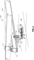
- FIG. 2 illustrates the L-foot of FIG. 1 used in a solar panel racking system 120 that is rail-based.
- a rail-less mid clamp assembly 102 secures solar panel 103 to the L-foot 101.
- One or more threaded roof fasteners secure the L-foot 101 to the roof 104.
- Performance requirements such as holding strength or lift force resistance, can help the installer determine the appropriate number of roof fasteners to secure the L-foot 101 to the roof.
- first threaded roof fastener 105 shows a first threaded roof fastener 105, second threaded roof fastener 106, third threaded roof fastener 107, fourth threaded roof fastener 108, fifth threaded roof fastener 109, and sixth threaded roof fastener 110, securing the L-foot 101 to roof 104.
- end clamp 111 secures solar panel 103 to rail 112.
- the L-foot adapter 113 in combination with threaded fastener 114, secures rail 112 to the L-foot 101.
- Loosening the threaded fastener 114 allows the threaded fastener 114 to move up and down along the slot-shaped aperture 101a of the L-foot 101.
- loosening the threaded fastener 114 allows it to move up and down along the slot-shaped aperture 101a of the L-foot 101. This causes the solar panel 103 and the rail-less mid clamp assembly 102 to move up or down with respect to the roof 104.
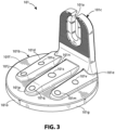
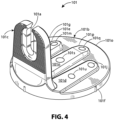
- FIGS. 3-11 illustrate a front isometric view, rear isometric view, front view, rear view, right side view, left side view, bottom view, top view, and a second top view, respectively of the L-foot 101.
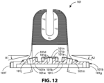
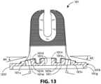
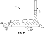
- FIGS. 12 , 13 , and 14 are section views along the base 101b of the L-foot 101.
- FIGS. 12 illustrates a section view taken along section lines 12-12 in FIG. 10 .
- FIG. 13 illustrates a section view taken along section lines 13-13 of FIG. 10 .
- FIG. 14 illustrates a section view taken along section lines 14-14 in FIG. 11 .
- the L-foot includes a base 101b and a riser 101c extending upward from the base 101b. Together, the base 101b and the riser 101c form a substantially L-shape bracket.
- the base 101b includes a first raised stiffener 101d, and a second raised stiffener 101e, each extending obliquely upward toward each other from opposite sides of the base 101b, and each extending lengthwise along the base 101b. Lengthwise, for the purposes of this disclosure, means in the direction from front-to-back or back-to-front of the base 101b.
- the first raised stiffener 101d extends obliquely upward away from a first side 101f and the second raised stiffener 101e extends obliquely upward away from a second side 101g.
- the first raised stiffener 101d extends obliquely upward at an angle A1 with respect to the horizon.
- the second raised stiffener extends obliquely upward at an angle A2 with respect to the horizon.
- the top and the bottom of the base 101b are parallel to the horizon.
- the inventors built and tested the L-foot 101 with the angle A1 equal to 15° and the angle A2 equal to 15°.
- angle A1 and angle A2 can each vary from 10° to 45° angle range and still provide sufficient holding strength through the roof deck, and allow the installer greater access to threaded roof fasteners with their installation tools.
- the first raised stiffener 101d and the second raised stiffener 101e each have a widthwise wedge-shaped profile.
- widthwise with respect to the base 101b refers to the direction between the first side 101f and the second side 101g.
- the first raised stiffener 101d has a first widthwise wedge-shaped cross section 101h.
- the second raised stiffener 101e has a second widthwise wedge-shaped cross section 101i.
- the first widthwise wedge-shaped cross section 101h extends upward away from the first side 101f toward the center of the base 101b.
- the second widthwise wedge-shaped cross section 101i extends upward away from the second side 101g and toward the center of the base 101b.
- base 101b includes a first aperture 101j.
- the first aperture 101j extends perpendicularly through the first raised stiffener 101d and obliquely through the bottom 101k of the base 101b.
- the base 101b includes a second aperture 101m.
- the second aperture 101m extends perpendicularly through the second raised stiffener 101e and obliquely through the bottom 101k of the base 101b toward the first aperture 101j.
- FIG. 9 also shows the first aperture 101j and the second aperture 101m extending through the bottom 101k of the base 101b toward each other.
- the base 101b also includes a third raised stiffener 101n extending upward from and lengthwise along the base 101b.
- the third raised stiffener 101n is positioned between the first raised stiffener 101d and the second raised stiffener 101e.
- the base 101b includes a front side 101o positioned opposite the riser 101c.
- the third raised stiffener 101n includes an end 101p positioned distal to (i.e., the end 101p is away from) the riser 101c.
- the end 101p extends obliquely upward away from the front side 101o toward the riser 101c. Referring to FIG. 14 , the end 101p extends obliquely upward at an angle A9 with respect to the horizon.
- the main body of the third raised stiffener, the top of the base 101b, and the bottom 101k of the base 102b are parallel to the horizon.
- the end 101p of the third raised stiffener 101n has a lengthwise wedge-shaped profile.
- the lengthwise wedge-shaped profile extends from the base of the wedge to the top of the wedge and away from the front side 101o and toward the riser 101c.
- FIG. 14 illustrates the end 101p with a lengthwise wedge-shaped cross section 101t.
- a third aperture 101q extends perpendicularly through the end 101p and obliquely through the bottom 101k of the base 101b toward the riser 101c.
- the third raised stiffener 101n includes a main body that is substantially planar and parallel to a seating plane 101r of the base 101b. The main body of the third raised stiffener 101n can extend from the riser 101c to the end 101p, as illustrated.
- a fourth aperture 101s extends perpendicularly through the main body of the third raised stiffener 101n and perpendicularly through the bottom 101k of the base 101b.
- FIGS. 3-5 , and 9-11 also illustrate the third aperture 101q and the fourth aperture 101s (not shown in FIG. 5 ).
- FIGS. 12 and 13 illustrate the third raised stiffener 101n in front cross section.
- FIG. 12 illustrates a front cross section of the third aperture 101q extending through the end 101p.
- FIG. 13 illustrates a front cross section of the fourth aperture 101s extending through the main body of the third raised stiffener 101n.
- the first raised stiffener 101d can include additional apertures. These apertures can accept additional threaded roof fasteners to provide the solar panel assembly with greater holding strength and resistance to wind and lift forces.
- the first raised stiffener 101d can include a fifth aperture 101u and the second raised stiffener can include a sixth aperture 101v.
- FIGS. 4 and 8 illustrates the fifth aperture 101u in rear isometric view and side view, respectively.
- FIG. 7 illustrates the sixth aperture 101v in side view.
- FIG. 9 illustrates the fifth aperture 101u and the sixth aperture 101v in bottom view. Referring to FIG.
- the fifth aperture 101u extends perpendicularly through the first raised stiffener 101d and obliquely through a bottom 101k of the base 101b.
- the sixth aperture 101v extends perpendicularly through the second raised stiffener 101e and obliquely through the bottom 101k of the base 101b toward the first raised stiffener 101d.
- a blind aperture, or recess 101w extends upward from the bottom 101k of the base 101b.
- the recess 101w can receive and seat a gasket.
- FIG. 15 illustrates a gasket 115, exploded away from the L-foot 101.
- the L-foot 101 receives and seats the gasket 115 in the bottom 101k of the base 101b.
- FIGS. 16 and 17 illustrate along the cross sections 12-12 of FIG. 10 and 14-14 of FIG. 11 , respectively, the L-foot 101, gasket 115, and various threaded roof fasteners attached to a roof 104.
- FIG. 16 illustrates the L-foot 101 with the first threaded roof fastener 105 extending through the first aperture 101j.
- the first threaded roof fastener 105 extends perpendicularly through the top of the first raised stiffener 101d, and extends obliquely through the base 101b of the L-foot 101, the gasket 115, the roof cover 104a, and the roof deck 104b.
- the second threaded roof fastener 106 extends perpendicularly through the second aperture 101m.
- the second threaded roof fastener 106 extends obliquely through the bottom of the base 101b, the gasket 115, the roof cover 104a, and the roof deck 104b toward the first threaded roof fastener 105.
- the first threaded roof fastener 105 makes an oblique angle of 90°-A1.
- the first threaded roof fastener 105 makes an oblique angle of 90°-A2.
- FIG. 12 shows angle A1 and angle A2.
- FIG. 17 illustrates the third threaded roof fastener 107 extending perpendicularly through the third aperture 101q.
- the third threaded roof fastener 107 extends obliquely at an angle of 90°-A3.
- FIG. 14 shows angle A3.
- the third threaded roof fastener 107 extends inward away from the front side 101o through the gasket 115, the roof cover 104a, and the roof deck 104b.
- the first threaded roof fastener 105, and the fifth threaded roof fastener 109 extend obliquely and inwardly below the base 101b and through the bottom of the roof deck 104b.
- the fourth threaded roof fastener 108 passes perpendicularly downward through the third raised stiffener 101n, the gasket 115, the roof cover 104a, and roof deck 104b. Referring to FIG. 16 , the third threaded roof fastener 107 extends into the end 101p of the third raised stiffener 101n and through the roof deck 104b.
- brackets and devices for mounting solar panels to roofs This disclosure provides examples of devices, components, and configurations to help the reader understand the described general principles. The following are examples of how different components, structures, and features can be varied while still adhering to the general principles.
- the base 101b as illustrated in FIGS. 3 , 4 , and 9-11 is a circular cylinder.
- the riser of FIGS. 3-6 , 10 , and 11 is of a typical height
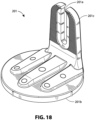
- the riser 201c of the L-foot 201 of FIG. 18 is taller while the structure of the base 201b remains the same as described for FIGS. 3-14 .
- the riser 101c shown in various views in FIGS. 3-6 , 10 , and 11 includes slot-shaped aperture 101a that is open at the top of the riser.
- the slot-shaped aperture can alternatively be closed on both ends.
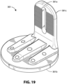
- FIG. 19 illustrates the L-foot 301 that includes a base 301b with a similar structure as base 101b of FIG. 3 .
- Riser 301c has a closed slot shaped aperture, the slot-shaped aperture 301a.
- the riser 101c can have a rectangular, or triangular face profile.
- first threaded roof fastener 105, second threaded roof fastener 106, the third threaded roof fastener 107, the fourth threaded roof fastener 108, the fifth threaded roof fastener 109, and the sixth threaded roof fastener 110 as illustrated in FIGS. 1 and 2 are hex-head decking screws with a hexagonal socket.
- This screw head style is compatible with common power or hand tools.
- the installer could choose threaded roof fasteners with other head styles that suits either power tools or hand tools.
- the installer could use a hex-head cap screw, also known as a hex-head bolt or hex-head screw.
- Other examples include pan-head, button-head, or round head screws. These can include hexagonal sockets, Phillips head sockets, slotted sockets, hi-torque sockets, square sockets, Robertson head sockets, or Torx head sockets. They can also include various custom or off-the-shelf security head screws.
- the threaded roof fasteners illustrated are deck screws with built-in seals. They could alternatively be lag bolts with sealing washers. The inventors envision using any screw or bolt that can perform the function specified in this specification, provide a water tight seal, and provide enough holding strength to perform to the typical environmental conditions expected for a solar panel array installation.
- FIGS. 3 , 10 , and 11 illustrate the first raised stiffener 101d, the second raised stiffener 101e, and the third raised stiffener 101n, each with two apertures.
- the width of the raised stiffeners can be widened or narrowed to accommodate threaded roof fasteners with wider or narrower bodies and wider or narrower heads.
- the number of apertures and their associated fasteners depends on several factors. These include anticipated environmental conditions, such as wind loads, roof structural factors such as roof decking materials and thicknesses, or regulatory considerations, such as regional or national rules governing solar panel installation.
- the L-foot 101 of FIGS. 1-17 , the L-foot 201 of FIG. 18 , and the L-foot 301 of FIG. 19 can be made of any material that has sufficient structural strength to support solar panels and their associated racking systems to a roof and to withstand expected environmental conditions such as wind loads, temperature variations, and ultra-violet (UV) light from the sun.
- suitable materials include aluminum, steel, or thermoplastics, or thermoset polyurethanes.
- An aluminum or steel L-foot could be formed by casting, CNC milling, or 3D printing.
- the riser 101c and the base 101b could be separately formed and then joined by fasteners or by welding.
- the riser 101c or the base 101b could be stamped, cast, or extruded and then finished with secondary operations.
- a thermoplastic L-foot could be molded or 3D printed.
- L-foot may be electrically conductive.
- electrically conductive materials suitable for the L-foot include metals, or plastics with conductive properties. For example, aluminum and steel conduct electricity and have sufficient structural strength to withstand expected environmental conditions. Depending on the region and their regulatory requirements, thermoset polyurethane or thermoplastics with embedded metal salts or other conductive materials may have sufficient strength and electrical conductivity.
- the L-foot could have more or fewer apertures for receiving roof fasteners and the position of the apertures can change. For example, for some regions, an L-foot adapter with two apertures or three apertures might be sufficient. Referring to FIG. 3 , a two-aperture example, might eliminate the first aperture 101j, the second aperture 101m, the third aperture 101q, and the fourth aperture 101s but leave the fifth aperture 101u and the sixth aperture 101v. A three-aperture example might leave the third aperture 101q, the fifth aperture 101u, and the sixth aperture 101v.
- the L-foot could have their apertures arranged along their respective stiffeners to meet specific design parameters. For example, for the three-aperture example, the apertures could be arranged to form an equilateral triangle to increase stability.
- the installer might opt to install threaded roof fasteners in some of the apertures while not in others.
- FIG. 1 shows six threaded roof fasteners securing the L-foot 101 to roof 104.
- An installer could choose to use fewer threaded roof fasteners if doing so meets the installation requirements of their region.
- the installer might opt to install third threaded roof fastener 107, fifth threaded roof fastener 109, and sixth threaded roof fastener 110 and not the others.
- the installer could fill the remaining holes with a sealant, such as silicone.
- FIG. 3 shows the top surface of the first aperture 101j and the fifth aperture 101u of the first raised stiffener 101d in the same plane.
- the second aperture 101m and the sixth aperture 101v of the second raised stiffener 101e lie in the same plane. Viewing these apertures in cross section, referring to FIGS. 12 and 13 , angle A1 ( FIG. 12 ) equals angle A4 ( FIG. 13 ).
- Angle A2 ( FIG. 13 ) equals angle A5 ( FIG. 13 ).
Landscapes
- Engineering & Computer Science (AREA)
- Architecture (AREA)
- Civil Engineering (AREA)
- Structural Engineering (AREA)
- Physics & Mathematics (AREA)
- Life Sciences & Earth Sciences (AREA)
- Sustainable Development (AREA)
- Sustainable Energy (AREA)
- Thermal Sciences (AREA)
- Chemical & Material Sciences (AREA)
- Combustion & Propulsion (AREA)
- Mechanical Engineering (AREA)
- General Engineering & Computer Science (AREA)
- Roof Covering Using Slabs Or Stiff Sheets (AREA)
Applications Claiming Priority (1)
| Application Number | Priority Date | Filing Date | Title |
|---|---|---|---|
| US18/101,111 US11750143B1 (en) | 2023-01-24 | 2023-01-24 | Bracket and devices for mounting solar panels to roofs |
Publications (1)
| Publication Number | Publication Date |
|---|---|
| EP4407864A1 true EP4407864A1 (de) | 2024-07-31 |
Family
ID=87882576
Family Applications (1)
| Application Number | Title | Priority Date | Filing Date |
|---|---|---|---|
| EP24150589.0A Withdrawn EP4407864A1 (de) | 2023-01-24 | 2024-01-05 | Halterung und vorrichtungen zur montage eines solarpaneels auf dächern |
Country Status (2)
| Country | Link |
|---|---|
| US (1) | US11750143B1 (de) |
| EP (1) | EP4407864A1 (de) |
Families Citing this family (25)
| Publication number | Priority date | Publication date | Assignee | Title |
|---|---|---|---|---|
| US9611652B2 (en) | 2011-02-25 | 2017-04-04 | Dustin M. M. Haddock | Mounting device for building surfaces having elongated mounting slot |
| US20130168525A1 (en) | 2011-12-29 | 2013-07-04 | Dustin M.M. Haddock | Mounting device for nail strip panels |
| WO2018023016A1 (en) | 2016-07-29 | 2018-02-01 | Haddock Dustin M M | Trapezoidal rib mounting bracket with flexible legs |
| AU2018348090B2 (en) | 2017-10-09 | 2021-11-18 | Rmh Tech Llc | Rail assembly with invertible side-mount adapter for direct and indirect mounting applications |
| US10903785B2 (en) | 2018-03-21 | 2021-01-26 | Rmh Tech Llc | PV module mounting assembly with clamp/standoff arrangement |
| CN113412396A (zh) | 2018-12-14 | 2021-09-17 | Rmh技术有限责任公司 | 用于钉带面板的安装装置 |
| JP7319150B2 (ja) * | 2019-09-12 | 2023-08-01 | ニチハ株式会社 | 建築用ブラケット、建物壁構造、および板材施工方法 |
| EP4034720A4 (de) | 2019-09-23 | 2023-10-25 | Ecofasten Solar, LLC | Dachbefestigungssystem und -vorrichtung |
| CN115917095A (zh) | 2020-03-16 | 2023-04-04 | Rmh技术有限责任公司 | 用于金属屋顶的安装装置 |
| BR112023000401A2 (pt) | 2020-07-09 | 2023-01-31 | Rmh Tech Llc | Sistema, dispositivo e método de montagem |
| US11296648B1 (en) * | 2021-05-14 | 2022-04-05 | Sunmodo Corporation | Solar panel racking system and devices for the same |
| US11808042B2 (en) | 2021-05-21 | 2023-11-07 | Unirac Inc. | Attachment bracket apparatus |
| US12474014B2 (en) * | 2021-05-21 | 2025-11-18 | Unirac, Inc. | Attachment bracket apparatus |
| US12483185B2 (en) | 2021-09-09 | 2025-11-25 | Rmh Tech Llc | Torque actuated rail assembly |
| USD1075493S1 (en) | 2022-07-06 | 2025-05-20 | Rmh Tech Llc | Clamp for a photovoltaic module mounting assembly |
| US12519418B2 (en) | 2022-07-06 | 2026-01-06 | Rmh Tech Llc | PV module mounting assembly with clamp / standoff arrangement |
| JP2024059301A (ja) * | 2022-10-18 | 2024-05-01 | イーソルテック合同会社 | 架台の施工方法 |
| USD1113406S1 (en) | 2023-04-14 | 2026-02-17 | Rmh Tech Llc | Mounting device |
| CN121358993A (zh) | 2023-04-14 | 2026-01-16 | Rmh技术有限责任公司 | 用于金属面板的安装装置 |
| USD1109686S1 (en) | 2023-08-10 | 2026-01-20 | Rmh Tech Llc | Mount for a component of a photovoltaic assembly |
| US11929704B1 (en) * | 2023-09-27 | 2024-03-12 | Sunmodo Corporation | Method and system for securing a solar panel to a tile roof |
| US12009774B1 (en) | 2023-12-29 | 2024-06-11 | Sunmodo Corporation | L-foot adapter for rail-based solar panel racking systems |
| US12149200B1 (en) | 2024-07-03 | 2024-11-19 | Sunmodo Corporation | Railless mounting system and devices for attaching solar modules to roofs |
| US12231076B1 (en) | 2024-09-04 | 2025-02-18 | Sunmodo Corporation | Rail-less mounting system and devices for attaching solar modules to roofs |
| US12286994B1 (en) * | 2024-09-09 | 2025-04-29 | Sunmodo Corporation | Railless mounting devices for securing solar modules to roofs |
Citations (4)
| Publication number | Priority date | Publication date | Assignee | Title |
|---|---|---|---|---|
| US20110272545A1 (en) * | 2010-05-07 | 2011-11-10 | Jun Liu | Bracket Assembly for Mounting Rooftop Objects |
| US10601360B2 (en) * | 2017-09-08 | 2020-03-24 | Unirac Inc. | Replacement tile mount for mounting solar panels on tile roofs |
| US10663195B2 (en) * | 2015-07-29 | 2020-05-26 | Ironridge, Inc. | Tile roof mount |
| US20220372762A1 (en) * | 2021-05-21 | 2022-11-24 | Unirac, Inc. | Attachment bracket apparatus |
Family Cites Families (48)
| Publication number | Priority date | Publication date | Assignee | Title |
|---|---|---|---|---|
| US712824A (en) | 1902-03-04 | 1902-11-04 | Harvey C Masland | Holder for brushes and drinking-glasses. |
| US4344593A (en) | 1980-09-15 | 1982-08-17 | Canto Gabriel F | Support for horizontal pipe or the like |
| USD278111S (en) | 1982-09-28 | 1985-03-26 | Albert Mazeika | Frame corner retainer |
| JPH0790296B2 (ja) | 1985-03-26 | 1995-10-04 | スズキ株式会社 | ブラケット |
| USD312382S (en) | 1987-03-23 | 1990-11-27 | Holdem Company | Anchor bolt holder for concrete construction or similar use |
| US4835935A (en) | 1987-12-10 | 1989-06-06 | Murphy Wesley T | Support structure including right angle stud bracket |
| USD357400S (en) | 1993-08-03 | 1995-04-18 | Isaac Sachs | Connector element |
| US5720571A (en) | 1994-12-22 | 1998-02-24 | Super Stud Building Products, Inc. | Deflection slide clip |
| DE29718172U1 (de) | 1997-10-14 | 1997-11-27 | GH-Baubeschläge Hartmann GmbH, 32549 Bad Oeynhausen | Winkelverbinder |
| US6213679B1 (en) | 1999-10-08 | 2001-04-10 | Super Stud Building Products, Inc. | Deflection slide clip |
| FR2876168A1 (fr) | 2004-10-04 | 2006-04-07 | Dacri Soc Par Actions Simplifi | Perfectionnement aux pattes de fixation en forme generale d'equerre |
| USD540367S1 (en) | 2005-01-21 | 2007-04-10 | Csav, Inc. | Universal projector mount |
| USD584597S1 (en) | 2005-11-23 | 2009-01-13 | Wilbur Menard | Structure anchor |
| GB2457714A (en) | 2008-02-22 | 2009-08-26 | Simpson Strong Tie Co Inc | One-piece angle bracket for fastening a first construction element to a second construction element |
| GB0907951D0 (en) | 2009-05-08 | 2009-06-24 | Keystone Lintels Ltd | A fixture for a window |
| AU2009100911C4 (en) | 2009-09-10 | 2015-08-27 | Surefoot Ip Holdings Pty Ltd | PostFixer |
| FR2970284B1 (fr) | 2011-01-12 | 2013-01-04 | H L R | Patte et procede de fixation par vissage d'un dormant de menuiserie |
| US20120187267A1 (en) * | 2011-01-26 | 2012-07-26 | JAC-Rack, Inc. | Adjustable mounting bracket for a photovoltaic panel frame system |
| AU337799S (en) | 2011-06-28 | 2011-07-25 | Surefoot Systems International Ltd | Footing plate |
| AU337788S (en) | 2011-06-28 | 2011-07-25 | Surefoot Systems International Ltd | Footing plate |
| EP2726687B8 (de) | 2011-06-28 | 2018-02-14 | Surefoot Systems International Limited | Verbesserte basisplatten |
| AU338367S (en) | 2011-08-05 | 2011-09-01 | Surefoot Systems International Ltd | Footing plate |
| KR20130039030A (ko) | 2011-10-11 | 2013-04-19 | 양내문 | 수직벽체 알루미늄 폼을 이용한 슬래브용 클린 캡 구조체 |
| USD725999S1 (en) | 2013-11-19 | 2015-04-07 | Chia-Lun Wu | Hanging bracket for cleaning supplies |
| US8938932B1 (en) | 2013-12-13 | 2015-01-27 | Quality Product Llc | Rail-less roof mounting system |
| USD727395S1 (en) | 2014-01-03 | 2015-04-21 | Eyesee360, Inc. | Panoramic camera mounting bracket |
| US9680409B2 (en) * | 2014-01-29 | 2017-06-13 | D Three Enterprises, Llc | Adjustable combined flashing and mounting apparatus and method of mounting to be used therewith |
| US9577571B2 (en) * | 2015-04-17 | 2017-02-21 | Moti Atia | Solar panel mounting apparatus with enhanced strength |
| USD818517S1 (en) | 2015-08-04 | 2018-05-22 | Steven James Szarawarski | Carry strap bracket for a camera |
| US10277162B1 (en) * | 2016-08-16 | 2019-04-30 | Moti Atia | Mounting apparatus to secure a solar panel rail to stone-coated metal tile roofs |
| US10840850B1 (en) * | 2016-08-16 | 2020-11-17 | Moti Atia | Mounting apparatus to secure solar panel rails to asphalt shingle roofs |
| US10998847B2 (en) | 2016-08-23 | 2021-05-04 | Pegasus Solar Inc. | Solar mounting assemblies |
| CN108071195A (zh) * | 2016-11-16 | 2018-05-25 | 江苏晨科新能源有限公司 | 一种彩钢瓦夹具 |
| US10633858B2 (en) | 2016-11-21 | 2020-04-28 | Specified Technologies Inc. | Prefabricated curtain wall assembly |
| US10447197B2 (en) * | 2016-12-14 | 2019-10-15 | Tecsi Solar, Inc. | Systems and methods for mounting roof-mounted photovoltaic arrays including flashing and adhesive pads |
| US10781587B2 (en) | 2016-12-14 | 2020-09-22 | Solsera, Inc. | Structural attachment sealing system |
| USD833851S1 (en) | 2017-02-22 | 2018-11-20 | HumanCentric Ventures LLC | VESA mount adapter bracket |
| CN206559283U (zh) | 2017-02-28 | 2017-10-13 | 江阴市泰坦光伏材料有限公司 | 光伏支架l脚套装组件 |
| USD884302S1 (en) | 2018-12-14 | 2020-05-12 | Robert A. Azzaro | Trash can lid fastener |
| US11739785B2 (en) | 2019-04-01 | 2023-08-29 | Unirac Inc. | Trim attachment assembly for mounting solar panel equipment |
| JP7319150B2 (ja) | 2019-09-12 | 2023-08-01 | ニチハ株式会社 | 建築用ブラケット、建物壁構造、および板材施工方法 |
| USD909853S1 (en) | 2019-09-19 | 2021-02-09 | Sunmodo Corporation | Roof mount attachment for mounting solar panels |
| MX421218B (es) | 2019-11-18 | 2025-02-10 | Ironridge Inc | Ensamble de montaje de soporte y tapajuntas para asegurar guias de rieles de paneles solares en techos de tejas. |
| CN110912499A (zh) * | 2019-12-19 | 2020-03-24 | 朱国浩 | 一种用于安装太阳能光伏组件的挂钩 |
| US11152889B1 (en) | 2020-03-12 | 2021-10-19 | Sunrun Inc. | Mount assemblies with chemical flashings |
| USD962039S1 (en) | 2020-07-20 | 2022-08-30 | CKnapp Sales, Inc. | Mounting bracket |
| CA3208856A1 (en) | 2021-02-03 | 2022-08-11 | Unirac Inc. | Roof interface with sealant injection ports |
| US11296648B1 (en) | 2021-05-14 | 2022-04-05 | Sunmodo Corporation | Solar panel racking system and devices for the same |
-
2023
- 2023-01-24 US US18/101,111 patent/US11750143B1/en active Active
-
2024
- 2024-01-05 EP EP24150589.0A patent/EP4407864A1/de not_active Withdrawn
Patent Citations (4)
| Publication number | Priority date | Publication date | Assignee | Title |
|---|---|---|---|---|
| US20110272545A1 (en) * | 2010-05-07 | 2011-11-10 | Jun Liu | Bracket Assembly for Mounting Rooftop Objects |
| US10663195B2 (en) * | 2015-07-29 | 2020-05-26 | Ironridge, Inc. | Tile roof mount |
| US10601360B2 (en) * | 2017-09-08 | 2020-03-24 | Unirac Inc. | Replacement tile mount for mounting solar panels on tile roofs |
| US20220372762A1 (en) * | 2021-05-21 | 2022-11-24 | Unirac, Inc. | Attachment bracket apparatus |
Also Published As
| Publication number | Publication date |
|---|---|
| US11750143B1 (en) | 2023-09-05 |
Similar Documents
| Publication | Publication Date | Title |
|---|---|---|
| US11750143B1 (en) | Bracket and devices for mounting solar panels to roofs | |
| US11757400B1 (en) | Devices for mounting solar PV panels to roofs and other mounting structures | |
| US10365017B2 (en) | Self-adjusting end clamp | |
| US11283396B2 (en) | Solar panel mounting system and method | |
| AU2009357024B2 (en) | Auxiliary members | |
| US10243507B2 (en) | End clamp for mounting solar module to rail | |
| EP2169139B1 (de) | Befestigungsstruktur für ein solarbatteriemodul, rahmen für das solarbatteriemodul und befestigungselement | |
| US6672018B2 (en) | Solar module mounting method and clip | |
| US10103688B2 (en) | Systems and methods for improved installation and grounding of photovoltaic assemblies | |
| US10883271B2 (en) | Roof mounting bracket | |
| EP3426934B1 (de) | Halteklammeranordnungen und -verfahren | |
| US10673374B2 (en) | Solar panel module mounting bracket | |
| US11811356B2 (en) | Method for installing solar cell module | |
| US9166522B1 (en) | Solar panel mounting assembly | |
| US11228274B2 (en) | Panel mounting bracket with grounding mid-clamp and related methods | |
| US20250317095A1 (en) | Solar Module Skirt Assembly | |
| US10812012B2 (en) | Hinging inverted seam module mounting system | |
| WO2016204941A1 (en) | Self-locking photovoltaic module mounting system | |
| US20180062559A1 (en) | Systems and methods for improved installation of photovoltaic assemblies | |
| ES2928409T3 (es) | Dispositivo de montaje para montar paneles solares en una estructura | |
| JP2017048506A (ja) | 折板屋根用取付金具 | |
| AU2022201695B2 (en) | Mounting bracket assemblies and methods | |
| KR102081387B1 (ko) | 태양광모듈 설치용 고정장치 |
Legal Events
| Date | Code | Title | Description |
|---|---|---|---|
| PUAI | Public reference made under article 153(3) epc to a published international application that has entered the european phase |
Free format text: ORIGINAL CODE: 0009012 |
|
| STAA | Information on the status of an ep patent application or granted ep patent |
Free format text: STATUS: THE APPLICATION HAS BEEN PUBLISHED |
|
| STAA | Information on the status of an ep patent application or granted ep patent |
Free format text: STATUS: REQUEST FOR EXAMINATION WAS MADE |
|
| AK | Designated contracting states |
Kind code of ref document: A1 Designated state(s): AL AT BE BG CH CY CZ DE DK EE ES FI FR GB GR HR HU IE IS IT LI LT LU LV MC ME MK MT NL NO PL PT RO RS SE SI SK SM TR |
|
| 17P | Request for examination filed |
Effective date: 20240628 |
|
| RBV | Designated contracting states (corrected) |
Designated state(s): AL AT BE BG CH CY CZ DE DK EE ES FI FR GB GR HR HU IE IS IT LI LT LU LV MC ME MK MT NL NO PL PT RO RS SE SI SK SM TR |
|
| GRAP | Despatch of communication of intention to grant a patent |
Free format text: ORIGINAL CODE: EPIDOSNIGR1 |
|
| STAA | Information on the status of an ep patent application or granted ep patent |
Free format text: STATUS: GRANT OF PATENT IS INTENDED |
|
| INTG | Intention to grant announced |
Effective date: 20241126 |
|
| STAA | Information on the status of an ep patent application or granted ep patent |
Free format text: STATUS: THE APPLICATION IS DEEMED TO BE WITHDRAWN |
|
| 18D | Application deemed to be withdrawn |
Effective date: 20250327 |