EP4407832A1 - Vorrichtung und verfahren zur erstellung eines betriebsplans für ein batteriesystem mit neu installierten batterien - Google Patents
Vorrichtung und verfahren zur erstellung eines betriebsplans für ein batteriesystem mit neu installierten batterien Download PDFInfo
- Publication number
- EP4407832A1 EP4407832A1 EP23868341.1A EP23868341A EP4407832A1 EP 4407832 A1 EP4407832 A1 EP 4407832A1 EP 23868341 A EP23868341 A EP 23868341A EP 4407832 A1 EP4407832 A1 EP 4407832A1
- Authority
- EP
- European Patent Office
- Prior art keywords
- batteries
- discharge
- amount
- augmentation
- discharge energy
- Prior art date
- Legal status (The legal status is an assumption and is not a legal conclusion. Google has not performed a legal analysis and makes no representation as to the accuracy of the status listed.)
- Pending
Links
Images


Classifications
-
- H—ELECTRICITY
- H02—GENERATION; CONVERSION OR DISTRIBUTION OF ELECTRIC POWER
- H02J—ELECTRIC POWER NETWORKS; CIRCUIT ARRANGEMENTS OR SYSTEMS FOR SUPPLYING OR DISTRIBUTING ELECTRIC POWER; SYSTEMS FOR STORING ELECTRIC ENERGY
- H02J7/00—Circuit arrangements for charging or discharging batteries or for supplying loads from batteries
- H02J7/50—Circuit arrangements for charging or discharging batteries or for supplying loads from batteries acting upon multiple batteries simultaneously or sequentially
- H02J7/585—Sequential battery discharge in systems with a plurality of batteries
-
- G—PHYSICS
- G01—MEASURING; TESTING
- G01R—MEASURING ELECTRIC VARIABLES; MEASURING MAGNETIC VARIABLES
- G01R31/00—Arrangements for testing electric properties; Arrangements for locating electric faults; Arrangements for electrical testing characterised by what is being tested not provided for elsewhere
- G01R31/36—Arrangements for testing, measuring or monitoring the electrical condition of accumulators or electric batteries, e.g. capacity or state of charge [SoC]
- G01R31/367—Software therefor, e.g. for battery testing using modelling or look-up tables
-
- H—ELECTRICITY
- H02—GENERATION; CONVERSION OR DISTRIBUTION OF ELECTRIC POWER
- H02J—ELECTRIC POWER NETWORKS; CIRCUIT ARRANGEMENTS OR SYSTEMS FOR SUPPLYING OR DISTRIBUTING ELECTRIC POWER; SYSTEMS FOR STORING ELECTRIC ENERGY
- H02J7/00—Circuit arrangements for charging or discharging batteries or for supplying loads from batteries
- H02J7/34—Parallel operation in networks using both storage and other DC sources, e.g. providing buffering
- H02J7/342—The other DC source being a battery actively interacting with the first one, i.e. battery to battery charging
-
- G—PHYSICS
- G01—MEASURING; TESTING
- G01R—MEASURING ELECTRIC VARIABLES; MEASURING MAGNETIC VARIABLES
- G01R31/00—Arrangements for testing electric properties; Arrangements for locating electric faults; Arrangements for electrical testing characterised by what is being tested not provided for elsewhere
- G01R31/36—Arrangements for testing, measuring or monitoring the electrical condition of accumulators or electric batteries, e.g. capacity or state of charge [SoC]
- G01R31/392—Determining battery ageing or deterioration, e.g. state of health
-
- H—ELECTRICITY
- H02—GENERATION; CONVERSION OR DISTRIBUTION OF ELECTRIC POWER
- H02J—ELECTRIC POWER NETWORKS; CIRCUIT ARRANGEMENTS OR SYSTEMS FOR SUPPLYING OR DISTRIBUTING ELECTRIC POWER; SYSTEMS FOR STORING ELECTRIC ENERGY
- H02J3/00—Circuit arrangements for AC mains or AC distribution networks
- H02J3/28—Arrangements for balancing of the load in networks by storage of energy
-
- H—ELECTRICITY
- H02—GENERATION; CONVERSION OR DISTRIBUTION OF ELECTRIC POWER
- H02J—ELECTRIC POWER NETWORKS; CIRCUIT ARRANGEMENTS OR SYSTEMS FOR SUPPLYING OR DISTRIBUTING ELECTRIC POWER; SYSTEMS FOR STORING ELECTRIC ENERGY
- H02J7/00—Circuit arrangements for charging or discharging batteries or for supplying loads from batteries
- H02J7/80—Circuit arrangements for charging or discharging batteries or for supplying loads from batteries including monitoring or indicating arrangements
- H02J7/84—Control of state of health [SOH]
-
- H—ELECTRICITY
- H02—GENERATION; CONVERSION OR DISTRIBUTION OF ELECTRIC POWER
- H02J—ELECTRIC POWER NETWORKS; CIRCUIT ARRANGEMENTS OR SYSTEMS FOR SUPPLYING OR DISTRIBUTING ELECTRIC POWER; SYSTEMS FOR STORING ELECTRIC ENERGY
- H02J7/00—Circuit arrangements for charging or discharging batteries or for supplying loads from batteries
- H02J7/90—Regulation of charging or discharging current or voltage
- H02J7/92—Regulation of charging or discharging current or voltage with prioritisation of loads or sources
-
- H—ELECTRICITY
- H02—GENERATION; CONVERSION OR DISTRIBUTION OF ELECTRIC POWER
- H02J—ELECTRIC POWER NETWORKS; CIRCUIT ARRANGEMENTS OR SYSTEMS FOR SUPPLYING OR DISTRIBUTING ELECTRIC POWER; SYSTEMS FOR STORING ELECTRIC ENERGY
- H02J7/00—Circuit arrangements for charging or discharging batteries or for supplying loads from batteries
- H02J7/90—Regulation of charging or discharging current or voltage
- H02J7/933—Regulation of charging or discharging current or voltage the cycle being controlled or terminated in response to electric parameters
-
- H—ELECTRICITY
- H02—GENERATION; CONVERSION OR DISTRIBUTION OF ELECTRIC POWER
- H02J—ELECTRIC POWER NETWORKS; CIRCUIT ARRANGEMENTS OR SYSTEMS FOR SUPPLYING OR DISTRIBUTING ELECTRIC POWER; SYSTEMS FOR STORING ELECTRIC ENERGY
- H02J7/00—Circuit arrangements for charging or discharging batteries or for supplying loads from batteries
- H02J7/50—Circuit arrangements for charging or discharging batteries or for supplying loads from batteries acting upon multiple batteries simultaneously or sequentially
-
- Y—GENERAL TAGGING OF NEW TECHNOLOGICAL DEVELOPMENTS; GENERAL TAGGING OF CROSS-SECTIONAL TECHNOLOGIES SPANNING OVER SEVERAL SECTIONS OF THE IPC; TECHNICAL SUBJECTS COVERED BY FORMER USPC CROSS-REFERENCE ART COLLECTIONS [XRACs] AND DIGESTS
- Y02—TECHNOLOGIES OR APPLICATIONS FOR MITIGATION OR ADAPTATION AGAINST CLIMATE CHANGE
- Y02E—REDUCTION OF GREENHOUSE GAS [GHG] EMISSIONS, RELATED TO ENERGY GENERATION, TRANSMISSION OR DISTRIBUTION
- Y02E60/00—Enabling technologies; Technologies with a potential or indirect contribution to GHG emissions mitigation
- Y02E60/10—Energy storage using batteries
Definitions
- the present invention relates to an apparatus and method for establishing an operation plan of a battery system, and more particularly, to an apparatus and method for establishing an operation plan of a battery system which is operated by augmenting old batteries with new batteries.
- An energy storage system relates to renewable energy, batteries that store electric power, and an existing power grid. Recently, as research into smart grid and renewable energy is expanding and the efficiency and the stability of the power system are emphasized, a demand for energy storage systems for power supply and demand control, and power quality improvement is increasing. Depending on a purpose of use, energy storage systems may have different output and capacity. In order to configure a large-capacity energy storage system, a plurality of battery systems may be connected to provide the large-capacity energy storage system.
- energy storage systems are installed at a specific site and operate for a long period of time.
- a larger number of batteries than necessary must be initially installed in consideration of the deterioration of battery performance over time.
- an energy storage system that operates with a minimum number of installed batteries during the initial period of operation, and new batteries are incorporated into the system during operation periods.
- a difference in performance occurs between existing batteries and newly added batteries as time passes, and a problem arises in that the new batteries follow the performance of the previously installed batteries. For example, when discharge of existing batteries that have degraded earlier is terminated first, discharge of newly installed batteries also ends even though additional discharge is possible. The imbalance problem between these batteries worsens as the operating period elapses, and the number of new batteries added to meet the required amount of discharge energy may increase more than necessary.
- embodiments of the present disclosure provide an apparatus for establishing an operation plan for a battery system including newly installed batteries.
- embodiments of the present disclosure also provide a method for establishing an operation plan for a battery system including newly installed batteries.
- the purpose of the present invention to solve the above problems is to provide a battery system including newly installed batteries being operated according to the established operation plan.
- an apparatus for establishing an operation plan for a battery system to augment old batteries with new batteries may include at least one processor; and a memory configured to store instructions executed by the at least one processor to: determine a number of first batteries initially installed in the battery system based on a preset minimum required amount of discharge energy; and derive operation plan information including a plurality of augmentation time points for second batteries to be sequentially incorporated into the battery system with the first batteries and a number of the second batteries to be incorporated for each of the plurality of augmentation time points, based on the preset minimum required amount of discharge energy and an expected degradation degree of the first batteries.
- the instructions are further executed by the processor to determine the number of the second batteries to be incorporated at each of the plurality of augmentation time points based on the preset minimum required amount of discharge energy and an expected discharge energy amount according to an expected degradation degree of pre-installed batteries.
- the instructions are further executed by the processor to calculate a discharge energy amount and a discharge amount of the second batteries for an Nth augmentation operation period, whrerin the Nth augmentation operation period is a period in which pre-installed batteries and the Nth augmenting second batteries are operated together.
- the calculation of the discharge energy amount and the discharge amount of the second batteries is based on a condition that the second batteries have a same discharge time or back-up time as the discharge time of the pre-installed batteries, wherein the discharge time of the pre-installed batteries is based on an expected discharge energy amount according to the expected degradation degree of the pre-installed batteries and a preset total discharge amount.
- the instructions are further executed by the processor to calculate the discharge energy amount and the discharge amount of the second batteries at an end of the Nth augmentation operation period based on a condition that the second batteries have the same discharge time orback-up time as the discharge time of the pre-installed batteries, wherein the discharge time of the pre-installed batteries is based on an expected discharge energy amount of the pre-installed batteries at the end of the Nth augmentation operation period and a preset total discharge amount and determine the calculated discharge energy amount and the discharge amount as the discharge energy amount and the discharge amount of the second batteries for the Nth augmentation operation period.
- the instructions are further executed by the processor to transmit the discharge energy amount and discharge amount of the first batteries and the second batteries to the battery system based on a condition that the first batteries and the second batteries are operated in the same discharge time during the Nth augmentation operation period.
- a method for establishing an operation plan for a battery system, to augment old batteries with new batteries may include determining a number of first batteries initially installed in the battery system based on a preset minimum required amount of discharge energy; and deriving operation plan information including a plurality of augmentation time points for second batteries to be sequentially incorporated into battery system with the first batteries and a number of the second batteries to be incorporated for each of the plurality of augmentation time points, based on the preset minimum required amount of discharge energy and an expected degradation degree of the first batteries.
- the method further comprises determining the number of the second batteries to be incorporated at each of the plurality of augmentation time points based on the preset minimum required amount of discharge energy and an expected discharge energy amount according to an expected degradation degree of pre-installed batteries.
- the method further comprises calculating a discharge energy amount and a discharge amount of the second batteries for an Nth augmentation operation period, whrerin the Nth augmentation operation period is a period in which pre-installed batteries and the Nth augmenting second batteries are operated together.
- the calculation of the discharge energy amount and the discharge amount of the second batteries is based on a condition that the second batteries have a same discharge time or back-up time as the discharge time of the pre-installed batteries, wherein the discharge time of the pre-installed batteries is based on an expeccted discharge energy amount according to the expected degradation degree of the pre-installed batteries and a preset total discharge amount.
- the method further comprises calculating the discharge energy amount and the discharge amount of the second batteries at the end of the Nth augmentation operation period based on a condition that the second batteries have the same discharge time or back-up time as the discharge time of the pre-installed batteries, wherein the discharge time of the pre-installed batteries is based on an expected discharge energy amount of the pre-installed batteries at the end of the Nth augmentation operation period and a preset total discharge amount; and determining the calculated discharge energy amount and the discharge amount as the discharge energy amount and the discharge amount of the second batteries for the Nth augmentation operation period.
- the method may further include transmitting the discharge energy amount and discharge amount of the first batteries and the second batteries to the battery system based on a condition that the first batteries and the second batteries are operated in the same discharge time during the Nth augmentation operation period.
- a battery system to augment old batteires with new batteries may include first batteries that are initially installed; and second batteries that are sequentially incorporated into the battery system with the first batteries, wherein the first batteries are installed in a number determined based on a preset minimum required amount of discharge energy, and wherein the second batteries are sequentially incorporated according to a plurality of augmentation time points and a number of the second batteries to be incorporated for each of the plurality of augmentation time point which are determined based on the preset minimum required amount of discharge energy and an expected degradation degree of the first batteries.
- the first batteries and the second batteries may be operated according to respective discharge energy amount and discharge amount which are predefined based on a condition that the first batteries and the second batteries have a same discharge time.
- the respective discharge energy amount and discharge amount may be determined based on a discharge energy amount according to an expected degradation degree of the first batteries and a preset total discharge amount.
- a number of batteries to be installed in a battery system can be minimized during the entire operation period of the battery system.
- the overall efficiency can be improved by minimizing the imbalance problem of batteries included in the battery system during the entire operation period.
- first, second, A, B, and the like may be used herein to describe various elements, these elements should not be limited by these terms. These terms are only used to distinguish one element from another. For example, a first element could be termed a second element, and, similarly, a second element could be termed a first element, without departing from the scope of the present invention.
- the term "and/or" includes combinations of a plurality of associated listed items or any of the plurality of associated listed items.
- State of Charge refers to a current state of charge of a battery, represented in percent points [%]
- SOH State of Health
- a battery rack refers to a system of a minimum single structure which is assembled by connecting module units in parallel/serial, set by a battery manufacturer, and can be monitored and controlled by a battery management apparatus/system (BMS).
- BMS battery management apparatus/system
- a battery rack may include several battery modules and a battery protection unit or any other protection device.
- a battery bank refers to a group of large-scale battery rack systems configured by connecting several racks in parallel.
- a bank BMS for a battery bank may monitor and control several rack BMSs, each of which manages a battery rack.
- a battery system controller refers to a device that controls the topmost level of a battery system including a battery bank level structure or a multiple bank level structure.
- Nominal capacity refers to a capacity [Ah] of a battery which is set during development by a battery manufacturer.
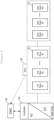
- FIG. 1 is a block diagram of a general energy storage system.
- a battery cell In an energy storage system (ESS), typically a battery cell is a minimum unit of storing energy or power.
- a series/parallel combination of battery cells may form a battery pack, and a plurality of battery packs may form a battery rack.
- a battery rack can be a minimum unit of a battery system as a series/parallel combination of battery packs.
- a battery pack may be referred to as a battery module.
- a battery rack may include a plurality of battery modules and a battery protection unit (BPU) 10 or any other protection device.
- the battery rack can be monitored and controlled through a rack BMS(RBMS).
- the RBMS may monitor a current, a voltage and a temperature, among others, of each battery rack to be managed, calculate a State Of Charge (SOC) of the battery based on monitoring results, and control charging and discharging of the battery rack.
- SOC State Of Charge
- the battery protection unit is a device for protecting the battery rack from an abnormal current and a fault current in the battery rack.
- the BPU may include a main contactor (MC), a fuse, a circuit breaker (CB) or a disconnect switch (DS) .
- the BPU may control a battery system rack by rack through on/off controlling the main contactor (MC) based on a control from the Rack BMS.
- the BPU 10 may also protect the battery rack from a short circuit current using a fuse in the event of a short circuit.
- a general battery system can be controlled through a protection device such as a BPU 10 or a switchgear.
- a battery sysesm controller (BSC) 20 is located in each battery section which includes a plurality of batteries, peripheral circuits, and devices to monitor and control objects such as a voltage, a current, a temperature, and a circuit breaker.
- the battery sysesm controller 20 is an uppermost control device in a battery system including at least one battery bank with a plurality of battery racks.
- the battery sysem controller 20 may also be used as a control device in a battery system having a plurality of bank level structures.
- a power conversion system (PCS) 40 installed in each battery section performs charging/discharging based on a charge/discharge command (e.g., a charge or discharge command) from the energy management system (EMS) 30.
- the power conversion system (PCS) 40 may include a power conversion unit (DC/AC inverter) and a controller.
- the output of each BPU 10 may be connected to a power generating device (e.g., photovoltaic device) and the power conversion system 40 through a DC bus, and the power conversion system 40 may be connected to a power grid.
- the energy management system (EMS) 30 or power management system (PMS) may manage the overall energy storage system (ESS).
- a plurality of battery racks may serve as voltage sources, and the PCS charges and discharges the battery racks using a constant current (CC) control method or a constant power (CP) control method.
- CC constant current
- CP constant power
- the performances of battery racks are almost similar (if expressed in equivalent resistance, showing similar resistance values), and the charge/discharge current of each rack appears in a similar level.
- some racks may experience degradation over time.
- new racks can be added to the existing energy system so as to supplement the system performance, which may be referred to as augmentation.
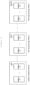
- FIG. 2 is a block diagram of a general energy storage system including new batteries.
- FIG. 2 shows a system in which an energy storage system (e.g., the energy storage system shown in FIG. 1 ) including existing battery racks 10 (old racks) is augmentated with a plurality of new battery racks 10' (new racks).
- an energy storage system e.g., the energy storage system shown in FIG. 1
- existing battery racks 10 old racks
- new battery racks 10' new racks
- the new battery racks 10' are electrically connected to the existing battery racks 10 and can be controlled to charge and discharge, together with the existing battery racks 10 by a control device of the energy storage system.
- a performance difference may appear between the new battery racks 10' and the existing battery racks 10, and a problem arises that the new battery racks 10' follow deteriorated performance of the existing battery racks 10.
- the maximum performance e.g., nominal capacity, period of use, etc.
- the present invention is presented to solve the problems occurring in the existing energy storage system.
- the present invention can minimize the number of batteries installed in the battery system during the entire operation period of the energy storage system, and at the same time improve power efficiency by minimizing the problem of imbalance between new batteries and existing batteries .
- FIG. 3 is a block diagram of a battery system according to embodiments of the present invention.
- a battery system may include a plurality of batteries and may be located within an energy storage system shown in FIG. 1 or FIG. 2 .
- [battery] may mean a battery cell, battery module, battery rack, or battery bank.
- the battery system may include initially installed batteries 100 (first battery) and at least one battery 200 (second battery) that is incorporated into the battery system during operation of the battery system.
- the second battery 200 may be sequentially incorporated into the first batteries 100 N times.
- the second battery 200 may include a first augmenting battery 200-1 to an Nth augmenting battery 200-N that are sequentially incorporated into the system from the first to the Nth times.
- the battery system may be operated based on operation plan information derived by an operation plan establishing apparatus to be described later.
- the operation plan information may include an installation quantity of the first battery, an augmentation time point of the second battery, the quantity of the augmenting second battery at each augmentation point, and discharge energy amount (Wh) and discharge amount (W) of the first and second batteries for each operation section.
- the installation quantity of the first batteries may be determined based on a preset minimum required amount of discharge energy (e.g., required discharge energy amount by a customer).
- the augmentation time point of the second batteries and the quantity of the augmenting second batteries at each augmentation time point may be determined based on the minimum required amount of discharge energy and expected degree of degradation of the battery.
- the discharge energy amount and discharge amount of the first batteries and the second batteries may be defined for each of Nth augmentation operation periods and determined for each of a Nth augmentation operation period so that the first and second batteries have the same discharge time in each of the Nth augmentation operation period.
- the Nth augmentation operation period refers to a period in which the pre-installed battery and the Nth augmentating second battery are operated together.
- the first augmentation operation period is a period in which the first battery 100 and the first augmenting battery 200-1 are operated together
- the second augmentation operation period is a period in which the first battery 100, the first augmenting battery 200-1, and the second augmenting battery 200-2 are operated together
- the Nth augmentation operation period is a period in which the first battery 100 and the first to Nth augmenting batteries (200-1 - 200-N) are operated together.
- the first batteries may be installed and operated according to a number of initial installation batteries included in the operation plan information
- the second batteries (200-1 ⁇ 200-N) may be sequentially augmentated and operated according to the Nth augmentation time point and augmentation quantity included in the operation plan information.
- the first and second batteries may be controlled according to discharge energy amount and discharge amount for each operation period included in the operation plan information.
- the discharge energy amount and discharge amount included in the operation plan information are pre-derived values so that the first batteries and the second batteries have the same discharge time in each operation period, and thus, performance imbalance between the first batteries and the second batteries can be minimized in the augmentation operation period.
- FIG. 4 is an operational flowchart of a method for establishing an operation plan for a battery system according to embodiments of the present invention.
- the operation plan establishing apparatus may determine a number of first batteries to be initially installed in the battery system (S410).
- the operation plan establishing apparatus may determine the number of first batteries based on a preset minimum required amount of discharge energy. For example, if the minimum required amount of discharge energy is set to 1000 [MWh] and each battery rack has a capacity of 335 [KWh], the number of first batteries may be determined to be 3420 to satisfy the minimum required amount of discharge energy during the initial operation period (period of operation with only the first battery).
- the operation plan establishing apparatus may determine the number of first batteries by considering the minimum required amount of discharge energy and expected degradation degree of the first batteries.
- the number of first batteries may be determined as a minimum value of a natural number exceeding [(minimum required amount of discharge energy / discharge energy amount per battery) * ⁇ ], and ⁇ may be defined as a specific value between 1.1 and 1.2.
- the number of first batteries may be determined as a quantity capable of discharging more than the minimum required amount of discharge energy even at the end of the initial operation period (e.g., 5 years).
- the operation plan establishing apparatus may determine the augmentation time point of the second batteries sequentially incorporated into the first batteries and the number of the second batteries to be incorporated for each augmentation time (S420).
- the operation plan establishing apparatus may determine the augmentation time point of the second batteries and the number of augmentation numbers for each augmentation time based on the minimum required amount of discharge energy and the expected degradation degree of the first batteries.
- FIG. 6 is an example of operation plan information according to embodiments of the present invention.
- the operation plan establishing apparatus may calculate expected amount of discharge energy (1145.284, 1144.138, ... , 789.100) of the first batteries (initially installed battery) for each unit period (year) of the preset total operation period (20 years).
- the expected amount of discharge energy may be calculated according to capacity of each first battery (335 KWh), the total number of first batteries (3420), and a predefined expected degradation degree of the first battery.
- the expected degradation degree may be pre-derived experimentally or pre-derived using a degradation model, and stored in a storage device.
- the operation plan establishing apparatus may determine a time point (6th year) when the expected amount of discharge energy of the first batteries becomes less than the minimum required amount of discharge energy (1000 MHh) as the first augmentation time point.
- the operation plan establishing apparatus may determine the quantity of first augmentation batteries to be augmentated at first augmentation time.
- the operation plan establishing apparatus may determine the quantity of the first augmentation batteries based on the minimum required amount of discharge energy and the expected discharge energy amount according to the expected degradation degree of the battery.
- the first augmentation operation period may be predefined as 5 years, and the operation plan establishing apparatus may determine the number of second batteries (270) so that the expected total amount of discharge energy at the end of the first augmentation operation period (10th year) exceeds the minimum required amount of discharge energy (1000 MHh).
- the operation plan establishing apparatus may determine the quantity of Nth augmenting batteries to be merged at N-th augmentation time using the method described above.
- the first augmentation time is determined as year 6 and the number of the first augmentation is determined to be 270
- the second augmentation time is determined to be year 11 and the number of the second augmentation is determined to be 270
- the third augmentation time is determined to be year 16 and the number of the third augmentation is determined to be 235.
- the operation plan establishing apparatus may generate operation plan information including the number of first batteries determined in steps S410 and S420, the augmentation time points of the second batteries (first to Nth augmentation time points), and the augmentation quantity of the second batteries for each augmentation time point (S430).
- the operation plan establishing apparatus may transmit the generated operation plan information to a managing terminal so that the battery system can be initially designed and operated according to the operation plan information.
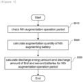
- FIG. 5 is an operational flowchart of a method for deriving operation plan information according to embodiments of the present invention.
- a method for calculating the discharge energy amount (Wh) and discharge amount (W) of the first and second batteries for each Nth augmentation operation section will be described in detail.
- the operation plan establishing apparatus may check the Nth augmentation operation period (S510). Specifically, the operation plan establishing apparatus may confirm the augmentation operation period for each preset order. For example, each of the 1st augmentation operation period to the Nth augmentation operation period may be set to 5 years, as shown in FIG. 6 .
- the operation plan establishing apparatus may determine the Nth augmentation time point based on the Nth augmentation operation period. For example, as shown in FIG. 6 , the augmentation time for each order may be determined as the 6th year (the first augmentation time), the 11th year (the second augmentation time), and the 16th year (the third augmentation time).
- the operation plan establishing apparatus may calculate the augmentation quantity at the Nth augmentation time point (S520).
- the operation plan establishing apparatus may determine the quantity of augmentation batteries based on the minimum required discharge energy amount and the expected discharge energy amount according to the expected degradation degree of the already installed battery.
- the operation plan establishing apparatus may calculate the discharge energy amount and the discharge amount of the first and second batteries for the Nth augmentation operation period (S530).
- the operation plan establishing apparatus may generate discharge energy amount and discharge amount of the first and second batteries so that the first and second batteries have the same discharge time based on the expected discharge energy amount of the pre-installed batteries and the preset total discharge amount.
- the operation plan establishing apparatus may calculate the discharge energy amount and discharge amount of the first and second batteries for the Nth augmentation operation period based on Equation 1 below.
- E _ n ⁇ 1 / T _ backup + E _ n / T _ backup P _ total
- E_(n-1) refers to the expected discharge energy amount of the pre-installed batteries at the end of the Nth augmentation operation period
- E_(n) refers to the expected discharge energy amount of the Nth augmentation battery at the end of the Nth augmentation operation period
- T_backup refers to the discharge time
- P_total means the total amount of discharge.
- the operation plan establishing apparatus may derive the discharge energy amount (E_(n )) and discharge time (T_backup), based on Equation 1 above, which satisfies a condition that the total discharge energy amount in the Nth augmentation operation period exceeds the minimum required amount of discharge energy.
- the operation plan establishing apparatus may calculate the discharge energy amount and the discharge amount of the first and second batteries for the Nth augmentation operation period using the derived values.
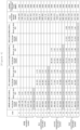
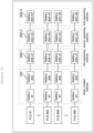
- FIG. 7 is an example of operation plan information according to embodiments of the present invention.
- the total discharge amount in all augmentation operation sections may be preset to 300 [MW].
- the number of first augmentated batteries may be determined to be 270, as described with reference to FIGS. 4 and 6 .
- the operation plan establishing apparatus may calculate the discharge energy amount and discharge amount of the first and second batteries for the first augmentation operation period based on Equation 1 above.
- E _ 0 / T _ backup + E _ 1 / T _ backup P _ total
- E_(0) is 925.389 [MWh], which is the expected discharge energy amount of the pre-installed battery (i.e., initially installed battery) at the end of the first augmentation operation period, and P_total is 300 [MW].
- the operation plan establishing apparatus may derive a discharge energy amount (E_(1)) and a discharge time (T_backup) of the first augmentating batteries that satisfy equation 1 above and the condition that the total amount of discharge energy (the sum of the amount of discharge energy of the initially installed battery and the first augmentating battery) in the first augmentation operation period exceeds the minimum required amount of discharge energy 1000 [MWh].
- the operation plan establishing apparatus may terminate the calculation process when values that satisfy equation 1 and conditions are derived, by repeating a process of changing E_(1) and T_backup and substituting them into equation 1 and conditions thereof.
- the discharge energy amount (E_(1)) of the first augmentating batteries is derived as 80.923 [MWh] and the discharge time (T_backup) is derived as 3.35 [hr].
- the operation plan establishing apparatus may use the derived values to calculate (E_(0) / T_backup) the discharge amount of the first battery (275.87537 [MW]) and the discharge amount of the first augmentating batteries (24.12463 [MW]) may be calculated (E_(1) / T_backup).
- the operation plan establishing apparatus may calculate a discharge energy amount and a discharge amount of the first batteries (initial installaed battery) and the second batteries (first to third augmentating batteries) for the second and third augmentation operation periods in the same manner as above (see FIG. 7 ).
- the operation plan establishing apparatus may generate operation plan information including the discharge energy amount and the discharge amount of the first and second batteries for each of the first to Nth augmentation operation periods and transmit it to a control device of the battery system, and thus, the battery system may operate according to the operation plan information. Accordingly, the battery system may be controlled so that the old and new batteries have the same discharge time during all augmentation operation periods, thereby minimizing performance imbalance between batteries and improving power efficiency.
- FIG. 8 is an example of a battery system according to a comparative example of the present invention
- FIG. 9 is an example of a battery system according to embodiments of the present invention.
- the battery system in FIG. 8 is a battery system that does not incorporate new batteries and operates only with initially installed batteries.
- 4,500 battery racks, each with a capacity of 335 [KWh] must be initially installed in order to satisfy the minimum required amount of discharge energy (1000 [MHh]) per unit period during the total operation period (20 years).
- the battery system according to the embodiment of the present invention shown in FIG. 9 may be operated with 3420 battery racks during the initial operation period, making it possible to design the initial system with a 24% lower number of battery racks than the comparative example.
- the battery racks can be sequentially installed and operated with 270 units in the 6th year, 270 units in the 11th year, and 235 units in the 16th year, and thus, 4195 battery racks are installed during the total operation period, which is possible to operate with a 6.7% lower number of battery racks than the comparative example.
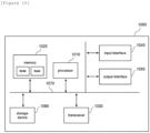
- FIG. 10 is a block diagram of an apparatus for establishing an operation plan according to embodiments of the present invention.
- the apparatus for establishing an operation plan 1000 may include at least one processor 1010, a memory 1020 that stores at least one command executed through the processor, and a transceiver 1030 which is connected to the network to perform communication.
- the at least one instruction may include an instruction to derive a number of first batteries initially installed in the battery system based on a preset minimum required amount of discharge energy; and an instruction to derive operation plan information including augmentation time points for the second batteries to be sequentially incorporated into the first batteries and a number of the second batteries to be incorporated for each augmentation time point, based on the minimum required amount of discharge energy and an expected degradation degree of the first batteries.
- the instruction to derive the operation plan information may include an instruction to determine the number of the second batteries to be incorporated at each augmentation time based on the minimum required amount of discharge energy and a discharge energy amount according to an expected degradation degree of pre-installed batteries.
- the instruction to derive the operation plan information may include an instruction to calculate the discharge energy amount and the discharge amount of the second batteries for Nth augmentation operation period, whrerin the Nth augmentation operation period is defined as a period in which pre-installed batteries and the Nth augmenting second batteries are operated together.
- the instruction to calculate the discharge energy amount and the discharge amount of the second batteries for Nth augmentation operation period may include an instruction to calculate the discharge energy amount and the discharge amount of the second batteries so that the second batteries have the same discharge time (back-up time) as the discharge time of the pre-installed batteries based on a discharge energy amount according to the expected degradation degree of the pre-installed batteries and a preset total discharge amount.
- the instruction to calculate the discharge energy amount and the discharge amount of the second batteries for Nth augmentation operation period may include an instruction to calculate the discharge energy amount and the discharge amount of the second batteries at the end of the Nth augmentation operation period so that the second batteries have the same discharge time (back-up time) as the discharge time of the pre-installed batteries based on an expected discharge energy amount of the pre-installed batteries at the end of the Nth augmentation operation period and a preset total discharge amount and an instruction to determine the calculated discharge energy amount and the discharge amount as the discharge energy amount and the discharge amount of the second batteries for the Nth augmentation operation period.
- the at least one instruction may further include an instruction to transmit the discharge energy amount and discharge amount of the first batteries and the second batteries to the battery system so that the first batteries and the second batteries are operated with the same discharge time during the Nth augmentation operation period.
- the apparatus for establishing an operation plan 1000 may further include an input interface 1040, an output interface 1050, a storage device 1060, etc. Respective components included in the apparatus for establishing an operation plan 1000 are connected by a bus 1070 and can communicate with one another.
- the processor 1010 may mean a central processing unit (CPU), a graphics processing unit (GPU), or a dedicated processor on which methods according to embodiments of the present invention are performed.
- the memory (or storage device) may include at least one of a volatile storage medium and a nonvolatile storage medium.
- the memory may include at least one of read only memory (ROM) and random access memory (RAM).
- the operations of the method according to the embodiments of the present invention may be implemented as a computer-readable program or code on a computer-readable recording medium.
- the computer-readable recording medium includes all types of recording devices in which data readable by a computer system is stored.
- the computer-readable recording medium may be distributed in a network-connected computer system to store and execute computer-readable programs or codes in a distributed manner.
- a block or apparatus corresponds to a method step or feature of a method step.
- aspects described in the context of a method may also represent a feature of a corresponding block or item or a corresponding apparatus.
- Some or all of the method steps may be performed by (or using) a hardware device, such as, for example, a microprocessor, a programmable computer, or an electronic circuit. In some embodiments, one or more of the most important method steps may be performed by such an apparatus.
Landscapes
- Engineering & Computer Science (AREA)
- Power Engineering (AREA)
- Physics & Mathematics (AREA)
- General Physics & Mathematics (AREA)
- Charge And Discharge Circuits For Batteries Or The Like (AREA)
- Supply And Distribution Of Alternating Current (AREA)
- Health & Medical Sciences (AREA)
- General Health & Medical Sciences (AREA)
- Medical Informatics (AREA)
- Secondary Cells (AREA)
Applications Claiming Priority (2)
| Application Number | Priority Date | Filing Date | Title |
|---|---|---|---|
| KR1020220117636A KR20240039281A (ko) | 2022-09-19 | 2022-09-19 | 신규 설치 배터리를 포함하는 배터리 시스템의 운영 계획 수립 장치 및 방법 |
| PCT/KR2023/010006 WO2024063281A1 (ko) | 2022-09-19 | 2023-07-13 | 신규 설치 배터리를 포함하는 배터리 시스템의 운영 계획 수립 장치 및 방법 |
Publications (2)
| Publication Number | Publication Date |
|---|---|
| EP4407832A1 true EP4407832A1 (de) | 2024-07-31 |
| EP4407832A4 EP4407832A4 (de) | 2026-03-25 |
Family
ID=90454496
Family Applications (1)
| Application Number | Title | Priority Date | Filing Date |
|---|---|---|---|
| EP23868341.1A Pending EP4407832A4 (de) | 2022-09-19 | 2023-07-13 | Vorrichtung und verfahren zur erstellung eines betriebsplans für ein batteriesystem mit neu installierten batterien |
Country Status (7)
| Country | Link |
|---|---|
| US (1) | US20250038562A1 (de) |
| EP (1) | EP4407832A4 (de) |
| JP (1) | JP7683129B2 (de) |
| KR (1) | KR20240039281A (de) |
| CN (1) | CN118160187A (de) |
| AU (1) | AU2023344235A1 (de) |
| WO (1) | WO2024063281A1 (de) |
Family Cites Families (11)
| Publication number | Priority date | Publication date | Assignee | Title |
|---|---|---|---|---|
| JP5519692B2 (ja) | 2009-10-30 | 2014-06-11 | 日本碍子株式会社 | 二次電池の制御方法および電力貯蔵装置 |
| JP6157880B2 (ja) | 2013-03-04 | 2017-07-05 | 株式会社東芝 | 複数電池を有する二次電池システム及び充放電電力等の配分方法 |
| CN204424402U (zh) * | 2014-12-25 | 2015-06-24 | 宁德时代新能源科技有限公司 | 磷酸铁锂电池组的被动均衡系统 |
| KR102332337B1 (ko) * | 2015-01-30 | 2021-11-29 | 삼성에스디아이 주식회사 | 배터리 시스템 및 이를 포함하는 에너지 저장 시스템 |
| JP6550896B2 (ja) | 2015-04-27 | 2019-07-31 | 富士電機株式会社 | 運用シミュレーション装置、運用シミュレーションシステム、発電機用の蓄電池設備のシミュレーション方法、及びプログラム |
| KR102030872B1 (ko) * | 2015-11-17 | 2019-10-10 | 주식회사 엘지화학 | 에너지 저장 시스템의 사양 설계 장치 및 방법 |
| KR20170062132A (ko) | 2015-11-27 | 2017-06-07 | 주식회사 엘지화학 | 배터리 관리 시스템 및 배터리 관리 방법 |
| KR20180049543A (ko) * | 2016-11-03 | 2018-05-11 | 주식회사 로코스 | 배터리팩 확장성을 고려한 에너지 저장 시스템 및 그 제어 방법 |
| JP7182142B2 (ja) | 2018-04-23 | 2022-12-02 | パナソニックIpマネジメント株式会社 | データセンタのバックアップ用電源システム、バックアップ用電池ラック |
| WO2019215967A1 (ja) | 2018-05-09 | 2019-11-14 | 日本電気株式会社 | 制御装置、電力管理システム、制御方法及びプログラム |
| KR20220117636A (ko) | 2021-02-17 | 2022-08-24 | 주식회사 보삼바이오산업 | 파래 강정의 제조방법 |
-
2022
- 2022-09-19 KR KR1020220117636A patent/KR20240039281A/ko active Pending
-
2023
- 2023-07-13 EP EP23868341.1A patent/EP4407832A4/de active Pending
- 2023-07-13 WO PCT/KR2023/010006 patent/WO2024063281A1/ko not_active Ceased
- 2023-07-13 US US18/709,107 patent/US20250038562A1/en active Pending
- 2023-07-13 JP JP2024523961A patent/JP7683129B2/ja active Active
- 2023-07-13 AU AU2023344235A patent/AU2023344235A1/en active Pending
- 2023-07-13 CN CN202380014185.9A patent/CN118160187A/zh active Pending
Also Published As
| Publication number | Publication date |
|---|---|
| US20250038562A1 (en) | 2025-01-30 |
| AU2023344235A1 (en) | 2024-05-02 |
| EP4407832A4 (de) | 2026-03-25 |
| KR20240039281A (ko) | 2024-03-26 |
| CN118160187A (zh) | 2024-06-07 |
| WO2024063281A1 (ko) | 2024-03-28 |
| JP2024536599A (ja) | 2024-10-04 |
| JP7683129B2 (ja) | 2025-05-26 |
Similar Documents
| Publication | Publication Date | Title |
|---|---|---|
| EP4293867A1 (de) | Energiespeichersystem und verfahren zur steuerung der erdungsstruktur eines energiespeichersystems | |
| US20260081446A1 (en) | Energy storage system including newly installed battery racks and method for controlling the same | |
| EP4293852A1 (de) | Energiespeichersystem im zusammenhang mit einem solarsystem und verfahren zur steuerung eines energiespeichersystems | |
| KR20230022475A (ko) | 전력 분배 방법 및 이를 이용하는 에너지 저장 시스템 | |
| EP4407832A1 (de) | Vorrichtung und verfahren zur erstellung eines betriebsplans für ein batteriesystem mit neu installierten batterien | |
| EP4415209B1 (de) | Batteriesteuerungsvorrichtung zur reaktion auf den verlust einer kommunikationssituation und energiespeichersystem damit | |
| EP4391274B1 (de) | Energiespeichersystem zum optimalen betrieb eines neu installierten batteriegestells und steuerungsverfahren dafür | |
| AU2022342981A1 (en) | Energy storage system comprising new installation battery rack, and method for controlling same | |
| EP4439281A1 (de) | Vorrichtungsverwaltungssystem und programmverwaltungsverfahren dafür | |
| EP4489254A1 (de) | Batterieverwaltungsvorrichtung eines batteriesystems mit zusätzlicher batterie und steuerungsverfahren dafür | |
| EP4414730A1 (de) | Batteriesteuerungsvorrichtung zur reaktion auf eine abnormale kommunikationssituation und energiespeichersystem damit | |
| JP2025026520A5 (de) | ||
| CN121336340A (zh) | 电池控制装置和方法 | |
| EP4693809A1 (de) | Batteriesystem und betriebsverfahren dafür | |
| EP4708620A1 (de) | Vorrichtung und verfahren zur steuerung einer batterie | |
| CN118159857A (zh) | 用于通信丢失的电池控制装置以及包括该电池控制装置的储能系统 |
Legal Events
| Date | Code | Title | Description |
|---|---|---|---|
| STAA | Information on the status of an ep patent application or granted ep patent |
Free format text: STATUS: THE INTERNATIONAL PUBLICATION HAS BEEN MADE |
|
| PUAI | Public reference made under article 153(3) epc to a published international application that has entered the european phase |
Free format text: ORIGINAL CODE: 0009012 |
|
| STAA | Information on the status of an ep patent application or granted ep patent |
Free format text: STATUS: REQUEST FOR EXAMINATION WAS MADE |
|
| 17P | Request for examination filed |
Effective date: 20240423 |
|
| AK | Designated contracting states |
Kind code of ref document: A1 Designated state(s): AL AT BE BG CH CY CZ DE DK EE ES FI FR GB GR HR HU IE IS IT LI LT LU LV MC ME MK MT NL NO PL PT RO RS SE SI SK SM TR |
|
| DAV | Request for validation of the european patent (deleted) | ||
| DAX | Request for extension of the european patent (deleted) | ||
| A4 | Supplementary search report drawn up and despatched |
Effective date: 20260220 |
|
| RIC1 | Information provided on ipc code assigned before grant |
Ipc: H02J 7/00 20060101AFI20260216BHEP Ipc: H02J 3/28 20060101ALI20260216BHEP Ipc: G01R 31/392 20190101ALI20260216BHEP Ipc: G01R 31/367 20190101ALI20260216BHEP Ipc: H02J 7/84 20260101ALI20260216BHEP Ipc: H02J 7/50 20260101ALI20260216BHEP |