EP4407804A1 - Hochfrequenzstrahlungseinheit und mehrfrequenz-basisstationsantenne - Google Patents
Hochfrequenzstrahlungseinheit und mehrfrequenz-basisstationsantenne Download PDFInfo
- Publication number
- EP4407804A1 EP4407804A1 EP22871347.5A EP22871347A EP4407804A1 EP 4407804 A1 EP4407804 A1 EP 4407804A1 EP 22871347 A EP22871347 A EP 22871347A EP 4407804 A1 EP4407804 A1 EP 4407804A1
- Authority
- EP
- European Patent Office
- Prior art keywords
- vertical section
- balun
- frequency
- radiating unit
- center line
- Prior art date
- Legal status (The legal status is an assumption and is not a legal conclusion. Google has not performed a legal analysis and makes no representation as to the accuracy of the status listed.)
- Pending
Links
Images





Classifications
-
- H—ELECTRICITY
- H01—ELECTRIC ELEMENTS
- H01Q—ANTENNAS, i.e. RADIO AERIALS
- H01Q1/00—Details of, or arrangements associated with, antennas
- H01Q1/36—Structural form of radiating elements, e.g. cone, spiral, umbrella; Particular materials used therewith
-
- H—ELECTRICITY
- H01—ELECTRIC ELEMENTS
- H01Q—ANTENNAS, i.e. RADIO AERIALS
- H01Q1/00—Details of, or arrangements associated with, antennas
- H01Q1/12—Supports; Mounting means
- H01Q1/22—Supports; Mounting means by structural association with other equipment or articles
- H01Q1/24—Supports; Mounting means by structural association with other equipment or articles with receiving set
- H01Q1/241—Supports; Mounting means by structural association with other equipment or articles with receiving set used in mobile communications, e.g. GSM
- H01Q1/246—Supports; Mounting means by structural association with other equipment or articles with receiving set used in mobile communications, e.g. GSM specially adapted for base stations
-
- H—ELECTRICITY
- H01—ELECTRIC ELEMENTS
- H01Q—ANTENNAS, i.e. RADIO AERIALS
- H01Q1/00—Details of, or arrangements associated with, antennas
- H01Q1/12—Supports; Mounting means
-
- H—ELECTRICITY
- H01—ELECTRIC ELEMENTS
- H01Q—ANTENNAS, i.e. RADIO AERIALS
- H01Q1/00—Details of, or arrangements associated with, antennas
- H01Q1/50—Structural association of antennas with earthing switches, lead-in devices or lightning protectors
-
- H—ELECTRICITY
- H01—ELECTRIC ELEMENTS
- H01Q—ANTENNAS, i.e. RADIO AERIALS
- H01Q1/00—Details of, or arrangements associated with, antennas
- H01Q1/52—Means for reducing coupling between antennas; Means for reducing coupling between an antenna and another structure
- H01Q1/521—Means for reducing coupling between antennas; Means for reducing coupling between an antenna and another structure reducing the coupling between adjacent antennas
-
- H—ELECTRICITY
- H01—ELECTRIC ELEMENTS
- H01Q—ANTENNAS, i.e. RADIO AERIALS
- H01Q15/00—Devices for reflection, refraction, diffraction or polarisation of waves radiated from an antenna, e.g. quasi-optical devices
- H01Q15/0006—Devices acting selectively as reflecting surface, as diffracting or as refracting device, e.g. frequency filtering or angular spatial filtering devices
- H01Q15/0053—Selective devices used as spatial filter or angular sidelobe filter
-
- H—ELECTRICITY
- H01—ELECTRIC ELEMENTS
- H01Q—ANTENNAS, i.e. RADIO AERIALS
- H01Q19/00—Combinations of primary active antenna elements and units with secondary devices, e.g. with quasi-optical devices, for giving the antenna a desired directional characteristic
- H01Q19/10—Combinations of primary active antenna elements and units with secondary devices, e.g. with quasi-optical devices, for giving the antenna a desired directional characteristic using reflecting surfaces
-
- H—ELECTRICITY
- H01—ELECTRIC ELEMENTS
- H01Q—ANTENNAS, i.e. RADIO AERIALS
- H01Q19/00—Combinations of primary active antenna elements and units with secondary devices, e.g. with quasi-optical devices, for giving the antenna a desired directional characteristic
- H01Q19/10—Combinations of primary active antenna elements and units with secondary devices, e.g. with quasi-optical devices, for giving the antenna a desired directional characteristic using reflecting surfaces
- H01Q19/104—Combinations of primary active antenna elements and units with secondary devices, e.g. with quasi-optical devices, for giving the antenna a desired directional characteristic using reflecting surfaces using a substantially flat reflector for deflecting the radiated beam, e.g. periscopic antennas
-
- H—ELECTRICITY
- H01—ELECTRIC ELEMENTS
- H01Q—ANTENNAS, i.e. RADIO AERIALS
- H01Q19/00—Combinations of primary active antenna elements and units with secondary devices, e.g. with quasi-optical devices, for giving the antenna a desired directional characteristic
- H01Q19/10—Combinations of primary active antenna elements and units with secondary devices, e.g. with quasi-optical devices, for giving the antenna a desired directional characteristic using reflecting surfaces
- H01Q19/108—Combination of a dipole with a plane reflecting surface
-
- H—ELECTRICITY
- H01—ELECTRIC ELEMENTS
- H01Q—ANTENNAS, i.e. RADIO AERIALS
- H01Q21/00—Antenna arrays or systems
- H01Q21/0006—Particular feeding systems
-
- H—ELECTRICITY
- H01—ELECTRIC ELEMENTS
- H01Q—ANTENNAS, i.e. RADIO AERIALS
- H01Q21/00—Antenna arrays or systems
- H01Q21/06—Arrays of individually energised antenna units similarly polarised and spaced apart
- H01Q21/061—Two dimensional planar arrays
- H01Q21/062—Two dimensional planar arrays using dipole aerials
-
- H—ELECTRICITY
- H01—ELECTRIC ELEMENTS
- H01Q—ANTENNAS, i.e. RADIO AERIALS
- H01Q21/00—Antenna arrays or systems
- H01Q21/24—Combinations of antenna units polarised in different directions for transmitting or receiving circularly and elliptically polarised waves or waves linearly polarised in any direction
- H01Q21/26—Turnstile or like antennas comprising arrangements of three or more elongated elements disposed radially and symmetrically in a horizontal plane about a common centre
-
- H—ELECTRICITY
- H01—ELECTRIC ELEMENTS
- H01Q—ANTENNAS, i.e. RADIO AERIALS
- H01Q21/00—Antenna arrays or systems
- H01Q21/30—Combinations of separate antenna units operating in different wavebands and connected to a common feeder system
-
- H—ELECTRICITY
- H01—ELECTRIC ELEMENTS
- H01Q—ANTENNAS, i.e. RADIO AERIALS
- H01Q5/00—Arrangements for simultaneous operation of antennas on two or more different wavebands, e.g. dual-band or multi-band arrangements
- H01Q5/30—Arrangements for providing operation on different wavebands
- H01Q5/378—Combination of fed elements with parasitic elements
-
- H—ELECTRICITY
- H01—ELECTRIC ELEMENTS
- H01Q—ANTENNAS, i.e. RADIO AERIALS
- H01Q5/00—Arrangements for simultaneous operation of antennas on two or more different wavebands, e.g. dual-band or multi-band arrangements
- H01Q5/40—Imbricated or interleaved structures; Combined or electromagnetically coupled arrangements, e.g. comprising two or more non-connected fed radiating elements
- H01Q5/42—Imbricated or interleaved structures; Combined or electromagnetically coupled arrangements, e.g. comprising two or more non-connected fed radiating elements using two or more imbricated arrays
-
- H—ELECTRICITY
- H01—ELECTRIC ELEMENTS
- H01Q—ANTENNAS, i.e. RADIO AERIALS
- H01Q9/00—Electrically-short antennas having dimensions not more than twice the operating wavelength and consisting of conductive active radiating elements
- H01Q9/04—Resonant antennas
- H01Q9/16—Resonant antennas with feed intermediate between the extremities of the antenna, e.g. centre-fed dipole
-
- Y—GENERAL TAGGING OF NEW TECHNOLOGICAL DEVELOPMENTS; GENERAL TAGGING OF CROSS-SECTIONAL TECHNOLOGIES SPANNING OVER SEVERAL SECTIONS OF THE IPC; TECHNICAL SUBJECTS COVERED BY FORMER USPC CROSS-REFERENCE ART COLLECTIONS [XRACs] AND DIGESTS
- Y02—TECHNOLOGIES OR APPLICATIONS FOR MITIGATION OR ADAPTATION AGAINST CLIMATE CHANGE
- Y02D—CLIMATE CHANGE MITIGATION TECHNOLOGIES IN INFORMATION AND COMMUNICATION TECHNOLOGIES [ICT], I.E. INFORMATION AND COMMUNICATION TECHNOLOGIES AIMING AT THE REDUCTION OF THEIR OWN ENERGY USE
- Y02D30/00—Reducing energy consumption in communication networks
- Y02D30/70—Reducing energy consumption in communication networks in wireless communication networks
Definitions
- the present disclosure relates to the technical field of antenna communication, and in particular to a high-frequency radiating unit and a multi-frequency base station antenna.
- a low-frequency radiating unit generates a certain excitation signal to its adjacent high-frequency radiating unit, so as to generate parasitic radiation, which causes the deformity of the low-frequency pattern and causes the radiation performance of the low-frequency to be sharply reduced.
- parasitic radiation causes the deformity of the low-frequency pattern and causes the radiation performance of the low-frequency to be sharply reduced.
- the mutual coupling between adjacent arrays is enlarged, and the horizontal beam width is widened, resulting in a decrease in gain.
- a high-frequency radiating unit includes: a radiator including a first dipole and a second dipole that are arranged orthogonally, the first dipole including two first radiating plates, and the second dipole including two second radiating plates; an oscillator base including a connecting portion, two first baluns, and two second baluns, wherein bottom ends of the two first baluns and the two second baluns are connected to the connecting portion, top ends of the two first baluns are connected to the two first radiating plates in one-to-one correspondence, top ends of the two second baluns are connected to the two second radiating plates in one-to-one correspondence, and a straight line passing through a center of the connecting portion and perpendicular to a surface of the radiating plate is defined as a center line; a first feeder and a second feeder that are arranged orthogonally.
- the a first feeder is electrically connected to the first dipole
- the second feeder is electrically connected to the second dipole
- the first feeder includes a first vertical section arranged at the periphery of the oscillator base, a distance between the first vertical section and the center line is greater than a distance between the first balun and the center line
- the second feeder includes a second vertical section arranged at the periphery of the oscillator base, and a distance between the second vertical section and the center line is greater than a distance between the second balun and the center line.
- the first vertical section is arranged on a side of the first balun away from the center line O
- the second vertical section is arranged on a side of the second balun away from the center line O.
- Such configuration is different from the prior art that the first vertical section and the second vertical section are arranged in internal wiring grooves of the first balun and the second balun, so that it is not necessary to provide a closed balun structure as in the prior art, but it can provide as an opened balun structure, which can reduce the structural size of the oscillator base to a certain extent, thus achieving the miniaturization of the oscillator base. Meanwhile, the high-frequency parasitic radiation of the balun can be reduced, and the gain of the high-frequency radiating unit can be effectively improved.
- the first feeder further includes a first transverse section, an end of the first transverse section is connected to the first vertical section, the top end of each of the two first baluns is provided with a first groove corresponding to the first transverse section, the first transverse section is provided in the first groove, an insulating spacer is provided between the first transverse section and an inner wall of the first groove, the second feeder further includes a second transverse section, an end of the second transverse section is connected to the second vertical section, the top end of each of the two second baluns is provided with a second groove corresponding to the second transverse section, the second transverse section is provided in the second groove, and an insulating spacer is provided between the second transverse section and an inner wall of the second groove.
- the first feeder further includes a third vertical section connected to another end of the first transverse section, the third vertical section is provided at the periphery of the oscillator base, a distance between the third vertical section and the center line is greater than the distance between the first balun and the center line, the second feeder further includes a fourth vertical section connected to another end of the second transverse section, the fourth vertical section is provided at the periphery of the oscillator base, and a distance between the fourth vertical section and the center line is greater than the distance between the second balun and the center line.
- the oscillator base further includes a first sleeve and a second sleeve that are connected to the connecting portion, the first sleeve is provided corresponding to the first vertical section, the first vertical section extends through the first sleeve, the first vertical section and the first sleeve are configured to be connected to an inner conductor and an outer conductor of one coaxial line, respectively, the second sleeve is provided corresponding to the second vertical section, the second vertical section extends through the second sleeve, and the second vertical section and the second sleeve are configured to be connected to an inner conductor and an outer conductor of another coaxial line, respectively.
- a portion of the connecting portion facing the first sleeve is provided with a first concave surface, the first sleeve is fixed on the first concave surface, a portion of the connecting portion facing the second sleeve is provided with a second concave surface, and the second sleeve is fixed on the second concave surface.
- the first vertical section is configured to be electrically connected to a transmission line for transmitting signals in one of the polarization directions
- the second vertical section is configured to be electrically connected to a transmission line for transmitting signals in another polarization direction.
- the first radiating plate is a first frame, the first frame is a closed frame, or the first frame is provided with a first notch at a portion away from the first balun;
- the second radiating plate is a second frame, the second frame is a closed frame, or the second frame is provided with a second notch at a portion away from the second balun.
- the high-frequency radiating unit further includes a coupling metal plate provided above the radiator at an interval, a surface of the coupling metal plate is provided with a hollow-out opening, and the hollow-out opening is shaped as "+" or "*".
- the coupling metal plate is a square plate, a length of diagonal line of the hollow-out opening is defined as m, m is 0.25 to 0.4 times of a wavelength of a center operating frequency, a length of any side of the coupling metal plate is defined as n, and n is 0.35 to 0.55 times of the wavelength of the center operating frequency.
- aperture sizes of the first dipole and the second dipole are defined as L, L is 0.2 to 0.35 times of the wavelength of the center operating frequency, a distance from a surface of the radiator to a bottom surface of the connecting portion is defined as H, and H is 0.14 to 0.2 times of the wavelength of the center operating frequency.
- a multi-frequency base station antenna includes at least one high-frequency radiating unit, a reflecting plate, and at least one low-frequency radiating unit, and both the high-frequency radiating unit and the low-frequency radiating unit are provided on the reflecting plate.
- the first vertical section is arranged on a side of the first balun away from the center line O
- the second vertical section is arranged on a side of the second balun away from the center line O.
- the coupling metal plate spaced above the radiator can effectively reduce a height and a aperture size of the radiator while realizing the wideband impedance matching of the high-frequency radiating unit, thereby reducing the low-frequency parasitic radiation of the radiator.
- the coupling between the coupling metal plate and the radiator has a high-pass filtering characteristic, which can effectively suppress a coupling signal of the low-frequency radiating unit, thereby reducing the low-frequency parasitic radiation of the high-frequency radiating unit, and effectively improving the low-frequency antenna gain in the multi-frequency base station antenna.
- High-frequency radiating unit 110. Radiator; 111. First radiating plate; 1111. First notch; 1112. First hollow area; 112. Second radiating plate; 1121. Second notch; 1122. Second hollow area; 120. Oscillator base; 121. Connecting portion; 1211. First concave surface; 1212. Second concave surface; 122. First balun; 1221. First groove; 123. Second balun; 1231. Second groove; 124. First sleeve; 125. Second sleeve; 130. First feeder; 131. First vertical section; 132. First transverse section; 133. Third vertical section; 140. Second feeder; 141. Second vertical section; 142. Second transverse section; 150. Coupling metal plate; 151. Hollow-out opening; 200. Low-frequency radiating unit; O. Center line.
- FIG. 1 is a perspective view of a high-frequency radiating unit 100 according to an embodiment of the present disclosure
- FIG. 2 is a top view of the high-frequency radiating unit 100 shown in FIG. 1
- FIG. 3 is a front view of the high-frequency radiating unit 100 shown in FIG. 1
- FIG. 4 is a side view of the high-frequency radiating unit 100 shown in FIG. 1 .
- a high-frequency radiating unit 100 is provided according to an embodiment of the present disclosure, including a radiation body 110, an oscillator base 120, a first feeder 130, and a second feeder 140.
- the radiation body 110 includes a first dipole (not labeled) and a second dipole (not labeled) that are arranged orthogonally.
- the first dipole includes two first radiating plates 111
- the second dipole includes two second radiating plates 112.
- the oscillator base 120 includes a connecting portion 121, two first baluns 122, and two second baluns 123. Bottom ends of the two first baluns 122 and the two second baluns 123 are connected to the connecting portion 121, top ends of the two first baluns 122 are connected to the two first radiating plates 111 in one-to-one correspondence, and top ends of the two second baluns 123 are connected to the two second radiating plates 112 in one-to-one correspondence.
- a straight line passing through a center of the connecting portion 121 and perpendicular to a surface of the radiating plate is defined as a center line O (not labeled).
- the first feeder 130 is orthogonal to the second feeder 140 and is electrically connected to the first dipole (specifically, the electrical connection mode includes a coupled connection mode and a direct connection mode).
- the second feeder 140 is electrically connected to the second dipole (specifically, the electrical connection mode includes a coupled connection mode and a direct connection mode).
- the first feeder 130 includes a first vertical section 131 provided at a periphery of the oscillator base.
- the first vertical section 131 is spaced from one of the first baluns 122, and a distance between the first vertical section 131 and the center line O is greater than a distance between the first balun 122 and the center line O.
- the second feeder 140 includes a second vertical section 141 provided at the periphery of the oscillator base. Specifically, the second vertical section 141 is spaced apart from one of the second baluns 123, and a distance between the second vertical section 141 and the center line O is greater than a distance between the second balun 123 and the center line O.
- the first vertical section 131 and the center line O is greater than the distance between the first balun 122 and the center line O
- the distance between the second vertical section 141 and the center line O is greater than the distance between the second balun 123 and the center line O
- the first vertical section 131 is arranged on a side of the first balun 122 away from the center line O
- the second vertical section 141 is arranged on a side of the second balun 123 away from the center line O.
- Such configuration is different from the prior art that the first vertical section 131 and the second vertical section 141 are arranged in internal wiring grooves of the first balun 122 and the second balun 123, so that it is not necessary to provide a closed balun structure as in the prior art, but it can provide as an opened balun structure, which can reduce the structural size of the oscillator base 120 to a certain extent, thus achieving the miniaturization of the oscillator base 120. Meanwhile, the high-frequency parasitic radiation of the balun can be reduced, and the gain of the high-frequency radiating unit 100 can be effectively improved.
- connection in this embodiment may be realized by coupling connection, or may be realized by mutual electrical contact, which is not limited herein and can be set according to actual requirements.
- the connecting portion 121 is generally designed as, for example, a circular plate, a square plate, a hexagonal plate, an octagonal plate, etc.
- a center of the circular plate is used as a center of the connecting portion 121
- an intersection point of diagonal lines of the square plate, the hexagonal plate, or the octagonal plate is used as the center of the connecting portion 121.
- the connecting portion 121 may be of an irregular structure, and a geometric center of the connecting portion 121 may be used as the center of the connecting portion 121.
- first vertical section 131 being spaced apart from one of the first baluns 122 refers to the presence of an intermediate object between the first vertical section 131 and the one of the first baluns 122, or the intermediate object is absent, which is not limited herein.
- second vertical section 141 being spaced from one of the second baluns 123 refers to an intermediate object between the second vertical section 141 and the one of the second baluns 123, or the intermediate object is absent, which is not limited herein.
- both the first feeder 130 and the second feeder 140 are, for example, feeding plates or feeding rods.
- the first feeder 130 further includes a first transverse section 132.
- One end of the first transverse section 132 is connected to the first vertical section 131.
- the top end of each of the two first baluns 122 is provided with a first groove 1221 corresponding to the first transverse sections 132, the first transverse section 132 is provided in the first groove 1221, and an insulating spacer (not shown) is provided between the first transverse section 132 and an inner wall of the first groove 1221.
- the second feeder 140 further includes a second transverse section 142, one end of the second transverse section 142 is connected to the second vertical section 141, the top end of each of the two second baluns 123 is provided with a second groove 1231 corresponding to the second transverse section 142, the second transverse section 142 is provided in the second groove 1231, and an insulating spacer (not shown) is provided between the second transverse section 142 and an inner wall of the second groove 1231.
- the first transverse section 132 is arranged in the first groove 1221, and is spaced apart from the two first radiating plates 111, so as to be coupled to the two first radiating plates 111 and be responsible for the transmission of signals in one of polarization directions.
- the second transverse section 142 is arranged in the second groove 1231 and is spaced apart from the two second radiating plates 112, so as to be coupled to the two second radiating plates 112 and be responsible for the transmission of signals in the other polarization direction.
- the first transverse section 132 is connected to the inner wall of the first groove 1221 through the insulating spacer, so that the first feeder 130 can be stably arranged on the oscillator base 120.
- the second transverse section 142 is connected to the inner wall of the second groove 1231 through the insulating spacer, so that the second feeder 140 can be stably arranged on the oscillator base 120.
- the insulating spacer is made of an insulating material such as a plastic member, a ceramic member, a rubber member, etc., which can prevent the first transverse section 132 of the first feeder 130 from being electrically connected to the top end of the first balun 122, and also serve to fix the first feeder 130.
- the second transverse section 142 of the second feeder 140 is prevented from being electrically connected to the top end of the second balun 123 while fixing the second feeder 140.
- FIG. 7 is a perspective view of a high-frequency radiating unit 100 according to yet another embodiment
- FIG. 8 is a perspective view of the oscillator base 120 and the feeder according to an embodiment of the present disclosure.
- the first feeder 130 further includes a third vertical section 133 connected to the other end of the first transverse section 132.
- the third vertical section 133 is provided at the periphery of the oscillator base 120.
- the third vertical section 133 is spaced apart from the other first balun 122, and a distance between the third vertical section 133 and the center line O is greater than the distance between the first balun 122 and the center line O.
- the second feeder 140 further includes a fourth vertical section (not shown) connected to the other end of the second transverse section 142.
- the fourth vertical section is provided at the periphery of the oscillator base 120. Specifically, the fourth vertical section is spaced apart from the other second balun 123, and a distance between the fourth vertical section and the center line O is greater than the distance between the second balun 123 and the center line O.
- the third vertical section 133 and the center line O is greater than the distance between the first balun 122 and the center line O
- the distance between the fourth vertical section and the center line O is greater than the distance between the second balun 123 and the center line O
- the third vertical section 133 is arranged on the side of the first balun 122 away from the center line O
- the fourth vertical section is arranged on the side of the second balun 123 away from the center line O.
- Such configuration is different from the prior art that the first vertical section 131 and the second vertical section 141 are arranged in internal wiring grooves of the first balun 122 and the second balun 123, so that it is not necessary to provide a closed balun structure as in the prior art, but it can provide as an opened balun structure, which can reduce the structural size of the oscillator base 120 to a certain extent, thus achieving the miniaturization of the oscillator base 120. Meanwhile, the high-frequency parasitic radiation of the balun can be reduced, and the gain of the high-frequency radiating unit 100 can be effectively improved.
- the oscillator base 120 further includes a first sleeve 124 and a second sleeve 125 that are connected to the connecting portion 121.
- the first sleeve 124 is provided corresponding to the first vertical section 131.
- the first vertical section 131 extends through the first sleeve 124, and the first vertical section 131 and the first sleeve 124 are configured to be connected to an inner conductor and an outer conductor of one coaxial line, respectively.
- the second sleeve 125 is provided corresponding to the second vertical section 141.
- the second vertical section 141 extends through the second sleeve 125, and the second vertical section 141 and the second sleeve 125 are configured to be connected to an inner conductor and an outer conductor of another coaxial line, respectively.
- signals in one of the polarization directions are transmitted, and after the second vertical section 141 and the second sleeve 125 are connected to the other coaxial line, signals in the other polarization direction are transmitted.
- first vertical section 131 is welded to the inner conductor of one of the coaxial lines
- first sleeve 124 is welded to the outer conductor of one of the coaxial lines
- second vertical section 141 is welded to the inner conductor of the other coaxial line
- the second sleeve 125 is welded to the outer conductor of the other coaxial line.
- the first sleeve 124 and the second sleeve 125 can be omitted, and the bottom ends of the first vertical section 131 and the second vertical section 141 may be directly connected (i.e., by welding) to transmission lines such as a microstrip line and a stripline. That is, optionally, the first vertical section 131 is configured to be electrically connected to a transmission line transmitting signals in one of the polarization directions, and the second vertical section 141 is configured to electrically connected to a transmission line for transmitting signals in the other polarization direction.
- a portion of the connecting portion 121 facing the first sleeve 124 is provided with a first concave surface 1211, and the first sleeve 124 is fixed on the first concave surface 1211.
- a portion of the connecting portion 121 facing the second sleeve 125 is provided with a second concave surface 1212, and the second sleeve 125 is fixed on the second concave surface 1212.
- the first concave surface 1211 is an arc-shaped concave surface
- the first sleeve 124 is a sleeve having a circular cross-section.
- An outer wall surface of the first sleeve 124 is adapted to the first concave surface 1211, so as to be stably arranged on the first concave surface 1211.
- the second concave surface 1212 is similarly arranged and is not described herein again.
- radiator 110 and the oscillator base 120 are integrally formed by casting, so that the number of welding spots can be reduced, the production efficiency can be improved, and the product quality can be ensured. Certainly, they can also be connected by welding.
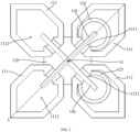
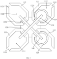
- FIG. 5 is a top view of a high-frequency radiating unit 100 according to another embodiment
- FIG. 6 is a top view of a high-frequency radiating unit 100 according to yet another embodiment.
- the first radiating plate 111 is a first frame
- the first frame is a closed frame (as shown in FIG. 2 ).
- the first frame is provided with a first notch 1111 (as shown in FIG. 5 or FIG. 6 ) at a portion away from the first balun 122.
- the second radiating plate 112 is a second frame, and the second frame is a closed frame (as shown in FIG. 2 ).
- the second frame is provided with a second notch 1121 (as shown in FIG. 5 or FIG. 6 ) at a portion away from the second balun 123.
- the first frame specifically refers to a frame in which a first hollow area 1112 is provided in a middle area of the surface of the first radiating plate 111.
- the second frame specifically refers to a frame in which a second hollow area 1122 provided in a middle area of the surface of the second radiating plate 112.
- the first frame may be either a closed frame or a non-closed frame.
- the first notch 1111 is provided at a portion of the first frame away from the first balun 122.
- the first frame includes two first radiating edges connected to the first balun 122.
- the second frame may be either a closed frame or a non-closed frame.
- a second notch 1121 is provided at a portion of the second frame away from the second balun 123.
- the second frame includes two second radiating edges connected to the second balun 123.
- the specific shape of the first frame and the specific shape of the second frame are not limited herein and may be set according to actual requirements.
- FIG. 9 is a top view of a coupling metal plate 150 according to an embodiment of the present disclosure
- FIG. 10 is a top view of a high-frequency radiating unit 100 according to an embodiment of the present disclosure.
- the high-frequency radiating unit 100 further includes a coupling metal plate 150.
- the coupling metal plate 150 is provided above the radiator 110 at an interval, and a surface of the coupling metal plate 150 is provided with a hollow-out opening 151.
- the hollow-out opening 151 is shaped as "+" or "*".
- the coupling metal plate 150 provided above the radiator 110 can effectively reduce a height and an aperture size of the radiator 110 while realizing the wideband impedance matching of the high-frequency radiating unit 100, thereby reducing the low-frequency parasitic radiation of the radiator 110.
- the coupling between the coupling metal plate 150 and the radiator 110 has a high-pass filtering feature, which can effectively suppress a coupling signal of the low-frequency radiating unit 200, thereby reducing the low-frequency parasitic radiation of the high-frequency radiating unit 100, and effectively improving the low-frequency antenna gain in the multi-frequency base station antenna.
- the high-frequency radiating unit 100 has a higher gain than a conventional high-frequency radiating unit, and has a good performance of suppressing low-frequency parasitic radiation, a distance between the high-frequency radiating unit 100 and the low-frequency radiating unit 200 can be effectively reduced while ensuring antenna performance, the antenna array layout is more compact, and the miniaturization and high performance of the antenna can be achieved.
- the high-frequency radiating unit 100 has a simple structure, is easy to be integrally formed, and has the advantages of miniaturization, low cost, light weight, few welding spots, etc.
- the coupling metal plate 150 is a square plate.
- a length of the diagonal line of the hollow-out opening 151 is defined as m, and m is 0.25 to 0.4 times of a wavelength of a center operating frequency.
- a length of any side of the coupling metal plate 150 is defined as n, and n is 0.35 to 0.55 times of the wavelength of the center operating frequency.
- the operating frequency band is, for example, 1427 MHz to 2690 MHz, and a relative bandwidth is about 61.4%.
- the coupling metal plate 150 is fixed above the radiator 110 through an insulating spacer. Specifically, a distance between the coupling metal plate 150 and an upper surface of the radiator 110 is defined as S, and S is less than 0.05 times of the wavelength of the center operating frequency.
- the aperture sizes of the first dipole and the second dipole are defined as L, and L is 0.2 to 0.35 times of the wavelength of the center operating frequency.
- a distance from a surface of the radiator 110 to a bottom surface of the connecting portion 121 is defined as H, and H is 0.14 to 0.2 times of the wavelength of the center operating frequency.
- the wideband impedance matching of the high-frequency radiating unit 100 can be realized, the working bandwidth with the voltage standing wave ratio less than 1.4 can reach 62%, and the coupling signal with the low frequency can be effectively suppressed.
- the coupling metal plate 150 may be omitted.
- L is, for example, 0.5 times of the wavelength of the center operating frequency
- H is, for example, 0.25 times of the wavelength of the center operating frequency.
- FIG. 11 is a simulation S-parameter curve diagram of the high-frequency radiating unit 100 according to an embodiment of the present disclosure
- FIG. 12 is a comparison diagram of simulation directivity coefficients of a high-frequency radiating unit 100 provided by an embodiment of the present disclosure and a high-frequency radiating unit 100 of a conventional balun structure when an operating frequency is 2.6 GHz.
- S11 refers to a reflection coefficient of one of the polarizations
- S22 refers to a reflection coefficient of the other polarization
- S21 refers to an isolation between the two polarizations.
- the high-frequency radiating unit 100 in this embodiment has good ultra-wideband characteristics.
- FIG. 12 the high-frequency radiating unit 100 in this embodiment has a narrower beam width and a higher directivity coefficient compared with the conventional high-frequency radiating unit, and the radiation performance is improved.
- FIG. 13 is a top view of a multi-frequency base station antenna according to an embodiment of the present disclosure.
- a multi-frequency base station antenna includes at least one high-frequency radiating unit 100 according to any one of the above embodiments, and further includes a reflecting plate (not shown) and at least one low-frequency radiating unit 200. Both the high-frequency radiating unit 100 and the low-frequency radiating unit 200 are provided on the reflecting plate.
- the connecting portion 121 is provided on a surface of the reflecting plate, the first sleeve 124 and the second sleeve 125 extend through the reflecting plate and are connected to the coaxial line. The first sleeve 124 and the second sleeve 125 are also fixed on the reflecting plate.
- the first vertical section 131 and the center line O is greater than the distance between the first balun 122 and the center line O
- the distance between the second vertical section 141 and the center line O is greater than the distance between the second balun 123 and the center line O
- the first vertical section 131 is arranged on a side of the first balun 122 away from the center line O
- the second vertical section 141 is arranged on a side of the second balun 123 away from the center line O.
- Such configuration is different from the prior art that the first vertical section 131 and the second vertical section 141 are arranged in internal wiring grooves of the first balun 122 and the second balun 123, so that it is not necessary to provide a closed balun structure as in the prior art, but it can provide as an opened balun structure, which can reduce the structural size of the oscillator base 120 to a certain extent, thus achieving the miniaturization of the oscillator base 120. Meanwhile, the high-frequency parasitic radiation of the balun can be reduced, and the gain of the high-frequency radiating unit 100 can be effectively improved.
- the coupling metal plate 150 provided above the radiator 110 can effectively reduce a height and the aperture size of the radiator 110 while realizing the wideband impedance matching of the high-frequency radiating unit 100, thereby reducing the low-frequency parasitic radiation of the radiator 110.
- the coupling between the coupling metal plate 150 and the radiator 110 has a high-pass filtering feature, which can effectively suppress a coupling signal of the low-frequency radiating unit 200, thereby reducing the low-frequency parasitic radiation of the high-frequency radiating unit 100, and effectively improving the low-frequency antenna gain in the multi-frequency base station antenna.
- first balun 122 and the second balun 123 may be interpreted as a part of the connecting portion 121, that is, the first balun 122 and the second balun 123 and other parts of the connecting portion 121 are integrally formed, or can also be separated from the other parts of the connecting portion 121, that is, a first protruding body can be manufactured independently, and then combined with the other parts of the connecting portion 121 as a whole.
- first balun 122 and the second balun 123 are a part of the connecting portion 121 that is integrally formed.
- first and second are only used for descriptive purposes and cannot be understood as indicating or implying relative importance or implicitly indicating the number of indicated technical features.
- the features defined with “first” and “second” may explicitly or implicitly include at least one of the features.
- a plurality of means at least two, such as two, three, etc., unless otherwise expressly and specifically defined.
- the terms “mount”, “connect”, “contact”, “fix” and other terms should be understood in a broad sense, for example, they can be fixed connections, detachable connections, or integrated. They can be mechanical connection or electrical connection. They can be directly connected or indirectly connected through an intermediate medium. They can be the connection within two elements or the interaction relationship between two elements, unless otherwise expressly limited. For those skilled in the art, the specific meaning of the above terms in the present disclosure can be understood according to the specific situation.
- the first feature "above” or “below” the second feature may be in direct contact with the first and second features, or the first and second features may be in indirect contact through an intermediate medium.
- the first feature is “above” the second feature, but the first feature is directly above or diagonally above the second feature, or it only means that the horizontal height of the first feature is higher than the second feature.
- the first feature is "below” of the second feature, which can mean that the first feature is directly below or obliquely below the second feature, or simply that the horizontal height of the first feature is less than that of the second feature.
Landscapes
- Engineering & Computer Science (AREA)
- Computer Networks & Wireless Communication (AREA)
- Physics & Mathematics (AREA)
- Electromagnetism (AREA)
- Variable-Direction Aerials And Aerial Arrays (AREA)
Applications Claiming Priority (2)
| Application Number | Priority Date | Filing Date | Title |
|---|---|---|---|
| CN202111124060.0A CN113871856B (zh) | 2021-09-24 | 2021-09-24 | 高频辐射单元与多频基站天线 |
| PCT/CN2022/081832 WO2023045282A1 (zh) | 2021-09-24 | 2022-03-18 | 高频辐射单元与多频基站天线 |
Publications (2)
| Publication Number | Publication Date |
|---|---|
| EP4407804A1 true EP4407804A1 (de) | 2024-07-31 |
| EP4407804A4 EP4407804A4 (de) | 2025-01-22 |
Family
ID=78994074
Family Applications (1)
| Application Number | Title | Priority Date | Filing Date |
|---|---|---|---|
| EP22871347.5A Pending EP4407804A4 (de) | 2021-09-24 | 2022-03-18 | Hochfrequenzstrahlungseinheit und mehrfrequenz-basisstationsantenne |
Country Status (4)
| Country | Link |
|---|---|
| US (1) | US12562463B2 (de) |
| EP (1) | EP4407804A4 (de) |
| CN (1) | CN113871856B (de) |
| WO (1) | WO2023045282A1 (de) |
Families Citing this family (5)
| Publication number | Priority date | Publication date | Assignee | Title |
|---|---|---|---|---|
| WO2021153179A1 (ja) * | 2020-01-28 | 2021-08-05 | 株式会社ヨコオ | 車載用アンテナ装置 |
| CN113871856B (zh) | 2021-09-24 | 2023-08-29 | 京信通信技术(广州)有限公司 | 高频辐射单元与多频基站天线 |
| US20260031549A1 (en) * | 2022-08-05 | 2026-01-29 | Outdoor Wireless Networks LLC | Low-cost ultra-wideband cross-dipole radiating elements and base station antennas including arrays of such radiating elements |
| CN115663459A (zh) * | 2022-10-24 | 2023-01-31 | 中信科移动通信技术股份有限公司 | 双频共口径辐射单元及天线 |
| CN116315591A (zh) * | 2023-02-07 | 2023-06-23 | 中信科移动通信技术股份有限公司 | 天线及基站系统 |
Family Cites Families (23)
| Publication number | Priority date | Publication date | Assignee | Title |
|---|---|---|---|---|
| CN102110875B (zh) * | 2010-12-21 | 2013-12-18 | 东莞市晖速天线技术有限公司 | 移动通信基站天线及其宽频双极化振子 |
| WO2014132254A1 (en) * | 2013-02-26 | 2014-09-04 | Galtronics Corporation Ltd. | Dual-polarized dipole antenna and cruciform coupling element therefore |
| CN203232955U (zh) * | 2013-04-25 | 2013-10-09 | 华为技术有限公司 | 天线振子及具有该天线振子的天线 |
| US9437929B2 (en) * | 2014-01-15 | 2016-09-06 | Raytheon Company | Dual polarized array antenna with modular multi-balun board and associated methods |
| CN205846220U (zh) * | 2016-07-27 | 2016-12-28 | 京信通信技术(广州)有限公司 | 天线辐射单元及多频宽带基站天线 |
| CN206893796U (zh) * | 2017-05-26 | 2018-01-16 | 华南理工大学 | 高异频隔离宽带双频基站天线阵列 |
| US10530068B2 (en) * | 2017-07-18 | 2020-01-07 | The Board Of Regents Of The University Of Oklahoma | Dual-linear-polarized, highly-isolated, crossed-dipole antenna and antenna array |
| EP3692602B1 (de) * | 2017-10-04 | 2023-09-13 | John Mezzalingua Associates LLC | Strahler mit integriertem filter für eine mehrbandantenne |
| WO2019084232A1 (en) * | 2017-10-26 | 2019-05-02 | John Mezzalingua Associates, Llc D/B/A Jma Wireless | HIGH-PERFORMANCE LOW COST MULTI-CELLULAR MULTI-CELLULAR ANTENNA WITH MONOLITHIC METALLIC DIPOLE |
| CN108336486B (zh) * | 2017-12-29 | 2019-09-20 | 京信通信系统(中国)有限公司 | 可调试辐射单元及天线 |
| CN207624897U (zh) * | 2017-12-29 | 2018-07-17 | 京信通信系统(中国)有限公司 | 天线及其高频辐射单元 |
| CN208315769U (zh) * | 2018-06-26 | 2019-01-01 | 江苏亨鑫科技有限公司 | 一种用于多频基站天线中的宽频双极化辐射单元 |
| CN109037919B (zh) * | 2018-08-02 | 2024-02-02 | 摩比天线技术(深圳)有限公司 | 振子组件、振子单元及天线 |
| CN109326872A (zh) | 2018-09-14 | 2019-02-12 | 京信通信系统(中国)有限公司 | 基站天线及其辐射单元 |
| CN110931951B (zh) * | 2018-09-19 | 2023-01-31 | 普罗斯通信技术(苏州)有限公司 | 一种压铸辐射装置及基站阵列天线 |
| CN110011034B (zh) * | 2019-03-29 | 2024-07-26 | 广州杰赛科技股份有限公司 | 一种天线辐射装置 |
| CN112582781A (zh) * | 2019-09-27 | 2021-03-30 | 康普技术有限责任公司 | 辐射元件以及基站天线 |
| CN211980862U (zh) * | 2020-05-07 | 2020-11-20 | 摩比天线技术(深圳)有限公司 | 辐射单元及基站天线 |
| WO2021230922A1 (en) * | 2020-05-15 | 2021-11-18 | John Mezzalingua Associates, Llc D/B/A Jma Wireless | Antenna radiator with pre-configured cloaking to enable dense placement of radiators of multiple bands |
| CA3192130A1 (en) * | 2020-09-08 | 2022-03-17 | Niranjan Sundararajan | High performance folded dipole for multiband antennas |
| CN112216972A (zh) * | 2020-10-16 | 2021-01-12 | 摩比天线技术(深圳)有限公司 | 低频辐射单元及基站天线 |
| CN112490642A (zh) * | 2020-11-25 | 2021-03-12 | 江苏三晟信息科技有限公司 | 一种双极化宽频圆形辐射单元 |
| CN113871856B (zh) * | 2021-09-24 | 2023-08-29 | 京信通信技术(广州)有限公司 | 高频辐射单元与多频基站天线 |
-
2021
- 2021-09-24 CN CN202111124060.0A patent/CN113871856B/zh active Active
-
2022
- 2022-03-18 US US18/691,978 patent/US12562463B2/en active Active
- 2022-03-18 EP EP22871347.5A patent/EP4407804A4/de active Pending
- 2022-03-18 WO PCT/CN2022/081832 patent/WO2023045282A1/zh not_active Ceased
Also Published As
| Publication number | Publication date |
|---|---|
| CN113871856B (zh) | 2023-08-29 |
| EP4407804A4 (de) | 2025-01-22 |
| CN113871856A (zh) | 2021-12-31 |
| US20240380100A1 (en) | 2024-11-14 |
| US12562463B2 (en) | 2026-02-24 |
| WO2023045282A1 (zh) | 2023-03-30 |
Similar Documents
| Publication | Publication Date | Title |
|---|---|---|
| US12562463B2 (en) | High-frequency radiation unit and multi-frequency base station antenna | |
| CN110858679B (zh) | 具有宽带去耦辐射元件的多频带基站天线和相关辐射元件 | |
| CN108701893B (zh) | 双极化天线 | |
| US8269682B2 (en) | Multi-loop antenna module with wide beamwidth | |
| US8866688B2 (en) | Dual-polarized radiation element and planar oscillator thereof | |
| US8482471B2 (en) | Hybrid multiple-input multiple-output antenna module and system of using the same | |
| EP1376757B1 (de) | Richtantenne/Rundstrahlende Antenne für Zweibandbetrieb | |
| CN102918705B (zh) | 多频带天线的双极化辐射元件 | |
| US6734828B2 (en) | Dual band planar high-frequency antenna | |
| EP2073309B1 (de) | Doppelt polarisiertes Strahlungselement für zellulare Basisstationsantennen | |
| EP4383456A1 (de) | Strahlungseinheit mit gemeinsamer apertur und antenne | |
| CN106207495B (zh) | 双极化天线及其辐射单元 | |
| WO2020181774A1 (zh) | 一种宽带双极化天线 | |
| KR102018083B1 (ko) | 광대역 패치 어레이 안테나 장치 | |
| EP4184716B1 (de) | Zweifrequenzantenne und gruppenantenne | |
| EP4521554A1 (de) | Doppelfrequenz-strahlungseinheit mit gemeinsamer apertur und antenne | |
| CN106299643A (zh) | 一种用于移动通信的小型低剖面宽带双极化定向天线 | |
| CN103972658A (zh) | 宽带宽角扫描的双圆极化微带天线 | |
| US20210273339A1 (en) | Wideband Dual-Polarized Four-Quad Loop Antenna | |
| CN110034372A (zh) | 一种平面弯折十字交叉型宽带双极化蝶形振子 | |
| CN116073113A (zh) | 一种多频天线及通信设备 | |
| CN216903365U (zh) | 一种双极化超宽频八木天线 | |
| CN203859224U (zh) | 宽带宽角扫描的双圆极化微带天线 | |
| KR20030093146A (ko) | 광대역 옴니 안테나 | |
| CN114069253A (zh) | 一种双极化超宽频八木天线 |
Legal Events
| Date | Code | Title | Description |
|---|---|---|---|
| STAA | Information on the status of an ep patent application or granted ep patent |
Free format text: STATUS: THE INTERNATIONAL PUBLICATION HAS BEEN MADE |
|
| PUAI | Public reference made under article 153(3) epc to a published international application that has entered the european phase |
Free format text: ORIGINAL CODE: 0009012 |
|
| STAA | Information on the status of an ep patent application or granted ep patent |
Free format text: STATUS: REQUEST FOR EXAMINATION WAS MADE |
|
| 17P | Request for examination filed |
Effective date: 20240318 |
|
| AK | Designated contracting states |
Kind code of ref document: A1 Designated state(s): AL AT BE BG CH CY CZ DE DK EE ES FI FR GB GR HR HU IE IS IT LI LT LU LV MC MK MT NL NO PL PT RO RS SE SI SK SM TR |
|
| REG | Reference to a national code |
Ref country code: DE Ref legal event code: R079 Free format text: PREVIOUS MAIN CLASS: H01Q0021060000 Ipc: H01Q0021260000 |
|
| DAV | Request for validation of the european patent (deleted) | ||
| DAX | Request for extension of the european patent (deleted) | ||
| A4 | Supplementary search report drawn up and despatched |
Effective date: 20241220 |
|
| RIC1 | Information provided on ipc code assigned before grant |
Ipc: H01Q 5/378 20150101ALI20241216BHEP Ipc: H01Q 5/42 20150101ALI20241216BHEP Ipc: H01Q 1/24 20060101ALI20241216BHEP Ipc: H01Q 19/10 20060101ALI20241216BHEP Ipc: H01Q 21/26 20060101AFI20241216BHEP |