EP4407803A1 - Antenne und basisstationsvorrichtung - Google Patents
Antenne und basisstationsvorrichtung Download PDFInfo
- Publication number
- EP4407803A1 EP4407803A1 EP22889146.1A EP22889146A EP4407803A1 EP 4407803 A1 EP4407803 A1 EP 4407803A1 EP 22889146 A EP22889146 A EP 22889146A EP 4407803 A1 EP4407803 A1 EP 4407803A1
- Authority
- EP
- European Patent Office
- Prior art keywords
- frequency band
- cavity
- reflection plate
- phase shifter
- signal transmission
- Prior art date
- Legal status (The legal status is an assumption and is not a legal conclusion. Google has not performed a legal analysis and makes no representation as to the accuracy of the status listed.)
- Pending
Links
- 230000008054 signal transmission Effects 0.000 claims abstract description 87
- 230000005855 radiation Effects 0.000 claims description 31
- 230000010287 polarization Effects 0.000 claims description 18
- 239000003989 dielectric material Substances 0.000 claims description 4
- 238000004891 communication Methods 0.000 abstract description 10
- 238000005516 engineering process Methods 0.000 abstract description 6
- 238000010586 diagram Methods 0.000 description 17
- 230000000052 comparative effect Effects 0.000 description 11
- 238000004088 simulation Methods 0.000 description 8
- 238000000034 method Methods 0.000 description 4
- 230000005540 biological transmission Effects 0.000 description 3
- 230000000694 effects Effects 0.000 description 3
- 229920000915 polyvinyl chloride Polymers 0.000 description 3
- 239000004800 polyvinyl chloride Substances 0.000 description 3
- 238000007789 sealing Methods 0.000 description 3
- 238000009413 insulation Methods 0.000 description 2
- 238000012986 modification Methods 0.000 description 2
- 230000004048 modification Effects 0.000 description 2
- 238000012545 processing Methods 0.000 description 2
- 238000003491 array Methods 0.000 description 1
- 238000011161 development Methods 0.000 description 1
- 230000014509 gene expression Effects 0.000 description 1
- 239000002184 metal Substances 0.000 description 1
- 239000007769 metal material Substances 0.000 description 1
- 230000035515 penetration Effects 0.000 description 1
- 230000035945 sensitivity Effects 0.000 description 1
Images


Classifications
-
- H—ELECTRICITY
- H01—ELECTRIC ELEMENTS
- H01Q—ANTENNAS, i.e. RADIO AERIALS
- H01Q1/00—Details of, or arrangements associated with, antennas
- H01Q1/36—Structural form of radiating elements, e.g. cone, spiral, umbrella; Particular materials used therewith
-
- H—ELECTRICITY
- H01—ELECTRIC ELEMENTS
- H01Q—ANTENNAS, i.e. RADIO AERIALS
- H01Q21/00—Antenna arrays or systems
- H01Q21/24—Combinations of antenna units polarised in different directions for transmitting or receiving circularly and elliptically polarised waves or waves linearly polarised in any direction
- H01Q21/26—Turnstile or like antennas comprising arrangements of three or more elongated elements disposed radially and symmetrically in a horizontal plane about a common centre
-
- H—ELECTRICITY
- H01—ELECTRIC ELEMENTS
- H01Q—ANTENNAS, i.e. RADIO AERIALS
- H01Q1/00—Details of, or arrangements associated with, antennas
- H01Q1/12—Supports; Mounting means
-
- H—ELECTRICITY
- H01—ELECTRIC ELEMENTS
- H01Q—ANTENNAS, i.e. RADIO AERIALS
- H01Q1/00—Details of, or arrangements associated with, antennas
- H01Q1/12—Supports; Mounting means
- H01Q1/22—Supports; Mounting means by structural association with other equipment or articles
- H01Q1/24—Supports; Mounting means by structural association with other equipment or articles with receiving set
- H01Q1/241—Supports; Mounting means by structural association with other equipment or articles with receiving set used in mobile communications, e.g. GSM
- H01Q1/246—Supports; Mounting means by structural association with other equipment or articles with receiving set used in mobile communications, e.g. GSM specially adapted for base stations
-
- H—ELECTRICITY
- H01—ELECTRIC ELEMENTS
- H01Q—ANTENNAS, i.e. RADIO AERIALS
- H01Q1/00—Details of, or arrangements associated with, antennas
- H01Q1/50—Structural association of antennas with earthing switches, lead-in devices or lightning protectors
-
- H—ELECTRICITY
- H01—ELECTRIC ELEMENTS
- H01Q—ANTENNAS, i.e. RADIO AERIALS
- H01Q1/00—Details of, or arrangements associated with, antennas
- H01Q1/52—Means for reducing coupling between antennas; Means for reducing coupling between an antenna and another structure
- H01Q1/521—Means for reducing coupling between antennas; Means for reducing coupling between an antenna and another structure reducing the coupling between adjacent antennas
-
- H—ELECTRICITY
- H01—ELECTRIC ELEMENTS
- H01Q—ANTENNAS, i.e. RADIO AERIALS
- H01Q15/00—Devices for reflection, refraction, diffraction or polarisation of waves radiated from an antenna, e.g. quasi-optical devices
- H01Q15/14—Reflecting surfaces; Equivalent structures
-
- H—ELECTRICITY
- H01—ELECTRIC ELEMENTS
- H01Q—ANTENNAS, i.e. RADIO AERIALS
- H01Q19/00—Combinations of primary active antenna elements and units with secondary devices, e.g. with quasi-optical devices, for giving the antenna a desired directional characteristic
- H01Q19/10—Combinations of primary active antenna elements and units with secondary devices, e.g. with quasi-optical devices, for giving the antenna a desired directional characteristic using reflecting surfaces
- H01Q19/104—Combinations of primary active antenna elements and units with secondary devices, e.g. with quasi-optical devices, for giving the antenna a desired directional characteristic using reflecting surfaces using a substantially flat reflector for deflecting the radiated beam, e.g. periscopic antennas
-
- H—ELECTRICITY
- H01—ELECTRIC ELEMENTS
- H01Q—ANTENNAS, i.e. RADIO AERIALS
- H01Q19/00—Combinations of primary active antenna elements and units with secondary devices, e.g. with quasi-optical devices, for giving the antenna a desired directional characteristic
- H01Q19/10—Combinations of primary active antenna elements and units with secondary devices, e.g. with quasi-optical devices, for giving the antenna a desired directional characteristic using reflecting surfaces
- H01Q19/108—Combination of a dipole with a plane reflecting surface
-
- H—ELECTRICITY
- H01—ELECTRIC ELEMENTS
- H01Q—ANTENNAS, i.e. RADIO AERIALS
- H01Q21/00—Antenna arrays or systems
- H01Q21/0006—Particular feeding systems
-
- H—ELECTRICITY
- H01—ELECTRIC ELEMENTS
- H01Q—ANTENNAS, i.e. RADIO AERIALS
- H01Q21/00—Antenna arrays or systems
- H01Q21/06—Arrays of individually energised antenna units similarly polarised and spaced apart
- H01Q21/061—Two dimensional planar arrays
-
- H—ELECTRICITY
- H01—ELECTRIC ELEMENTS
- H01Q—ANTENNAS, i.e. RADIO AERIALS
- H01Q5/00—Arrangements for simultaneous operation of antennas on two or more different wavebands, e.g. dual-band or multi-band arrangements
- H01Q5/40—Imbricated or interleaved structures; Combined or electromagnetically coupled arrangements, e.g. comprising two or more non-connected fed radiating elements
- H01Q5/42—Imbricated or interleaved structures; Combined or electromagnetically coupled arrangements, e.g. comprising two or more non-connected fed radiating elements using two or more imbricated arrays
-
- H—ELECTRICITY
- H01—ELECTRIC ELEMENTS
- H01P—WAVEGUIDES; RESONATORS, LINES, OR OTHER DEVICES OF THE WAVEGUIDE TYPE
- H01P1/00—Auxiliary devices
Definitions
- This application relates to the field of communications technologies, and in particular, to an antenna and a base station device.
- An antenna and a base station device can reduce interference between radiating elements on different frequency bands, thereby improving a coverage capability of the antenna and improving communication performance.
- an antenna including: a plurality of first frequency band antenna groups, where each first frequency band antenna group includes a phase shifter and a plurality of first frequency band radiating elements; a plurality of second frequency band radiating elements; and a reflection plate.
- a reflection plate through hole corresponding to each first frequency band radiating element is provided on the reflection plate.
- Each first frequency band radiating element includes: a first radiation structure, where the first radiation structure is located on a first side of the reflection plate; a first balun structure, where one part of the first balun structure is located on the first side of the reflection plate and is connected to the first radiation structure, the first balun structure passes through the reflection plate through hole, the other part of the first balun structure is located on a second side of the reflection plate, and the first balun structure is spaced from the reflection plate; and a first signal transmission structure, where the first signal transmission structure is spaced from the first balun structure, and the first signal transmission structure passes through the reflection plate through hole.
- the phase shifter is located on the second side of the reflection plate, the phase shifter includes a first phase shifter cavity, a choke cavity, and a first feed network signal transmission structure located in the first phase shifter cavity, and the choke cavity and the first phase shifter cavity share a part of a cavity wall.
- the part that is of the first balun structure in each first frequency band radiating element and that is located on the second side of the reflection plate is located in the choke cavity.
- the first signal transmission structure in each first frequency band radiating element is electrically connected to the first feed network signal transmission structure.
- each first frequency band radiating element further includes a second signal transmission structure, the second signal transmission structure is spaced from the first balun structure, and the second signal transmission structure passes through the reflection plate through hole.
- the phase shifter further includes a second phase shifter cavity and a second feed network signal transmission structure located in the second phase shifter cavity, the choke cavity and the second phase shifter cavity share a part of a cavity wall, and the first phase shifter cavity and the second phase shifter cavity are located on two opposite sides of the choke cavity, respectively.
- the second signal transmission structure in each first frequency band radiating element is electrically connected to the second feed network signal transmission structure.
- each first frequency band radiating element further includes a first signal exporting structure located outside the choke cavity and outside the first phase shifter cavity.
- a first signal connection hole corresponding to each first signal exporting structure is provided on a cavity wall that is of the first phase shifter cavity and that is away from the reflection plate.
- a second signal connection hole corresponding to each first signal exporting structure is provided on a cavity wall that is of the choke cavity and that is away from the reflection plate.
- the first signal exporting structure is connected to the first signal transmission structure through the corresponding second signal connection hole, and the first signal exporting structure is connected to the first feed network signal transmission structure through the corresponding first signal connection hole.
- Each first frequency band radiating element further includes a second signal exporting structure located outside the choke cavity and outside the second phase shifter cavity.
- a third signal connection hole corresponding to each second signal exporting structure is provided on a cavity wall that is of the second phase shifter cavity and that is away from the reflection plate.
- a fourth signal connection hole corresponding to each second signal exporting structure is provided on the cavity wall that is of the choke cavity and that is away from the reflection plate. The second signal exporting structure is connected to the second signal transmission structure through the corresponding fourth signal connection hole, and the second signal exporting structure is connected to the second feed network signal transmission structure through the corresponding third signal connection hole.
- a cavity wall of the choke cavity is electrically connected to the reflection plate; and an end that is of the part of the first balun structure in the choke cavity and that is away from the reflection plate is connected to the cavity wall of the choke cavity.
- each first frequency band antenna group the plurality of first frequency band radiating elements are arranged in a first direction, the first phase shifter cavity, the choke cavity, and the second phase shifter cavity are arranged in a second direction, the first direction is perpendicular to the second direction, and the first direction and the second direction are both parallel to a plane on which the reflection plate is located.
- a height of the choke cavity is less than one half of a wavelength corresponding to a center frequency of an operating frequency band of the second frequency band radiating element, and the height of the choke cavity is a dimension of the choke cavity in a direction perpendicular to the plane on which the reflection plate is located.
- a width of the choke cavity is less than one third of the wavelength corresponding to the center frequency of the operating frequency band of the second frequency band radiating element, and the width of the choke cavity is a dimension of the choke cavity in the second direction.
- the first frequency band radiating element is a dual-polarized radiating element
- the first signal transmission structure is configured to perform feeding in a first polarization direction
- the second signal transmission structure is configured to perform feeding in a second polarization direction.
- a dielectric material is coated around the first balun structure.
- an operating frequency band of the first frequency band radiating element is greater than an operating frequency band of the second frequency band radiating element.
- each second frequency band radiating element includes a second radiation structure and a second balun structure, the second radiation structure and the second balun structure are located on the first side of the reflection plate, and the second balun structure is connected to the reflection plate.
- a base station device including the foregoing antenna.
- the phase shifter and the first frequency band radiating element are combined, and a part of a cavity wall of the first phase shifter cavity in the phase shifter is used to form the choke cavity.
- the choke cavity may be used to suppress a signal of the second frequency band radiating element in a signal transmission or feeding process, thereby reducing interference between radiating elements on different frequency bands, improving a coverage capability of the antenna, and improving communication performance.
- the choke cavity is formed by using a combination of the phase shifter and the first frequency band radiating element, thereby improving space utilization.
- a plurality of radiating elements in the radiating elements may be excited by using a 1-to-2 power splitter or another type of power splitter, thereby increasing application scenarios of the antenna.
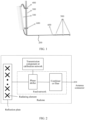
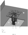
- the base station device includes a base station antenna system.
- the base station antenna system includes an antenna 100, a feeder 200, a pole 300, an antenna adjustment support 400, a grounding apparatus 500, and the like.
- the feeder 200 has a connector sealing piece 600, and the connector sealing piece 600 may be, for example, formed by an insulation sealing tape or a polyvinyl chloride (Polyvinyl Chloride, PVC) insulation tape.
- a radiating element is also referred to as an antenna element, an element, or the like, and is a unit for forming a basic structure of an antenna array.
- the radiating element can effectively radiate or receive a radio wave.
- the antenna includes at least one antenna array including a plurality of radiating elements and a reflection plate. Different radiating elements may correspond to a same frequency or different frequencies.
- the radiating elements are usually placed on the reflection plate, and the reflection plate is usually made of a metal material.
- the reflection plate is also referred to as a base plate, an antenna panel, a metal reflection surface, or the like, and is configured to improve receive sensitivity for antenna signals, and focus antenna signals on a receiving point through reflection.
- the reflection plate not only enhances receiving and transmitting capabilities of the antenna, but also blocks and shields interference of other electric waves from the back (an opposite direction) to received signals.
- the antenna further includes a feed network.
- the antenna arrays receive or transmit radio frequency signals by using respective feed networks. That is, the feed network feeds a signal to the radiating element based on an amplitude and a phase, or sends a received radio signal to a signal processing unit of the base station based on an amplitude and a phase.
- the feed network includes a controlled impedance transmission line, configured to implement impedance matching.
- the feed network includes a phase shifter. The phase shifter is configured to adjust a phase of a received or transmitted signal.
- the feed network may further include a component such as a combiner or a filter that is configured to extend performance.
- the antenna may further include a transmission component, and adjustment between different radiation beam directions may be implemented by using the transmission component.
- the antenna may further include a calibration network, configured to obtain a calibrated signal.
- the foregoing components in the antenna may be disposed in a radome.
- the feed network is connected to the signal processing unit (not shown in the figure) of the base station by using an antenna connector.
- the radome is a structural part that protects the antenna system from being affected by an external environment.
- the radome has a good electromagnetic wave penetration characteristic in terms of electrical performance, and can withstand a harsh external environment in terms of mechanical performance.
- an antenna system includes a plurality of antenna bays.
- One of the antenna bays works on a frequency band of 690 MHz to 960 MHz and includes low-frequency radiating elements.
- Another antenna bay in the plurality of antenna bays works on a frequency band of 1.4 GHz to 2.7 GHz and includes high-frequency radiating elements.
- a signal in the frequency band of 690 MHz to 960 MHz is induced on the another antenna bay. Secondary radiation of the induced signal can interfere with an existing low-frequency signal, and integrity of a directivity pattern of the frequency band of 690 MHz to 960 MHz is affected.
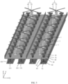
- the antenna structure includes a high-frequency radiating element 01 and a low-frequency radiating element 02.
- a part of a balun structure 04 corresponding to each high-frequency radiating element 01 is wrapped by using a structure 03, to reduce signal interference between radiating elements on different frequency bands.
- this structure brings two problems. One is that extra space is required to dispose the structure 04, thereby increasing a size of the antenna. The other problem is that because the balun structure 04 of each high-frequency radiating element 01 is separately wrapped and isolated, each high-frequency radiating element 01 can only be separately excited.
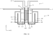
- an embodiment of this application provides an antenna, including: a plurality of first frequency band antenna groups 10, where each first frequency band antenna group 10 includes a phase shifter 20 and a plurality of first frequency band radiating elements 1; a plurality of second frequency band radiating elements 2; and a reflection plate 3.
- a reflection plate through hole 30 corresponding to each first frequency band radiating element 1 is provided on the reflection plate 3.
- Each first frequency band radiating element 1 includes: a first radiation structure 41, where the first radiation structure 41 is located on a first side of the reflection plate 3, and the first side is an upper side of the reflection plate 3 in FIG.
- a first balun structure 51 where one part of the first balun structure 51 is located on the first side of the reflection plate 3 and is connected to the first radiation structure 41, the first balun structure 51 passes through the reflection plate through hole 30, the other part of the first balun structure 51 is located on a second side of the reflection plate 3, the second side is a lower side of the reflection plate 3 in FIG. 10 , and the first balun structure 51 is spaced from the reflection plate 3; and a first signal transmission structure 61, where the first signal transmission structure 61 is spaced from the first balun structure 51, and the first signal transmission structure 61 passes through the reflection plate through hole 30.
- the first signal transmission structure 61 is configured to feed the first frequency band radiating element 1.
- the first signal transmission structure 61 and the first balun structure 51 may be separated by using a dielectric layer, or may be separated by air. If the first signal transmission structure 61 and the first balun structure 51 are separated by air, a support structure needs to be disposed at a position between the first signal transmission structure 61 and the first balun structure 51, to implement a function of supporting and fastening the first signal transmission structure 61.
- the phase shifter 20 is located on the second side of the reflection plate 3, and the phase shifter 20 includes a first phase shifter cavity 101, a choke cavity 111, and a first feed network signal transmission structure 71 located in the first phase shifter cavity 101.
- the choke cavity 111 and the first phase shifter cavity 101 share a part of a cavity wall.
- the first feed network signal transmission structure 71 is configured to transmit a signal in the first phase shifter cavity 101.
- the first phase shifter cavity 101 may change a phase of a signal transmitted by the first feed network signal transmission structure 71 (the first feed network signal transmission structure 71 is not shown in FIG. 5 to FIG. 9 ).
- each first frequency band antenna group 10 the part that is of the first balun structure 51 in each first frequency band radiating element 1 and that is located on the second side of the reflection plate 3 is located in the choke cavity 111, and the choke cavity 111 is configured to suppress a signal of a second frequency band radiating element 2.
- the first signal transmission structure 61 in each first frequency band radiating element 1 is electrically connected to the first feed network signal transmission structure 71
- the first feed network signal transmission structure 71 extends along the cavity in the first phase shifter cavity 101 to transmit a signal
- the first phase shifter cavity 101 extends to a vicinity of each first frequency band radiating element 1 in the first frequency band antenna group 10 and is electrically connected to each first signal transmission structure 61 in the same group.
- FIG. 5 to FIG. 13 are merely diagrams, and structures in different diagrams may be different or cannot be corresponding to each other, but a relationship of main structures is not affected.
- one first frequency band antenna group 10 corresponds to a plurality of first frequency band radiating elements 1 and one phase shifter 20, a part of the first balun structure 51 of each first frequency band radiating element 1 in a same first frequency band antenna group 10 is located in a same choke cavity 111, and the first signal transmission structure 61 of each first frequency band radiating element 1 in a same first frequency band antenna group 10 is electrically connected to a same first feed network signal transmission structure 71 in a same first phase shifter cavity 101.
- radio frequency signals are first transmitted to the first feed network signal transmission structure 71 in the first phase shifter cavity 101, and are transmitted along the first feed network signal transmission structure 71. Then, the signals are transmitted to a plurality of first signal transmission structures 61, the first frequency band radiating elements 1 are fed by using the first signal transmission structures 61, and the first radiation structures 41 are used for radiation.
- the phase shifter 20 and the first frequency band radiating element 1 are combined, and a part of a cavity wall of the first phase shifter cavity 101 in the phase shifter 20 is used to form the choke cavity 111.
- the choke cavity 111 may be used to suppress a signal of the second frequency band radiating element 2 in a signal transmission or feeding process, thereby reducing interference between radiating elements on different frequency bands, improving a coverage capability of the antenna, and improving communication performance.
- the choke cavity 111 is formed by using a combination of the phase shifter 20 and the first frequency band radiating element 1, thereby improving space utilization.
- a plurality of radiating elements in the radiating elements may be excited by using a 1-to-2 power splitter or another type of power splitter, thereby increasing application scenarios of the antenna.
- each first frequency band radiating element 1 further includes a second signal transmission structure 62, the second signal transmission structure 62 is spaced from the first balun structure 51, and the second signal transmission structure 62 passes through the reflection plate through hole 30.
- the phase shifter 20 further includes a second phase shifter cavity 102 and a second feed network signal transmission structure 72 located in the second phase shifter cavity 102.
- the choke cavity 111 and the second phase shifter cavity 102 share a part of a cavity wall.
- the first phase shifter cavity 101 and the second phase shifter cavity 102 are located on two opposite sides of the choke cavity 111, respectively.
- the second signal transmission structure 62 in each first frequency band radiating element 1 is electrically connected to the second feed network signal transmission structure 72.
- the first signal transmission structure 61 and the second signal transmission structure 62 may be configured to implement feeding in different polarization directions, so that the first frequency band radiating element 1 radiates in the two polarization directions, to implement, for example, a dual-polarized antenna.
- Signals corresponding to the two polarization directions are fed through different signal transmission structures, and two phase shifter cavities corresponding to the signals in the two polarization directions need to be disposed.
- the two phase shifter cavities are disposed on the two opposite sides of the choke cavity 111, so that side walls of the two phase shifter cavities are used to form side walls of the choke cavity 111, to improve space utilization, and enable the choke cavity 111 to have a better effect of suppressing a signal of an antenna on another frequency band. For example, as shown in FIG.
- the first phase shifter cavity 101 is located on the left side of the choke cavity 111, and the first phase shifter cavity 101 and the choke cavity 111 share a part of a cavity wall between the two; and the second phase shifter cavity 102 is located on the right side of the choke cavity 111, and the second phase shifter cavity 102 and the choke cavity 111 share a part of a cavity wall between the two.
- each first frequency band radiating element 1 further includes a first signal exporting structure 81 located outside the choke cavity 111 and outside the first phase shifter cavity 101.
- a first signal connection hole 401 corresponding to each first signal exporting structure 81 is provided on a cavity wall that is of the first phase shifter cavity 101 and that is away from the reflection plate 3.
- a second signal connection hole 402 corresponding to each first signal exporting structure 81 is provided on a cavity wall that is of the choke cavity 111 and that is away from the reflection plate 3.
- the first signal exporting structure 81 is connected to the first signal transmission structure 61 through the corresponding second signal connection hole 402, and the first signal exporting structure 81 is connected to the first feed network signal transmission structure 71 through the corresponding first signal connection hole 401, so that the first feed network signal transmission structure 71 is electrically connected to all first signal transmission structures 61 in the same first frequency band antenna group 10.
- Each first frequency band radiating element 1 further includes a second signal exporting structure 82 located outside the choke cavity 111 and outside the second phase shifter cavity 102.
- a third signal connection hole 403 corresponding to each second signal exporting structure 82 is provided on a cavity wall that is of the second phase shifter cavity 102 and that is away from the reflection plate 3.
- a fourth signal connection hole 404 corresponding to each second signal exporting structure 82 is provided on a cavity wall that is of the choke cavity 111 and that is away from the reflection plate 3.
- the second signal exporting structure 82 is connected to the second signal transmission structure 62 through the corresponding fourth signal connection hole 404, and the second signal exporting structure 82 is connected to the second feed network signal transmission structure 72 through the corresponding third signal connection hole 403, so that the second feed network signal transmission structure 72 is electrically connected to all second signal transmission structures 62 in the same first frequency band antenna group 10.
- the cavity wall of the choke cavity 111 is electrically connected to the reflection plate 3, so that when the reflection plate 3 is connected to a fixed potential, for example, when the reflection plate 3 is grounded, the cavity wall of the choke cavity 111 is also grounded.
- An end that is of the part of the first balun structure 51 in the choke cavity 111 and that is away from the reflection plate 3 is connected to the cavity wall of the choke cavity 111. That is, the first balun structure 51 does not directly connect to the reflection plate 3 at a position of the reflection plate 3 to implement grounding, but connects to the cavity wall at the bottom of the choke cavity 111 after passing through the reflection plate through hole 30 to implement grounding.
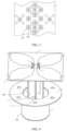
- each first frequency band antenna group 10 a plurality of first frequency band radiating elements 1 are arranged in a first direction Y
- first direction Y For example, in this embodiment of this application, four columns of first frequency band radiating elements 1 and two columns of second frequency band radiating elements 2 are shown.
- the first phase shifter cavity 101, the choke cavity 111, and the second phase shifter cavity 102 are arranged in a second direction X.
- the first direction Y is perpendicular to the second direction X, and the first direction Y and the second direction X are both parallel to a plane on which the reflection plate 3 is located.
- a height h of the choke cavity 111 is less than one half of a wavelength corresponding to a center frequency of an operating frequency band of the second frequency band radiating element 2, and the height h of the choke cavity 111 is a dimension of the choke cavity 111 in a direction perpendicular to the plane on which the reflection plate 3 is located, that is, a dimension of the choke cavity 111 in the first direction Y
- a width w of the choke cavity 111 is less than one third of the wavelength corresponding to the center frequency of the operating frequency band of the second frequency band radiating element 2.
- the width w of the choke cavity 111 is equal to one fourth of the wavelength corresponding to the center frequency of the operating frequency band of the second frequency band radiating element 2.
- the width of the choke cavity 111 is a dimension of the choke cavity 111 in the second direction X. With the foregoing dimensions, a choke effect of the choke cavity 111 can be more significant. It should be noted that, in this embodiment of this application, there is no special limitation on a layout relationship between the first frequency band radiating elements 1 and the second frequency band radiating elements 2, provided that a mechanical size restriction is met and the first frequency band radiating elements 1 and the second frequency band radiating elements 2 can be deployed under a same physical caliber.
- the first frequency band radiating element 1 is a dual-polarized radiating element.
- the first signal transmission structure 61 is configured to perform feeding in a first polarization direction
- the second signal transmission structure 62 is configured to perform feeding in a second polarization direction
- the first polarization direction may be perpendicular to the second polarization direction, to form a vertical dual-polarized radiating element.
- the first frequency band radiating element 1 includes four first radiation structures 41. Two opposite first radiation structures 41 form one group, and there are two groups of radiation structures in total. One group of radiation structures corresponds to a polarization direction, and the other group of radiation structures corresponds to another polarization direction.
- the first signal transmission structure 61 performs feeding from one radiation structure in a same group to the other radiation structure
- the second signal transmission structure 62 performs feeding from one radiation structure in the other group to the other radiation structure.
- a dielectric material 60 is coated around the first balun structure 51, and the choke cavity 111 and the first balun structure 51 form a choke apparatus.
- An operating frequency band of the choke apparatus is used to suppress a signal of a corresponding frequency band.
- the operating frequency band of the formed choke apparatus may be controlled by setting a dielectric constant of the dielectric material 60 based on the dimensions of the choke cavity 111 and an effective length of the first balun structure 51 extending into the choke cavity 111.
- an operating frequency band of the first frequency band radiating element 1 is greater than the operating frequency band of the second frequency band radiating element 2. That is, the first frequency band radiating element 1 is a high-frequency element in the antenna, and the second frequency band radiating element 2 is a low-frequency element in the antenna.
- the operating frequency band of the first frequency band radiating element 1 is 1.4 GHz to 2.7 GHz
- the operating frequency band of the second frequency band radiating element 2 is 0.69 GHz to 0.96 GHz.
- each second frequency band radiating element 2 includes a second radiation structure 42 and a second balun structure 52, the second radiation structure 42 and the second balun structure 52 are located on the first side of the reflection plate 3, and the second balun structure 52 is connected to the reflection plate 3.
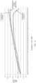
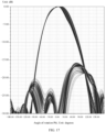
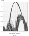
- FIG. 15 is a simulation diagram of gain curves of antennas in a polarization direction on a frequency band of 0.69 GHz to 0.96 GHz according to this embodiment of this application and comparative examples
- FIG. 16 is a simulation diagram of gain curves of antennas in another polarization direction on a frequency band of 0.69 GHz to 0.96 GHz according to this embodiment of this application and comparative examples.
- a comparative example 1 indicates a simulation diagram of a gain curve of an antenna on which only a low-frequency radiating element whose operating frequency band is 0.69 GHz to 0.96 GHz is disposed and works and no radiating element on another frequency band is disposed.
- a comparative example 2 indicates a simulation diagram of a gain curve of an antenna on which a low-frequency radiating element whose operating frequency band is 0.69 GHz to 0.96 GHz and a high-frequency radiating element whose operating frequency band is 1.4 GHz to 2.7 GHz are directly connected together, that is, the low-frequency radiating element and the high-frequency radiating element are directly connected to a reflection plate.
- FIG. 17 shows a directivity pattern of the antenna in the comparative example 1
- FIG. 18 shows a directivity pattern of the antenna in the comparative example 2
- FIG. 19 shows a directivity pattern of the antenna in this embodiment of this application. It can be learned that a directivity pattern indicator of the antenna in this embodiment of this application is basically equivalent to that of the antenna with no high-frequency radiating element. In other words, interference between radiating elements on different frequency bands in this embodiment of this application is very small.
- An embodiment of this application further provides a base station device, including the antenna in any one of the foregoing embodiments.
- a specific structure and a principle of the antenna are the same as those in the foregoing embodiment, and are not described herein again.
- For a basic structure of the base station device refer to FIG. 1 and FIG. 2 and related descriptions.
- At least one means one or more, and "a plurality of means two or more.
- the term “and/or” describes an association relationship between associated objects and represents that three relationships may exist.
- a and/or B may represent the following cases: Only A exists, both A and B exist, and only B exists. A and B may be singular or plural.
- the character “/” generally indicates an “or” relationship between the associated objects.
- At least one of the following” and similar expressions refer to any combination of these terms, including any combination of single or plural terms.
- At least one of a, b, and c may represent: a, b, c, a and b, a and c, b and c, or a, b, and c, where a, b, and c may be singular or plural.
Landscapes
- Engineering & Computer Science (AREA)
- Computer Networks & Wireless Communication (AREA)
- Physics & Mathematics (AREA)
- Electromagnetism (AREA)
- Aerials With Secondary Devices (AREA)
- Variable-Direction Aerials And Aerial Arrays (AREA)
Applications Claiming Priority (2)
| Application Number | Priority Date | Filing Date | Title |
|---|---|---|---|
| CN202111294511.5A CN116073112B (zh) | 2021-11-03 | 2021-11-03 | 天线和基站设备 |
| PCT/CN2022/127224 WO2023078121A1 (zh) | 2021-11-03 | 2022-10-25 | 天线和基站设备 |
Publications (2)
| Publication Number | Publication Date |
|---|---|
| EP4407803A1 true EP4407803A1 (de) | 2024-07-31 |
| EP4407803A4 EP4407803A4 (de) | 2025-01-08 |
Family
ID=86170432
Family Applications (1)
| Application Number | Title | Priority Date | Filing Date |
|---|---|---|---|
| EP22889146.1A Pending EP4407803A4 (de) | 2021-11-03 | 2022-10-25 | Antenne und basisstationsvorrichtung |
Country Status (4)
| Country | Link |
|---|---|
| US (1) | US20240275028A1 (de) |
| EP (1) | EP4407803A4 (de) |
| CN (1) | CN116073112B (de) |
| WO (1) | WO2023078121A1 (de) |
Families Citing this family (5)
| Publication number | Priority date | Publication date | Assignee | Title |
|---|---|---|---|---|
| CN113497341B (zh) * | 2020-03-18 | 2026-01-13 | 户外无线网络有限公司 | 天线组件和基站天线 |
| CN119833948A (zh) * | 2024-01-22 | 2025-04-15 | 中兴通讯股份有限公司 | 阵列天线及其装配方法 |
| CN119542724B (zh) * | 2024-11-05 | 2025-11-11 | 中信科移动通信技术股份有限公司 | 天线馈电结构、基站天线装置、基站 |
| CN119231156A (zh) * | 2024-11-05 | 2024-12-31 | 中信科移动通信技术股份有限公司 | 基站天线装置、基站 |
| CN119231155A (zh) * | 2024-11-05 | 2024-12-31 | 中信科移动通信技术股份有限公司 | 基站天线装置、基站 |
Family Cites Families (15)
| Publication number | Priority date | Publication date | Assignee | Title |
|---|---|---|---|---|
| KR101017670B1 (ko) * | 2007-10-05 | 2011-02-25 | 주식회사 에이스테크놀로지 | 초크 부재를 가지는 안테나 |
| CN103441500B (zh) * | 2013-08-27 | 2015-10-14 | 上海西艾爱电子有限公司 | 一种低功耗无源谐波滤波器 |
| KR101609665B1 (ko) * | 2014-11-11 | 2016-04-06 | 주식회사 케이엠더블유 | 이동통신 기지국 안테나 |
| CN104466426A (zh) * | 2014-11-11 | 2015-03-25 | 李梓萌 | 一种用于基站天线的反射板以及基站天线阵列结构 |
| KR102063622B1 (ko) * | 2015-10-30 | 2020-01-08 | 후아웨이 테크놀러지 컴퍼니 리미티드 | 안테나 시스템 |
| WO2018212825A1 (en) * | 2017-05-17 | 2018-11-22 | Commscope Technologies Llc | Base station antennas having reflector assemblies with rf chokes |
| CN111403893B (zh) * | 2017-09-19 | 2021-11-19 | 上海华为技术有限公司 | 一种基站天线的馈电网络,基站天线及基站 |
| CN108767452B (zh) * | 2018-04-24 | 2024-02-27 | 昆山恩电开通信设备有限公司 | 一种高性能双极化辐射单元及隔离度调节方法 |
| CN111384600A (zh) * | 2018-12-29 | 2020-07-07 | 华为技术有限公司 | 一种馈电系统、阵列天线以及基站 |
| CN111048896B (zh) * | 2019-12-25 | 2025-02-07 | 京信通信技术(广州)有限公司 | 通信系统、天线及其馈电结构 |
| US11611154B2 (en) * | 2020-02-28 | 2023-03-21 | Viettel Group | Printed impedance transformer for broadband dual-polarized antenna |
| CN111525248B (zh) * | 2020-05-09 | 2024-10-29 | 京信通信技术(广州)有限公司 | 一种天线 |
| CN111600126A (zh) * | 2020-06-30 | 2020-08-28 | 京信通信技术(广州)有限公司 | 小型化天线 |
| CN113346251B (zh) * | 2021-04-26 | 2024-07-09 | 广东通宇通讯股份有限公司 | 一种基于辐射单元高度和频段的天线设置方法及天线 |
| CN113410641A (zh) * | 2021-05-24 | 2021-09-17 | 华南理工大学 | 一种带扼流特性的背腔5g基站天线 |
-
2021
- 2021-11-03 CN CN202111294511.5A patent/CN116073112B/zh active Active
-
2022
- 2022-10-25 WO PCT/CN2022/127224 patent/WO2023078121A1/zh not_active Ceased
- 2022-10-25 EP EP22889146.1A patent/EP4407803A4/de active Pending
-
2024
- 2024-04-24 US US18/644,115 patent/US20240275028A1/en active Pending
Also Published As
| Publication number | Publication date |
|---|---|
| CN116073112B (zh) | 2025-06-06 |
| EP4407803A4 (de) | 2025-01-08 |
| US20240275028A1 (en) | 2024-08-15 |
| CN116073112A (zh) | 2023-05-05 |
| WO2023078121A1 (zh) | 2023-05-11 |
Similar Documents
| Publication | Publication Date | Title |
|---|---|---|
| EP4407803A1 (de) | Antenne und basisstationsvorrichtung | |
| EP3975337B1 (de) | Antenneneinheit und endgerätevorrichtung | |
| US11387568B2 (en) | Millimeter-wave antenna array element, array antenna, and communications product | |
| KR102614892B1 (ko) | 안테나 유닛 및 단말 장비 | |
| CN110212283B (zh) | 一种天线单元及终端设备 | |
| EP3852194B1 (de) | Antenne für endgerät | |
| US20230335902A1 (en) | Multi-band antenna and communication device | |
| WO2021104191A1 (zh) | 天线单元及电子设备 | |
| WO2022152022A1 (zh) | 天线装置及电子设备 | |
| EP4576433A1 (de) | Basisstationsantenne und basisstation | |
| EP4576429A1 (de) | Antennenstruktur, antenne und basisstation | |
| US20250379363A1 (en) | Antenna element, antenna system, and communication device | |
| WO2023138324A1 (zh) | 一种天线结构、电子设备及无线网络系统 | |
| US20230344103A1 (en) | Base station antenna | |
| US5877729A (en) | Wide-beam high gain base station communications antenna | |
| WO2021233353A1 (zh) | 天线装置和无线电通信设备 | |
| WO2021083218A1 (zh) | 天线单元及电子设备 | |
| US20260045688A1 (en) | Antenna apparatus, antenna system, and communication device | |
| EP4421994A1 (de) | Übertragungsleitungsverbindungsstruktur | |
| EP4513680A1 (de) | Antenne, kommunikationsvorrichtung und kommunikationssystem | |
| EP4513676A1 (de) | Antenne und basisstation | |
| CN120224603A (zh) | 电子设备 | |
| CN116315590A (zh) | 一种天线结构、基站天线及基站 |
Legal Events
| Date | Code | Title | Description |
|---|---|---|---|
| STAA | Information on the status of an ep patent application or granted ep patent |
Free format text: STATUS: THE INTERNATIONAL PUBLICATION HAS BEEN MADE |
|
| PUAI | Public reference made under article 153(3) epc to a published international application that has entered the european phase |
Free format text: ORIGINAL CODE: 0009012 |
|
| STAA | Information on the status of an ep patent application or granted ep patent |
Free format text: STATUS: REQUEST FOR EXAMINATION WAS MADE |
|
| 17P | Request for examination filed |
Effective date: 20240422 |
|
| AK | Designated contracting states |
Kind code of ref document: A1 Designated state(s): AL AT BE BG CH CY CZ DE DK EE ES FI FR GB GR HR HU IE IS IT LI LT LU LV MC ME MK MT NL NO PL PT RO RS SE SI SK SM TR |
|
| A4 | Supplementary search report drawn up and despatched |
Effective date: 20241206 |
|
| RIC1 | Information provided on ipc code assigned before grant |
Ipc: H01Q 21/26 20060101ALI20241202BHEP Ipc: H01Q 19/10 20060101ALI20241202BHEP Ipc: H01Q 5/42 20150101ALI20241202BHEP Ipc: H01Q 1/24 20060101ALI20241202BHEP Ipc: H01Q 1/52 20060101ALI20241202BHEP Ipc: H01Q 21/00 20060101ALI20241202BHEP Ipc: H01Q 15/14 20060101AFI20241202BHEP |
|
| DAV | Request for validation of the european patent (deleted) | ||
| DAX | Request for extension of the european patent (deleted) |