EP4407744B1 - Rechargeable battery pack - Google Patents
Rechargeable battery pack Download PDFInfo
- Publication number
- EP4407744B1 EP4407744B1 EP23215825.3A EP23215825A EP4407744B1 EP 4407744 B1 EP4407744 B1 EP 4407744B1 EP 23215825 A EP23215825 A EP 23215825A EP 4407744 B1 EP4407744 B1 EP 4407744B1
- Authority
- EP
- European Patent Office
- Prior art keywords
- circuit
- rechargeable battery
- battery pack
- pad
- solder
- Prior art date
- Legal status (The legal status is an assumption and is not a legal conclusion. Google has not performed a legal analysis and makes no representation as to the accuracy of the status listed.)
- Active
Links
Images





Classifications
-
- H—ELECTRICITY
- H01—ELECTRIC ELEMENTS
- H01M—PROCESSES OR MEANS, e.g. BATTERIES, FOR THE DIRECT CONVERSION OF CHEMICAL ENERGY INTO ELECTRICAL ENERGY
- H01M50/00—Constructional details or processes of manufacture of the non-active parts of electrochemical cells other than fuel cells, e.g. hybrid cells
- H01M50/50—Current conducting connections for cells or batteries
- H01M50/572—Means for preventing undesired use or discharge
- H01M50/584—Means for preventing undesired use or discharge for preventing incorrect connections inside or outside the batteries
- H01M50/59—Means for preventing undesired use or discharge for preventing incorrect connections inside or outside the batteries characterised by the protection means
-
- H—ELECTRICITY
- H01—ELECTRIC ELEMENTS
- H01M—PROCESSES OR MEANS, e.g. BATTERIES, FOR THE DIRECT CONVERSION OF CHEMICAL ENERGY INTO ELECTRICAL ENERGY
- H01M10/00—Secondary cells; Manufacture thereof
- H01M10/42—Methods or arrangements for servicing or maintenance of secondary cells or secondary half-cells
- H01M10/425—Structural combination with electronic components, e.g. electronic circuits integrated to the outside of the casing
-
- H—ELECTRICITY
- H01—ELECTRIC ELEMENTS
- H01M—PROCESSES OR MEANS, e.g. BATTERIES, FOR THE DIRECT CONVERSION OF CHEMICAL ENERGY INTO ELECTRICAL ENERGY
- H01M10/00—Secondary cells; Manufacture thereof
- H01M10/42—Methods or arrangements for servicing or maintenance of secondary cells or secondary half-cells
- H01M10/425—Structural combination with electronic components, e.g. electronic circuits integrated to the outside of the casing
- H01M10/4257—Smart batteries, e.g. electronic circuits inside the housing of the cells or batteries
-
- H—ELECTRICITY
- H01—ELECTRIC ELEMENTS
- H01M—PROCESSES OR MEANS, e.g. BATTERIES, FOR THE DIRECT CONVERSION OF CHEMICAL ENERGY INTO ELECTRICAL ENERGY
- H01M10/00—Secondary cells; Manufacture thereof
- H01M10/42—Methods or arrangements for servicing or maintenance of secondary cells or secondary half-cells
- H01M10/48—Accumulators combined with arrangements for measuring, testing or indicating the condition of cells, e.g. the level or density of the electrolyte
-
- H—ELECTRICITY
- H01—ELECTRIC ELEMENTS
- H01M—PROCESSES OR MEANS, e.g. BATTERIES, FOR THE DIRECT CONVERSION OF CHEMICAL ENERGY INTO ELECTRICAL ENERGY
- H01M50/00—Constructional details or processes of manufacture of the non-active parts of electrochemical cells other than fuel cells, e.g. hybrid cells
- H01M50/20—Mountings; Secondary casings or frames; Racks, modules or packs; Suspension devices; Shock absorbers; Transport or carrying devices; Holders
- H01M50/204—Racks, modules or packs for multiple batteries or multiple cells
-
- H—ELECTRICITY
- H01—ELECTRIC ELEMENTS
- H01M—PROCESSES OR MEANS, e.g. BATTERIES, FOR THE DIRECT CONVERSION OF CHEMICAL ENERGY INTO ELECTRICAL ENERGY
- H01M50/00—Constructional details or processes of manufacture of the non-active parts of electrochemical cells other than fuel cells, e.g. hybrid cells
- H01M50/20—Mountings; Secondary casings or frames; Racks, modules or packs; Suspension devices; Shock absorbers; Transport or carrying devices; Holders
- H01M50/284—Mountings; Secondary casings or frames; Racks, modules or packs; Suspension devices; Shock absorbers; Transport or carrying devices; Holders with incorporated circuit boards, e.g. printed circuit boards [PCB]
-
- H—ELECTRICITY
- H01—ELECTRIC ELEMENTS
- H01M—PROCESSES OR MEANS, e.g. BATTERIES, FOR THE DIRECT CONVERSION OF CHEMICAL ENERGY INTO ELECTRICAL ENERGY
- H01M50/00—Constructional details or processes of manufacture of the non-active parts of electrochemical cells other than fuel cells, e.g. hybrid cells
- H01M50/50—Current conducting connections for cells or batteries
- H01M50/502—Interconnectors for connecting terminals of adjacent batteries; Interconnectors for connecting cells outside a battery casing
- H01M50/503—Interconnectors for connecting terminals of adjacent batteries; Interconnectors for connecting cells outside a battery casing characterised by the shape of the interconnectors
-
- H—ELECTRICITY
- H01—ELECTRIC ELEMENTS
- H01M—PROCESSES OR MEANS, e.g. BATTERIES, FOR THE DIRECT CONVERSION OF CHEMICAL ENERGY INTO ELECTRICAL ENERGY
- H01M50/00—Constructional details or processes of manufacture of the non-active parts of electrochemical cells other than fuel cells, e.g. hybrid cells
- H01M50/50—Current conducting connections for cells or batteries
- H01M50/502—Interconnectors for connecting terminals of adjacent batteries; Interconnectors for connecting cells outside a battery casing
- H01M50/519—Interconnectors for connecting terminals of adjacent batteries; Interconnectors for connecting cells outside a battery casing comprising printed circuit boards [PCB]
-
- H—ELECTRICITY
- H01—ELECTRIC ELEMENTS
- H01M—PROCESSES OR MEANS, e.g. BATTERIES, FOR THE DIRECT CONVERSION OF CHEMICAL ENERGY INTO ELECTRICAL ENERGY
- H01M50/00—Constructional details or processes of manufacture of the non-active parts of electrochemical cells other than fuel cells, e.g. hybrid cells
- H01M50/50—Current conducting connections for cells or batteries
- H01M50/502—Interconnectors for connecting terminals of adjacent batteries; Interconnectors for connecting cells outside a battery casing
- H01M50/521—Interconnectors for connecting terminals of adjacent batteries; Interconnectors for connecting cells outside a battery casing characterised by the material
-
- H—ELECTRICITY
- H01—ELECTRIC ELEMENTS
- H01M—PROCESSES OR MEANS, e.g. BATTERIES, FOR THE DIRECT CONVERSION OF CHEMICAL ENERGY INTO ELECTRICAL ENERGY
- H01M50/00—Constructional details or processes of manufacture of the non-active parts of electrochemical cells other than fuel cells, e.g. hybrid cells
- H01M50/50—Current conducting connections for cells or batteries
- H01M50/569—Constructional details of current conducting connections for detecting conditions inside cells or batteries, e.g. details of voltage sensing terminals
-
- H—ELECTRICITY
- H01—ELECTRIC ELEMENTS
- H01M—PROCESSES OR MEANS, e.g. BATTERIES, FOR THE DIRECT CONVERSION OF CHEMICAL ENERGY INTO ELECTRICAL ENERGY
- H01M50/00—Constructional details or processes of manufacture of the non-active parts of electrochemical cells other than fuel cells, e.g. hybrid cells
- H01M50/50—Current conducting connections for cells or batteries
- H01M50/572—Means for preventing undesired use or discharge
- H01M50/584—Means for preventing undesired use or discharge for preventing incorrect connections inside or outside the batteries
- H01M50/588—Means for preventing undesired use or discharge for preventing incorrect connections inside or outside the batteries outside the batteries, e.g. incorrect connections of terminals or busbars
-
- H—ELECTRICITY
- H05—ELECTRIC TECHNIQUES NOT OTHERWISE PROVIDED FOR
- H05K—PRINTED CIRCUITS; CASINGS OR CONSTRUCTIONAL DETAILS OF ELECTRIC APPARATUS; MANUFACTURE OF ASSEMBLAGES OF ELECTRICAL COMPONENTS
- H05K1/00—Printed circuits
- H05K1/02—Details
- H05K1/0277—Bendability or stretchability details
- H05K1/028—Bending or folding regions of flexible printed circuits
-
- H—ELECTRICITY
- H05—ELECTRIC TECHNIQUES NOT OTHERWISE PROVIDED FOR
- H05K—PRINTED CIRCUITS; CASINGS OR CONSTRUCTIONAL DETAILS OF ELECTRIC APPARATUS; MANUFACTURE OF ASSEMBLAGES OF ELECTRICAL COMPONENTS
- H05K1/00—Printed circuits
- H05K1/02—Details
- H05K1/11—Printed elements for providing electric connections to or between printed circuits
- H05K1/118—Printed elements for providing electric connections to or between printed circuits specially for flexible printed circuits, e.g. using folded portions
-
- H—ELECTRICITY
- H05—ELECTRIC TECHNIQUES NOT OTHERWISE PROVIDED FOR
- H05K—PRINTED CIRCUITS; CASINGS OR CONSTRUCTIONAL DETAILS OF ELECTRIC APPARATUS; MANUFACTURE OF ASSEMBLAGES OF ELECTRICAL COMPONENTS
- H05K3/00—Apparatus or processes for manufacturing printed circuits
- H05K3/36—Assembling printed circuits with other printed circuits
- H05K3/361—Assembling flexible printed circuits with other printed circuits
- H05K3/363—Assembling flexible printed circuits with other printed circuits by soldering
-
- C—CHEMISTRY; METALLURGY
- C09—DYES; PAINTS; POLISHES; NATURAL RESINS; ADHESIVES; COMPOSITIONS NOT OTHERWISE PROVIDED FOR; APPLICATIONS OF MATERIALS NOT OTHERWISE PROVIDED FOR
- C09J—ADHESIVES; NON-MECHANICAL ASPECTS OF ADHESIVE PROCESSES IN GENERAL; ADHESIVE PROCESSES NOT PROVIDED FOR ELSEWHERE; USE OF MATERIALS AS ADHESIVES
- C09J2203/00—Applications of adhesives in processes or use of adhesives in the form of films or foils
- C09J2203/33—Applications of adhesives in processes or use of adhesives in the form of films or foils for batteries or fuel cells
-
- H—ELECTRICITY
- H01—ELECTRIC ELEMENTS
- H01M—PROCESSES OR MEANS, e.g. BATTERIES, FOR THE DIRECT CONVERSION OF CHEMICAL ENERGY INTO ELECTRICAL ENERGY
- H01M10/00—Secondary cells; Manufacture thereof
- H01M10/42—Methods or arrangements for servicing or maintenance of secondary cells or secondary half-cells
- H01M10/425—Structural combination with electronic components, e.g. electronic circuits integrated to the outside of the casing
- H01M2010/4271—Battery management systems including electronic circuits, e.g. control of current or voltage to keep battery in healthy state, cell balancing
-
- H—ELECTRICITY
- H05—ELECTRIC TECHNIQUES NOT OTHERWISE PROVIDED FOR
- H05K—PRINTED CIRCUITS; CASINGS OR CONSTRUCTIONAL DETAILS OF ELECTRIC APPARATUS; MANUFACTURE OF ASSEMBLAGES OF ELECTRICAL COMPONENTS
- H05K1/00—Printed circuits
- H05K1/18—Printed circuits structurally associated with non-printed electric components
- H05K1/189—Printed circuits structurally associated with non-printed electric components characterised by the use of flexible or folded printed circuits
-
- H—ELECTRICITY
- H05—ELECTRIC TECHNIQUES NOT OTHERWISE PROVIDED FOR
- H05K—PRINTED CIRCUITS; CASINGS OR CONSTRUCTIONAL DETAILS OF ELECTRIC APPARATUS; MANUFACTURE OF ASSEMBLAGES OF ELECTRICAL COMPONENTS
- H05K2201/00—Indexing scheme relating to printed circuits covered by H05K1/00
- H05K2201/09—Shape and layout
- H05K2201/09145—Edge details
- H05K2201/09181—Notches in edge pads
-
- H—ELECTRICITY
- H05—ELECTRIC TECHNIQUES NOT OTHERWISE PROVIDED FOR
- H05K—PRINTED CIRCUITS; CASINGS OR CONSTRUCTIONAL DETAILS OF ELECTRIC APPARATUS; MANUFACTURE OF ASSEMBLAGES OF ELECTRICAL COMPONENTS
- H05K2201/00—Indexing scheme relating to printed circuits covered by H05K1/00
- H05K2201/10—Details of components or other objects attached to or integrated in a printed circuit board
- H05K2201/10007—Types of components
- H05K2201/10037—Printed or non-printed battery
-
- H—ELECTRICITY
- H05—ELECTRIC TECHNIQUES NOT OTHERWISE PROVIDED FOR
- H05K—PRINTED CIRCUITS; CASINGS OR CONSTRUCTIONAL DETAILS OF ELECTRIC APPARATUS; MANUFACTURE OF ASSEMBLAGES OF ELECTRICAL COMPONENTS
- H05K2201/00—Indexing scheme relating to printed circuits covered by H05K1/00
- H05K2201/10—Details of components or other objects attached to or integrated in a printed circuit board
- H05K2201/10613—Details of electrical connections of non-printed components, e.g. special leads
- H05K2201/10954—Other details of electrical connections
- H05K2201/10984—Component carrying a connection agent, e.g. solder, adhesive
-
- Y—GENERAL TAGGING OF NEW TECHNOLOGICAL DEVELOPMENTS; GENERAL TAGGING OF CROSS-SECTIONAL TECHNOLOGIES SPANNING OVER SEVERAL SECTIONS OF THE IPC; TECHNICAL SUBJECTS COVERED BY FORMER USPC CROSS-REFERENCE ART COLLECTIONS [XRACs] AND DIGESTS
- Y02—TECHNOLOGIES OR APPLICATIONS FOR MITIGATION OR ADAPTATION AGAINST CLIMATE CHANGE
- Y02E—REDUCTION OF GREENHOUSE GAS [GHG] EMISSIONS, RELATED TO ENERGY GENERATION, TRANSMISSION OR DISTRIBUTION
- Y02E60/00—Enabling technologies; Technologies with a potential or indirect contribution to GHG emissions mitigation
- Y02E60/10—Energy storage using batteries
Definitions
- the present disclosure relates to a rechargeable battery pack for increasing electrical connection strength of a flexible printed circuit and a cell supervision circuit.
- a rechargeable battery repeats charging and discharging operations, unlike a primary cell.
- a small rechargeable battery is used for portable small electronic devices such as a mobile phone, a laptop computer, or a camcorder.
- a large capacity and high density rechargeable battery is used to store motor driving power or energy of hybrid vehicles and electric vehicles.
- the rechargeable battery may be used as a single cell as in a small electronic device, or to achieve a large capacity for the purpose of driving a motor it may be used as a module in which a plurality of cells are electrically connected and a pack in which modules are electrically connected.
- a flexible printed circuit (FPC) for sensing voltages or temperatures of the cells and transmitting them to a cell supervision circuit is installed in the rechargeable battery pack.
- the flexible printed circuit and a cell supervision circuit (CSC) (or a cell monitor circuit (CMC)) are electrically connected to each other using a connector.
- CSC cell supervision circuit
- CMC cell monitor circuit
- the present disclosure provides a rechargeable battery pack for electrically connecting a flexible printed circuit and a cell supervision circuit by using an electrically conductive solder instead of a connector.
- An embodiment of the present disclosure provides a rechargeable battery pack including: a cell assembly including at least one battery cell; a side frame accommodating the cell assembly; a flexible printed circuit (FPC) electrically connected to the cell assembly and configured to sense one or more properties of the battery cell; and a cell supervision circuit electrically connected to the flexible printed circuit and on one side of the side frame.
- a cell assembly including at least one battery cell
- a side frame accommodating the cell assembly
- a flexible printed circuit (FPC) electrically connected to the cell assembly and configured to sense one or more properties of the battery cell
- FPC flexible printed circuit
- the flexible printed circuit is electrically connected to the cell supervision circuit by an electrically conductive solder.
- the electrically conductive solder may include a solder or a conductive glue for electrically connecting the flexible circuit substrate and the cell supervision circuit.
- the flexible printed circuit may include a number of circuit lines and a number of conductive pad portions at respective ends of the circuit lines electrically connected to the cell supervision circuit.
- At least one conductive pad portion may protrude from the end of a circuit line with a size that is greater than a width of the circuit line and may be electrically connected to the cell supervision circuit by the electrically conductive solder.
- the conductive pad portion may include a first expansion pad protruding from a first side of the circuit line in a width direction, and a second expansion pad protruding from a second side of the circuit line in the width direction.
- the first expansion pad and the second expansion pad may protrude in a round shape from the end of the circuit line in directions that are opposite to each other.
- a round groove may be between the first expansion pad and the second expansion pad.
- a first step side connected to a lateral side of the flexible printed circuit may be at an end of the first expansion pad.
- a second step side connected to a lateral side of the flexible printed circuit may be at an end of the second expansion pad.
- a plated layer may be on surfaces of the first step side and the second step side.
- a first spaced distance between an outer surface of the first expansion pad and an outer surface of the second expansion pad may be approximately 0.73 to approximately 0.74 times a spaced distance between adjacent circuit lines.
- the first spaced distance may be approximately 1.22 to approximately 1.23 times a second spaced distance between a step of the first expansion pad and a step of the second expansion pad.
- the electrically conductive solder may be a cream solder applied to the first step side, the second step side, and the round groove, may be bonded by laser heat, and may be electrically connected to the cell supervision circuit.
- the electrically conductive solder may be a wire solder applied to the first step side, the second step side, and the round groove, may be bonded by laser heat, and may be electrically connected to the cell supervision circuit.
- At least one circuit line may include a sub-pad portion spaced from the conductive pad portion and electrically connected to the cell supervision circuit by the electrically conductive solder.
- the circuit line may include a slot hole in the sub-pad portion into which the electrically conductive solder is inserted.
- a surface of the electrically conductive solder may be conformally coated.
- the flexible printed circuit is electrically connected to the cell supervision circuit not by using an additional terminal but by using the electrically conductive solder such as a solder, thereby preventing disconnection of lines which might otherwise occur due to pressurized damages at the connected portion of the circuit, and thus allowing stable connection.
- FIG. 1 shows a perspective view of a rechargeable battery pack according to a first embodiment of the present disclosure
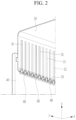
- FIG. 2 shows a schematic perspective view of a flexible circuit substrate and a cell supervision circuit of FIG. 1 electrically connected by an electrically conductive solder.
- the rechargeable battery pack 100 includes a cell assembly 10 including at least one battery cell 11, a side frame 20 for receiving (accommodating) the cell assembly 10, a flexible printed circuit (FPC) 30 electrically connected to the cell assembly 10 and configured to sense one or more properties of the battery cell 11, and a cell supervision circuit 40 connected to the flexible printed circuit 30 and installed on one side of the side frame 20.
- the flexible printed circuit 30 is electrically connected to the cell supervision circuit 40 by an electrically conductive solder 60.
- a plurality of battery cells 11 may be configured with a conventional rechargeable battery for repeatedly performing a charging and discharging operation.
- the side frame 20 may include a first side frame 21 for supporting first lateral sides of a plurality of battery cells 11, a second side frame 22 for supporting second lateral sides of the battery cells 11, a first end frame 23 of which respective ends are connected to first ends of the first side frame 21 and the second side frame 22, and a second end frame 24 of which respective ends are connected to second ends of the first side frame 21 and the second side frame 22.
- the first side frame 21 may be installed to support first sides of the battery cells 11.
- the second side frame 22 may be installed to support seconds sides of the battery cells 11.
- the first end frame 23 may be installed to connect the first ends of the first side frame 21 and the second side frame 22. That is, the first end of the first end frame 23 may be connected to the first end of the first side frame 21 by a fastening member, and the second end of the first end frame 23 may be connected to the first end of the second side frame 22 by the fastening member.
- the second end frame 24 may be installed to connect the second ends of the first side frame 21 and the second side frame 22. That is, the first end of the second end frame 24 may be connected to the second end of the first side frame 21 by the fastening member, and the second end of the second end frame 24 may be connected to the second end of the second side frame 22 by the fastening member.
- the flexible printed circuit (FPC) 30, which is electrically connected to the cell assembly 10 and configured to sense one or more properties of the battery cell 11, may be installed on the side frame 20.
- the flexible printed circuit 30 may be connected to the battery cell 11 and the cell supervision circuit 40, and may sense the voltage or the temperature of the battery cell 11 and may transmit the sensed results to the cell supervision circuit 40.
- the flexible printed circuit 30 may include a plurality of circuit lines 31 coated with an insulation film.
- the circuit lines 31 of the flexible printed circuit 30 may be electrically connected to the cell supervision circuit 40 on a side of the cell assembly 10.
- the cell supervision circuit 40 is installed on one position or location of the cell assembly 10, and in one or more embodiments, it may be installed on the second end frame 24 and it may be electrically connected to the flexible printed circuit 30.
- the present disclosure is not limited to the cell supervision circuit 40 being installed on the position of the second end frame 24, and in one or more embodiments the cell supervision circuit 40 may be installed on a different position such as on the first end frame 23.
- the cell supervision circuit 40 is electrically connected to the flexible printed circuit 30 by the electrically conductive solder 60 without using an additional terminal, thereby preventing disconnection of lines due to pressurized damages at the connected portion, and thus allowing a stable connection.
- the electrically conductive solder 60 may function as a solder for electrically connecting the flexible printed circuit 30 and the cell supervision circuit 40.
- the electrically conductive solder 60 may work as a conductive glue.
- the electrically conductive solder 60 working as a solder will now be described in detail. The electrically conductive solder and the solder will use an identical reference numeral.
- a conductive pad portion 32 for adhering the solder 60 may be formed on the flexible printed circuit 30.
- the conductive pad portion 32 is connected to the flexible printed circuit 30, the solder 60 is adhered to the conductive pad portion 32, and the conductive pad portion 32 may be electrically connected to the circuit lines 31 of the flexible printed circuit 30.
- the rechargeable battery pack 100 may include one conductive pad portion 32 for each of the circuit lines 31.
- the conductive pad portion 32 may have a bigger size (e.g., width) than the width of the circuit lines 31, may protrude from an end of the circuit lines 31, and may be electrically connected to the cell supervision circuit 40 by the solder 60.
- FIG. 3 shows a schematic perspective view of a flexible circuit substrate and a cell supervision circuit of FIG. 2 electrically connected by an electrically conductive solder
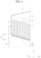
- FIG. 4 shows a schematic perspective view of a state in which an electrically conductive solder of FIG. 2 is omitted
- FIG. 5 shows a state in which a conductive pad portion is formed while an electrically conductive solder of FIG. 4 is omitted.
- the conductive pad portion 32 may include a first expansion pad 321 protruding toward a first side of the circuit line 31 in a width direction, and a second expansion pad 323 protruding toward a second side of the circuit line 31 in the width direction.
- the directions of the first side and the second side are opposite to each other.
- the first expansion pad 321 may be connected to protrude from an end of the circuit line 31 while protruding in a first side direction with respect to a center of the end of the circuit line 31.
- the first expansion pad 321 is made of a same material as the circuit line 31 and protrudes in the first side direction while connected to the circuit line 31, and may protrude in a curved (e.g., round) shape from the end of the circuit line 31.
- the second expansion pad 323 may protrude in an identical or similar shape to the first expansion pad 321 in a second side direction facing the first side direction from the end of the circuit line 31 (e.g., the first expansion pad 321 and the second expansion pad 323 may be symmetric).
- the second expansion pad 323 is made of a same material as the circuit line 31 and protrudes in the second side direction while connected to the circuit line 31, and may protrude in a curved (e.g., round) shape from the end of the circuit line 31.
- the first expansion pad 321 and the second expansion pad 323 respectively protrude in a curved (e.g., round) shape in opposite directions, and may protrude while electrically connected to the end of the circuit line 31 and a round groove 322 may be formed between the first expansion pad 321 and the second expansion pad 323.
- the formation of the round groove 322 between the first expansion pad 321 and the second expansion pad 323 is configured to allow firm electrical connection by providing a sufficient space in which the solder 60 is filled and by increasing a surface area of a portion on which the solder 60 is applied.
- step sides 321a and 323a may be formed at respective ends of the first expansion pad 321 and the second expansion pad 323.
- the formation of the step sides at the first expansion pad 321 and the second expansion pad 323 is to further increase the surface area in which the solder 60 is applied.
- an end of the first expansion pad 321 may be formed to be connected to an edge of the flexible printed circuit 30 along which the first step side 321a is formed.
- An end of the second expansion pad 323 may be formed to be connected to the edge of the flexible printed circuit 30 along which the second step side 323a is formed.
- the solder 60 may be cured once the solder 60 has been sufficiently applied to the space formed by the first step side 321a and the second step side 323a and the space formed by the round groove 322.
- the solder 60 may be applied with the maximum applied area between the flexible printed circuit 30 and the cell supervision circuit 40 and may then be cured so the cell supervision circuit 40 may be connected to the flexible printed circuit 30 while their electrical connection is maximized.
- the solder 60 may be applied as a cream solder to the first step side 321a, the second step side 323a, and the round groove 322, it may be bonded by being cured by laser heat, and may then be electrically connected to the cell supervision circuit 40.
- the solder 60 may be applied to the first step side 321a, the second step side 323a, and the round groove 322 in a wire solder type, and may be cured by laser heat.
- a plated layer may be formed on the surfaces of the first step side 321a and the second step side 323a so if the solder 60 is applied and cured, the electrical connection operation may be performed.
- a first spaced distance between an outer surface of the first expansion pad 321 and an outer surface of the second expansion pad 323 may be within a distance range of approximately 0.73 to approximately 0.74 times the spaced distance of one pair of adjacent circuit lines 31 from among a plurality of circuit lines.
- a distance L1 between the one pair of adjacent circuit lines 31 is approximately 1.5 mm
- a distance L2 between the outer surface of the first expansion pad 321 and the outer surface of the second expansion pad 323 may be approximately 1.1 mm.
- the applied area of the solder 60 at the end of the circuit line is equal to or less than approximately 0.14 mm 2 .
- the applied area of the solder 60 may be maximized compared to an embodiment in which the first expansion pad 321 and the second expansion pad 323 are not formed.
- the surface of the solder 60 connecting the flexible printed circuit 30 and the cell supervision circuit 40 may be conformally coated.
- the conformal coating 70 may be applied to cover the entire outer surface of the solder 60 cured for multiple times to connect the flexible printed circuit 30 and the cell supervision circuit 40.
- the rechargeable battery pack 100 electrically connect the flexible printed circuit 30 and the cell supervision circuit 40 not by using an additional terminal (not shown) but by using the electrically conductive solder 60 such as the solder 60, thereby preventing disconnection of lines which might otherwise occur due to compressed damages at the connection portion and thus allowing a stable connection.
- FIG. 6 shows a schematic perspective view of a flexible circuit substrate electrically connected to a cell supervision circuit according to a second embodiment of the present disclosure by an electrically conductive solder
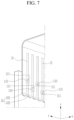
- FIG. 7 shows a schematic perspective view of a state in which an electrically conductive solder of FIG. 6 is omitted
- FIG. 8 shows a schematic lateral view of a state in which an electrically conductive solder of FIG. 6 is omitted.
- the same reference numerals as those in FIG. 1 to FIG. 5 represent identical or similar members with the same or similar functions. No detailed descriptions on the same reference numerals will be provided.
- a sub-pad portion 110 may be formed to be spaced from the conductive pad portion 32 in the respective circuit lines 31 formed on the flexible printed circuit 30 of the rechargeable battery pack according to a second embodiment of the present disclosure (e.g., each circuit line 31 may include a sub-pad portion 110 spaced apart from the conductive pad portion 32).
- the sub-pad portion 110 protrudes from the circuit line 31 from a position spaced from the conductive pad portion 32 by a predetermined distance, and a slot hole 111 may be formed sub-pad portion 110.
- the sub-pad portion 110 protrudes from the circuit line 31 at a position spaced from the conductive pad portion 32, and the sub-pad portion 110 may protrude in a width direction of the circuit line 31.
- a slot hole 111 in a substantial slit shape (e.g., an elongated opening, such as an oval or elliptical shape) that is long in a length direction of the circuit line 31 may be formed at a center position of the sub-pad portion 110.
- the slot hole 111 is shown to have a slit shape in the sub-pad portion 110, and without being limited thereto, it may have a polygonal or round shape.
- solder 60 may be inserted into the slot hole 111 of the sub-pad portion 110 to electrically connect the flexible printed circuit 30 and the cell supervision circuit 40 and thereby increase the strength of the electrical connection.
Landscapes
- Chemical & Material Sciences (AREA)
- Chemical Kinetics & Catalysis (AREA)
- Electrochemistry (AREA)
- General Chemical & Material Sciences (AREA)
- Engineering & Computer Science (AREA)
- Microelectronics & Electronic Packaging (AREA)
- Manufacturing & Machinery (AREA)
- Battery Mounting, Suspending (AREA)
- Connection Of Batteries Or Terminals (AREA)
Applications Claiming Priority (1)
| Application Number | Priority Date | Filing Date | Title |
|---|---|---|---|
| KR1020230000350A KR20240108715A (ko) | 2023-01-02 | 2023-01-02 | 이차전지 팩 |
Publications (2)
| Publication Number | Publication Date |
|---|---|
| EP4407744A1 EP4407744A1 (en) | 2024-07-31 |
| EP4407744B1 true EP4407744B1 (en) | 2025-07-02 |
Family
ID=89190551
Family Applications (1)
| Application Number | Title | Priority Date | Filing Date |
|---|---|---|---|
| EP23215825.3A Active EP4407744B1 (en) | 2023-01-02 | 2023-12-12 | Rechargeable battery pack |
Country Status (6)
| Country | Link |
|---|---|
| US (1) | US20240222727A1 (pl) |
| EP (1) | EP4407744B1 (pl) |
| KR (1) | KR20240108715A (pl) |
| CN (1) | CN118281497A (pl) |
| HU (1) | HUE072561T2 (pl) |
| PL (1) | PL4407744T3 (pl) |
Family Cites Families (9)
| Publication number | Priority date | Publication date | Assignee | Title |
|---|---|---|---|---|
| KR20100106749A (ko) * | 2009-03-24 | 2010-10-04 | 삼성전자주식회사 | 회로기판 접속구조 및 이를 이용한 회로기판 접속방법 |
| WO2010113455A1 (ja) * | 2009-03-31 | 2010-10-07 | 三洋電機株式会社 | 電池モジュール、バッテリシステムおよび電動車両 |
| KR102052062B1 (ko) * | 2012-07-25 | 2019-12-04 | 삼성에스디아이 주식회사 | 땜납부재의 수용을 위한 연결부재를 포함하는 배터리팩 |
| WO2015107583A1 (ja) * | 2014-01-17 | 2015-07-23 | 三洋電機株式会社 | 電源装置 |
| KR102562684B1 (ko) * | 2018-05-15 | 2023-08-03 | 삼성에스디아이 주식회사 | 배터리 팩 |
| KR20220036131A (ko) * | 2020-09-15 | 2022-03-22 | 에스케이온 주식회사 | 센싱 어셈블리 및 배터리 모듈 |
| DE102021103388A1 (de) * | 2020-11-03 | 2022-05-05 | Diehl Ako Stiftung & Co. Kg | Batteriezellenkontaktierungsvorrichtung und Batteriemodul mit einer solchen Batteriezellenkontaktierungsvorrichtung |
| CN114639879A (zh) * | 2020-12-16 | 2022-06-17 | 比亚迪股份有限公司 | 电池信息采样组件、电池模组及电池包 |
| CN217719886U (zh) * | 2022-06-17 | 2022-11-01 | 骆驼集团新能源电池有限公司 | 一种锂离子辅助电池柔性线路板连接结构 |
-
2023
- 2023-01-02 KR KR1020230000350A patent/KR20240108715A/ko active Pending
- 2023-10-16 US US18/487,603 patent/US20240222727A1/en active Pending
- 2023-12-07 CN CN202311682382.6A patent/CN118281497A/zh active Pending
- 2023-12-12 PL PL23215825.3T patent/PL4407744T3/pl unknown
- 2023-12-12 HU HUE23215825A patent/HUE072561T2/hu unknown
- 2023-12-12 EP EP23215825.3A patent/EP4407744B1/en active Active
Also Published As
| Publication number | Publication date |
|---|---|
| KR20240108715A (ko) | 2024-07-09 |
| CN118281497A (zh) | 2024-07-02 |
| PL4407744T3 (pl) | 2025-09-22 |
| HUE072561T2 (hu) | 2025-11-28 |
| US20240222727A1 (en) | 2024-07-04 |
| EP4407744A1 (en) | 2024-07-31 |
Similar Documents
| Publication | Publication Date | Title |
|---|---|---|
| US8603663B2 (en) | Battery pack | |
| US11128021B2 (en) | Battery pack with curved connection portion | |
| US9716258B2 (en) | Battery pack | |
| TWI695533B (zh) | 電池模組及包括彼之電池組 | |
| KR101097257B1 (ko) | 회로 기판 모듈과, 이를 적용한 전지 모듈 | |
| US10818980B2 (en) | Battery pack | |
| US8945757B2 (en) | Battery pack having conductive line holders | |
| CN113906621B (zh) | 电池模块和包括该电池模块的电池组 | |
| US9997809B2 (en) | Battery module | |
| US11394087B2 (en) | Battery module | |
| CN111313119B (zh) | 电池模块以及将单元监控电路载体组装到电池模块的方法 | |
| EP4407744B1 (en) | Rechargeable battery pack | |
| EP4080664A2 (en) | Battery module having flexible busbar | |
| EP4044348A1 (en) | Battery pack | |
| US20230411715A1 (en) | Battery pack | |
| US20240243499A1 (en) | Rechargeable battery pack | |
| KR20130038143A (ko) | 이차전지 | |
| US20240234838A1 (en) | Rechargeable battery pack | |
| US20100316891A1 (en) | Secondary battery including protection circuit module | |
| EP4407745B1 (en) | Circuit board for battery monitoring circuit and wire harness for connection therewith | |
| KR102806986B1 (ko) | 배터리 팩 | |
| US20250233282A1 (en) | Busbar assembly and battery module including the same |
Legal Events
| Date | Code | Title | Description |
|---|---|---|---|
| PUAI | Public reference made under article 153(3) epc to a published international application that has entered the european phase |
Free format text: ORIGINAL CODE: 0009012 |
|
| STAA | Information on the status of an ep patent application or granted ep patent |
Free format text: STATUS: REQUEST FOR EXAMINATION WAS MADE |
|
| 17P | Request for examination filed |
Effective date: 20231212 |
|
| AK | Designated contracting states |
Kind code of ref document: A1 Designated state(s): AL AT BE BG CH CY CZ DE DK EE ES FI FR GB GR HR HU IE IS IT LI LT LU LV MC ME MK MT NL NO PL PT RO RS SE SI SK SM TR |
|
| GRAP | Despatch of communication of intention to grant a patent |
Free format text: ORIGINAL CODE: EPIDOSNIGR1 |
|
| STAA | Information on the status of an ep patent application or granted ep patent |
Free format text: STATUS: GRANT OF PATENT IS INTENDED |
|
| INTG | Intention to grant announced |
Effective date: 20250311 |
|
| RIC1 | Information provided on ipc code assigned before grant |
Ipc: H05K 1/00 20060101ALN20250303BHEP Ipc: H01M 50/569 20210101ALI20250303BHEP Ipc: H01M 50/284 20210101ALI20250303BHEP Ipc: H01M 10/42 20060101AFI20250303BHEP |
|
| GRAS | Grant fee paid |
Free format text: ORIGINAL CODE: EPIDOSNIGR3 |
|
| GRAA | (expected) grant |
Free format text: ORIGINAL CODE: 0009210 |
|
| STAA | Information on the status of an ep patent application or granted ep patent |
Free format text: STATUS: THE PATENT HAS BEEN GRANTED |
|
| AK | Designated contracting states |
Kind code of ref document: B1 Designated state(s): AL AT BE BG CH CY CZ DE DK EE ES FI FR GB GR HR HU IE IS IT LI LT LU LV MC ME MK MT NL NO PL PT RO RS SE SI SK SM TR |
|
| REG | Reference to a national code |
Ref country code: GB Ref legal event code: FG4D |
|
| REG | Reference to a national code |
Ref country code: CH Ref legal event code: EP |
|
| REG | Reference to a national code |
Ref country code: DE Ref legal event code: R096 Ref document number: 602023004530 Country of ref document: DE |
|
| REG | Reference to a national code |
Ref country code: IE Ref legal event code: FG4D |
|
| REG | Reference to a national code |
Ref country code: NL Ref legal event code: MP Effective date: 20250702 |
|
| REG | Reference to a national code |
Ref country code: HU Ref legal event code: AG4A Ref document number: E072561 Country of ref document: HU |
|
| PG25 | Lapsed in a contracting state [announced via postgrant information from national office to epo] |
Ref country code: PT Free format text: LAPSE BECAUSE OF FAILURE TO SUBMIT A TRANSLATION OF THE DESCRIPTION OR TO PAY THE FEE WITHIN THE PRESCRIBED TIME-LIMIT Effective date: 20251103 |
|
| PG25 | Lapsed in a contracting state [announced via postgrant information from national office to epo] |
Ref country code: NL Free format text: LAPSE BECAUSE OF FAILURE TO SUBMIT A TRANSLATION OF THE DESCRIPTION OR TO PAY THE FEE WITHIN THE PRESCRIBED TIME-LIMIT Effective date: 20250702 |
|
| REG | Reference to a national code |
Ref country code: AT Ref legal event code: MK05 Ref document number: 1810323 Country of ref document: AT Kind code of ref document: T Effective date: 20250702 |
|
| PG25 | Lapsed in a contracting state [announced via postgrant information from national office to epo] |
Ref country code: IS Free format text: LAPSE BECAUSE OF FAILURE TO SUBMIT A TRANSLATION OF THE DESCRIPTION OR TO PAY THE FEE WITHIN THE PRESCRIBED TIME-LIMIT Effective date: 20251102 |
|
| PGFP | Annual fee paid to national office [announced via postgrant information from national office to epo] |
Ref country code: DE Payment date: 20251126 Year of fee payment: 3 |
|
| PG25 | Lapsed in a contracting state [announced via postgrant information from national office to epo] |
Ref country code: NO Free format text: LAPSE BECAUSE OF FAILURE TO SUBMIT A TRANSLATION OF THE DESCRIPTION OR TO PAY THE FEE WITHIN THE PRESCRIBED TIME-LIMIT Effective date: 20251002 |
|
| REG | Reference to a national code |
Ref country code: LT Ref legal event code: MG9D |
|
| PG25 | Lapsed in a contracting state [announced via postgrant information from national office to epo] |
Ref country code: AT Free format text: LAPSE BECAUSE OF FAILURE TO SUBMIT A TRANSLATION OF THE DESCRIPTION OR TO PAY THE FEE WITHIN THE PRESCRIBED TIME-LIMIT Effective date: 20250702 |
|
| PG25 | Lapsed in a contracting state [announced via postgrant information from national office to epo] |
Ref country code: FI Free format text: LAPSE BECAUSE OF FAILURE TO SUBMIT A TRANSLATION OF THE DESCRIPTION OR TO PAY THE FEE WITHIN THE PRESCRIBED TIME-LIMIT Effective date: 20250702 |
|
| PG25 | Lapsed in a contracting state [announced via postgrant information from national office to epo] |
Ref country code: HR Free format text: LAPSE BECAUSE OF FAILURE TO SUBMIT A TRANSLATION OF THE DESCRIPTION OR TO PAY THE FEE WITHIN THE PRESCRIBED TIME-LIMIT Effective date: 20250702 |
|
| PGFP | Annual fee paid to national office [announced via postgrant information from national office to epo] |
Ref country code: HU Payment date: 20251212 Year of fee payment: 3 Ref country code: FR Payment date: 20251128 Year of fee payment: 3 |
|
| PG25 | Lapsed in a contracting state [announced via postgrant information from national office to epo] |
Ref country code: GR Free format text: LAPSE BECAUSE OF FAILURE TO SUBMIT A TRANSLATION OF THE DESCRIPTION OR TO PAY THE FEE WITHIN THE PRESCRIBED TIME-LIMIT Effective date: 20251003 |
|
| PG25 | Lapsed in a contracting state [announced via postgrant information from national office to epo] |
Ref country code: CZ Free format text: LAPSE BECAUSE OF FAILURE TO SUBMIT A TRANSLATION OF THE DESCRIPTION OR TO PAY THE FEE WITHIN THE PRESCRIBED TIME-LIMIT Effective date: 20250702 Ref country code: SE Free format text: LAPSE BECAUSE OF FAILURE TO SUBMIT A TRANSLATION OF THE DESCRIPTION OR TO PAY THE FEE WITHIN THE PRESCRIBED TIME-LIMIT Effective date: 20250702 |
|
| PG25 | Lapsed in a contracting state [announced via postgrant information from national office to epo] |
Ref country code: LV Free format text: LAPSE BECAUSE OF FAILURE TO SUBMIT A TRANSLATION OF THE DESCRIPTION OR TO PAY THE FEE WITHIN THE PRESCRIBED TIME-LIMIT Effective date: 20250702 |
|
| PG25 | Lapsed in a contracting state [announced via postgrant information from national office to epo] |
Ref country code: BG Free format text: LAPSE BECAUSE OF FAILURE TO SUBMIT A TRANSLATION OF THE DESCRIPTION OR TO PAY THE FEE WITHIN THE PRESCRIBED TIME-LIMIT Effective date: 20250702 |
|
| PGFP | Annual fee paid to national office [announced via postgrant information from national office to epo] |
Ref country code: PL Payment date: 20251128 Year of fee payment: 3 |
|
| PG25 | Lapsed in a contracting state [announced via postgrant information from national office to epo] |
Ref country code: RS Free format text: LAPSE BECAUSE OF FAILURE TO SUBMIT A TRANSLATION OF THE DESCRIPTION OR TO PAY THE FEE WITHIN THE PRESCRIBED TIME-LIMIT Effective date: 20251002 |
|
| PG25 | Lapsed in a contracting state [announced via postgrant information from national office to epo] |
Ref country code: ES Free format text: LAPSE BECAUSE OF FAILURE TO SUBMIT A TRANSLATION OF THE DESCRIPTION OR TO PAY THE FEE WITHIN THE PRESCRIBED TIME-LIMIT Effective date: 20250702 |
|
| PG25 | Lapsed in a contracting state [announced via postgrant information from national office to epo] |
Ref country code: RO Free format text: LAPSE BECAUSE OF FAILURE TO SUBMIT A TRANSLATION OF THE DESCRIPTION OR TO PAY THE FEE WITHIN THE PRESCRIBED TIME-LIMIT Effective date: 20250702 |
|
| PG25 | Lapsed in a contracting state [announced via postgrant information from national office to epo] |
Ref country code: SM Free format text: LAPSE BECAUSE OF FAILURE TO SUBMIT A TRANSLATION OF THE DESCRIPTION OR TO PAY THE FEE WITHIN THE PRESCRIBED TIME-LIMIT Effective date: 20250702 |
|
| PG25 | Lapsed in a contracting state [announced via postgrant information from national office to epo] |
Ref country code: DK Free format text: LAPSE BECAUSE OF FAILURE TO SUBMIT A TRANSLATION OF THE DESCRIPTION OR TO PAY THE FEE WITHIN THE PRESCRIBED TIME-LIMIT Effective date: 20250702 |
|
| PG25 | Lapsed in a contracting state [announced via postgrant information from national office to epo] |
Ref country code: IT Free format text: LAPSE BECAUSE OF FAILURE TO SUBMIT A TRANSLATION OF THE DESCRIPTION OR TO PAY THE FEE WITHIN THE PRESCRIBED TIME-LIMIT Effective date: 20250702 |
|
| PG25 | Lapsed in a contracting state [announced via postgrant information from national office to epo] |
Ref country code: EE Free format text: LAPSE BECAUSE OF FAILURE TO SUBMIT A TRANSLATION OF THE DESCRIPTION OR TO PAY THE FEE WITHIN THE PRESCRIBED TIME-LIMIT Effective date: 20250702 Ref country code: SK Free format text: LAPSE BECAUSE OF FAILURE TO SUBMIT A TRANSLATION OF THE DESCRIPTION OR TO PAY THE FEE WITHIN THE PRESCRIBED TIME-LIMIT Effective date: 20250702 |