EP4407714A2 - Sekundärbatterie und herstellungsverfahren dafür sowie batteriemodul, batteriepack und vorrichtung mit der sekundärbatterie - Google Patents
Sekundärbatterie und herstellungsverfahren dafür sowie batteriemodul, batteriepack und vorrichtung mit der sekundärbatterie Download PDFInfo
- Publication number
- EP4407714A2 EP4407714A2 EP24182464.8A EP24182464A EP4407714A2 EP 4407714 A2 EP4407714 A2 EP 4407714A2 EP 24182464 A EP24182464 A EP 24182464A EP 4407714 A2 EP4407714 A2 EP 4407714A2
- Authority
- EP
- European Patent Office
- Prior art keywords
- positive electrode
- battery
- secondary battery
- optionally
- transition metal
- Prior art date
- Legal status (The legal status is an assumption and is not a legal conclusion. Google has not performed a legal analysis and makes no representation as to the accuracy of the status listed.)
- Pending
Links
Images


Classifications
-
- H—ELECTRICITY
- H01—ELECTRIC ELEMENTS
- H01M—PROCESSES OR MEANS, e.g. BATTERIES, FOR THE DIRECT CONVERSION OF CHEMICAL ENERGY INTO ELECTRICAL ENERGY
- H01M4/00—Electrodes
- H01M4/02—Electrodes composed of, or comprising, active material
- H01M4/36—Selection of substances as active materials, active masses, active liquids
- H01M4/362—Composites
- H01M4/364—Composites as mixtures
-
- H—ELECTRICITY
- H01—ELECTRIC ELEMENTS
- H01M—PROCESSES OR MEANS, e.g. BATTERIES, FOR THE DIRECT CONVERSION OF CHEMICAL ENERGY INTO ELECTRICAL ENERGY
- H01M4/00—Electrodes
- H01M4/02—Electrodes composed of, or comprising, active material
- H01M4/36—Selection of substances as active materials, active masses, active liquids
- H01M4/58—Selection of substances as active materials, active masses, active liquids of inorganic compounds other than oxides or hydroxides, e.g. sulfides, selenides, tellurides, halogenides or LiCoFy; of polyanionic structures, e.g. phosphates, silicates or borates
- H01M4/5825—Oxygenated metallic salts or polyanionic structures, e.g. borates, phosphates, silicates, olivines
-
- H—ELECTRICITY
- H01—ELECTRIC ELEMENTS
- H01M—PROCESSES OR MEANS, e.g. BATTERIES, FOR THE DIRECT CONVERSION OF CHEMICAL ENERGY INTO ELECTRICAL ENERGY
- H01M4/00—Electrodes
- H01M4/02—Electrodes composed of, or comprising, active material
- H01M4/04—Processes of manufacture in general
- H01M4/0402—Methods of deposition of the material
- H01M4/0404—Methods of deposition of the material by coating on electrode collectors
-
- H—ELECTRICITY
- H01—ELECTRIC ELEMENTS
- H01M—PROCESSES OR MEANS, e.g. BATTERIES, FOR THE DIRECT CONVERSION OF CHEMICAL ENERGY INTO ELECTRICAL ENERGY
- H01M4/00—Electrodes
- H01M4/02—Electrodes composed of, or comprising, active material
- H01M4/13—Electrodes for accumulators with non-aqueous electrolyte, e.g. for lithium-accumulators; Processes of manufacture thereof
- H01M4/139—Processes of manufacture
- H01M4/1391—Processes of manufacture of electrodes based on mixed oxides or hydroxides, or on mixtures of oxides or hydroxides, e.g. LiCoOx
-
- H—ELECTRICITY
- H01—ELECTRIC ELEMENTS
- H01M—PROCESSES OR MEANS, e.g. BATTERIES, FOR THE DIRECT CONVERSION OF CHEMICAL ENERGY INTO ELECTRICAL ENERGY
- H01M4/00—Electrodes
- H01M4/02—Electrodes composed of, or comprising, active material
- H01M4/36—Selection of substances as active materials, active masses, active liquids
- H01M4/48—Selection of substances as active materials, active masses, active liquids of inorganic oxides or hydroxides
- H01M4/50—Selection of substances as active materials, active masses, active liquids of inorganic oxides or hydroxides of manganese
- H01M4/505—Selection of substances as active materials, active masses, active liquids of inorganic oxides or hydroxides of manganese of mixed oxides or hydroxides containing manganese for inserting or intercalating light metals, e.g. LiMn2O4 or LiMn2OxFy
-
- H—ELECTRICITY
- H01—ELECTRIC ELEMENTS
- H01M—PROCESSES OR MEANS, e.g. BATTERIES, FOR THE DIRECT CONVERSION OF CHEMICAL ENERGY INTO ELECTRICAL ENERGY
- H01M4/00—Electrodes
- H01M4/02—Electrodes composed of, or comprising, active material
- H01M4/36—Selection of substances as active materials, active masses, active liquids
- H01M4/48—Selection of substances as active materials, active masses, active liquids of inorganic oxides or hydroxides
- H01M4/52—Selection of substances as active materials, active masses, active liquids of inorganic oxides or hydroxides of nickel, cobalt or iron
- H01M4/525—Selection of substances as active materials, active masses, active liquids of inorganic oxides or hydroxides of nickel, cobalt or iron of mixed oxides or hydroxides containing iron, cobalt or nickel for inserting or intercalating light metals, e.g. LiNiO2, LiCoO2 or LiCoOxFy
-
- H—ELECTRICITY
- H01—ELECTRIC ELEMENTS
- H01M—PROCESSES OR MEANS, e.g. BATTERIES, FOR THE DIRECT CONVERSION OF CHEMICAL ENERGY INTO ELECTRICAL ENERGY
- H01M4/00—Electrodes
- H01M4/02—Electrodes composed of, or comprising, active material
- H01M2004/021—Physical characteristics, e.g. porosity, surface area
-
- H—ELECTRICITY
- H01—ELECTRIC ELEMENTS
- H01M—PROCESSES OR MEANS, e.g. BATTERIES, FOR THE DIRECT CONVERSION OF CHEMICAL ENERGY INTO ELECTRICAL ENERGY
- H01M4/00—Electrodes
- H01M4/02—Electrodes composed of, or comprising, active material
- H01M2004/026—Electrodes composed of, or comprising, active material characterised by the polarity
- H01M2004/028—Positive electrodes
-
- H—ELECTRICITY
- H01—ELECTRIC ELEMENTS
- H01M—PROCESSES OR MEANS, e.g. BATTERIES, FOR THE DIRECT CONVERSION OF CHEMICAL ENERGY INTO ELECTRICAL ENERGY
- H01M2220/00—Batteries for particular applications
- H01M2220/20—Batteries in motive systems, e.g. vehicle, ship, plane
-
- Y—GENERAL TAGGING OF NEW TECHNOLOGICAL DEVELOPMENTS; GENERAL TAGGING OF CROSS-SECTIONAL TECHNOLOGIES SPANNING OVER SEVERAL SECTIONS OF THE IPC; TECHNICAL SUBJECTS COVERED BY FORMER USPC CROSS-REFERENCE ART COLLECTIONS [XRACs] AND DIGESTS
- Y02—TECHNOLOGIES OR APPLICATIONS FOR MITIGATION OR ADAPTATION AGAINST CLIMATE CHANGE
- Y02E—REDUCTION OF GREENHOUSE GAS [GHG] EMISSIONS, RELATED TO ENERGY GENERATION, TRANSMISSION OR DISTRIBUTION
- Y02E60/00—Enabling technologies; Technologies with a potential or indirect contribution to GHG emissions mitigation
- Y02E60/10—Energy storage using batteries
Definitions
- This application pertains to the technical field of energy storage apparatuses, and specifically relates to a secondary battery and a preparation method thereof, and a battery module, battery pack, and apparatus containing a secondary battery.
- Secondary batteries are charged and discharged through interchangeable intercalation and deintercalation of active ions between positive and negative electrodes, and have remarkable characteristics such as high discharge voltage, long cycle life, zero pollution, and zero memory effect. Therefore, as clean energy, secondary batteries have been gradually extended from use in electronic products to the field of large-sized apparatuses such as electro vehicles, to adapt to the sustainable development strategy for environment and energy.
- a secondary battery with relatively low direct current internal resistance under high energy density needs to be designed.
- a first aspect of this application provides a secondary battery, including a positive electrode plate, where the positive electrode plate includes a positive electrode current collector and a positive electrode film layer that is disposed on the positive electrode current collector and that includes a positive electrode active material, where the positive electrode active material includes a first material and a second material, the first material contains lithium transition metal oxide, the second material contains lithium transition metal phosphate, the lithium transition metal phosphate includes secondary particles formed by agglomeration of primary particles, and the second material has a lower discharge platform voltage than the first material with respect to a same type of counter electrode.
- the positive electrode plate includes a first material, and the first material contains lithium transition metal oxide and has a higher discharge platform voltage and gram capacity, so that the battery can release higher energy.
- the positive electrode plate is also combined with a second material, the second material contains lithium transition metal phosphate, the lithium transition metal phosphate includes secondary particles, the second material has a lower discharge platform voltage than the first material, and therefore, lower direct current internal resistance of the battery can be ensured during cycling, and particularly, the direct current internal resistance of the battery at low temperature or a low state of charge (State of charge, SOC) is more obviously increased.
- SOC state of charge
- a particle size of the primary particles in the secondary particles of the lithium transition metal phosphate ranges from 30 nm to 800 nm, optionally 200 nm to 650 nm, and further optionally, 350 nm to 500 nm.
- the particle size of the primary particles in the secondary particles of the lithium transition metal phosphate is within an appropriate range, thereby further reducing the direct current internal resistance of the battery and reducing a volume swelling rate of the battery during cycling.
- morphology of the secondary particles of the lithium transition metal phosphate is spherical or spherical-like morphology.
- the secondary particles have proper morphology, so that a smooth electrolyte infiltration channel can be formed between the particles, thereby further reducing the direct current internal resistance of the battery during cycling.
- a median particle size by volume D v 50 of the second material ranges from 4 ⁇ m to 10 ⁇ m, and optionally, 5 ⁇ m to 9 ⁇ m.
- D V 50 of the second material is within the foregoing range, thereby further increasing the direct current internal resistance of the battery and energy density of the battery.
- the first material has a discharge platform voltage ranging from 3.5 V to 4.2 V and optionally a discharge platform voltage ranging from 3.6 V to 3.8 V in a discharge curve at a discharge rate of 0.33C with respect to graphite.
- the first material has a higher discharge platform voltage, which helps increase the energy density of the battery.
- the second material has a discharge platform voltage ranging from 3.0 V to 4.0 V, optionally a discharge platform voltage ranging from 3.2 V to 3.7 V, and further optionally a discharge platform voltage ranging from 3.2 V to 3.5 V in a discharge curve at a discharge rate of 0.33C with respect to graphite.
- the discharge platform voltage of the second material is within the foregoing range, so that the battery can continue working at the discharge platform voltage of the second material for a period of time at the end of discharge (for example, below 40% SOC, 30% SOC, or 20% SOC), thereby further reducing the direct current internal resistance of the battery under the low SOC.
- a ratio W of a discharge platform capacity of the second material to a total discharge capacity of the positive electrode active material in a discharge curve of the positive electrode plate at the discharge rate of 0.33C with respect to a graphite counter electrode is ⁇ 30%, optionally 2% ⁇ W ⁇ 15%, and further optionally, 3% ⁇ W ⁇ 8%.
- the positive electrode plate satisfies the foregoing condition, thereby ensuring that the battery has lower direct current internal resistance and further increasing the energy density of the battery.
- a cycling swelling force growth rate of the battery can further be reduced, thereby prolonging the cycle life.
- the lithium transition metal phosphate is selected from one or more of LiFePO 4 , LiMnPO 4 , LiMn 1-z Fe z PO 4 , Li 3 V 2 (PO 4 ) 3 , and their modified materials, and optionally includes one or more of LiFePO 4 , LiMn 1-z Fe z PO 4 , and their modified materials, where 0 ⁇ z ⁇ 1, and optionally 0.05 ⁇ z ⁇ 0.5.
- the lithium transition metal phosphate is selected from the foregoing substances, the lithium transition metal phosphate has a more stable crystal structure and can share the current during charging, thereby further improving a volume swelling rate of the battery during cycling and improving safety.
- the second material includes a composite material of the lithium transition metal phosphate and carbon, and a mass ratio of carbon in the composite material ranges from 0.8% to 2.0%, optionally from 1.0% to 1.7%, and further optionally from 1.4% to 1.6%.
- the composite material contains an appropriate amount of carbon, which helps improve electronic conductivity between the particles of the first material and the second material in the positive electrode plate, thereby further reducing the direct current internal resistance of the battery.
- the lithium transition metal oxide is selected from one or more of lithium transition metal oxides expressed by formula (I) and their modified materials; Li 1+x Ni a Co b M 1-a-b O 2-y A y (I) where -0.1 ⁇ x ⁇ 0.2, 0.5 ⁇ a ⁇ 0.95, 0 ⁇ b ⁇ 0.2, 0 ⁇ a + b ⁇ 1, and 0 ⁇ y ⁇ 0.2, where M is selected from one or more of Mn, Fe, Cr, Ti, Zn, V, Al, W, Mg, B, Cu, Y, Si, Sr, Zr, and Ce, and A is selected from one or more of S, F, Cl, PO 4 3- , and I; and optionally, 0.5 ⁇ a ⁇ 0.7 and 0.01 ⁇ b ⁇ 0.15.
- the lithium transition metal oxide is combined with the second material, so that the battery can have lower direct current internal resistance, thereby further increasing the energy density of the battery.
- a positive electrode in the secondary battery includes both the foregoing second material and lithium transition metal oxide containing 0.5 to 0.7 of Ni and 0.01 to 0.15 of Co, a problem of excessively high direct current internal resistance of the battery at low temperature and a low SOC can be significantly alleviated, thereby effectively prolonging the cycle life of the battery.
- the first material includes single particles.
- a number percentage of the single particles in the first material is ⁇ 70%, and further optionally ranges from 80% to 100%, or alternatively optionally, from 90% to 100%.
- the number of single particles contained in the first material with the foregoing morphology is within the foregoing range, it can ensure that the battery has lower direct current internal resistance. This helps increase a working voltage of the battery, thereby increasing the energy density of the battery, and this can further reduce side reactions between the electrolyte and the material, thereby reducing the volume swelling rate of the battery during cycling.
- a median particle size by volume D V 50 of the first material ranges from 0.5 ⁇ m to 20 ⁇ m, optionally, from 2 ⁇ m to 15 ⁇ m, and further optionally, from 3 ⁇ m to 6 ⁇ m.
- D V 50 of the first material is within an appropriate range, which can increase the direct current internal resistance of the battery at the low SOC and can also reduce the volume swelling rate of the battery during cycling.
- the first material with an appropriate D V 50 which also helps increase the energy density of the battery.
- a median particle size by number D N 10 of the first material ranges from 0.2 ⁇ m to 5 ⁇ m, optionally, from 0.5 ⁇ m to 3 ⁇ m, and further optionally, from 0.5 ⁇ m to 0.8 ⁇ m.
- D N 10 of the first material is within an appropriate range, which helps keep the direct current internal resistance of the battery lower, thereby further improving gassing performance of the battery.
- median particle sizes by volume Dv99 and D V 10 of the first material satisfy 1 ⁇ D V 99/D V 10 ⁇ 10, and optionally, 3 ⁇ D V 99/D V 10 ⁇ 7.
- the particle size distribution of the first material satisfies the foregoing relationship, thereby further increasing the direct current internal resistance of the battery and the energy density of the battery.
- the first material includes a smaller amount of small particles, to help the battery obtain lower cycling swelling rate and good storage performance.
- a pH value of the first material ranges from 9 to 13, and optionally, from 10 to 12.
- the first material is properly alkaline, which can increase the direct current internal resistance of the battery and improve high-temperature storage performance of the battery.
- masses of the electrode plates in any two regions of a unit area in the positive electrode plate are m 1 and m 2 respectively, and satisfy: m 1 ⁇ m 2 m 1 ⁇ 100 % ⁇ 0.1 % .
- the entire positive electrode plate has good uniformity, which can improve performance of each region of the positive electrode plate, thereby further increasing the direct current internal resistance of the battery and reducing the volume swelling rate of the battery during cycling.
- a second aspect of the application provides a preparation method of a secondary battery, including steps of the following method for preparing a positive electrode plate: providing a positive electrode active material, where the positive electrode active material includes a first material and a second material, the first material contains lithium transition metal oxide, the second material contains lithium transition metal phosphate, the lithium transition metal phosphate includes secondary particles formed by agglomeration of primary particles, and the second material has a lower discharge platform voltage than the first material with respect to a same type of counter electrode; forming the positive electrode active material into a positive electrode slurry; and applying the positive electrode slurry onto a positive electrode current collector to form a positive electrode film layer, to obtain the positive electrode plate.
- the positive electrode plate in the secondary battery includes a first material and a second material
- the first material contains the lithium transition metal oxide
- the second material contains lithium transition metal phosphate
- the lithium transition metal phosphate includes secondary particles
- the second material has a lower discharge platform voltage than the first material, therefore the direct current internal resistance of the battery can be greatly reduced under high energy density of the battery, and particularly, the direct current internal resistance of the battery at low temperature or a low SOC is more obviously increased.
- viscosity of the positive electrode slurry ranges from 3000 mPa ⁇ s to 30000 mPa ⁇ s, and optionally from 6000 mPa s to 15000 mPa ⁇ s.
- the viscosity of the positive electrode slurry is within the foregoing range, thereby improving processing efficiency and electrochemical performance of the secondary battery.
- the positive electrode slurry is left standing for 48 hours during which no or almost no gelation, delamination, or sedimentation occurs.
- the positive electrode slurry has good stability, which facilitates preparation of an even positive electrode film layer.
- a third aspect of this application provides a battery module, including the secondary battery in the first aspect of this application, or the secondary battery obtained in the preparation method in the second aspect of this application.
- a fourth aspect of this application provides a battery pack, including the secondary battery in the first aspect of this application or the battery module in the third aspect of this application.
- a fifth aspect of this application provides an apparatus, including at least one of the secondary battery in the first aspect of this application, the battery module in the third aspect of this application, or the battery pack in the fourth aspect of this application.
- the battery module, the battery pack, and the apparatus provided in this application include the secondary battery in this application, and therefore have at least the same advantages as the secondary battery.
- any lower limit may be combined with any upper limit to form a range not expressly recorded; any lower limit may be combined with any other lower limit to form a range not expressly recorded; and any upper limit may be combined with any other upper limit to form a range not expressly recorded.
- each point or individual value between endpoints of a range is included in the range. Therefore, each point or individual value may be used as its own lower limit or upper limit, or may be combined with any other point or individual value or combined with any other lower limit or upper limit to form a range not expressly recorded.
- a term "or” is inclusive.
- a phrase "A or B” means “A, B, or both A and B”. More specifically, any one of the following conditions satisfies a condition "A or B”: A is true (or present) and B is false (or not present); A is false (or not present) and B is true (or present); or both A and B are true (or present).
- the secondary battery includes a positive electrode plate, a negative electrode plate, and an electrolyte.
- active ions are intercalated and deintercalated back and forth between the positive electrode plate and the negative electrode plate.
- the electrolyte has a function of conducting ions between the positive electrode plate and the negative electrode plate.
- a positive electrode plate in a secondary battery in this application, includes a positive electrode current collector and a positive electrode film layer that is disposed on the positive electrode current collector and that includes a positive electrode active material, where the positive electrode active material includes a first material and a second material, the first material contains lithium transition metal oxide, the second material contains lithium transition metal phosphate, the lithium transition metal phosphate includes secondary particles formed by agglomeration of primary particles, and the second material has a lower discharge platform voltage than the first material with respect to a same type of counter electrode.
- the secondary particle is a form of particles formed by agglomeration of a plurality of primary particles, where a particle size of the primary particles is ⁇ 1 micrometer ( ⁇ m), or is, for example, ⁇ 800 nanometers (nm).
- a discharge platform voltage of the positive electrode active material has a well-known meaning in the art, and represents a voltage value corresponding to half of a discharge capacity of the positive electrode active material.
- the discharge platform voltage can be measured in a method well-known in the art.
- a to-be-tested positive electrode active material may be used to prepare the positive electrode plate, to form a tested battery with a counter electrode; and the tested battery is fully charged and then fully discharged within a charging/discharging voltage range, a change curve (also referred to as a discharge curve) of a discharge capacity of the battery with respect to a voltage is plotted, and a voltage corresponding to half of the discharge capacity is the discharge platform voltage.
- the counter electrode may be an electrode well-known in the art and used as a negative electrode of the secondary battery.
- the counter electrode may be a metal lithium sheet, a graphite electrode, or the like, or for another example, is a graphite counter electrode.
- a test of the discharge platform voltage of the first material is used as an example for description.
- a first material, a conductive agent (for example, conductive carbon black, Super P), and a binder (for example, polyvinylidene fluoride PVDF) were dispersed in a solvent NMP at a mass ratio of 95:3:2, to form a positive electrode slurry; and the positive electrode slurry was applied onto a surface of a positive electrode current collector, aluminum foil, and subjected to drying and cold pressing, to obtain the positive electrode plate.
- a conductive agent for example, conductive carbon black, Super P
- a binder for example, polyvinylidene fluoride PVDF
- the negative electrode active material for example, graphite, which may be artificial graphite, natural graphite, or mixed graphite of artificial graphite and natural graphite
- a conductive agent for example, conductive carbon black, Super P
- a binder for example, styrene-butadiene rubber SBR
- a thickener for example, sodium carboxymethyl cellulose CMC-Na
- the positive electrode plate, the negative electrode plate, and the separator are made into an electrode assembly through lamination or winding.
- the electrode assembly is placed in an outer package, and an electrolyte is added, to obtain the tested battery.
- the electrolyte commonly used in the art may be used.
- ethylene carbonate EC and propylene carbonate PC of an equal volume are mixed evenly, and electrolyte lithium salt LiPF 6 is added, to obtain the electrolyte.
- a concentration of LiPF 6 in the electrolyte may be 1 mol/L.
- a tested battery may be prepared in a method similar to that described above.
- a charge/discharge voltage range is a characteristic of the battery itself, and for example, may be determined based on a type of the positive electrode active material.
- a charge/discharge scheme may be: At 25°C, the tested battery is charged to an upper cut-off voltage at a constant current rate of 0.33C, and then charged at a constant voltage until the current is ⁇ 0.05C, and at this point, the battery is in a fully charged state (100% SOC); the battery is allowed to stand for 5 minutes, then the battery is discharged to a lower cut-off voltage at the constant current rate of 0.33C, and at that point, the battery is in a fully discharged state (0% SOC); and a discharge curve of the battery is plotted, to obtain the discharge platform voltage.
- the positive electrode plate includes a first material, and the first material contains lithium transition metal oxide and has a higher discharge platform voltage, so that the battery can release higher energy.
- the positive electrode plate is also combined with a second material, the second material contains lithium transition metal phosphate, the lithium transition metal phosphate includes secondary particles, the second material has a lower discharge platform voltage than the first material, and therefore, direct current internal resistance of the battery can be greatly reduced during cycling, and particularly, direct current internal resistance of the battery at low temperature or low SOC is more obviously increased.
- the foregoing low temperature ranges, for example, from -30°C to 10°C, or for another example, from - 20°C to 0°C.
- the foregoing low SOC ranges, for example, from 2% SOC to 20% SOC, or for another example, from 5% SOC to 15% SOC.
- the lithium transition metal phosphate includes secondary particles formed by agglomeration of primary particles, and therefore, not only a migration path of active lithium ions and electrons can be shortened, but also processability of the positive electrode slurry can be improved. This reduces an amount of binder used for the positive electrode film layer and forms a continuous stable migration network of ions and electrons, so that the entire positive electrode film layer can have good electronic conductivity and diffusivity for the active lithium ions, thereby reducing the direct current internal resistance of the battery.
- the second material with secondary particle morphology still has higher ionic and electronic conductivity, in the positive electrode plate, the second material with the secondary particle morphology is disposed closely adjacent to the first material, so that the direct current internal resistance of the battery can still be kept at a low level even at low temperature or low SOC.
- a number percentage of secondary particles is ⁇ 80%, or for example, ranges from 90% to 100%.
- a particle size of the primary particles in the secondary particles of the lithium transition metal phosphate ranges from 30 nm to 800 nm, for example, from 100 nm to 500 nm, from 200 nm to 650 nm, from 300 nm to 550 nm, from 350 nm to 500 nm, or from 400 nm to 500 nm.
- the particle size of the primary particles in the secondary particles of the lithium transition metal phosphate is within an appropriate range, which can improve electron and ion migration performance of the particles and can also improve processability of the positive electrode slurry, so that an entire positive electrode film layer made of the positive electrode slurry has good electrical and ionic conductivity, thereby further reducing the direct current internal resistance of the battery and also reducing a volume swelling rate of the battery during cycling.
- a median particle size by volume D v 50 of the second material ranges from 4 ⁇ m to 10 ⁇ m, for example, from 4 ⁇ m to 7 ⁇ m, from 5 ⁇ m to 9 ⁇ m, or from 5 ⁇ m to 8 ⁇ m.
- Dv50 of the second material is within an appropriate range, and therefore, migration paths of active lithium ions and electrons in particles of the first material and the second material are shorter, so that processability of the positive electrode slurry can be further improved and the positive electrode film layer also has higher compacted density, thereby further improving the direct current internal resistance of the battery and increasing the energy density of the battery.
- morphology of the secondary particles is spherical or spherical-like morphology.
- the secondary particles have proper morphology, so that a smooth electrolyte infiltration channel can be formed between the particles, to implement a good reaction interface in the positive electrode film layer, thereby further reducing the direct current internal resistance of the battery.
- the second material can share a part of a current, to reduce charging polarization, thereby reducing the direct current internal resistance of the battery.
- the battery can work stably within a specific SOC range at the discharge platform voltage of the second material, to alleviate an increase in the direct current internal resistance of the battery that is caused by a continuous decrease in a discharge voltage.
- the secondary battery in this application has lower direct current internal resistance during cycling, the secondary battery can have a better large-current discharge capacity, and capacity exertion of the positive electrode active material can be improved, so that the battery can obtain higher energy density. In addition, cycle life of the battery can also be significantly prolonged.
- the first material has a discharge platform voltage ranging from 3.5 V to 4.2 V, for example, a discharge platform voltage ranging from 3.6 V to 3.8 V, from 3.7 V to 4.0 V, or from 3.7 V to 3.8 V in a discharge curve at a discharge rate of 0.33C with respect to graphite.
- the first material has a higher discharge platform voltage, so that the battery has a higher working voltage, thereby increasing the energy density of the battery.
- the first material contains lithium transition metal oxide
- the lithium transition metal oxide generally has, for example, a charge/discharge voltage ranging from 2.5 V to 4.2 V, from 2.8 V to 4.4 V, from 2.8 V to 4.35 V, from 2.8 V to 4.3 V, or from 2.8 V to 4.25 V
- the second material has a discharge platform voltage ranging from 3.0 V to 4.0 V, for example, a discharge platform voltage ranging from 3.0 V to 3.5 V, from 3.0 V to 3.3 V, from 3.0 V to 3.25 V, from 3.15 V to 3.25 V, from 3.2 V to 3.3 V, from 3.2 V to 3.5 V, from 3.2 V to 3.7 V, or from 3.35 V to 3.45 V in a discharge curve at a discharge rate of 0.33C with respect to graphite.
- the first material mainly provides a high working voltage and a high capacity for the battery.
- the battery can continue working at the discharge platform voltage of the second material for a period of time, so that a voltage of the battery can be prevented from dropping rapidly, thereby further reducing the direct current internal resistance of the battery at the low SOC.
- the lithium transition metal phosphate is present in its composite material with carbon.
- the composite material of lithium transition metal phosphate and carbon can be a coating composite material or an intercalating composite material.
- the coating composite material is obtained by coating the surface of the lithium transition metal phosphate with a carbon coating layer.
- the intercalating composite material can be obtained by intercalating the lithium transition metal phosphate into a framework structure of a carbon material. The use of the composite material of the lithium transition metal phosphate and carbon can further improve conductivity of the positive electrode active material, thereby further reducing the direct current internal resistance of the battery.
- a mass ratio of carbon ranges from 0.8% to 2.0%, for example, from 1.0% to 1.7%, from 1.4% to 1.6%, or from 1.45% to 1.55%.
- the composite material contains an appropriate amount of carbon, which helps improve electronic conductivity between the particles of the first material and the second material in the positive electrode plate, thereby further reducing the direct current internal resistance of the battery.
- the lithium transition metal phosphate may be selected from one or more of LiFePO 4 , LiMnPO 4 , LiMn 1-z Fe z PO 4 , Li 3 V 2 (PO 4 ) 3 , and their modified materials.
- the lithium transition metal phosphate includes one or more of LiFePO 4 , LiMnPO 4 , LiMn 1-z Fe z PO 4 , and their modified materials.
- the lithium transition metal phosphate includes one or more of LiFePO 4 , LiMn 1-z Fe z PO 4 , and their modified materials.
- the lithium transition metal phosphate When the lithium transition metal phosphate is selected from the foregoing substances, the lithium transition metal phosphate has a more stable crystal structure and can share the current during charging, so that an oxygen release problem of the first material (for example, a Ni- or Co-containing lithium transition metal oxide) having a high discharge voltage platform and side reactions on a surface of the electrolyte can be alleviated, thereby further increasing a volume swelling rate of the battery during cycling and improving safety.
- the first material for example, a Ni- or Co-containing lithium transition metal oxide
- a “modified material” may refer to modifying a compound through doping or coating.
- the lithium transition metal oxide may include, but is not limited to, one or more of lithium cobalt oxide, lithium nickel oxide, lithium manganese oxide, lithium nickel cobalt oxide, lithium manganese cobalt oxide, lithium nickel manganese oxide, lithium nickel cobalt manganese oxide, lithium nickel cobalt aluminum oxide, lithium nickel cobalt tungsten oxide, and their modified compounds.
- the lithium transition metal oxide may include one or more of lithium cobalt oxide, lithium nickel cobalt oxide, lithium nickel manganese oxide, lithium nickel cobalt manganese oxide, lithium nickel cobalt aluminum oxide, lithium nickel cobalt tungsten oxide, and their modified compounds.
- the lithium transition metal oxide may include one or more of lithium nickel cobalt manganese oxide, lithium nickel cobalt aluminum oxide, lithium nickel cobalt tungsten oxide, and their modified compounds.
- the lithium transition metal oxide has a higher discharge voltage and a higher gram capacity, which can increase the energy density of the battery.
- the lithium transition metal oxide is selected from one or more of lithium transition metal oxides Li 1+x Ni a Co b M 1-a-b O 2-y A y and their modified materials, where -0.1 ⁇ x ⁇ 0.2, 0.5 ⁇ a ⁇ 0.95, 0 ⁇ b ⁇ 0.2, 0 ⁇ a + b ⁇ 1, 0 ⁇ y ⁇ 0.2, M is selected from one or more of Mn, Fe, Cr, Ti, Zn, V, Al, W, Mg, B, Cu, Y, Si, Sr, Zr, and Ce, and A is selected from one or more of S, F, Cl, PO 4 3- , and I.
- the lithium transition metal oxide has a higher gram capacity, which can increase the energy density of the battery. An amount of rare resource cobalt contained in the lithium transition metal oxide is reduced. Because the second material is also mixed in the positive electrode active material, a decrease in kinetic performance and an increase in the direct current internal resistance caused by a decrease in a percentage of contained cobalt can be compensated for, so that the battery has a higher large-current charge/discharge capacity and higher cycling performance.
- the lithium transition metal oxide has a higher gram capacity and higher structural stability, so that the battery has higher energy density, less cycling swelling, and longer cycle life.
- a positive electrode in the secondary battery includes both the foregoing second material and lithium transition metal oxide containing 0.5 to 0.7 of Ni and 0.01 to 0.15 of Co, a problem of excessively high direct current internal resistance of the battery at low temperature and low SOC can be significantly alleviated, thereby effectively increasing the cycle life of the battery.
- M may include one or more of Mn, Al, W, Mg, B, Zr, and Ce.
- M may include one or more of Mn, Al, and W.
- A may include F.
- the first material includes single particles.
- single particles are discrete primary particles, or a form of particles formed by agglomeration of a small number of (for example, 2 to 5) primary particles.
- a particle size of primary particles in the single particle is ⁇ 1 ⁇ m.
- the first material with single-particle morphology has higher stability, is unbreakable, and has a smaller specific surface area at a high voltage, to help increase a working voltage of the battery, so that the energy density of the battery is increased and side reactions between electrolyte and the material can be further reduced, thereby reducing the volume swelling rate of the battery during cycling.
- a number percentage of the single particles in the first material is ⁇ 70%, or for example, ranges from 80% to 100%, from 85% to 100%, or from 90% to 100%.
- the number percentage of the single particles in the first material is higher, which can further increase the energy density of the battery and reduce the volume swelling rate of the battery during cycling.
- a number percentage of the single particles in the first material ranges from 70% to 97%, from 85% to 95%, or from 80% to 90%.
- the first material also contains an appropriate amount of secondary particles, which can further increase the compacted density of the positive electrode plate and further effectively shorten a migration path of active lithium ions and electrons between particles of the first material and the second material while increasing the energy density of the battery, thereby further increasing the direct current internal resistance of the battery.
- the secondary particle is a form of particles formed by agglomeration of primary particles, and has a greater number of primary particles compared with single particles in the first material.
- a particle size of the primary particles is ⁇ 1 ⁇ m, or for example, ranges from 200 nm to 900 nm, or from 300 nm to 800 nm.
- a median particle size by volume Dv50 of the first material ranges from 0.5 ⁇ m to 20 ⁇ m, or for example, from 2 ⁇ m to 15 ⁇ m, from 2.5 ⁇ m to 10 ⁇ m, from 3 ⁇ m to 8 ⁇ m, or from 3 ⁇ m to 6 ⁇ m.
- Dv50 of the first material is within an appropriate range, which can improve ionic and electronic conductivity of the active material in the positive electrode plate, increase the direct current internal resistance of the battery at the low SOC, and can also reduce side reactions between the material and the electrolyte, thereby reducing gas volume and reducing the volume swelling rate of the battery during cycling.
- the first material has appropriate Dv50, so that the positive electrode film layer has higher compacted density, thereby increasing the energy density of the battery.
- a median particle size by number D N 10 of the first material ranges from 0.2 ⁇ m to 5 ⁇ m, or for example, from 0.5 ⁇ m to 3 ⁇ m, from 0.3 ⁇ m to 2 ⁇ m, from 0.4 ⁇ m to 1 ⁇ m, or from 0.5 ⁇ m to 0.8 ⁇ m.
- D N 10 of the first material is within an appropriate range, so that the direct current internal resistance of the battery is lower and an amount of micropowder contained in the first material is further reduced, thereby suppressing side reactions between the electrolyte and the first material and improving gassing performance of the battery.
- the positive electrode slurry using the first material has higher stability, which improves processability of the positive electrode material and helps increase compacted density of the positive electrode film layer, thereby increasing the energy density of the battery.
- median particle sizes by volume D V 99 and D V 10 of the first material satisfy 1 ⁇ D V 99/D V 10 ⁇ 10, for example, 3 ⁇ D V 99/D V 10 ⁇ 7, 4 ⁇ D V 99/D V 10 ⁇ 8, or 5 ⁇ Dv99IDv 1 0 ⁇ 7.
- the particle size distribution of the first material satisfies the foregoing relationship, and particles of the positive electrode material have good lamination performance, so that particles of the first material and the second material have higher ion and electron migration performance, the positive electrode film layer has higher compacted density, a smoother electrolyte infiltration channel is formed, thereby further increasing the direct current internal resistance of the battery and increasing the energy density of the battery.
- the first material includes a smaller amount of small particles, which helps reduce gassing volume in the battery, to obtain lower cycling swelling rate and good storage performance.
- a pH value of the first material ranges from 9 to 13, for example, from 10 to 12, or from 11 to 13.
- the first material is alkaline, which can neutralize an acidic by-product such as HF generated in the battery, to reduce precipitation of transition metal ions (for example, Fe) of the second material, so that stability of the positive electrode active material is improved and impact of precipitated metal on stability of the negative electrode is further reduced, thereby increasing the direct current internal resistance of the battery.
- the pH value of the first material is within an appropriate range, so that the positive electrode slurry can also have higher processability, and gassing volume caused by decomposition of an impurity on a surface of the first material is reduced, thereby improving low-gassing performance and high-temperature storage performance of the battery.
- a ratio W of a discharge platform capacity of the second material to a total discharge capacity of the positive electrode active material in a discharge curve of the positive electrode plate at the discharge rate of 0.33C with respect to a graphite counter electrode is ⁇ 30%, for example, 1% ⁇ W ⁇ 30%, 2% ⁇ W ⁇ 15%, 3% ⁇ W ⁇ 10%, 3% ⁇ W ⁇ 8%, or 4% ⁇ W ⁇ 7%.
- a type of the first material, a type of the second material, and a ratio of the first material to the second material may be adjusted to control W within a required range.
- graphite may be used as the negative electrode active material to prepare the negative electrode plate in the foregoing method, and the positive electrode plate and the negative electrode plate are used to prepare the to-be-tested battery.
- the to-be-tested battery is tested in the foregoing charge/discharge scheme to obtain a discharge curve, a discharge capacity corresponding to a discharge platform voltage of the second material in the discharge curve is obtained, and a ratio of the capacity to a total discharge capacity of the positive electrode active material is calculated.
- the positive electrode plate satisfies the foregoing condition, the first material and the second material in the positive electrode active material are properly matched, and can also have good processability of the positive electrode slurry, to increase the compacted density of the positive electrode film layer and form good ionic and electronic conductivity between the particles, so that the second material is exerted to greater extent to increase the direct current internal resistance of the battery and a high-discharge voltage characteristic of the first material is effectively exerted, thereby ensuring that the battery has higher energy density.
- the second material can also improve overall stability of the positive electrode active material, and reduce a volume swelling rate of the battery during cycling, and thereby prolonging the cycle life.
- any two regions of a unit area in the positive electrode plate are separately denoted as a first region and a second region, a mass of the electrode plate in the first region is m 1 , and a mass of the electrode plate in the second region is m 2 , satisfying: m 1 ⁇ m 2 m 1 ⁇ 100 % ⁇ 0.1 % .
- the entire positive electrode plate has good uniformity, which can improve electrochemical performance of each region of the positive electrode plate, thereby further reducing the direct current internal resistance of the battery and reducing the volume swelling rate of the battery during cycling.
- the positive electrode film layer usually includes the positive electrode active material and an optional binder and an optional conductive agent, and is usually formed after a positive electrode slurry is applied, following by drying and cold-pressing.
- the positive electrode slurry is usually formed by dispersing the positive electrode active material, the optional conductive agent, the optional binder and the like in a solvent and stirring them evenly.
- the solvent may be N-methylpyrrolidone (NMP).
- the binder used for the positive electrode film layer may include one or more of polyvinylidene fluoride (PVDF) and polytetrafluoroethylene (PTFE).
- PVDF polyvinylidene fluoride
- PTFE polytetrafluoroethylene
- the conductive agent used for the positive electrode film layer may include one or more of superconducting carbon, carbon black (for example, acetylene black or Ketjen black), carbon dots, carbon nanotubes, graphene, and carbon nanofibers.
- carbon black for example, acetylene black or Ketjen black
- carbon dots carbon nanotubes, graphene, and carbon nanofibers.
- the positive electrode current collector can use metal foil or a composite current collector (a metal material can be disposed on a polymer substrate to form the composite current collector).
- the positive electrode current collector can use aluminum foil.
- morphology (single particles or secondary particles) of the positive electrode active material can be tested in a method well-known in the art.
- An exemplary test method is as follows: A first material is laid and pasted on a conductive adhesive to prepare a sample under test having a length of 6 cm and a width of 1.1 cm; and morphology of particles in the sample under test is tested by using a scanning electron microscope and an energy disperse spectroscopy (for example, ZEISS Sigma 300). For the test, reference is made to JY/T010-1996.
- 10 different regions in the sample under test may be randomly selected for a scanning test, and under 5000x magnification, based on a particle morphology characteristic, number ratios of single particles in the tested regions are collected, and an average is calculated, that is, a number percentage of the single particles in the first material. Similarly, a number percentage of the secondary particles in the second material may be tested.
- the particle size of the primary particles in the secondary particles has a meaning well-known in the art, and can be tested in a method well-known in the art.
- An exemplary test method was as follows: Dry second material powder is taken and dispersed on a conductive silver paint or conductive paper, and then put under a field emission scanning electron microscope (for example, ZEISS Sigma 300). an electron beam beats on a sample surface, and a detector receives excited secondary electrons or a backscattered electron signal and generates a grayscale image, to obtain a scanning electron microscope image showing surface morphology of the particles.
- a field emission scanning electron microscope for example, ZEISS Sigma 300
- the particle sizes of the primary particles are collected in a long-diameter statistical method (a maximum measurable diameter of a single primary particle in the SEM image is defined as the particle size of the primary particle). Particle sizes of the primary particles in at least 10 regions are measured for each group of samples, and an average of particle sizes of primary particles in three groups of samples is calculated, that is, the particle size of the primary particle in the lithium transition metal phosphate.
- D V 10, Dv50, Dv90, Dv99, and D N 10 of the positive electrode active material have meanings well-known in the art, and can be tested in methods well-known in the art.
- a laser particle size analyzer may be used.
- An exemplary test method is as follows: A sample under test is evenly dispersed in a dispersion medium (for example, water, ethanol, or NMP; or for another example, water), and is tested by using a laser particle size analyzer (for example, Malvern Master Size 3000). To achieve uniform dispersion, the sample may be properly subjected to ultrasound treatment before being tested. For the test, reference is made to GB/T 19077.1-2016. In these terms:
- a carbon content of the second material has a meaning well-known in the art, and can be tested in a method well-known in the art.
- a carbon and sulfur analyzer for example, HCS-140 from Shanghai Dekai Instrument Co., Ltd.
- HCS-140 from Shanghai Dekai Instrument Co., Ltd.
- An exemplary test method is as follows: A second material sample is burned under oxygen to convert carbon into CO 2 ; after entering an absorption cell, a combustion product is converted into a corresponding signal by a detector; the signal is sampled by using a computer and converted into a value in direct proportional to a concentration of CO 2 after linear correction; values in an entire analysis procedure are accumulated; and after the analysis, the accumulative sum is divided by mass and then multiplied by a correction coefficient; and a blank is deducted to obtain the carbon content of the sample.
- a pH value of the first material has a meaning well-known in the art, and can be tested in a method well-known in the art.
- a pH meter for example, Raymagnetic PHS-3C
- An appropriate amount of sample under test is mixed with deionized water at a fixed ratio (for example, a mass ratio of 1:9), stirred for 30 minutes, and left standing for 1.5 hours at constant temperature of 25°C to obtain a to-be-tested solution; and a pH calibration solution is also left standing at constant temperature of 25°C.
- a supernatant of the to-be-tested solution is collected, and a pH value of the supernatant is measured for three times at constant temperature of 25°C by using a Raymagnetic PHS-3C pH meter and an E-201-C glass electrode, and an average of the three measured pH values is calculated, that is, a pH value of the first material.
- element composition of the positive electrode active material has a meaning well-known in the art, and can be tested in a method well-known in the art.
- an inductively coupled plasma optical emission spectrometer for example, iCAP 7400 from THERMO SCIENTIFIC
- iCAP 7400 from THERMO SCIENTIFIC
- the negative electrode plate includes a negative electrode current collector and a negative electrode film layer disposed on at least one surface of the negative electrode current collector.
- the negative electrode current collector can use metal foil or a composite current collector (a metal material can be disposed on a polymer substrate to form the composite current collector).
- the negative electrode current collector can use copper foil.
- the negative electrode film layer usually includes a negative electrode active material, an optional binder, an optional conductive agent, and other optional additives.
- the negative electrode film layer is usually formed by applying a negative electrode slurry onto the negative electrode current collector, and then followed by drying, and cold-pressing.
- the negative electrode slurry is usually formed by dispersing the negative electrode active material, the optional conductive agent, the optional binder, the optional binder, and the like in a solvent and stirring them evenly.
- the solvent may be N-methylpyrrolidone (NMP) or deionized water.
- the negative electrode active material may include one or more of artificial graphite, natural graphite, a silicon-based material, and a tin-based material. These negative electrode materials have a higher gram capacity, so that the secondary battery has higher energy density.
- the negative electrode active material includes one or more of artificial graphite and natural graphite.
- a graphite material not only has a higher gram capacity, but also has higher ion and electron migration properties, higher cycling stability, and lower cycling swelling rate, so that the secondary battery has higher energy density and cycling performance.
- the negative electrode film layer includes the conductive agent.
- the conductive agent can improve conductivity of the negative electrode plate.
- the conductive agent may include one or more of superconducting carbon, carbon black (for example, Super P, acetylene black, or Ketjen black), carbon dots, carbon nanotubes, graphene, and carbon nanofibers.
- the negative electrode film layer includes a binder.
- the binder firmly binds the negative electrode active material, the optional conductive agent, and the like to the negative electrode current collector.
- the binder may include one or one of styrene-butadiene rubber (SBR), water-borne acrylic resin, polyvinyl alcohol (PVA), sodium alginate (SA), and carboxymethyl chitosan (CMCS).
- the negative electrode film layer may also include another optional additive to improve performance of the negative electrode film layer.
- the another optional additive is, for example, a thickener (for example, sodium carboxymethyl cellulose CMC-Na), a PTC thermistor material, and the like.
- the separator is disposed between the positive electrode plate and the negative electrode plate for isolation.
- a type of the separator is not particularly limited for the secondary battery in this application, and any well-known separator with a porous structure used for the secondary battery may be selected.
- the separator may be selected from one or more of a glass fiber film, a non-woven film, a polyethylene film, a polypropylene film, a polyvinylidene fluoride film, and a multilayer composite film including one or more of them.
- the electrolyte has a function of migrating ions in a secondary battery.
- the electrolyte may be a solid electrolyte film, or a liquid electrolyte (namely, the electrolyte).
- the electrolyte is the liquid electrolyte.
- the electrolyte includes an electrolyte lithium salt, a solvent, and an optional additive.
- the lithium salt may be selected from one or more of LiPF 6 (lithium hexafluorophosphate), LiBF 4 (lithium tetrafluoroborate), LiClO 4 (lithium perchlorate), LiAsF 6 (lithium hexafluoroarsenate), LiFSI (lithium bisfluorosulfonimide), LiTFSI (lithium bistrifluoromethanesulfonimidate), LiTFS (lithium trifluoromethanesulfonate), LiDFOB (lithium difluoro (oxalato) borate), LiBOB (lithium bis(oxalato) borate), LiPO 2 F 2 (lithium difluorophosphate), LiDFOP (lithium difluoro bis(oxalato) phosphate), and LiTFOP (lithium tetrafluoro oxalato phosphate).
- LiPF 6 lithium hexafluorophosphate
- LiBF 4 lithium tetrafluo
- the solvent may be selected from one or more of ethylene carbonate (EC), propylene carbonate (PC), ethyl methyl carbonate (EMC), diethyl carbonate (DEC), dimethyl carbonate (DMC), dipropyl carbonate (DPC), methyl propyl carbonate (MPC), ethyl propyl carbonate (EPC), butylene carbonate (BC), fluoroethylene carbonate (FEC), methyl formate (MF), methyl acetate (MA), ethyl acetate (EA), propyl acetate (PA), methyl propionate (MP), ethyl propionate (EP), propyl propionate (PP), methyl butyrate (MB), ethyl butyrate (EB), gamma-butyrolactone (GBL), tetramethylene sulfone (SF), methyl sulfone (MSM), ethyl methanesulfonate (EMS), and dieth
- the additive optionally includes a negative electrode film-forming additive, and further optionally includes a positive electrode film-forming additive, and further optionally includes an additive capable of improving some performance of a battery, for example, an additive for improving over-charge performance of the battery, an additive for improving high-temperature performance of the battery, and an additive for improving low-temperature performance of the battery.
- the positive electrode plate, the negative electrode plate, and the separator may be made into an electrode assembly through lamination or winding, and the separator is disposed between the positive electrode plate and the negative electrode plate for isolation.
- the secondary battery in this application may include an outer package.
- the outer package is configured to package the electrode assembly and the electrolyte.
- the outer package may be a hard shell, for example, a hard plastic shell, an aluminum shell, or a steel shell.
- the outer package may alternatively be a soft package, for example, a soft bag.
- a material of the soft package may be plastic, for example, may include one or more of polypropylene (PP), polybutylene terephthalate (PBT), polybutylene succinate (PBS), and the like.
- FIG. 1 shows a secondary battery 5 of a square structure as an example.
- the outer package may include a housing 51 and a cover plate 53.
- the housing 51 may include a base plate and a side plate connected onto the base plate, and the base plate and the side plate enclose an accommodating cavity.
- the housing 51 has an opening connected to the accommodating cavity, and the cover plate 53 can cover the opening to seal the accommodating cavity.
- the electrode assembly 52 is packaged in the accommodating cavity.
- the electrolyte infiltrates the electrode assembly 52.
- secondary batteries may be assembled into a battery module, and the battery module may include a plurality of secondary batteries.
- the specific quantity may be adjusted based on application and capacity of the battery module.
- FIG. 3 shows a battery module 4 used as an example.
- a plurality of secondary batteries 5 may be sequentially arranged in a length direction of the battery module 4.
- the secondary batteries may alternatively be arranged in any other manner.
- the plurality of secondary batteries 5 may be fastened through fasteners.
- the battery module 4 may further include a housing with an accommodating space, and the plurality of secondary batteries 5 are accommodated in the accommodating space.
- battery modules may be further assembled into a battery pack, and a quantity of battery modules included in the battery pack may be adjusted based on application and capacity of the battery pack.
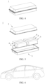
- FIG. 4 and FIG. 5 show a battery pack 1 as an example.
- the battery pack 1 may include a battery box and a plurality of battery modules 4 arranged in the battery box.
- the battery box includes an upper box body 2 and a lower box body 3.
- the upper box body 2 can cover the lower box body 3 to form enclosed space for accommodating the battery modules 4.
- the plurality of battery modules 4 may be arranged in the battery box in any manner.
- This application further provides a preparation method of a secondary battery.
- the preparation method includes steps of preparing a positive electrode plate: providing a positive electrode active material, where the positive electrode active material includes a first material and a second material, the first material contains lithium transition metal oxide, the second material contains lithium transition metal phosphate, the lithium transition metal phosphate includes secondary particles formed by agglomeration of primary particles, and the second material has a lower discharge platform voltage than the first material with respect to a same type of counter electrode; forming the positive electrode active material into a positive electrode slurry; and applying the positive electrode slurry onto a positive electrode current collector to form a positive electrode film layer, to obtain the positive electrode plate.
- the first material and the second material may be the materials described herein.
- the positive electrode active material, the optional conductive agent, and the optional binder can be dispersed in a solvent (for example, N-methylpyrrolidone NMP), and stirred evenly to form the positive electrode slurry. Then the positive electrode slurry can be applied onto at least one surface of the positive electrode current collector in a coating method well-known in the art. A positive electrode slurry coating layer is dried and cold pressed to form a positive electrode film layer to obtain the positive electrode plate.
- a solvent for example, N-methylpyrrolidone NMP
- viscosity of the positive electrode slurry ranges from 3000 mPa s to 30000 mPa ⁇ s, for example, from 3000 mPa ⁇ s to 20000 mPa ⁇ s, from 4000 mPa ⁇ s to 15000 mPa ⁇ s, from 6000 mPa ⁇ s to 15000 mPa s, or from 6000 mPa s to 10000 mPa s.
- the viscosity of the positive electrode slurry is within the foregoing range, so that processability of the slurry and the film layer can be improved, thereby improving processing efficiency and electrochemical performance of the secondary battery.
- the positive electrode slurry is left standing for 48 hours during which no or almost no gelation, delamination, or sedimentation occurs.
- the slurry can be scooped up (by using, for example, a stainless steel ruler or a stainless steel plate), and the slurry flows down naturally. If it is determined, through visual observation, that the slurry continuously flows and that there is no agglomerate in the slurry, the slurry is not gelled. It can be determined, through visual observation, whether the positive electrode slurry is delaminated and sedimented.
- the positive electrode slurry has good stability, which facilitates preparation of an even positive electrode film layer.
- the preparation method in this application may further include other well-known steps for preparing the secondary battery. Details are not described herein.
- the negative electrode plate in this application can be prepared in the following preparation method: The negative electrode active material and the optional conductive agent, the optional binder and another optional additive are mixed and then dispersed in a solvent (for example, NMP or deionized water), stirred evenly, then applied onto the negative electrode current collector, dried and cold pressed, to obtain the negative electrode plate.
- a solvent for example, NMP or deionized water
- materials such as the positive electrode active material and the negative electrode active material for preparing the secondary battery can be obtained commercially or prepared in a method known in the art.
- a person skilled in the art can make a proper choice according to an actual use need.
- the positive electrode plate, the negative electrode plate, the separator, and the electrolyte can be assembled into the secondary battery.
- the positive electrode plate, the separator, and the negative electrode plate can be wound or stacked to form the electrode assembly; and the electrode assembly is put in an outer package, and an electrolyte is injected, and then subjected to treatment such as vacuum packaging, standing, formation, and shaping to obtain the secondary battery.
- a preferable technical feature of the secondary battery in this application are also applicable to the preparation method in this application, implementing corresponding beneficial effects.
- the apparatus includes at least one of the secondary battery, the battery module, or the battery pack in this application.
- the secondary battery, the battery module, or the battery pack may be used as a power source for the apparatus, or an energy storage unit of the apparatus.
- the apparatus may be, but is not limited to, a mobile device (for example, a mobile phone or a notebook computer), an electric vehicle (for example, a full electric vehicle, a hybrid electric vehicle, a plug-in hybrid electric vehicle, an electric bicycle, an electric scooter, an electric golf vehicle, or an electric truck), an electric train, a ship, a satellite, an energy storage system, and the like.
- the secondary battery, the battery module, or the battery pack may be selected for the apparatus based on requirements for using the apparatus.
- FIG. 6 shows an apparatus as an example.
- the apparatus is a full electric vehicle, a hybrid electric vehicle, a plug-in hybrid electric vehicle, or the like.
- a battery pack or a battery module may be used.
- the apparatus may be a mobile phone, a tablet computer, a notebook computer, or the like.
- the apparatus is usually required to be light and thin, and the secondary battery may be used as a power source.
- a positive electrode active material applied to the following examples and comparative examples are commercially available.
- a first material NCM-1 and a second material LFP/C were mixed to obtain a positive electrode active material; the positive electrode active material, a conductive agent conductive carbon black, and a binder polyvinylidene fluoride (PVDF) were mixed at a mass ratio of 95:3:2 in a solvent NMP and well stirred evenly to form an even positive electrode slurry.
- the positive electrode slurry was applied onto two side surfaces of aluminum foil of a positive electrode current collector, followed by drying and cold pressing, to obtain the positive electrode plate. Compacted density of the positive electrode film layer was 3.22 g/cm 3 .
- a negative electrode active material artificial graphite, a conductive agent conductive carbon black, a binder styrene-butadiene rubber (SBR), a thickener sodium carboxymethyl cellulose (CMC-Na) were well stirred and mixed in a deionized water solvent at a mass ratio of 95:2:2:1, to form an even negative electrode slurry.
- the negative electrode slurry was applied onto two side surfaces of copper foil of a negative electrode current collector, followed by drying and cold pressing, to obtain the negative electrode plate. Compacted density of the negative electrode film layer was 1.5 g/cm 3 .
- Ethylene carbonate EC and propylene carbonate PC of an equal volume were mixed evenly to obtain a solvent; and then an electrolyte lithium salt LiPF 6 was dissolved in the solvent and mixed evenly, to obtain the electrolyte, where a concentration of LiPF 6 was 1 mol/L.
- the positive electrode plate, a porous polyethylene (PE) separator, and the negative electrode plate were stacked in order and then wound to obtain an electrode assembly; and the electrode assembly was put in an outer package of an aluminum hard shell, and the electrolyte was injected and then packaged, to obtain a secondary battery.
- a capacity of the secondary battery was 60 Ah.
- a ratio W of a discharge platform capacity of the second material to a total discharge capacity of the positive electrode active material was equal to 5%.
- Testing an actual capacity Co of the secondary battery at 25°C includes: The battery was left standing for 2 hours, discharged to a lower cut-off voltage at a constant current at a rate of 0.33C (for details, refer to Table 2), and left standing for 10 minutes; and then the secondary battery was (1C indicated current intensity for completely discharging a nominal capacity of the secondary battery within 1 hour) charged at a constant current at 0.33C to an upper cut-off voltage of 4.35 V, then charged at a constant voltage until a current was ⁇ 0.05C, left standing for 10 minutes, and then discharged to the lower cut-off voltage at a constant current at 0.33C. An actual capacity was recorded as Co.
- the battery was charged at a constant current at a rate of 0.33C 0 to the upper cut-off voltage of 4.35 V, and then charged at a constant voltage until the current was ⁇ 0.05C; at that point, the battery was at 100% SOC and then was left standing for 10 minutes; and then the battery was discharged with a constant current at a rate of 0.33Co to 5% SOC, and left standing for 10 minutes; temperature was adjusted to target test temperature, for example, 25°C or -20°C, the battery was left standing for 2 hours, where a discharge current was based on a pulse current satisfying that the lower cut-off voltage could be reached during 10 seconds of discharge at 25°C or -20°C; and the battery was left standing for 10 minutes to obtain DCR of the battery at 5% SOC, and that DCR was recorded as DCR@5% SOC.
- DCR@5% SOC of the battery containing only the first material in this example was recorded as DCR0
- DCR@5% SOC of the tested battery was recorded as DCR1
- direct current internal resistance DCR improvement ratio (%) of the battery at the 5% SOC (DCR1 - DCR0)/DCR0 ⁇ 100%.
- DCR0 and DCR1 were measured under the same temperature.
- the cycling swelling force growth rate was obtained by dividing an average swelling force change ⁇ F by N, where ⁇ F was caused when a cycling charge/discharge capacity of the secondary battery dropped to 90% (that is, 90% SOH) of a nominal capacity (the number of cycles at that point was recorded as N) at 25°C at a rate of 0.33C within a range of the upper cut-off voltage of 4.35 V to the lower cut-off voltage (refer to Table 2) of the secondary battery, and ⁇ F was a change in pressure of the secondary battery detected by a sensor in a detection apparatus at the N th cycle of the secondary battery with respect to that at a start of cycling.
- FIG. 7 and FIG. 8 show a detection apparatus 10. As shown in FIG. 7 and FIG. 8 , the detection apparatus 10 includes a clamp assembly 11 and a pressure sensor 12.
- the clamp assembly 11 includes three steel plate clamps, the to-be-tested secondary battery is clamped between two clamps, and wide surfaces of the secondary battery are in a face-to-face contact with the steel plate clamps; and the pressure sensor 12 is clamped between another clamp and either of the foregoing two clamps, and the pressure sensor 12 is connected to a pressure collector (for example, a computer).
- a thickness of a steel plate is 30 mm.
- the steel plates and a connection member between the steel plates may be made of steel 45, and further, a surface of the steel plate may be coated with chrome.
- a diameter of a pretensioner between the steel plates is optionally 15 mm.
- Pre-tightening force was applied onto the to-be-tested secondary battery through the steel plate clamps (for example, when the secondary battery was a hard shell battery, 3 kN pre-tightening force could be selected; or when the secondary battery was a pouch-type battery, 1 kN pre-tightening force could be selected), and was maintained throughout a test procedure, and the pre-tightening force was recorded as initial swelling force Fo of the to-be-tested secondary battery.
- the secondary battery and the pressure sensor could be clamped in the center of the clamps, and the pretensioners (for example, screws) at the four corners of the clamps were fastened alternately diagonally, and finally, the pretensioners at the four corners were fine tuned to achieve required pre-tightening force. Then, the secondary battery was charged at a constant current at 0.33C to the upper cut-off voltage at ambient temperature set to 25°C, then charged at a constant voltage until a current was less than 0.05C, left standing for 10 minutes, and then discharged at a constant current at 0.33C to the lower cut-off voltage, and this was denoted as a cycle.
- the pretensioners for example, screws
- the secondary battery was charged and discharged cyclically in this way, and a discharge capacity and swelling force of the secondary battery were monitored in real time until the discharge capacity of the battery attenuated to 90% of the nominal capacity. Finally, a cycling swelling force growth rate of the secondary battery was calculated according to ⁇ F/N.
- Example 1 Number First material Second material W Type D V 50 ( ⁇ m) D V 99/D V 10 D N 10 ( ⁇ m) Ratio of single particles U1 (V) Type Ratio of secondary particles Particle size of primary particles (nm) D V 50 ( ⁇ m) Carbon content (wt%) U2 (V)
- Example 1 NCM-1 3.7 4.2 0.65 90% 3.77 LFP/C 100% 350 5.8 1.47 3.22 5%
- Example 2 NCM-2 3.7 4.2 0.65 90% 3.75 LFP/C 100% 350 5.8 1.47 3.22 5%
- Example 3 NCM-3 3.7 4.2 0.65 90% 3.75 LFP/C 100% 350 5.8 1.47 3.22 5%
- Example 4 NCM-4 3.7 4.2 0.65 90% 3.76 LFP/C 100% 350 5.8 1.47 3.22 5%
- Example 5 NCM-4 3.7 4.2 0.65 90% 3.76 LFP/C 100% 350 5.8 1.47 3.22 1%
- Example 6 NCM-4 3.7 4.2 0.65 90% 3.76 LFP/C 100% 350 5.8 1.47 3.22
- the positive electrode plate included the first material, and the first material contained the lithium transition metal oxide.
- the positive electrode plate was also combined with the second material, the second material contained lithium transition metal phosphate, the lithium transition metal phosphate included secondary particles, the second material had a lower discharge platform voltage than the first material, and therefore, the direct current internal resistance of the battery could be greatly increased under higher energy density of the battery, and particularly, the direct current internal resistance of the battery at low temperature or a low SOC is more obviously increased.
- the battery could also have a lower cycling swelling force change rate.
Landscapes
- Chemical & Material Sciences (AREA)
- Chemical Kinetics & Catalysis (AREA)
- Electrochemistry (AREA)
- General Chemical & Material Sciences (AREA)
- Inorganic Chemistry (AREA)
- Engineering & Computer Science (AREA)
- Manufacturing & Machinery (AREA)
- Composite Materials (AREA)
- Materials Engineering (AREA)
- Crystallography & Structural Chemistry (AREA)
- Battery Electrode And Active Subsutance (AREA)
Priority Applications (1)
| Application Number | Priority Date | Filing Date | Title |
|---|---|---|---|
| EP24182464.8A EP4407714A3 (de) | 2020-08-31 | 2020-08-31 | Sekundärbatterie und herstellungsverfahren dafür sowie batteriemodul, batteriepack und vorrichtung mit der sekundärbatterie |
Applications Claiming Priority (3)
| Application Number | Priority Date | Filing Date | Title |
|---|---|---|---|
| EP24182464.8A EP4407714A3 (de) | 2020-08-31 | 2020-08-31 | Sekundärbatterie und herstellungsverfahren dafür sowie batteriemodul, batteriepack und vorrichtung mit der sekundärbatterie |
| PCT/CN2020/112703 WO2022041259A1 (zh) | 2020-08-31 | 2020-08-31 | 二次电池及其制备方法与包含二次电池的电池模块、电池包及装置 |
| EP20950928.0A EP4075538B1 (de) | 2020-08-31 | 2020-08-31 | Sekundärbatterie und herstellungsverfahren dafür sowie batteriemodul, batteriepack und vorrichtung mit der sekundärbatterie |
Related Parent Applications (1)
| Application Number | Title | Priority Date | Filing Date |
|---|---|---|---|
| EP20950928.0A Division EP4075538B1 (de) | 2020-08-31 | 2020-08-31 | Sekundärbatterie und herstellungsverfahren dafür sowie batteriemodul, batteriepack und vorrichtung mit der sekundärbatterie |
Publications (2)
| Publication Number | Publication Date |
|---|---|
| EP4407714A2 true EP4407714A2 (de) | 2024-07-31 |
| EP4407714A3 EP4407714A3 (de) | 2024-10-23 |
Family
ID=80354390
Family Applications (2)
| Application Number | Title | Priority Date | Filing Date |
|---|---|---|---|
| EP20950928.0A Active EP4075538B1 (de) | 2020-08-31 | 2020-08-31 | Sekundärbatterie und herstellungsverfahren dafür sowie batteriemodul, batteriepack und vorrichtung mit der sekundärbatterie |
| EP24182464.8A Pending EP4407714A3 (de) | 2020-08-31 | 2020-08-31 | Sekundärbatterie und herstellungsverfahren dafür sowie batteriemodul, batteriepack und vorrichtung mit der sekundärbatterie |
Family Applications Before (1)
| Application Number | Title | Priority Date | Filing Date |
|---|---|---|---|
| EP20950928.0A Active EP4075538B1 (de) | 2020-08-31 | 2020-08-31 | Sekundärbatterie und herstellungsverfahren dafür sowie batteriemodul, batteriepack und vorrichtung mit der sekundärbatterie |
Country Status (5)
| Country | Link |
|---|---|
| US (1) | US20230016240A1 (de) |
| EP (2) | EP4075538B1 (de) |
| CN (1) | CN114982002A (de) |
| HU (1) | HUE068287T2 (de) |
| WO (1) | WO2022041259A1 (de) |
Families Citing this family (21)
| Publication number | Priority date | Publication date | Assignee | Title |
|---|---|---|---|---|
| CN117957685A (zh) * | 2022-06-24 | 2024-04-30 | 宁德时代新能源科技股份有限公司 | 电池包和用电装置 |
| CN115020696B (zh) * | 2022-07-12 | 2024-08-20 | 远景动力技术(江苏)有限公司 | 正极活性材料、电化学装置和电子设备 |
| CN115810728B (zh) * | 2022-10-12 | 2025-01-10 | 宁德时代新能源科技股份有限公司 | 正极材料、正极浆料、正极极片、二次电池及用电装置 |
| CN118970187A (zh) * | 2022-10-17 | 2024-11-15 | 宁德时代新能源科技股份有限公司 | 二次电池以及包含其的用电装置 |
| CN118315528A (zh) * | 2023-01-09 | 2024-07-09 | 宁德时代新能源科技股份有限公司 | 电芯、电池以及用电设备 |
| CN117355974A (zh) * | 2023-02-23 | 2024-01-05 | 宁德时代新能源科技股份有限公司 | 二次电池及包含其的用电装置 |
| KR20250121156A (ko) * | 2023-03-07 | 2025-08-11 | 컨템포러리 엠퍼렉스 테크놀로지 (홍콩) 리미티드 | 양극재 조성물, 이차 배터리 및 전기 장치 |
| CN116759568B (zh) * | 2023-03-10 | 2025-01-14 | 宁德时代新能源科技股份有限公司 | 一种电池和用电装置 |
| CN118693239B (zh) * | 2023-03-21 | 2026-01-27 | 宁德时代新能源科技股份有限公司 | 正极活性物质、正极极片、二次电池和用电装置 |
| WO2024197518A1 (zh) * | 2023-03-27 | 2024-10-03 | 宁德时代新能源科技股份有限公司 | 正极材料、正极极片、二次电池及用电装置 |
| EP4697424A1 (de) * | 2023-04-18 | 2026-02-18 | Contemporary Amperex Technology Co., Limited | Sekundärbatterie und elektrische vorrichtung |
| CN119108517A (zh) * | 2023-06-09 | 2024-12-10 | 宁德时代新能源科技股份有限公司 | 正极活性物质、电池单体、电池和用电装置 |
| KR20250000748A (ko) * | 2023-06-27 | 2025-01-03 | 에스케이온 주식회사 | 리튬 이차전지 |
| CN119852342B (zh) * | 2024-01-08 | 2026-03-17 | 宁德时代新能源科技股份有限公司 | 二次电池、其制备方法和用电装置 |
| CN120709364A (zh) * | 2024-03-25 | 2025-09-26 | 宁德时代新能源科技股份有限公司 | 复合材料及其制备方法、正极极片、二次电池和用电装置 |
| KR20250155267A (ko) * | 2024-04-23 | 2025-10-30 | 삼성에스디아이 주식회사 | 리튬 이차 전지용 양극 활물질, 이의 제조 방법 및 이를 포함하는 리튬 이차 전지 |
| CN120016033A (zh) * | 2024-08-08 | 2025-05-16 | 宁德时代新能源科技股份有限公司 | 电池单体、电池装置及用电装置 |
| CN119852486A (zh) * | 2024-10-29 | 2025-04-18 | 宁德时代新能源科技股份有限公司 | 二次电池和用电装置 |
| CN119852484A (zh) * | 2024-10-29 | 2025-04-18 | 宁德时代新能源科技股份有限公司 | 二次电池和用电装置 |
| CN119852485A (zh) * | 2024-10-29 | 2025-04-18 | 宁德时代新能源科技股份有限公司 | 二次电池和用电装置 |
| CN119833717A (zh) * | 2025-01-02 | 2025-04-15 | 宁德时代新能源科技股份有限公司 | 锂离子二次电池及其充电方法、用电装置 |
Family Cites Families (8)
| Publication number | Priority date | Publication date | Assignee | Title |
|---|---|---|---|---|
| CN102117913A (zh) * | 2009-12-31 | 2011-07-06 | 珠海光宇电池有限公司 | 使用混合正极材料的动力电池 |
| US20120231341A1 (en) * | 2011-03-09 | 2012-09-13 | Jun-Sik Kim | Positive active material, and electrode and lithium battery containing the positive active material |
| WO2013129182A1 (ja) * | 2012-02-29 | 2013-09-06 | 新神戸電機株式会社 | リチウムイオン電池 |
| CN104300123B (zh) * | 2014-03-20 | 2017-05-31 | 中航锂电(江苏)有限公司 | 一种混合正极材料、使用该正极材料的正极片及锂离子电池 |
| CN105185987B (zh) * | 2014-05-29 | 2017-09-12 | 宁德新能源科技有限公司 | 正极材料及锂离子二次电池 |
| KR102226429B1 (ko) * | 2018-02-19 | 2021-03-10 | 삼성에스디아이 주식회사 | 리튬 이차 전지용 양극 활물질, 이를 포함하는 양극 및 이를 포함하는 리튬 이차 전지 |
| WO2020163522A1 (en) * | 2019-02-05 | 2020-08-13 | EnPower, Inc. | Multilayered electrodes having high charge and discharge rates |
| CN111446488B (zh) * | 2020-04-30 | 2025-02-18 | 宁德时代新能源科技股份有限公司 | 一种二次电池及其装置 |
-
2020
- 2020-08-31 EP EP20950928.0A patent/EP4075538B1/de active Active
- 2020-08-31 EP EP24182464.8A patent/EP4407714A3/de active Pending
- 2020-08-31 HU HUE20950928A patent/HUE068287T2/hu unknown
- 2020-08-31 CN CN202080093643.9A patent/CN114982002A/zh active Pending
- 2020-08-31 WO PCT/CN2020/112703 patent/WO2022041259A1/zh not_active Ceased
-
2022
- 2022-09-09 US US17/942,022 patent/US20230016240A1/en active Pending
Also Published As
| Publication number | Publication date |
|---|---|
| EP4075538A1 (de) | 2022-10-19 |
| HUE068287T2 (hu) | 2024-12-28 |
| EP4407714A3 (de) | 2024-10-23 |
| US20230016240A1 (en) | 2023-01-19 |
| EP4075538A4 (de) | 2023-01-25 |
| CN114982002A (zh) | 2022-08-30 |
| WO2022041259A1 (zh) | 2022-03-03 |
| EP4075538B1 (de) | 2024-07-03 |
Similar Documents
| Publication | Publication Date | Title |
|---|---|---|
| EP4075538B1 (de) | Sekundärbatterie und herstellungsverfahren dafür sowie batteriemodul, batteriepack und vorrichtung mit der sekundärbatterie | |
| US11804590B2 (en) | Secondary battery, preparation method thereof, and battery module, battery pack, and apparatus containing secondary battery | |
| CN111446488B (zh) | 一种二次电池及其装置 | |
| EP3968407B1 (de) | Sekundärbatterie und herstellungsverfahren dafür sowie vorrichtung mit einer sekundärbatterie | |
| EP3968430B1 (de) | Sekundärbatterie und vorrichtung mit der sekundärbatterie batterie | |
| EP4064385A1 (de) | Sekundärbatterie, herstellungsverfahren dafür, batteriemodul, batteriepack und vorrichtung | |
| EP4145564A1 (de) | Sekundärbatterie und herstellungsverfahren dafür, batteriemodul mit sekundärbatterie, batteriepack und vorrichtung | |
| US20230261175A1 (en) | Positive electrode active material and related electrode sheet, secondary battery, battery module, battery pack and apparatus thereof | |
| US11605816B2 (en) | Lithium secondary battery and battery module, battery pack, and electric apparatus containing same | |
| EP3965201A1 (de) | Sekundärbatterie und vorrichtung damit | |
| EP4312288A1 (de) | Positivelektrodenplatte für lithium-ionen-batterie sowie lithium-ionen-batterie und elektrische vorrichtung damit | |
| EP4020691B1 (de) | Batteriemodul, batteriepack, gerät sowie verfahren und vorrichtung zur herstellung eines batteriemoduls | |
| US9172083B2 (en) | Lithium ion secondary battery | |
| EP4239717A1 (de) | Positivelektrodenplatte, sekundärbatterie, batteriemodul, batteriepack und elektrische vorrichtung | |
| US11682788B2 (en) | Secondary battery and apparatus containing such secondary battery | |
| EP4047712A1 (de) | Batteriesatz, batteriepack, elektrisches gerät sowie herstellungsverfahren und herstellungsvorrichtung für batteriesatz | |
| EP4611056A1 (de) | Negativelektrodenfolie und elektrodenanordnung damit, batteriezelle, batterie und elektrische vorrichtung | |
| EP4451377A1 (de) | Sekundärbatterie, batteriemodul, batteriepack und elektrische vorrichtung | |
| EP4503173A1 (de) | Negativelektrodenplatte und herstellungsverfahren dafür, sekundärbatterie, batteriemodul, batteriepack und elektrische vorrichtung | |
| EP4235832A1 (de) | Positivelektrodenverbundmaterial für lithium-ionen-sekundärbatterie, positivelektrode und batterie | |
| US20230207823A1 (en) | Secondary battery and electric apparatus containing same | |
| CN115832187B (zh) | 电极及其制备方法、二次电池、电池模块、电池包和用电装置 | |
| EP4645477A1 (de) | Positivelektrodenfolie, batterie und elektrische vorrichtung | |
| EP4597621A1 (de) | Positivelektrodenaktivmaterial, positivelektrodenfolie, batteriezelle, batterie und elektrische vorrichtung | |
| EP4564447A1 (de) | Batteriezelle und herstellungsverfahren dafür, sekundärbatterie und elektrische vorrichtung |
Legal Events
| Date | Code | Title | Description |
|---|---|---|---|
| PUAI | Public reference made under article 153(3) epc to a published international application that has entered the european phase |
Free format text: ORIGINAL CODE: 0009012 |
|
| STAA | Information on the status of an ep patent application or granted ep patent |
Free format text: STATUS: REQUEST FOR EXAMINATION WAS MADE |
|
| 17P | Request for examination filed |
Effective date: 20240617 |
|
| AC | Divisional application: reference to earlier application |
Ref document number: 4075538 Country of ref document: EP Kind code of ref document: P |
|
| AK | Designated contracting states |
Kind code of ref document: A2 Designated state(s): AL AT BE BG CH CY CZ DE DK EE ES FI FR GB GR HR HU IE IS IT LI LT LU LV MC MK MT NL NO PL PT RO RS SE SI SK SM TR |
|
| REG | Reference to a national code |
Ref country code: DE Ref legal event code: R079 Free format text: PREVIOUS MAIN CLASS: H01M0004525000 Ipc: H01M0004130000 |
|
| PUAL | Search report despatched |
Free format text: ORIGINAL CODE: 0009013 |
|
| RAP1 | Party data changed (applicant data changed or rights of an application transferred) |
Owner name: CONTEMPORARY AMPEREX TECHNOLOGY(HONG KONG) LIMITED |
|
| AK | Designated contracting states |
Kind code of ref document: A3 Designated state(s): AL AT BE BG CH CY CZ DE DK EE ES FI FR GB GR HR HU IE IS IT LI LT LU LV MC MK MT NL NO PL PT RO RS SE SI SK SM TR |
|
| RIC1 | Information provided on ipc code assigned before grant |
Ipc: H01M 4/525 20100101ALI20240917BHEP Ipc: H01M 4/505 20100101ALI20240917BHEP Ipc: H01M 4/48 20100101ALI20240917BHEP Ipc: H01M 4/36 20060101ALI20240917BHEP Ipc: H01M 4/1391 20100101ALI20240917BHEP Ipc: H01M 4/04 20060101ALI20240917BHEP Ipc: H01M 10/0525 20100101ALI20240917BHEP Ipc: H01M 4/13 20100101AFI20240917BHEP |
|
| STAA | Information on the status of an ep patent application or granted ep patent |
Free format text: STATUS: EXAMINATION IS IN PROGRESS |
|
| 17Q | First examination report despatched |
Effective date: 20251208 |