EP4407571A1 - Zellerkennungsverfahren, -vorrichtung und -system - Google Patents
Zellerkennungsverfahren, -vorrichtung und -system Download PDFInfo
- Publication number
- EP4407571A1 EP4407571A1 EP22872210.4A EP22872210A EP4407571A1 EP 4407571 A1 EP4407571 A1 EP 4407571A1 EP 22872210 A EP22872210 A EP 22872210A EP 4407571 A1 EP4407571 A1 EP 4407571A1
- Authority
- EP
- European Patent Office
- Prior art keywords
- cell
- information
- cellular
- traction force
- cells
- Prior art date
- Legal status (The legal status is an assumption and is not a legal conclusion. Google has not performed a legal analysis and makes no representation as to the accuracy of the status listed.)
- Pending
Links
Images


Classifications
-
- G—PHYSICS
- G06—COMPUTING OR CALCULATING; COUNTING
- G06N—COMPUTING ARRANGEMENTS BASED ON SPECIFIC COMPUTATIONAL MODELS
- G06N3/00—Computing arrangements based on biological models
- G06N3/02—Neural networks
- G06N3/08—Learning methods
-
- G—PHYSICS
- G01—MEASURING; TESTING
- G01N—INVESTIGATING OR ANALYSING MATERIALS BY DETERMINING THEIR CHEMICAL OR PHYSICAL PROPERTIES
- G01N15/00—Investigating characteristics of particles; Investigating permeability, pore-volume or surface-area of porous materials
- G01N15/10—Investigating individual particles
- G01N15/14—Optical investigation techniques, e.g. flow cytometry
- G01N15/1429—Signal processing
-
- G—PHYSICS
- G01—MEASURING; TESTING
- G01N—INVESTIGATING OR ANALYSING MATERIALS BY DETERMINING THEIR CHEMICAL OR PHYSICAL PROPERTIES
- G01N15/00—Investigating characteristics of particles; Investigating permeability, pore-volume or surface-area of porous materials
- G01N15/01—Investigating characteristics of particles; Investigating permeability, pore-volume or surface-area of porous materials specially adapted for biological cells, e.g. blood cells
-
- G—PHYSICS
- G01—MEASURING; TESTING
- G01N—INVESTIGATING OR ANALYSING MATERIALS BY DETERMINING THEIR CHEMICAL OR PHYSICAL PROPERTIES
- G01N15/00—Investigating characteristics of particles; Investigating permeability, pore-volume or surface-area of porous materials
- G01N15/10—Investigating individual particles
- G01N15/1023—Microstructural devices for non-optical measurement
-
- G—PHYSICS
- G01—MEASURING; TESTING
- G01N—INVESTIGATING OR ANALYSING MATERIALS BY DETERMINING THEIR CHEMICAL OR PHYSICAL PROPERTIES
- G01N19/00—Investigating materials by mechanical methods
- G01N19/04—Measuring adhesive force between materials, e.g. of sealing tape, of coating
-
- G—PHYSICS
- G01—MEASURING; TESTING
- G01N—INVESTIGATING OR ANALYSING MATERIALS BY DETERMINING THEIR CHEMICAL OR PHYSICAL PROPERTIES
- G01N3/00—Investigating strength properties of solid materials by application of mechanical stress
- G01N3/08—Investigating strength properties of solid materials by application of mechanical stress by applying steady tensile or compressive forces
-
- G—PHYSICS
- G01—MEASURING; TESTING
- G01N—INVESTIGATING OR ANALYSING MATERIALS BY DETERMINING THEIR CHEMICAL OR PHYSICAL PROPERTIES
- G01N33/00—Investigating or analysing materials by specific methods not covered by groups G01N1/00 - G01N31/00
- G01N33/48—Biological material, e.g. blood, urine; Haemocytometers
- G01N33/483—Physical analysis of biological material
- G01N33/4833—Physical analysis of biological material of solid biological material, e.g. tissue samples, cell cultures
-
- G—PHYSICS
- G06—COMPUTING OR CALCULATING; COUNTING
- G06N—COMPUTING ARRANGEMENTS BASED ON SPECIFIC COMPUTATIONAL MODELS
- G06N20/00—Machine learning
-
- G—PHYSICS
- G06—COMPUTING OR CALCULATING; COUNTING
- G06N—COMPUTING ARRANGEMENTS BASED ON SPECIFIC COMPUTATIONAL MODELS
- G06N20/00—Machine learning
- G06N20/10—Machine learning using kernel methods, e.g. support vector machines [SVM]
-
- G—PHYSICS
- G06—COMPUTING OR CALCULATING; COUNTING
- G06N—COMPUTING ARRANGEMENTS BASED ON SPECIFIC COMPUTATIONAL MODELS
- G06N3/00—Computing arrangements based on biological models
- G06N3/02—Neural networks
- G06N3/04—Architecture, e.g. interconnection topology
- G06N3/0464—Convolutional networks [CNN, ConvNet]
-
- G—PHYSICS
- G06—COMPUTING OR CALCULATING; COUNTING
- G06V—IMAGE OR VIDEO RECOGNITION OR UNDERSTANDING
- G06V10/00—Arrangements for image or video recognition or understanding
- G06V10/70—Arrangements for image or video recognition or understanding using pattern recognition or machine learning
- G06V10/764—Arrangements for image or video recognition or understanding using pattern recognition or machine learning using classification, e.g. of video objects
-
- G—PHYSICS
- G06—COMPUTING OR CALCULATING; COUNTING
- G06V—IMAGE OR VIDEO RECOGNITION OR UNDERSTANDING
- G06V20/00—Scenes; Scene-specific elements
- G06V20/60—Type of objects
- G06V20/69—Microscopic objects, e.g. biological cells or cellular parts
-
- G—PHYSICS
- G01—MEASURING; TESTING
- G01N—INVESTIGATING OR ANALYSING MATERIALS BY DETERMINING THEIR CHEMICAL OR PHYSICAL PROPERTIES
- G01N15/00—Investigating characteristics of particles; Investigating permeability, pore-volume or surface-area of porous materials
- G01N15/10—Investigating individual particles
- G01N2015/1006—Investigating individual particles for cytology
-
- G—PHYSICS
- G01—MEASURING; TESTING
- G01N—INVESTIGATING OR ANALYSING MATERIALS BY DETERMINING THEIR CHEMICAL OR PHYSICAL PROPERTIES
- G01N15/00—Investigating characteristics of particles; Investigating permeability, pore-volume or surface-area of porous materials
- G01N15/10—Investigating individual particles
- G01N2015/1022—Measurement of deformation of individual particles by non-optical means
-
- G—PHYSICS
- G01—MEASURING; TESTING
- G01N—INVESTIGATING OR ANALYSING MATERIALS BY DETERMINING THEIR CHEMICAL OR PHYSICAL PROPERTIES
- G01N15/00—Investigating characteristics of particles; Investigating permeability, pore-volume or surface-area of porous materials
- G01N15/10—Investigating individual particles
- G01N2015/103—Particle shape
-
- G—PHYSICS
- G01—MEASURING; TESTING
- G01N—INVESTIGATING OR ANALYSING MATERIALS BY DETERMINING THEIR CHEMICAL OR PHYSICAL PROPERTIES
- G01N15/00—Investigating characteristics of particles; Investigating permeability, pore-volume or surface-area of porous materials
- G01N15/10—Investigating individual particles
- G01N15/14—Optical investigation techniques, e.g. flow cytometry
- G01N2015/1497—Particle shape
-
- G—PHYSICS
- G01—MEASURING; TESTING
- G01N—INVESTIGATING OR ANALYSING MATERIALS BY DETERMINING THEIR CHEMICAL OR PHYSICAL PROPERTIES
- G01N2203/00—Investigating strength properties of solid materials by application of mechanical stress
- G01N2203/0058—Kind of property studied
- G01N2203/0089—Biorheological properties
-
- G—PHYSICS
- G01—MEASURING; TESTING
- G01N—INVESTIGATING OR ANALYSING MATERIALS BY DETERMINING THEIR CHEMICAL OR PHYSICAL PROPERTIES
- G01N2203/00—Investigating strength properties of solid materials by application of mechanical stress
- G01N2203/02—Details not specific for a particular testing method
- G01N2203/06—Indicating or recording means; Sensing means
- G01N2203/0641—Indicating or recording means; Sensing means using optical, X-ray, ultraviolet, infrared or similar detectors
-
- G—PHYSICS
- G01—MEASURING; TESTING
- G01N—INVESTIGATING OR ANALYSING MATERIALS BY DETERMINING THEIR CHEMICAL OR PHYSICAL PROPERTIES
- G01N2203/00—Investigating strength properties of solid materials by application of mechanical stress
- G01N2203/02—Details not specific for a particular testing method
- G01N2203/06—Indicating or recording means; Sensing means
- G01N2203/067—Parameter measured for estimating the property
- G01N2203/0676—Force, weight, load, energy, speed or acceleration
-
- G—PHYSICS
- G06—COMPUTING OR CALCULATING; COUNTING
- G06V—IMAGE OR VIDEO RECOGNITION OR UNDERSTANDING
- G06V10/00—Arrangements for image or video recognition or understanding
- G06V10/70—Arrangements for image or video recognition or understanding using pattern recognition or machine learning
- G06V10/82—Arrangements for image or video recognition or understanding using pattern recognition or machine learning using neural networks
Definitions
- the present application relates to the field of cell analysis and identification, particularly to a method, device, and system for cell identification.
- scRNA-seq single-cell sequencing technologies
- scRNA-seq single-cell sequencing technologies
- a limitation of this approach is that it essentially takes a snapshot of the single cell, employing an invasive and destructive method, which does not allow for real-time monitoring of the same cell.
- Other methods, such as immunofluorescence, require staining of the cells, which inevitably affects or damages the cells, with the process being costly and complex.
- the present application providing a method for cell identification, comprising the following steps:
- the cell information comprising cellular traction force information at a point within a cell obtained via a cellular mechanical sensor, the cellular traction force information comprising the magnitude of the cellular traction force at the point; preprocessing the acquired cell information to generate structured cell information, the structured cell information comprising the number of cells, the number of cell features, and feature information for each cell feature; and inputting the structured cell information into a machine learning model established through supervised, unsupervised, or semi-supervised learning, and applying the machine learning model to classify or cluster cells of unknown types or states.
- the cellular traction force information also includes the direction of the cellular traction force at this point.
- the cellular traction force information also includes the changes of the magnitude or direction of the cellular traction force at the point within a certain time interval.
- the cell information also includes cell morphology information.
- the cell information is obtained by performing cell confining operations on the cell.
- the present application also provides a cell identification device, including: an information acquisition unit configured to acquire cell information, the cell information comprising cellular traction force information at a point within a cell obtained via a cellular mechanical sensor, the cellular traction force information comprising the magnitude of the cellular traction force at that point; a preprocessing unit configured to preprocess the cell information to generate structured cell information, the structured cell information comprising the number of cells, the number of cell features, and information for each cell feature; a learning unit configured to use the structured cell information as input data for establishing a cell feature model via supervised, unsupervised, or semi-supervised learning; and an identification unit configured to apply the cell feature model to classify or cluster cells of unknown types or states.
- an information acquisition unit configured to acquire cell information, the cell information comprising cellular traction force information at a point within a cell obtained via a cellular mechanical sensor, the cellular traction force information comprising the magnitude of the cellular traction force at that point
- a preprocessing unit configured to preprocess the cell information to generate structured cell
- the cellular traction force information also includes the direction of the cellular traction force at the point.
- the cellular traction force information also includes the change of the magnitude or direction of the cellular traction force at the point within a certain time interval.
- the cell information also includes cell morphology information.
- the cell information is obtained by performing cell confining operations on the cell.
- the present application also provides a cell identification system, comprising: a cellular mechanical sensor and the above cell identification device.
- the cellular mechanical sensor includes a nano micropillar array, or a cellular traction force detection device with a light-reflective layer on the micropillars .
- a device for detecting cellular mechanical force including: a base; and an micropillar array of multiple micropillars located on the base, the micropillars being deformable in respond to a cellular mechanical force, and the top or the upper portion of the pillar surface of the micropillars having a light-reflective layer.
- the cell identification system further includes a device for acquiring cell morphology information.
- the device for acquiring cell morphology information thereof includes a microscopic camera or a micro camera.
- the cell identification system thereof further includes a cell confining device for performing cell confining operations on the cell.
- the present application also provides a method for detecting cell state comprising: obtaining cellular traction force information using the above method for identification, the above device for identifying cells, or the above system for identifying cells, and analyzing the cell state based on the cellular traction force information; the cell state includes cell adhesion, cell viability, cell differentiation/activation, cell proliferation, and/or cell migration.
- the cells may be individual cells or multicellular aggregates formed by two or more cells.
- the present application is not limited to the various forms formed by individual cells or two or more cells.
- the present application uses a cellular mechanical sensor to obtain cell mechanical information for cell identification, and the cell identification includes not only the type of the cell, but also the state of the cell; the technical solution in the present application has non-invasive effects on living cells, with significant advantages of real-time, high-throughput, and high-resolution; based on the measurement of the cellular traction force of each single cell, the technical solution in the present application can identify different types of cells, and can be further used to detect the influence of cell force on chemotherapy drugs, even cell sorting, which has great application value in biomedicine and medical treatment.
- the technology presented in this application enables the detection of cellular traction force from multicellular aggregates, such as tumor spheroids and organoids. This capability makes it suitable for applications like drug screening and situations that demand the characterization of multicellular aggregates in regenerative medicine, gene editing, precision medicine, organ development, and disease modeling scenarios.
- Labels in the drawing 1, information acquisition unit; 2, preprocessing unit; 3, learning unit; 4, identification unit; 10, cellular mechanical sensor (cellular traction force detection device); 101, base; 102, light signal generation device; 103, micropillars; 104, spectroscope; 1031, light-reflective layer; 20, cell identification device; 201, image/data processing device; 30, cell morphology information acquisition device; 40, cell confinement device;
- a method for cell identification (only based on the magnitude of cellular traction forces, unlabeled) includes the following steps:
- further optimization or improvement can be achieved by processing the multiple-point cellular traction force magnitude data for an individual cell to calculate additional dimensions of information, such as the average cellular traction force magnitude per unit area or the distribution of cellular traction force magnitudes within the cell.
- additional dimensions of information such as the average cellular traction force magnitude per unit area or the distribution of cellular traction force magnitudes within the cell.
- a method for cell identification (only based on the magnitude of cellular traction force, with labeled) includes the following steps:
- optimization or improvement can be carried out in the following manner: For an individual cell, further information processing is performed on the information on the magnitude of the multi-point cellular traction force obtained by the individual cell, such as calculating the average value of the cellular traction force per unit area and the distribution of the cellular traction force in the cell. Such information can be used as a new cell feature and added to the two-dimensional feature matrix described in step S2, that is, to expand the content of P, then through subsequent machine learning to know which feature can better distinguish cells of different types or states.
- a method for cell identification (only based on the magnitude of cellular traction forces, with partial labeled and partial unlabeled) includes the following steps:
- optimization or improvement can be carried out in the following manner: For an individual cell, further information processing is performed on the information on the magnitude of the multi-point cellular traction force of the individual cell, such as calculating the average value of the cellular traction force per unit area and the distribution of the cellular traction force in the cell. Such information can be used as a new cell feature and added to the two-dimensional feature matrix described in step S2, that is, to expand the content of P, then through subsequent machine learning to know which feature can better distinguish cells of different types or states.
- a method for cell identification (based on the magnitude and direction of cellular traction forces, without labeled) includes the following steps:
- the S2 step in the present embodiment processes cell information approximately as follows: Suppose cellular traction force vector data (magnitude and direction) are collected at n points within a cell. These points are denoted as: ( i , i ⁇ ⁇ 1,2, ... n ⁇ ), corresponding to two-dimensional coordinates: ( x t 0 i , y t 0 i ) and ( x t n i , y t n i ), wherein and t n represent the initial and displaced positions of the nano micropillars, respectively.
- each coordinate point should have a scalar information, i.e., the magnitude of the force d .
- the central point can be calculated as: 1 n ⁇ i x i y i .
- FIG. 1 illustrates a schematic diagram for scalar processing of displacement information at a specific point according to the fourth embodiment of the present application.
- Each point represents a location, with the color depth of the points transitioning from light to dark to signify the force magnitude increasing from small to large.
- After determining the cell axis for each cell further quantification of each point is possible: calculating the angle between each point's displacement vector and the cell axis.
- optimizations or improvements can be made as follows: For individual cell, further processing of the collected data on cellular traction force magnitude or direction, such as calculating the average magnitude of cellular traction force per unit area, distribution of cellular traction force magnitude within the cell and distribution of cellular traction force vectors within the cell, etc., can serve as new cell features to be added to the two-dimensional feature matrix described in step S2, thereby expanding the content of P. Subsequent machine learning can then determine which features better distinguish cells of different types or states.
- FIG.s 2 and 3 show the results of applying the established cell feature model to the identification of unknown cells or cell phenotypes in an extended implementation of the fifth embodiment of the present application.
- the result diagram A ( FIG. 2 ) shows different rows representing different cell types, and different columns representing different samples.
- the black dots represent the top 50 significant features extracted using the Random Forest algorithm, also referred to as significant points. These points denote specific positions within a cell, from which varying cellular traction force information is obtained.
- the result diagram B ( FIG. 3 ) displays the distinctive differentiation effects of using the top 50 significant features (significant points) on three different cell types.
- the significant features learned from labeled data enable dimensionality reduction and visualization of the data. Subsequent cluster algorithms, based on reduced dimensionality data, can be used for cell classification and identification.
- optimizations or improvements can be made as follows: For individual cells, further processing of the collected data on cellular traction force magnitude or direction, such as calculating the average magnitude of cellular traction force per unit area, the distribution of cellular traction force magnitude within the cell and the distribution of cellular traction force vectors within the cell; etc., can serve as new cell features to be added to the two-dimensional feature matrix described in step S2, thereby expanding the content of P. Subsequent machine learning can then determine which features better distinguish cells of different types or states.
- a method for cell identification (magnitude and direction of cellular traction force, with data partially labeled and partially unlabeled), involving the following steps:
- optimizations or improvements can be made as follows: For individual cells, further processing of the collected data on cellular traction force magnitude or direction, such as calculating the average magnitude of cellular traction force per unit area, the distribution of cellular traction force magnitude within the cell and the distribution of cellular traction force vectors within the cell, etc., can serve as new cell features to be added to the two-dimensional feature matrix described in step S2, thereby expanding the content of P. Subsequent machine learning can then determine which features better distinguish cells of different types or states .
- a method for cell identification includes the following steps:
- the mechanical data for individual cells can effectively be analogized to images (instantaneous values) or videos (changes over time). If the array of points covered by the current cell is likened to pixels in an image, and the information recorded at each point (force magnitude, direction, etc.) is analogized to the colors corresponding to pixels, subsequent machine learning can draw on algorithms used in the image and video data processing domains. Specifically, this may involve employing machine learning algorithms widely used in image recognition, more precisely, deep learning, such as Convolutional Neural Networks (CNN), for data modeling and analysis.
- CNN Convolutional Neural Networks
- a method for cell identification includes the following steps:
- the present embodiment's methodology capturing not only the instantaneous values of cellular traction force vectors at specific points but also the changes thereof within a certain time interval, and then the mechanical data of a single cell can be analogized to images (instantaneous values) or videos (changes over time). If the array of points covered by the current cell is likened to pixels in an image, and the information recorded at each point (force magnitude, direction, etc.) is analogized to the colors corresponding to pixels, subsequent machine learning can draw on algorithms used in the image and video data processing domains. Specifically, this may involve employing machine learning algorithms widely used in image recognition, more precisely, deep learning, such as Convolutional Neural Networks (CNN), for data modeling and analysis.
- CNN Convolutional Neural Networks
- a method for cell identification incorporating instantaneous values and changes within a certain time interval of cellular traction force vectors, with partially labeled and partially unlabeled data includes the steps of:
- the mechanical data for individual cells can effectively be analogized to images (instantaneous values) or videos (changes over time). If the array of points covered by the current cell is likened to pixels in an image, and the information recorded at each point (force magnitude, direction, etc.) is analogized to the colors corresponding to pixels, subsequent machine learning can draw on algorithms used in the image and video data processing domains. Specifically, this may involve employing machine learning algorithms widely used in image recognition, more precisely, deep learning, such as Convolutional Neural Networks (CNN), for data modeling and analysis.
- CNN Convolutional Neural Networks
- a cell identification method differs from the first to ninth embodiments by including cell morphological information in the cell data.
- the morphological information is captured using a microscope camera or a microscope video camera, particularly when continuous data collection within a certain time interval is required.
- cell features now also encompass cell morphological information or further information derived from processing or analyzing the morphological data. This includes one or several of the following: cell size, cell shape, nucleus size, nucleus shape, and cell color.
- a cell identification method distinct from the first to tenth embodiments, involves collecting cell data under conditions where cells are physically constrained.
- Methods for physically constraining cell morphology include, for example, constructing confining walls around several cellular mechanical sensors to enclose a defined area (surface area). The height of the confining walls exceeds that of the enclosed cellular mechanical sensors, acting as a cell confinement device. Given the defined spatial area, only cells of compatible sizes can come into the defined spatial area and contact with the cellular mechanical sensors, typically accommodating a single cell within the confines thereof. In special circumstances, these confining walls can also exert a compressive effect, making the enclosed cells conform to some extent to the cross-sectional shape of the confinement, thereby achieving a certain degree of cell morphology confinement.
- confinements can reduce cell-to-cell contact, ensuring most cells are in a single-cell state; also can simplify the analysis by reducing the dimensionality related to cell size and shape, that is, the number of the cell features is reduced; and specific cell shapes can influence the differentiation state of cells, such as confining immune cells to an M1 state in certain scenarios, yielding more valuable results.
- the present embodiment introduces a cell identification device comprising an information acquisition unit 1, a preprocessing unit 2, a learning unit 3, and an identification unit 4;
- the information acquisition unit 1 is used for gathering cell data, including the magnitude of cellular traction force at specific points within cells as measured by a cellular mechanical sensor.
- the preprocessing unit 2 preprocesses the cell data to create structured cell information, which includes the number of cells, the number of cellular features, and the information for each feature.
- the learning unit 3 uses the structured cell information as input data to develop a cell feature model through supervised, unsupervised, or semi-supervised machine learning techniques.
- the identification unit 4 applies the cell feature model to classify or cluster cells of unknown types or states.
- the cell identification device described in the present embodiment can implement the cell identification methods outlined in the first to third embodiments.
- a cell identification device distinct from the twelfth embodiment, the information acquisition unit 1 thereof also captures the direction of cellular traction force.
- This cell identification device is capable of implementing the cell identification methods as described in the fourth to sixth embodiments.
- the cellular traction force information obtained by the information acquisition unit 1 comprises the magnitude or the direction of cellular traction force within a certain time interval.
- the present embodiment's cell identification device facilitates the implementation of the cell identification methods as outlined in the seventh to ninth embodiments.
- a cell identification device distinct from the twelfth to fourteenth embodiments, the cellular traction force information obtained by the information acquisition unit 1 also includes cell morphological information.
- the present embodiment's cell identification device supports the implementation of the cell identification method described in the tenth embodiment.
- a cell identification device distinct from the twelfth to fifteenth embodiments, the cell data is collected under cellular confinement operations.
- Methods for physically constraining cell morphology include, for example, constructing confining walls around several cellular mechanical sensors to enclose a defined area (surface area). The height of the confining walls exceeds that of the enclosed cellular mechanical sensors, acting as a cell confinement device. Given the defined spatial area, only cells of compatible sizes can come into contact with the cellular mechanical sensors, typically accommodating a single cell within the confines thereof. In special circumstances, these confining walls can also exert a compressive effect, making the enclosed cells conform to some extent to the cross-sectional shape of the confinement, thereby achieving a certain degree of cell morphology confinement.
- confinements can reduce cell-to-cell contact, ensuring most cells are in a single-cell state; also can simplify the analysis by reducing the dimensionality related to cell size and shape, that is, the number of the cell features is reduced; and specific cell shapes can influence the differentiation state of cells, such as confining immune cells to an M1 state in certain scenarios, yielding more valuable results.
- the cell identification device described in the present embodiment can be used to realize the technical solution of the cell identification method described in the eleventh embodiment.
- a cell identification system comprises a cellular mechanical sensor 10 and a cell identification device 20.
- the cell identification device corresponds to those described in the twelfth to sixteenth embodiments, designed to implement the cell identification methods detailed in the first to ninth embodiments.
- the cellular mechanical sensor 10 is a nano micropillar array, and other implementations may use any device capable of capturing cellular traction force information as the cellular mechanical sensor.
- the present embodiment introduces a cell identification system that is different from the seventeenth embodiment by incorporating a cell morphology information acquisition device 30, designed to capture cell morphology information.
- the cell morphology information acquisition device 30 is a microscope camera. In other implementations, device 30 could also be a video microscope or any other device capable of capturing cell morphology information.
- the cell identification system is capable of implementing the cell identification method as outlined in the tenth embodiment.
- a cell identification system distinct from the seventeenth and eighteenth embodiments, includes a cell confinement device 40 for conducting cellular confinement operations.
- the cell confinement device 40 is structured as follows: confining walls are constructed around several cellular mechanical sensors to enclose a specific area (surface area), with the walls' height exceeding that of the cellular mechanical sensors within, thus serving as a cell confinement device.
- the setup defines a spatial area such that only cells of a suitable size can fall into it and make contact with the cellular mechanical sensors, typically accommodating one cell.
- these confining walls can also exert a compressive effect, causing the enclosed cells to conform to the shape of the cross-sectional area of the confinement, thus achieving a degree of cellular morphology confinement.
- the cell identification system can implement the cell identification method described in the eleventh embodiment.
- a cell identification system distinct from the seventeenth, eighteenth, and nineteenth embodiments, features a cellular mechanical sensor 10 equipped with a light-reflective layer on micropillars for detecting cellular traction forces.
- Alternative embodiments may employ any device capable of capturing cellular traction force information as the cellular mechanical sensor.
- the present embodiment's cellular traction force detection device comprises a transparent base 101 and micropillars 103 positioned on the base 101, which deform under the action of cellular traction force.
- the tops of micropillars 103 are coated with a light-reflective layer 1031, with a thickness of 5nm (in other embodiments, the thickness of the light-reflective layer 1031 can range 5nm-20nm, depending on the coating material and the selected thickness to ensure light transmission and micropillar stability, and to secure attachment to the micropillars).
- the micropillars 103 are designed to transmit light, with opposing arrow clusters indicating the direction of incident and reflected light. (Note: The term "coating" used in the present embodiment implies that the light-reflective layer 1031 may be fabricated through a coating process but does not restrict the fabrication method of the light-reflective layer 1031 to coating processes exclusively.)
- the system also includes a light signal generation device 102 with a light source positioned below the base 101 of the cellular traction force detection device 10. The light emitted by the light source illuminates the light-reflective layer 1031 of the micropillars 103 through the incident light path from the transparent base 101 of the cellular traction force detection device 10.
- the information acquisition unit 1 detects light reflected from the top light-reflective layer 1031 of the micropillars 103, which, after being processed by the beam splitter 104, enters the cell identification device 20.
- the cell identification device 20's information acquisition unit 1 processes the reflected light signal, and the preprocessing unit 2 forms structured cell information.
- the information includes the number of cells, the number of cell features, and the information for each cell feature.
- the structured cell information serves as input data for the learning unit 3 to develop a cell feature model through supervised, unsupervised, or semi-supervised learning, and then trained with a large amount of structured cell information
- the identification unit 4 applies the cell feature model to classify or cluster cells of unknown types or states.
- the beam splitter 104 could be a semitransparent or equivalent optical component, primarily aimed at simplifying the optical path design.
- the light signal generation device 102 may consist of LEDs, halogen lamps, lasers (e.g., infrared lasers), or other light sources or devices incorporating these light sources, without limitation set by some embodiments of the present application.
- the information acquisition unit 1 in the cell identification device could be a microscope, a Charge-Coupled Device (CCD), a Complementary Metal-Oxide-Semiconductor (CMOS) sensor, a Photomultiplier Tube (PMT), a Phototransistor (PT), film, or other equivalent light signal detection components, without restriction set by the present application.
- CCD Charge-Coupled Device
- CMOS Complementary Metal-Oxide-Semiconductor
- PMT Photomultiplier Tube
- PT Phototransistor
- the preprocessing unit, learning unit, and identification unit in the cell identification device may be integrated into an image/data processing device 201, such as optical image analysis software like ImageJ, Matlab, Fluoview, Python, or other equivalent optical image/data analysis components, or a combination of these analysis software, with no specific limitations set by the present application.
- image/data processing device 201 such as optical image analysis software like ImageJ, Matlab, Fluoview, Python, or other equivalent optical image/data analysis components, or a combination of these analysis software, with no specific limitations set by the present application.
- FIG. 8 a illustrates a schematic structural view of the cell identification system
- FIG. 8 , b displays an image of light reflection signals captured by the information acquisition unit from the cellular traction force detection device
- FIG. 8 , c shows a visualization of the magnitude and distribution of mechanics.
- each micropillar is coated with a metal reflective layer on the top thereof, while the sides thereof are coated with an anti-reflective layer.
- the light illuminating the micropillars from below will be fully reflected and then fully captured by the information acquisition unit within the cell identification device (e.g., a CCD camera).
- the cell identification device e.g., a CCD camera
- the cellular forces generated by cell movement cause the micropillars to tilt, thereby diminishing the reflection signal.
- the cellular force intensity can be calculated.
- the information acquisition unit e.g., a CCD camera
- the preprocessing unit processes the images from FIG. 8, b further, transforming them into a more intuitive visualization of mechanical force (also named as cellular traction force) magnitude and distribution as shown in FIG. 8 , c.
- a clear-field reflection signal image (I, focused on the cell) is obtained. Then, by performing a Fourier transform on the image to filter out high-frequency signals and conducting an inverse Fourier transform, an image of the micropillar reflection signals in an unshifted condition (I 0 ) is calculated. Following this, images I and I 0 are further processed to convert the reflection signal image into a more intuitive mechanical force map (subtracting the I signal value from the I 0 signal value) and then normalized to obtain a more intuitive visualization of cellular traction force intensity, denoted as j.
- the present embodiment differs from the twentieth embodiment in that the cell constraining device 40 in the present embodiment is made of a silicon membrane.
- FIG. 9 a-c, in FIG. 9 , a shows a real image of the cellular traction force detection device using a silicon membrane as the cell constraining device.
- FIG. 9 shows the silicon membrane, after being perforated with a laser, is adhered to the base, with each hole housing a micro-/nano-pillar. The silicon membrane restricts the morphology and migration of cells while controlling contact or adhesion between cells.
- FIG. 9 shows a fluorescence microscopy image of the cellular traction force detection device under light reflection, employing a silicon membrane as the cell constraint mechanism
- FIG. 9 (c) is an enlargement image of (b) in FIG. 9 .
- each hole in the silicon membrane may be sized to fit a single cell, facilitating individual cell attachment and thereby limiting cell contact, cell morphology, and migration range.
- the present embodiment specifically provides a method for identifying cells using the cellular traction force information obtained by the system described in the twentieth embodiment.
- FIG. 10 a-g, in FIG. 10 , (a) is a fluorescence imaging diagram of a mixed system of healthy cells and lung non-small cell carcinoma cells; in FIG. 10 , (b) shows a light reflection signal distribution image obtained by the information acquisition unit from the cellular traction force detection device; in FIG. 10 , (c) is a visualization of mechanical force magnitude and distribution; in FIG. 10 , (d) is an enlargement image of the representative single-cell cellular force distribution of healthy cells and lung non-small cell carcinoma cells in FIG. 10 , (c); FIG. 10 , (e) compares the cellular morphology of healthy cells and lung non-small cell carcinoma cells; FIG.
- FIG. 10 (f) compares the reflection signal intensities (reflecting cellular force) of healthy cells, lung non-small cell carcinoma cells, and mixtures of these two cell types in various proportions; and FIG. 10 , (g) shows a cluster analysis diagram based on the structured cell information processed from FIG. 10 , (c).
- the present embodiment uses healthy cells (Normal) and lung non-small cell carcinoma cell lines (Cancer) as detection targets, including pre-staining the cell membranes of healthy and cancer cells with two different fluorescent dyes (Dil&DIO) and then adding them in certain proportions to the same cellular traction force detection device (or to different independent cellular traction force detection devices in some embodiments).
- healthy cells Normal
- Cancer lung non-small cell carcinoma cell lines
- the information acquisition unit (in the present embodiment, a microscope) captured images of the light reflection signals from the cellular traction force detection device (as shown in FIG. 10, b ), where the high-resolution force field distribution within the two types of cells is directly rendered by the information acquisition unit into readable light intensity attenuation signals (reflecting cellular force strength) and displayed in the image (as shown in FIG. 10,c ). Based on the different light attenuation levels of the two cell types shown in FIG. 10,c , a direct visual distinction between the two cell types can be found through naked eye observation (qualitative analysis).
- the light reflection signals in FIG. 10 , c are further processed by a light signal analysis device.
- the present embodiment uses ImageJ and Python analysis software (other image/data analysis software can also be used in other embodiments) to collect information from the cellular force field image in FIG. 10,c , including collecting information on the magnitude of cellular traction force at multiple points within each cell, thereby obtaining data on the magnitude of cellular traction force at multiple points within multiple cells; preprocessing the obtained cellular traction force magnitude information to form structured cell information; and analyzing the structured cell information to obtain comparative results of healthy cells and lung non-small cell carcinoma cells in terms of cellular morphology (as shown in FIG. 10,e ).
- ImageJ and Python analysis software other image/data analysis software can also be used in other embodiments
- the structured cell information includes the number of cells, the number of cellular features, and the information for each cell feature (e.g., in the present embodiment, cell adhesion area and cell roundness).
- a supervised image/data processing device's learning unit learns to establish a cellular feature model, and then the model with a large amount of structured cell information from numerous cells is trained, resulting in the cluster analysis diagram as shown in FIG. 10 ,g.
- the obtained cellular feature model is applied to the classification and identification of cells of unknown type or status.
- the image/data processing device's identification unit can cluster and differentiate normal healthy cells and cancer cells, thereby achieving identification of cell of unknown types.
- FIG. 10 , e shows no statistically significant difference in the morphology between different cells (including cell adhesion area and cell roundness);
- FIG. 10 ,f demonstrates significant differences in the reflection signal intensity (reflecting cellular force) between normal and tumor cells, and a certain linear relationship between reflection signal intensity and mixing ratio when normal cells and tumor cells are mixed together in certain proportions. It is thus evident that, compared to other features of cells (e.g., cell adhesion area, cell roundness, and other morphological information in FIG. 10,e ), the mechanical characteristics of cells measured by the cellular traction force detection device proposed in the present application allow for a more intuitive and accurate identification of cell status and type (quantitative and qualitative analysis).
- FIG.s 10 ,d and f show that tumor cells exhibit higher cellular traction force and more uneven distribution than normal cells. It is clear that once the cellular traction force is visualized in an image format, the force field characteristics of different cells can be distinctly observed with the naked eye; and further, through image analysis software, structural processing of the force field magnitude at various points within different cells allows for comprehensive analysis to obtain the cellular morphology information in FIG. 10,e , the reflection signal intensity (reflecting cellular force) in FIG. 10,f , and the cluster analysis diagram in FIG. 10 ,g.
- the present application through comprehensive analysis of structured information on the force field of various points within cells, can cluster and quantitatively analyze different cells (e.g., healthy cells and non-small cell lung cancer cells in the present embodiment), thereby achieving precise identification of cell types.
- the cell identification system including the cellular traction force detection device described in the present embodiment not only allows for direct visual differentiation for qualitative analysis but also enables more intuitive and accurate identification of cell status and type based on the measured cellular mechanical characteristics (quantitative and qualitative analysis), confirming that using the cell force field as a biomarker can better differentiate cell types.
- the present embodiment specifically provides a cellular identification system, as described in the twentieth embodiment, being applied to monitor cell vitality by using the cellular traction force information obtained.
- FIG. 11 a-c in FIG. 11 , (a) is a schematic operational procedure diagram for the cell vitality detection method;
- FIG. 11 ,b compares cell vitality determined by the MTT assay and cellular traction force obtained by the cellular identification system of the present embodiment in A549 cells after treatment with various doses of 5-FU for 24 hours;
- FIG. 11 , c compares cell vitality determined by the MTT assay and cellular traction force obtained by the cellular identification system of the present embodiment in A549 cells treated with various doses of 5-FU for different time.
- non-small cell lung cancer A549 cells are cultured on multiple cellular traction force detection devices, and then are treated with various doses of cell proliferation inhibitor 5-fluorouracil (5-FU). Subsequently, the cellular traction force at different time are monitored by using the cellular identification system described in the twentieth embodiment. Cell proliferation and cytotoxicity are monitored using the CCK-8 kit, with cell vitality measured by the MTT assay serving as a control group, yielding the data for FIG.s 11 ,b and c.
- 5-fluorouracil 5-fluorouracil
- both cell vitality measured by the traditional MTT assay and cell vitality reflected by cellular traction force show a dose-dependent decrease, indicating a positive correlation between cellular traction force and cell vitality.
- cellular vitality decreases more significantly with different doses of 5FU treatment for 24 hours as reflected by cellular traction force, providing a more intuitive assessment of cell vitality.
- FIG. 11 ,c after 12 hours of treatment with 5FU, the changes in cell vitality measured by the MTT assay are not noticeable; however, a decrease in cellular traction force can be observed at earlier time before a reduction in metabolic activity is detected by the MTT assay, specifically a significant decrease at 6 hours with a 0.5 ⁇ M treatment dose and at 3 hours with a 1 ⁇ M treatment dose, thereby allowing for a more sensitive characterization of decreased cell vitality.
- the present embodiment demonstrates that direct measurement of cellular traction force using the cellular identification system, including the cellular traction force detection device of the present embodiment, is a highly sensitive and effective method for assessing cellular response to drug treatment.
- the present embodiment provides a cellular identification system, as described in the twentieth embodiment, being applied to detect cell states based on the cellular traction force information obtained.
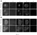
- FIG. 12 a is a process diagram of the cell state detection method
- FIG. 12 ,b shows the fluorescence microscopy image of M0 macrophages distinct into M1 state
- FIG. 12 ,c shows the fluorescence microscopy image of M0 macrophages distinct into M2 state
- FIG. 12 ,d compares the cell adhesion area of M0 macrophages, M1 state, and M2 state
- FIG. 12 ,e compares the cell roundness of M0 macrophages, M1 state, and M2 state
- FIG. 12 ,f compares the cellular traction force of M0 macrophages, M1 state, and M2 state.
- the present embodiment uses macrophages as detection subjects, places these cells on micro-/nano-pillars of different independent cellular traction force detection devices and uses lipopolysaccharides (LPS) and interleukin-4 (IL4) to guide macrophages from M0 to differentiate into M1 and M2 states, with M0 state serving as the control group.
- LPS lipopolysaccharides
- IL4 interleukin-4
- FIG.s 12 ,b and c are captured by the information acquisition unit (microscope used in the present embodiment), and further image processing and data analysis are performed using image/data processing devices (ImageJ and Python), transforming them into structured information and analyzing to produce the data for FIG.s 12 ,d-f.
- FIG.s 12 ,a to f Data from FIG.s 12 ,a to f indicate that there are significant differences between M0 macrophages and their distinct states of M1 and M2, both from direct observation ( FIG.s 12 ,b and c) and structured data quantification ( FIG.s 12 ,d-f).
- the present embodiment specifically provides a cellular identification system, as described in the twentieth embodiment, to obtain cellular traction force information and to analyze and detect cell states based on this information.
- the present embodiment offers methods for combining multicellular aggregates on the cellular traction force detection device in various ways, with two specific methods provided:
- the first method involves setting a culture medium on the micropillars of the cellular traction force detection device and transplanting cells into the culture medium on the micropillars to cultivate multicellular aggregates.
- this method allows for real-time monitoring of cell culture processes under visual representation of cellular traction force information, thereby being applicable for studying the effects of chemical, biological, and physical external stimuli such as culture media and drugs on cell growth.
- the second method involves directly attaching pre-cultivated multicellular aggregates to the micropillars of the cellular traction force detection device for detection.
- the present embodiment provides a method for culturing tumor cell aggregates on the cellular traction force detection device for drug sensitivity testing, including the following steps:
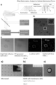
- FIG. 13 ,a-b wherein FIG. 13 ,a shows characterization images of tumor cell aggregates with/without the effect of 5-Fu in the first form, and FIG. 13 ,b for the second form. From left to right, these images include mixed images of cell membrane fluorescence and reflection signals 1, light reflection signals 2, nuclei 3, cell membranes 4, and cell force visualization images processed by optical image analysis software (Image J) 5. Due to cellular heterogeneity, tumor cells differ, and aggregates form in various shapes, leading to different attachment forms of cell aggregates.
- the present embodiment selects two representative forms for cell morphology detection: the first form represents larger cells adhered together, and the second form represents a cluster of smaller cells adhered together.
- FIG.s 13 ,a-b demonstrate that after treating cells with anti-tumor drugs to reduce their vitality, reflection signals significantly weaken; changes in cellular traction force before and after 5-Fu treatment indicate distinct drug sensitivities between the two forms of tumor cell aggregates.
- the cellular traction force detection device of the present application can measure the cellular traction force of multicellular aggregates (such as tumor aggregates), monitor the vitality state of cell aggregates, and distinguish different cell morphologies.
- multicellular aggregates refer to cell groups formed when cells, the basic structural and functional units of organisms, reproduce or differentiate to join together, including tumor aggregates obtained from in vitro or in vivo cultures.
Landscapes
- Engineering & Computer Science (AREA)
- Physics & Mathematics (AREA)
- Health & Medical Sciences (AREA)
- General Physics & Mathematics (AREA)
- Life Sciences & Earth Sciences (AREA)
- Chemical & Material Sciences (AREA)
- Theoretical Computer Science (AREA)
- General Health & Medical Sciences (AREA)
- Immunology (AREA)
- Pathology (AREA)
- Biochemistry (AREA)
- Analytical Chemistry (AREA)
- Software Systems (AREA)
- Biomedical Technology (AREA)
- Computing Systems (AREA)
- Artificial Intelligence (AREA)
- Evolutionary Computation (AREA)
- General Engineering & Computer Science (AREA)
- Mathematical Physics (AREA)
- Data Mining & Analysis (AREA)
- Molecular Biology (AREA)
- Dispersion Chemistry (AREA)
- Computer Vision & Pattern Recognition (AREA)
- Medical Informatics (AREA)
- Biophysics (AREA)
- Multimedia (AREA)
- Computational Linguistics (AREA)
- Signal Processing (AREA)
- Medicinal Chemistry (AREA)
- Food Science & Technology (AREA)
- Urology & Nephrology (AREA)
- Hematology (AREA)
- Databases & Information Systems (AREA)
- Optics & Photonics (AREA)
- Investigating Or Analysing Biological Materials (AREA)
- Image Analysis (AREA)
- Apparatus Associated With Microorganisms And Enzymes (AREA)
- Image Processing (AREA)
Applications Claiming Priority (2)
| Application Number | Priority Date | Filing Date | Title |
|---|---|---|---|
| CN202111127053.6A CN115880689A (zh) | 2021-09-26 | 2021-09-26 | 细胞识别的方法、装置和系统 |
| PCT/CN2022/121340 WO2023046167A1 (zh) | 2021-09-26 | 2022-09-26 | 一种细胞识别的方法、装置和系统 |
Publications (2)
| Publication Number | Publication Date |
|---|---|
| EP4407571A1 true EP4407571A1 (de) | 2024-07-31 |
| EP4407571A4 EP4407571A4 (de) | 2025-08-20 |
Family
ID=85720149
Family Applications (1)
| Application Number | Title | Priority Date | Filing Date |
|---|---|---|---|
| EP22872210.4A Pending EP4407571A4 (de) | 2021-09-26 | 2022-09-26 | Zellerkennungsverfahren, -vorrichtung und -system |
Country Status (6)
| Country | Link |
|---|---|
| US (1) | US20240418626A1 (de) |
| EP (1) | EP4407571A4 (de) |
| JP (1) | JP7730493B2 (de) |
| CN (2) | CN115880689A (de) |
| AU (1) | AU2022350581B2 (de) |
| WO (1) | WO2023046167A1 (de) |
Families Citing this family (1)
| Publication number | Priority date | Publication date | Assignee | Title |
|---|---|---|---|---|
| WO2024199142A1 (zh) * | 2023-03-24 | 2024-10-03 | 医工瑞新(厦门)科技有限公司 | 一种多模态生物物理表征装置、系统、方法及应用 |
Family Cites Families (8)
| Publication number | Priority date | Publication date | Assignee | Title |
|---|---|---|---|---|
| WO2011021391A1 (ja) * | 2009-08-19 | 2011-02-24 | 国立大学法人名古屋大学 | 培養細胞評価装置、インキュベータおよびプログラム |
| CN104359876B (zh) | 2014-10-14 | 2018-07-10 | 厦门大学 | 细胞牵引力显微镜及其在抗癌药物药效及药理检测中的应用 |
| CN106404915B (zh) * | 2016-08-29 | 2019-02-19 | 湖南农业大学 | 一种细胞牵引力的实时与定量测定方法 |
| US11782046B2 (en) * | 2017-07-03 | 2023-10-10 | The Regents Of The University Of California | Single-pixel optical technologies for instantly quantifying multicellular response profiles |
| CN110647874B (zh) * | 2019-11-28 | 2020-08-28 | 北京小蝇科技有限责任公司 | 一种端到端的血细胞识别模型构造方法及应用 |
| CN111666895B (zh) * | 2020-06-08 | 2023-05-26 | 上海市同济医院 | 基于深度学习的神经干细胞分化方向预测系统及方法 |
| CN111721451B (zh) * | 2020-06-19 | 2021-09-28 | 北京化工大学 | 基于图像的触觉传感方法、微型化装置及装置制备方法 |
| CN115876759A (zh) * | 2021-09-26 | 2023-03-31 | 瑞新(福州)科技有限公司 | 细胞机械力的检测系统、方法、装置及其制备方法 |
-
2021
- 2021-09-26 CN CN202111127053.6A patent/CN115880689A/zh active Pending
-
2022
- 2022-09-26 WO PCT/CN2022/121340 patent/WO2023046167A1/zh not_active Ceased
- 2022-09-26 EP EP22872210.4A patent/EP4407571A4/de active Pending
- 2022-09-26 AU AU2022350581A patent/AU2022350581B2/en active Active
- 2022-09-26 JP JP2024542229A patent/JP7730493B2/ja active Active
- 2022-09-26 CN CN202280064594.5A patent/CN118076981A/zh active Pending
-
2024
- 2024-03-22 US US18/614,516 patent/US20240418626A1/en active Pending
Also Published As
| Publication number | Publication date |
|---|---|
| US20240418626A1 (en) | 2024-12-19 |
| JP7730493B2 (ja) | 2025-08-28 |
| CN115880689A (zh) | 2023-03-31 |
| EP4407571A4 (de) | 2025-08-20 |
| CN118076981A (zh) | 2024-05-24 |
| AU2022350581A1 (en) | 2024-05-09 |
| AU2022350581B2 (en) | 2026-01-15 |
| WO2023046167A1 (zh) | 2023-03-30 |
| JP2024538845A (ja) | 2024-10-23 |
Similar Documents
| Publication | Publication Date | Title |
|---|---|---|
| Meijering et al. | Tracking in molecular bioimaging | |
| US10025271B2 (en) | Method and system for detecting and/or classifying cancerous cells in a cell sample | |
| Roy et al. | A review of recent progress in lens-free imaging and sensing | |
| de Siqueira e Oliveira et al. | Discrimination of selected species of pathogenic bacteria using near-infrared Raman spectroscopy and principal components analysis | |
| US20220383629A1 (en) | Label-free cell classification and screening system based on hybrid transfer learning | |
| EP4070232A1 (de) | Systeme und verfahren für hochdurchsatz-wirkstoffscreening | |
| CN112041660B (zh) | 用于移动粒子三维成像的系统、装置与方法 | |
| WO2009151610A2 (en) | Flow cytometer apparatus for three dimensional diffraction imaging and related methods | |
| CN101943663B (zh) | 自动辨别微粒的衍射图像测量分析系统及方法 | |
| Jang et al. | NeuroCa: integrated framework for systematic analysis of spatiotemporal neuronal activity patterns from large-scale optical recording data | |
| WO2019050847A1 (en) | RAPID DETECTION OF BACTERIA AND ANTIBIOTIC SENSITIVITY TESTING BY PRECISION MONITORING OF BACTERIAL CELLS | |
| Li et al. | An approach for cell viability online detection based on the characteristics of lensfree cell diffraction fingerprint | |
| US20240418626A1 (en) | Method, device, and system for cell identification | |
| US20240229097A1 (en) | System, method, device and manufacturing method thereof for detecting cellular mechanical force | |
| Hsieh et al. | Characterization and identification of cell death dynamics by quantitative phase imaging | |
| Yoon et al. | Label-free identification of lymphocyte subtypes using three-dimensional quantitative phase imaging and machine learning | |
| Chaudhari et al. | Cumulative learning based segmentation aided cell mixtures classification in digital holographic microscopy | |
| JP2020509347A (ja) | 細胞分析方法及び装置 | |
| Cheon et al. | Cellytics: A Digital Inline Holography Platform for Single Cell Analysis in Biomedical and Environmental Applications | |
| Naser et al. | Label-free dynamic segmentation and morphological analysis of subcellular optical scatterers | |
| EP4692300A1 (de) | Auf wirkstoffempfindlichkeit basierendes zellcharakterisierungs- und identifikationstypisierungssystem, verfahren und verwendung | |
| Xu et al. | Identification of lymphoma types using 2D light scattering microscopy and machine learning | |
| Polanco et al. | Determination of Drug Sensitivity in Patient Derived Models of Breast Cancer by Multiparametric QPI | |
| WO2018180012A1 (ja) | 情報処理装置、情報処理システム、及び情報処理方法 | |
| CN118685253A (zh) | 组织状态表征和识别系统、方法、应用 |
Legal Events
| Date | Code | Title | Description |
|---|---|---|---|
| STAA | Information on the status of an ep patent application or granted ep patent |
Free format text: STATUS: THE INTERNATIONAL PUBLICATION HAS BEEN MADE |
|
| PUAI | Public reference made under article 153(3) epc to a published international application that has entered the european phase |
Free format text: ORIGINAL CODE: 0009012 |
|
| STAA | Information on the status of an ep patent application or granted ep patent |
Free format text: STATUS: REQUEST FOR EXAMINATION WAS MADE |
|
| 17P | Request for examination filed |
Effective date: 20240423 |
|
| AK | Designated contracting states |
Kind code of ref document: A1 Designated state(s): AL AT BE BG CH CY CZ DE DK EE ES FI FR GB GR HR HU IE IS IT LI LT LU LV MC MK MT NL NO PL PT RO RS SE SI SK SM TR |
|
| DAV | Request for validation of the european patent (deleted) | ||
| DAX | Request for extension of the european patent (deleted) | ||
| STAA | Information on the status of an ep patent application or granted ep patent |
Free format text: STATUS: EXAMINATION IS IN PROGRESS |
|
| A4 | Supplementary search report drawn up and despatched |
Effective date: 20250721 |
|
| RIC1 | Information provided on ipc code assigned before grant |
Ipc: G06V 20/69 20220101AFI20250715BHEP Ipc: G01N 3/08 20060101ALI20250715BHEP Ipc: G01N 15/01 20240101ALI20250715BHEP Ipc: G01N 15/10 20240101ALI20250715BHEP Ipc: G01N 19/04 20060101ALI20250715BHEP Ipc: G01N 33/483 20060101ALI20250715BHEP Ipc: G01N 15/14 20240101ALN20250715BHEP |
|
| 17Q | First examination report despatched |
Effective date: 20250801 |