EP4407331A1 - Batteriepack und beurteilungsverfahren - Google Patents
Batteriepack und beurteilungsverfahren Download PDFInfo
- Publication number
- EP4407331A1 EP4407331A1 EP22872733.5A EP22872733A EP4407331A1 EP 4407331 A1 EP4407331 A1 EP 4407331A1 EP 22872733 A EP22872733 A EP 22872733A EP 4407331 A1 EP4407331 A1 EP 4407331A1
- Authority
- EP
- European Patent Office
- Prior art keywords
- section
- element section
- secondary batteries
- series
- battery pack
- Prior art date
- Legal status (The legal status is an assumption and is not a legal conclusion. Google has not performed a legal analysis and makes no representation as to the accuracy of the status listed.)
- Pending
Links
Images


Classifications
-
- H—ELECTRICITY
- H01—ELECTRIC ELEMENTS
- H01M—PROCESSES OR MEANS, e.g. BATTERIES, FOR THE DIRECT CONVERSION OF CHEMICAL ENERGY INTO ELECTRICAL ENERGY
- H01M10/00—Secondary cells; Manufacture thereof
- H01M10/42—Methods or arrangements for servicing or maintenance of secondary cells or secondary half-cells
- H01M10/48—Accumulators combined with arrangements for measuring, testing or indicating the condition of cells, e.g. the level or density of the electrolyte
-
- G—PHYSICS
- G01—MEASURING; TESTING
- G01R—MEASURING ELECTRIC VARIABLES; MEASURING MAGNETIC VARIABLES
- G01R31/00—Arrangements for testing electric properties; Arrangements for locating electric faults; Arrangements for electrical testing characterised by what is being tested not provided for elsewhere
- G01R31/36—Arrangements for testing, measuring or monitoring the electrical condition of accumulators or electric batteries, e.g. capacity or state of charge [SoC]
- G01R31/396—Acquisition or processing of data for testing or for monitoring individual cells or groups of cells within a battery
-
- G—PHYSICS
- G01—MEASURING; TESTING
- G01R—MEASURING ELECTRIC VARIABLES; MEASURING MAGNETIC VARIABLES
- G01R31/00—Arrangements for testing electric properties; Arrangements for locating electric faults; Arrangements for electrical testing characterised by what is being tested not provided for elsewhere
- G01R31/36—Arrangements for testing, measuring or monitoring the electrical condition of accumulators or electric batteries, e.g. capacity or state of charge [SoC]
- G01R31/389—Measuring internal impedance, internal conductance or related variables
-
- H—ELECTRICITY
- H01—ELECTRIC ELEMENTS
- H01M—PROCESSES OR MEANS, e.g. BATTERIES, FOR THE DIRECT CONVERSION OF CHEMICAL ENERGY INTO ELECTRICAL ENERGY
- H01M10/00—Secondary cells; Manufacture thereof
- H01M10/42—Methods or arrangements for servicing or maintenance of secondary cells or secondary half-cells
- H01M10/425—Structural combination with electronic components, e.g. electronic circuits integrated to the outside of the casing
- H01M10/4264—Structural combination with electronic components, e.g. electronic circuits integrated to the outside of the casing with capacitors
-
- H—ELECTRICITY
- H01—ELECTRIC ELEMENTS
- H01M—PROCESSES OR MEANS, e.g. BATTERIES, FOR THE DIRECT CONVERSION OF CHEMICAL ENERGY INTO ELECTRICAL ENERGY
- H01M10/00—Secondary cells; Manufacture thereof
- H01M10/42—Methods or arrangements for servicing or maintenance of secondary cells or secondary half-cells
- H01M10/48—Accumulators combined with arrangements for measuring, testing or indicating the condition of cells, e.g. the level or density of the electrolyte
- H01M10/482—Accumulators combined with arrangements for measuring, testing or indicating the condition of cells, e.g. the level or density of the electrolyte for several batteries or cells simultaneously or sequentially
-
- H—ELECTRICITY
- H01—ELECTRIC ELEMENTS
- H01M—PROCESSES OR MEANS, e.g. BATTERIES, FOR THE DIRECT CONVERSION OF CHEMICAL ENERGY INTO ELECTRICAL ENERGY
- H01M50/00—Constructional details or processes of manufacture of the non-active parts of electrochemical cells other than fuel cells, e.g. hybrid cells
- H01M50/50—Current conducting connections for cells or batteries
- H01M50/502—Interconnectors for connecting terminals of adjacent batteries; Interconnectors for connecting cells outside a battery casing
- H01M50/519—Interconnectors for connecting terminals of adjacent batteries; Interconnectors for connecting cells outside a battery casing comprising printed circuit boards [PCB]
-
- H—ELECTRICITY
- H02—GENERATION; CONVERSION OR DISTRIBUTION OF ELECTRIC POWER
- H02J—ELECTRIC POWER NETWORKS; CIRCUIT ARRANGEMENTS OR SYSTEMS FOR SUPPLYING OR DISTRIBUTING ELECTRIC POWER; SYSTEMS FOR STORING ELECTRIC ENERGY
- H02J7/00—Circuit arrangements for charging or discharging batteries or for supplying loads from batteries
- H02J7/50—Circuit arrangements for charging or discharging batteries or for supplying loads from batteries acting upon multiple batteries simultaneously or sequentially
- H02J7/575—Parallel/serial switching of connection of batteries to charge or load circuit
-
- H—ELECTRICITY
- H02—GENERATION; CONVERSION OR DISTRIBUTION OF ELECTRIC POWER
- H02J—ELECTRIC POWER NETWORKS; CIRCUIT ARRANGEMENTS OR SYSTEMS FOR SUPPLYING OR DISTRIBUTING ELECTRIC POWER; SYSTEMS FOR STORING ELECTRIC ENERGY
- H02J7/00—Circuit arrangements for charging or discharging batteries or for supplying loads from batteries
- H02J7/80—Circuit arrangements for charging or discharging batteries or for supplying loads from batteries including monitoring or indicating arrangements
- H02J7/84—Control of state of health [SOH]
-
- H—ELECTRICITY
- H02—GENERATION; CONVERSION OR DISTRIBUTION OF ELECTRIC POWER
- H02J—ELECTRIC POWER NETWORKS; CIRCUIT ARRANGEMENTS OR SYSTEMS FOR SUPPLYING OR DISTRIBUTING ELECTRIC POWER; SYSTEMS FOR STORING ELECTRIC ENERGY
- H02J2105/00—Networks for supplying or distributing electric power characterised by their spatial reach or by the load
- H02J2105/30—Networks for supplying or distributing electric power characterised by their spatial reach or by the load the load networks being external to vehicles, i.e. exchanging power with vehicles
- H02J2105/33—Networks for supplying or distributing electric power characterised by their spatial reach or by the load the load networks being external to vehicles, i.e. exchanging power with vehicles exchanging power with road vehicles
- H02J2105/37—Networks for supplying or distributing electric power characterised by their spatial reach or by the load the load networks being external to vehicles, i.e. exchanging power with vehicles exchanging power with road vehicles exchanging power with electric vehicles [EV] or with hybrid electric vehicles [HEV]
-
- Y—GENERAL TAGGING OF NEW TECHNOLOGICAL DEVELOPMENTS; GENERAL TAGGING OF CROSS-SECTIONAL TECHNOLOGIES SPANNING OVER SEVERAL SECTIONS OF THE IPC; TECHNICAL SUBJECTS COVERED BY FORMER USPC CROSS-REFERENCE ART COLLECTIONS [XRACs] AND DIGESTS
- Y02—TECHNOLOGIES OR APPLICATIONS FOR MITIGATION OR ADAPTATION AGAINST CLIMATE CHANGE
- Y02E—REDUCTION OF GREENHOUSE GAS [GHG] EMISSIONS, RELATED TO ENERGY GENERATION, TRANSMISSION OR DISTRIBUTION
- Y02E60/00—Enabling technologies; Technologies with a potential or indirect contribution to GHG emissions mitigation
- Y02E60/10—Energy storage using batteries
Definitions
- the present invention relates to a battery pack and an assessment method.
- Patent Literature 1 discloses an apparatus in which different label elements with different impedance characteristics are respectively added in parallel to a plurality of secondary batteries in order to apply different modulations to the impedance characteristics of the secondary batteries, in a battery pack composed of the plurality of secondary batteries connected in series.
- the method disclosed in PTL 1 limits an assumed internal configuration of the battery pack to a configuration in which the secondary batteries are connected in series, and the number of label elements that can be used simultaneously is limited.
- obtainable information is also limited to the impedance characteristic around the frequency assumed in the design stage of the label element. That is, it is difficult to determine the presence or absence of a secondary battery in a deteriorated state only by measuring a change in the impedance characteristic of the entire battery pack as in the conventional method, and it is difficult to understand the condition of each secondary battery.
- a battery pack according to the present invention includes a plurality of secondary batteries, and the battery pack is capable of assessing the plurality of secondary batteries and includes: an electrical circuit element section that is used in assessing the plurality of secondary batteries and is placed such that it is connectable to the plurality of secondary batteries; and a switching section that is connected to the electrical circuit element section and the plurality of secondary batteries and is configured to be capable of switching an impedance characteristic of the battery pack as a whole between use of the electrical circuit element section and non-use of the electrical circuit element section.
- An assessment method is for a battery pack including a plurality of secondary batteries, an electrical circuit element section that is used in assessing the plurality of secondary batteries and is placed such that it is connectable to the plurality of secondary batteries, and a switching section that is connected to the electrical circuit element section and the plurality of secondary batteries, and the method includes: switching an impedance characteristic of the battery pack as a whole between use of the electrical circuit element section and non-use of the electrical circuit element section; and assessing the plurality of secondary batteries.
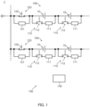
- FIG. 1 illustrates an exemplary configuration of a battery pack 1 according to the present invention.
- the battery pack 1 is, for example, a battery pack mounted on a vehicle such as an electric car and includes a plurality of secondary batteries 10 and an assessment section 100.
- the plurality of secondary batteries 10 are, for example, lithium-ion batteries, and supply power to a load (not illustrated) connected thereto. In addition, the plurality of secondary batteries 10 are supplied with power from an external power source at the time of charging.
- the plurality of secondary batteries 10 are connected in series or in parallel.
- n series groups 10A in which m secondary batteries 10 are connected in series are connected in parallel with each other.
- the m and n are any numbers greater than or equal to 2.
- the assessment section 100 is configured to be able to assess the plurality of secondary batteries 10, and includes first circuit sections 110, second circuit sections 120, and a control section 130.
- the plurality of first circuit sections 110 are provided corresponding to the plurality of secondary batteries 10 respectively, and each include a parallel element section 111 and a first switching section 112.
- the plurality of second circuit sections 120 are provided corresponding to the plurality of series groups 10A in the battery pack 1 respectively, and each include a series element section 121 and a second switching section 122.
- the series element section 121 is, for example, an electrical circuit element section such as a coil, and is connected in series with the plurality of secondary batteries 10 included in each series group 10A.
- the series element section 121 is not used when the power of the plurality of secondary batteries 10 can be inputted and outputted, and is used when the plurality of secondary batteries 10 are assessed.
- the series element sections 121 have the same electrical parameter.
- the electrical parameter is a generic term for a parameter that determines a characteristic of the element, such as capacitance, inductance, and resistance.
- the second switching section 122 is, for example, a switching circuit section such as a switching element and a relay element, and is placed in parallel with each series element section 121.
- the second switching section 122 is configured to be able to switch wires 1C (see FIG. 2B ), to which both ends of the second switching section 122 are connected, between a conductive state and a non-conductive state.
- the second switching section 122 is in the conductive state (see FIG. 1 and the two-dot-dash line of FIG. 2B ) when the series element section 121 is not used.
- the second switching section 122 is in the non-conductive state (see the solid line of FIG. 2B ) when the series element section 121 is used.
- the switching of the second switching section 122 between when the series element section 121 is used and not used in this manner causes a difference in the impedance characteristic between when the series element section 121 is used and not used. For example, the change in the impedance characteristics in one series group 10A and in one series element section 121 and one second switching section 122 is checked when the series element section 121 is used and not used.
- the impedance of the series group 10A portion is Zx
- the impedance of the series element section 121 portion is Zs.
- the admittance of the entire circuit portion including the secondary batteries 10 and the series element section 121 is 1/Zx.
- the admittance of the entire circuit portion including the series group 10A and the series element section 121 is 1/(Zx + Zs).
- ⁇ Y which is a difference in the admittance between when the series element section 121 is used and not used, is 1/Zx - 1/(Zx + Zs).
- Zx can be calculated from this ⁇ Y and the above Zs.
- the present embodiment it is possible to cause a difference in the impedance (admittance) characteristic of the entire battery pack 1 by switching the second switching section 122 between when the series element section 121 is used and not used.
- separately switching each of the plurality of second switching sections 122 makes it easier to determine whether the secondary batteries 10 included in which series group 10A are deteriorated.
- the electrical parameter of the series element section 121 can be set to any value according to an assumed noise amount or the like. A larger value of the above ⁇ Y regarding the series element section 121 is better from the viewpoint of accuracy improvement, and thus it is preferable that Zs is as large as possible for the electrical parameter of the series element section 121.
- the parallel element section 111 is, for example, an electrical circuit element section such as a capacitor, and is placed in parallel with the secondary battery 10.
- a plurality of the parallel element sections 111 are provided corresponding to the plurality of secondary batteries 10 respectively, not used when the power of the plurality of secondary batteries 10 can be inputted and outputted, and used when the plurality of secondary batteries 10 are assessed.
- the parallel element sections 111 each have the same electrical parameter.
- the first switching section 112 is, for example, a switching circuit section such as a switching element and a relay element, and is connected in series with each parallel element section 111.
- the first switching section 112 is configured to be able to switch the parallel element section 111 and the secondary battery 10 between a connected state and a disconnected state.
- a case where the parallel element section 111 and the secondary battery 10 are in the connected state corresponds to a case where a wire 1A to which one end of the first switching section 112 is connected and a wire 1B to which the other end is connected are in the conductive state (see the solid line in FIG. 2A ).
- a case where the parallel element section 111 and the secondary battery 10 are in the disconnected state corresponds to a case where the wire 1A to which one end of the first switching section 112 is connected and the wire 1B to which the other end is connected are in the non-conductive state (see FIG. 1 and the two-dot-dash line of FIG. 2A ).
- the first switching section 112 sets the parallel element section 111 and the secondary battery 10 in the disconnected state (see the two-dot-dash line of FIG. 2A ).
- the first switching section 112 sets the parallel element section 111 and the plurality of secondary batteries 10 in the connected state (see the solid line of FIG. 2A ).
- Switching the first switching section 112 between when the parallel element section 111 is used and not used in this manner causes a difference in the impedance characteristic between when the parallel element section 111 is used and not used. For example, the change in the impedance characteristics in one secondary battery 10 and in one parallel element section 111 and one first switching section 112 is checked when the parallel element section 111 is used and not used.
- the impedance of the secondary battery 10 portion is Zx
- the impedance of the parallel element section 111 portion is Zp.
- the impedance of the entire series group 10A including the secondary battery 10 and the parallel element section 111 is Zx.
- the impedance of the entire series group 10A including the secondary battery 10 and the parallel element section 111 is Zx ⁇ Zp/(Zx + Zp).
- ⁇ Z which is a difference between when the secondary battery 10 is used and assessed, is Zx - Zx ⁇ Zp/(Zx + Zp).
- Zx can be calculated from this ⁇ Z and the above Zp.
- the electrical parameter of the parallel element section 111 can be set to any value according to an assumed noise amount or the like. A larger value of the above ⁇ Z regarding the parallel element section 111 is better from the viewpoint of accuracy improvement, and thus it is preferable that Zp is as small as possible for the electrical parameter of the parallel element section 111.
- the impedance of the secondary battery 10 is calculated by switching each of the first switching section 112 and the second switching section 122. For example, in order to calculate the impedance of a particular secondary battery 10, the impedance of the entire battery pack 1 is measured under four conditions of the first measurement, the second measurement, the third measurement, and the fourth measurement.
- the condition of the first measurement is a condition in which all first switching sections 112 are in the non-conductive state (the parallel element sections 111 are in the disconnected state) and all second switching sections 122 are in the conductive state. This is the same condition as when the battery pack 1 supplies power and is supplied with power.
- the condition of the second measurement is a condition in which all first switching sections 112 are in the non-conductive state, the second switching section 122 corresponding to the series group 10A including the particular secondary battery 10 is in the non-conductive state, and the second switching sections 122 corresponding to the other series groups 10A are in the conductive state.
- the condition of the third measurement is a condition in which the first switching section 112 corresponding to the particular secondary battery 10 is in the conductive state (the parallel element section 111 is in the connected state), the other first switching sections 112 are in the non-conductive state, and all second switching sections 122 are in the conductive state.
- the condition of the fourth measurement is a condition in which the first switching section 112 corresponding to the particular secondary battery 10 is in the conductive state, the other first switching sections 112 are in the non-conductive state, the second switching section 122 corresponding to the series group 10A including the particular secondary battery 10 is in the non-conductive state, and the second switching sections 122 corresponding to the other series groups 10A are in the conductive state.
- the impedance of the particular secondary battery 10 can be measured based on the impedance of the entire battery pack 1 measured under the above four conditions. Note that the above conditions are examples, and any condition may be used as long as the impedance of the secondary battery 10 can be measured.
- the control section 130 is, for example, an electronic control section (ECU) mounted on a vehicle, and includes a central processing unit (CPU), read only memory (ROM), random access memory (RAM), and input/output circuitry that are not illustrated.
- the control section 130 performs control to switch the first switching section 112 and the second switching section 122 between when the electrical circuit element section is used and not used, based on a preset program.
- the first switching section 112 and the second switching section 122 may be switched by, for example, a manual operation of a user.
- a measurement device is connected to the battery pack 1, and the secondary battery 10 in a deteriorated state is determined by user's visual inspection etc.
- the control section 130 may perform control to switch the first switching section 112 and the second switching section 122 by combining the first measurement, the second measurement, the third measurement, and the fourth measurement described above, to finally measure the impedances of the secondary batteries 10 composing the entire battery pack 1.
- control section 130 may perform control to notify a user of an assessment result of the battery pack 1.
- assessment result of the battery pack information such as the presence or absence of the secondary battery 10 in the deteriorated state and which secondary battery 10 is in the deteriorated state is obtained.
- the notification of the assessment result may be in any way as long as a user can receive the notification, such as displaying information related to the assessment result on a display device and outputting the information by voice or the like.
- FIG. 3 is a flowchart describing the exemplary assessment method for the battery pack 1 in the assessment section 100.
- control section 130 switches the state of each second switching section 122 to assess each series group 10A in the battery pack 1 (step S101).
- step S101 for example, it is assumed that a deteriorated series group 10A is present when the difference in the impedance in each series group 10A measured by the above first measurement and second measurement is large.
- control section 130 switches the state of each first switching section 112 and assesses each of secondary batteries 10 of that series group 10A (step S102).
- each of the secondary batteries 10 is assessed by performing the above first measurement, second measurement, third measurement, and fourth measurement on each of the secondary batteries 10 of the deteriorated series group 10A, for example.
- control section 130 specifies a deteriorated secondary battery 10 and performs processing for notifying a user (step S103). This control is terminated after step S103.
- the impedance characteristic of the entire battery pack 1 is switched between when the electrical circuit element section is used and not used.
- the impedance characteristic of the entire battery pack 1 is switched by using the parallel element section 111 and the series element section 121 together. That is, the impedances of the respective series groups 10A can be calculated by separately switching the second switching sections 122 corresponding to the series element sections 121. To be more specific, by switching the second switching sections 122, the impedances of the respective series groups 10A can be individually calculated from the impedance of the entire series groups 10A (the secondary batteries 10, in the case of FIG. 5 described later) connected in parallel with each other. That is, the sum of admittances of the series groups 10A connected in parallel with each other can be broken down into the admittances of the respective series groups 10A, which are the components.
- the impedances of the respective secondary batteries 10 in the series group 10A can be calculated.
- the impedance of each of the secondary batteries 10 can be calculated even in a configuration including a plurality of secondary batteries 10 for which a series connection and a parallel connection are combined, thereby improving the assessment efficiency.
- the plurality of parallel element sections 111 or the plurality of series element sections 121 have the same electrical parameter, it is possible to easily calculate the impedance as compared with a configuration with different electrical parameters.
- first switching section 112 is connected to one parallel element section 111 in the above embodiment, the present invention is not limited to this.
- the first switching section 112 may be configured to be connected to either one of two parallel element sections 111A and 111B as illustrated in FIG. 4A .
- the first circuit section 110 includes a first parallel element section 111A, a second parallel element section 111B, and the first switching section 112.
- the first parallel element section 111A and the second parallel element section 111B have different electrical parameters.
- the first switching section 112 is connected to the first parallel element section 111A when the first parallel element section 111A is used and the second parallel element section 111B is not used, and is connected to the second parallel element section 111B when the first parallel element section 111A is not used and the second parallel element section 111B is used. Note that, in this configuration, a parallel element section connected (used) at the time of the assessment of the battery pack 1 may be determined freely.
- the electrical parameter of the parallel element section can be different between when used and not used.
- the impedance characteristic of the entire battery pack 1 can also be switched in this manner between when each parallel element section is used and not used; accordingly, the impedance of each of the secondary batteries 10 can be calculated, and the states of the plurality of secondary batteries can be easily understood.
- the second switching section 122 is connected to one series element section 121 in the above embodiment, the present invention is not limited to this.
- the second switching section 122 may be configured to be connected to one of two series element sections 121A and 121B as illustrated in FIG. 4B .
- the second circuit section 120 includes a first series element section 121A, a second series element section 121B, and the second switching section 122.
- the first series element section 121A and the second series element section 121B have different electrical parameters.
- the second switching section 122 is connected to the first series element section 121Awhen the first series element section 121Ais used and the second series element section 121B is not used, and is connected to the second series element section 121B when the first series element section 121A is not used and the second series element section 121B is used. Note that, in this configuration, a series element section connected (used) at the time of the assessment of the battery pack 1 may be determined freely.
- the electrical parameter of the series element section can be different between when used and not used.
- the impedance characteristic can also be switched in this manner between when each series element section is used and not used; accordingly, the impedance of each of the series groups 10A can be calculated, and the states of the plurality of secondary batteries can be easily understood.
- switching section is connected to any one of the electrical circuit element sections in the configurations illustrated in FIG. 4A and FIG. 4B , non-ideality of the switching section (variation in on-resistance and off-resistance) can be cancelled by any one of the electrical circuit element sections.
- the electrical parameter of the element section can be adjusted by providing two (a plurality of) parallel element sections or series element sections having different electrical parameters, but the present invention is not limited to this.
- the parallel element section or the series element section may be a variable element (variable resistance, variable capacitor, etc.), so that the parallel element section or the series element section is configured to be able to adjust the electrical parameter.
- the switching section in this case is, for example, an operation section or the like that can adjust the electrical parameter of the variable element.
- the battery pack 1 is configured to include a group of secondary batteries connected in series, but the present invention is not limited to this.
- the battery pack 1 may be configured to include a parallel group 10B of the secondary batteries 10 connected in parallel.
- one first circuit section 110 is provided to each parallel group 10B, and the second circuit section 120 is provided corresponding to each of the plurality of secondary batteries 10 in each parallel group 10B.
- the parallel element section 111 is connected in parallel with each parallel group 10B.
- the first switching section 112 is connected in series with the parallel element section 111 and is connected in parallel with each parallel group 10B.
- the series element section 121 is connected in series with each secondary battery 10.
- the second switching section 122 is connected in parallel with the series element section 121 and is connected in series with the secondary battery 10.
- the first switching section 112 sets the parallel element section 111 and the parallel group 10B to the disconnected state when the parallel element section 111 is not used, and sets the parallel element section 111 and the parallel group 10B to the connected state when the parallel element section 111 is used.
- the second switching section 122 is brought into the conductive state when the series element section 121 is not used, and is brought into the non-conductive state when the series element section 121 is used.
- the impedance characteristic of the parallel group 10B can be calculated from the impedance characteristic of the entire battery pack by using the first circuit section 110. Further, the impedance of each of the secondary batteries 10 can be calculated from the impedance of the parallel group 10B by using the second circuit section 120. As a result, the states of the plurality of secondary batteries 10 can also be easily understood in such a configuration.
- the parallel element section 111 is provided corresponding to one secondary battery 10 in the above embodiment, the present invention is not limited to this.
- the present invention may be provided corresponding to two or more secondary batteries 10 connected in series.
- one parallel element section 111 is connected in parallel with two secondary batteries 10.
- the states of the plurality of secondary batteries can also be easily understood in such a configuration. Further, since the parallel element section 111 is provided corresponding to two or more secondary batteries 10, the number of parallel element sections 111 can be reduced.
- a single secondary battery 10 is connected to two parallel element sections 111 in an overlapping manner.
- one end of the single secondary battery 10 is connected to a third parallel element section 111C, and the other end of the secondary battery 10 is connected to a fourth parallel element section 111D.
- the other end of the secondary battery 10 is connected to the fourth parallel element section 111D via the first switching section 112 connected to the fourth parallel element section 111D.
- the deteriorated secondary battery 10 can be accurately specified in the configuration illustrated in FIG. 6B .
- the parallel element section 111 is configured to have only a capacitor, but the present invention is not limited to this, and other electrical circuit elements may be configured to be included in addition to the capacitor.
- the series element section 121 is configured to have only a coil, but the present invention is not limited to this, and the series element section 121 may be configured to have only a resistance element, or may be configured to include other electrical circuit elements in addition to the coil or the resistance element.
- the resistance value is 0, and it is thus possible to perform the assessment measurement while charging and discharging the battery pack.
- the resistance element may have infinite resistance.
- the series element section may be configured to be in an open circuit state, and the above assessment method is valid by considering that the impedance of the series element section is infinite. When the resistance element has infinite resistance, there is no difference between the second measurement and the fourth measurement described above, thereby reducing the number of times of measurement as a whole.
- the plurality of parallel element sections 111 have the same electrical parameter, but the present invention is not limited to this, and they may have different electrical parameters.
- the plurality of series element sections 121 have the same electrical parameter, but the present invention is not limited to this, and they may have different electrical parameters.
- the parallel element section 111 and the series element section 121 are used in combination, that is, the series-connected secondary battery and the parallel-connected secondary battery are combined, but the present invention is not limited to this.
- only one of the parallel element section and the series element section, that is, only the parallel-connected secondary battery or only the series-connected secondary battery may be configured to be provided, or the configuration may correspond to all possible combinations of the series-connected secondary battery and the parallel-connected secondary battery.
- control section 130 is an ECU in the above embodiment, the present invention is not limited to this, and it may be an external device.
- the external device include a device installed in a vehicle and capable of measuring the impedance characteristic while in use or inactive, a device installed in a vehicle charging facility and capable of measuring the impedance characteristic during charging, and an independent measurement device for measuring the impedance characteristic in a repair shop or a recycling facility.
- the assessment method based on the flowchart illustrated in FIG. 3 is used, but the present invention is not limited to this, and another method such as a method of calculating the impedances of all the secondary batteries 10 may be used.
- a battery pack of the present invention is useful for a battery pack and an assessment method each capable of understanding the conditions of a plurality of secondary batteries easily.
Landscapes
- Engineering & Computer Science (AREA)
- Chemical & Material Sciences (AREA)
- Chemical Kinetics & Catalysis (AREA)
- Electrochemistry (AREA)
- General Chemical & Material Sciences (AREA)
- Manufacturing & Machinery (AREA)
- Physics & Mathematics (AREA)
- General Physics & Mathematics (AREA)
- Power Engineering (AREA)
- Microelectronics & Electronic Packaging (AREA)
- Secondary Cells (AREA)
Applications Claiming Priority (2)
| Application Number | Priority Date | Filing Date | Title |
|---|---|---|---|
| JP2021155462 | 2021-09-24 | ||
| PCT/JP2022/033852 WO2023047978A1 (ja) | 2021-09-24 | 2022-09-09 | 組電池および評価方法 |
Publications (2)
| Publication Number | Publication Date |
|---|---|
| EP4407331A1 true EP4407331A1 (de) | 2024-07-31 |
| EP4407331A4 EP4407331A4 (de) | 2025-10-15 |
Family
ID=85720599
Family Applications (1)
| Application Number | Title | Priority Date | Filing Date |
|---|---|---|---|
| EP22872733.5A Pending EP4407331A4 (de) | 2021-09-24 | 2022-09-09 | Batteriepack und beurteilungsverfahren |
Country Status (5)
| Country | Link |
|---|---|
| US (1) | US12601792B2 (de) |
| EP (1) | EP4407331A4 (de) |
| JP (1) | JP7687726B2 (de) |
| CN (1) | CN117980756A (de) |
| WO (1) | WO2023047978A1 (de) |
Family Cites Families (15)
| Publication number | Priority date | Publication date | Assignee | Title |
|---|---|---|---|---|
| KR20130142409A (ko) | 2012-06-19 | 2013-12-30 | 삼성에스디아이 주식회사 | 배터리 팩 및 이의 제어방법 |
| FR3004855B1 (fr) * | 2013-04-22 | 2015-04-24 | Commissariat Energie Atomique | Systeme de batterie de puissance pour la determination de l'impedance d'un etage |
| DE102013218081A1 (de) | 2013-09-10 | 2015-03-12 | Robert Bosch Gmbh | Batteriemoduleinrichtung und Verfahren zur Bestimmung einer komplexen Impedanz eines in einer Batteriemoduleinrichtung angeordneten Batteriemoduls |
| JP6209173B2 (ja) * | 2015-02-26 | 2017-10-04 | 東洋ゴム工業株式会社 | 密閉型二次電池の劣化診断方法及び劣化診断システム |
| JP6679342B2 (ja) * | 2016-02-24 | 2020-04-15 | Ntn株式会社 | 二次電池の劣化判定装置 |
| EP3333008B1 (de) * | 2016-12-12 | 2022-06-15 | Honeywell International Inc. | Adaptives ausgleichen zur batterieverwaltung |
| US10670639B2 (en) * | 2017-02-21 | 2020-06-02 | Canon Kabushiki Kaisha | Apparatus for detecting alternating current zero cross and voltage |
| JP6561407B2 (ja) | 2017-04-07 | 2019-08-21 | 学校法人早稲田大学 | 組電池、電池モジュールおよび電池モジュールの評価方法 |
| JP2021155462A (ja) | 2018-06-29 | 2021-10-07 | Jnc株式会社 | シロキサンポリマー架橋硬化物 |
| US11018384B2 (en) | 2018-07-27 | 2021-05-25 | Nxp B.V. | Dual-cell supervisor circuit for high-voltage automotive battery packs |
| JP6477964B1 (ja) * | 2018-09-13 | 2019-03-06 | ミツミ電機株式会社 | 二次電池保護回路 |
| JP7172838B2 (ja) | 2019-04-26 | 2022-11-16 | 株式会社デンソー | 電池監視装置 |
| US11362536B2 (en) | 2019-06-27 | 2022-06-14 | Motorola Solutions, Inc. | Methods and apparatus for detecting open circuit faults in a battery pack containing parallel cells |
| JP2022056756A (ja) * | 2020-09-30 | 2022-04-11 | Tdk株式会社 | 電流検出回路、電力変換装置および電力システム |
| US20240142534A1 (en) * | 2022-10-28 | 2024-05-02 | Volvo Car Corporation | Intelligent battery system |
-
2022
- 2022-09-09 WO PCT/JP2022/033852 patent/WO2023047978A1/ja not_active Ceased
- 2022-09-09 JP JP2023549473A patent/JP7687726B2/ja active Active
- 2022-09-09 EP EP22872733.5A patent/EP4407331A4/de active Pending
- 2022-09-09 CN CN202280063933.8A patent/CN117980756A/zh active Pending
- 2022-09-09 US US18/694,080 patent/US12601792B2/en active Active
Also Published As
| Publication number | Publication date |
|---|---|
| JPWO2023047978A1 (de) | 2023-03-30 |
| EP4407331A4 (de) | 2025-10-15 |
| CN117980756A (zh) | 2024-05-03 |
| US12601792B2 (en) | 2026-04-14 |
| US20240385257A1 (en) | 2024-11-21 |
| JP7687726B2 (ja) | 2025-06-03 |
| WO2023047978A1 (ja) | 2023-03-30 |
Similar Documents
| Publication | Publication Date | Title |
|---|---|---|
| US10429449B2 (en) | Battery pack tester | |
| US9291681B2 (en) | Monitoring apparatus and method of battery contact point in charge/discharge system with batteries connected in series | |
| JP5728343B2 (ja) | 変圧器の健全性診断方法及び健全性診断装置 | |
| JP6365431B2 (ja) | 充放電試験装置の校正方法 | |
| US9132733B2 (en) | Insulation failure diagnosis apparatus and method of diagnosing insulation failure | |
| US20220050142A1 (en) | High capacity battery balancer | |
| US20150168478A1 (en) | Method and apparatus for measuring load tap changer characteristics | |
| US11067635B2 (en) | Battery cell evaluation system | |
| US8427182B2 (en) | Test apparatus and power supply apparatus | |
| KR20150005953A (ko) | 절연 검사 방법 및 절연 검사 장치 | |
| EP4407331A1 (de) | Batteriepack und beurteilungsverfahren | |
| JP6337836B2 (ja) | 充放電試験装置の校正方法 | |
| RU2534387C1 (ru) | Способ автоматизированного контроля электрических цепей сложных технических изделий и устройство для реализации этого способа | |
| EP2506024B1 (de) | Batterietestgerät für Kaltstartstromtest | |
| JP2012220344A (ja) | セル電圧測定装置 | |
| EP3729576A2 (de) | Automatische mehrkanalige elektronische test- und messvorrichtung | |
| KR102764452B1 (ko) | 고전압 정션블록 테스트 장치 및 그 방법 | |
| JP5608935B2 (ja) | 高精度テスター | |
| JP7826019B2 (ja) | 検査装置、電池監視装置の検査方法 | |
| CN210465619U (zh) | 直流高电压高分断测试装置 | |
| JP2011059124A (ja) | 試験装置および電源装置 | |
| WO2025197306A1 (ja) | 検査システム | |
| JP2009198522A (ja) | 絶縁検査装置 | |
| JP5367045B2 (ja) | 制御回路点検装置及び制御回路点検方法 | |
| JPH06148299A (ja) | 電子部品測定装置 |
Legal Events
| Date | Code | Title | Description |
|---|---|---|---|
| STAA | Information on the status of an ep patent application or granted ep patent |
Free format text: STATUS: THE INTERNATIONAL PUBLICATION HAS BEEN MADE |
|
| PUAI | Public reference made under article 153(3) epc to a published international application that has entered the european phase |
Free format text: ORIGINAL CODE: 0009012 |
|
| STAA | Information on the status of an ep patent application or granted ep patent |
Free format text: STATUS: REQUEST FOR EXAMINATION WAS MADE |
|
| 17P | Request for examination filed |
Effective date: 20240321 |
|
| AK | Designated contracting states |
Kind code of ref document: A1 Designated state(s): AL AT BE BG CH CY CZ DE DK EE ES FI FR GB GR HR HU IE IS IT LI LT LU LV MC MK MT NL NO PL PT RO RS SE SI SK SM TR |
|
| DAV | Request for validation of the european patent (deleted) | ||
| DAX | Request for extension of the european patent (deleted) | ||
| A4 | Supplementary search report drawn up and despatched |
Effective date: 20250916 |
|
| RIC1 | Information provided on ipc code assigned before grant |
Ipc: G01R 31/389 20190101AFI20250910BHEP Ipc: G01R 31/396 20190101ALI20250910BHEP Ipc: H01M 10/48 20060101ALI20250910BHEP Ipc: H02J 7/00 20060101ALI20250910BHEP |