EP4407320A1 - Mikrofluidisches detektionssystem für einen kühlschrank und kühlschrank - Google Patents
Mikrofluidisches detektionssystem für einen kühlschrank und kühlschrank Download PDFInfo
- Publication number
- EP4407320A1 EP4407320A1 EP22871499.4A EP22871499A EP4407320A1 EP 4407320 A1 EP4407320 A1 EP 4407320A1 EP 22871499 A EP22871499 A EP 22871499A EP 4407320 A1 EP4407320 A1 EP 4407320A1
- Authority
- EP
- European Patent Office
- Prior art keywords
- sample
- sample cup
- bracket
- microfluidic
- detection system
- Prior art date
- Legal status (The legal status is an assumption and is not a legal conclusion. Google has not performed a legal analysis and makes no representation as to the accuracy of the status listed.)
- Pending
Links
- 238000001514 detection method Methods 0.000 title claims abstract description 152
- 239000000523 sample Substances 0.000 claims abstract description 222
- 238000000018 DNA microarray Methods 0.000 claims abstract description 79
- 238000005303 weighing Methods 0.000 claims abstract description 63
- 230000007246 mechanism Effects 0.000 claims abstract description 50
- 239000007788 liquid Substances 0.000 claims abstract description 44
- 239000007853 buffer solution Substances 0.000 claims abstract description 34
- 239000012488 sample solution Substances 0.000 claims abstract description 3
- 238000007789 sealing Methods 0.000 claims description 35
- 238000003825 pressing Methods 0.000 claims description 8
- 238000004891 communication Methods 0.000 claims description 7
- 230000000694 effects Effects 0.000 claims description 5
- 230000001960 triggered effect Effects 0.000 claims description 3
- 238000000034 method Methods 0.000 description 15
- 230000008569 process Effects 0.000 description 14
- 238000010586 diagram Methods 0.000 description 10
- 239000000575 pesticide Substances 0.000 description 10
- 238000006243 chemical reaction Methods 0.000 description 8
- 239000003153 chemical reaction reagent Substances 0.000 description 8
- 238000009434 installation Methods 0.000 description 8
- 230000009471 action Effects 0.000 description 7
- 238000013461 design Methods 0.000 description 7
- 238000013459 approach Methods 0.000 description 6
- 235000016709 nutrition Nutrition 0.000 description 6
- 239000012530 fluid Substances 0.000 description 5
- 238000005259 measurement Methods 0.000 description 5
- 230000010355 oscillation Effects 0.000 description 5
- 102000004190 Enzymes Human genes 0.000 description 4
- 108090000790 Enzymes Proteins 0.000 description 4
- 241000700605 Viruses Species 0.000 description 4
- 235000012041 food component Nutrition 0.000 description 4
- 239000005417 food ingredient Substances 0.000 description 4
- 239000000447 pesticide residue Substances 0.000 description 4
- 230000006378 damage Effects 0.000 description 3
- 238000005516 engineering process Methods 0.000 description 3
- 238000005057 refrigeration Methods 0.000 description 3
- 239000000126 substance Substances 0.000 description 3
- 238000009825 accumulation Methods 0.000 description 2
- 239000003795 chemical substances by application Substances 0.000 description 2
- 230000008878 coupling Effects 0.000 description 2
- 238000010168 coupling process Methods 0.000 description 2
- 238000005859 coupling reaction Methods 0.000 description 2
- 230000002708 enhancing effect Effects 0.000 description 2
- 238000012986 modification Methods 0.000 description 2
- 230000004048 modification Effects 0.000 description 2
- 238000005070 sampling Methods 0.000 description 2
- 239000000243 solution Substances 0.000 description 2
- 230000001360 synchronised effect Effects 0.000 description 2
- 230000007423 decrease Effects 0.000 description 1
- 230000007812 deficiency Effects 0.000 description 1
- 238000011161 development Methods 0.000 description 1
- 239000003814 drug Substances 0.000 description 1
- 229940079593 drug Drugs 0.000 description 1
- 235000013399 edible fruits Nutrition 0.000 description 1
- 230000005489 elastic deformation Effects 0.000 description 1
- 235000013305 food Nutrition 0.000 description 1
- 230000037406 food intake Effects 0.000 description 1
- 230000008014 freezing Effects 0.000 description 1
- 238000007710 freezing Methods 0.000 description 1
- 230000036541 health Effects 0.000 description 1
- 238000010438 heat treatment Methods 0.000 description 1
- 210000004251 human milk Anatomy 0.000 description 1
- 235000020256 human milk Nutrition 0.000 description 1
- 230000006872 improvement Effects 0.000 description 1
- 230000005764 inhibitory process Effects 0.000 description 1
- 238000012966 insertion method Methods 0.000 description 1
- 238000011900 installation process Methods 0.000 description 1
- 238000000520 microinjection Methods 0.000 description 1
- 235000013336 milk Nutrition 0.000 description 1
- 239000008267 milk Substances 0.000 description 1
- 210000004080 milk Anatomy 0.000 description 1
- 239000000203 mixture Substances 0.000 description 1
- 230000000474 nursing effect Effects 0.000 description 1
- 230000002572 peristaltic effect Effects 0.000 description 1
- 230000002035 prolonged effect Effects 0.000 description 1
- 238000011084 recovery Methods 0.000 description 1
- 230000000284 resting effect Effects 0.000 description 1
- 238000001356 surgical procedure Methods 0.000 description 1
- 235000013311 vegetables Nutrition 0.000 description 1
Images


Classifications
-
- B—PERFORMING OPERATIONS; TRANSPORTING
- B01—PHYSICAL OR CHEMICAL PROCESSES OR APPARATUS IN GENERAL
- B01L—CHEMICAL OR PHYSICAL LABORATORY APPARATUS FOR GENERAL USE
- B01L3/00—Containers or dishes for laboratory use, e.g. laboratory glassware; Droppers
- B01L3/50—Containers for the purpose of retaining a material to be analysed, e.g. test tubes
- B01L3/502—Containers for the purpose of retaining a material to be analysed, e.g. test tubes with fluid transport, e.g. in multi-compartment structures
- B01L3/5027—Containers for the purpose of retaining a material to be analysed, e.g. test tubes with fluid transport, e.g. in multi-compartment structures by integrated microfluidic structures, i.e. dimensions of channels and chambers are such that surface tension forces are important, e.g. lab-on-a-chip
- B01L3/502715—Containers for the purpose of retaining a material to be analysed, e.g. test tubes with fluid transport, e.g. in multi-compartment structures by integrated microfluidic structures, i.e. dimensions of channels and chambers are such that surface tension forces are important, e.g. lab-on-a-chip characterised by interfacing components, e.g. fluidic, electrical, optical or mechanical interfaces
-
- G—PHYSICS
- G01—MEASURING; TESTING
- G01N—INVESTIGATING OR ANALYSING MATERIALS BY DETERMINING THEIR CHEMICAL OR PHYSICAL PROPERTIES
- G01N33/00—Investigating or analysing materials by specific methods not covered by groups G01N1/00 - G01N31/00
- G01N33/48—Biological material, e.g. blood, urine; Haemocytometers
- G01N33/50—Chemical analysis of biological material, e.g. blood, urine; Testing involving biospecific ligand binding methods; Immunological testing
-
- B—PERFORMING OPERATIONS; TRANSPORTING
- B01—PHYSICAL OR CHEMICAL PROCESSES OR APPARATUS IN GENERAL
- B01L—CHEMICAL OR PHYSICAL LABORATORY APPARATUS FOR GENERAL USE
- B01L3/00—Containers or dishes for laboratory use, e.g. laboratory glassware; Droppers
-
- B—PERFORMING OPERATIONS; TRANSPORTING
- B01—PHYSICAL OR CHEMICAL PROCESSES OR APPARATUS IN GENERAL
- B01L—CHEMICAL OR PHYSICAL LABORATORY APPARATUS FOR GENERAL USE
- B01L3/00—Containers or dishes for laboratory use, e.g. laboratory glassware; Droppers
- B01L3/50—Containers for the purpose of retaining a material to be analysed, e.g. test tubes
- B01L3/502—Containers for the purpose of retaining a material to be analysed, e.g. test tubes with fluid transport, e.g. in multi-compartment structures
-
- F—MECHANICAL ENGINEERING; LIGHTING; HEATING; WEAPONS; BLASTING
- F25—REFRIGERATION OR COOLING; COMBINED HEATING AND REFRIGERATION SYSTEMS; HEAT PUMP SYSTEMS; MANUFACTURE OR STORAGE OF ICE; LIQUEFACTION SOLIDIFICATION OF GASES
- F25D—REFRIGERATORS; COLD ROOMS; ICE-BOXES; COOLING OR FREEZING APPARATUS NOT OTHERWISE PROVIDED FOR
- F25D23/00—General constructional features
- F25D23/02—Doors; Covers
- F25D23/028—Details
-
- F—MECHANICAL ENGINEERING; LIGHTING; HEATING; WEAPONS; BLASTING
- F25—REFRIGERATION OR COOLING; COMBINED HEATING AND REFRIGERATION SYSTEMS; HEAT PUMP SYSTEMS; MANUFACTURE OR STORAGE OF ICE; LIQUEFACTION SOLIDIFICATION OF GASES
- F25D—REFRIGERATORS; COLD ROOMS; ICE-BOXES; COOLING OR FREEZING APPARATUS NOT OTHERWISE PROVIDED FOR
- F25D23/00—General constructional features
- F25D23/12—Arrangements of compartments additional to cooling compartments; Combinations of refrigerators with other equipment, e.g. stove
-
- F—MECHANICAL ENGINEERING; LIGHTING; HEATING; WEAPONS; BLASTING
- F25—REFRIGERATION OR COOLING; COMBINED HEATING AND REFRIGERATION SYSTEMS; HEAT PUMP SYSTEMS; MANUFACTURE OR STORAGE OF ICE; LIQUEFACTION SOLIDIFICATION OF GASES
- F25D—REFRIGERATORS; COLD ROOMS; ICE-BOXES; COOLING OR FREEZING APPARATUS NOT OTHERWISE PROVIDED FOR
- F25D29/00—Arrangement or mounting of control or safety devices
- F25D29/006—Safety devices
-
- G—PHYSICS
- G01—MEASURING; TESTING
- G01N—INVESTIGATING OR ANALYSING MATERIALS BY DETERMINING THEIR CHEMICAL OR PHYSICAL PROPERTIES
- G01N35/00—Automatic analysis not limited to methods or materials provided for in any single one of groups G01N1/00 - G01N33/00; Handling materials therefor
- G01N35/10—Devices for transferring samples or any liquids to, in, or from, the analysis apparatus, e.g. suction devices, injection devices
-
- G—PHYSICS
- G01—MEASURING; TESTING
- G01N—INVESTIGATING OR ANALYSING MATERIALS BY DETERMINING THEIR CHEMICAL OR PHYSICAL PROPERTIES
- G01N5/00—Analysing materials by weighing, e.g. weighing small particles separated from a gas or liquid
-
- B—PERFORMING OPERATIONS; TRANSPORTING
- B01—PHYSICAL OR CHEMICAL PROCESSES OR APPARATUS IN GENERAL
- B01L—CHEMICAL OR PHYSICAL LABORATORY APPARATUS FOR GENERAL USE
- B01L2200/00—Solutions for specific problems relating to chemical or physical laboratory apparatus
- B01L2200/02—Adapting objects or devices to another
- B01L2200/026—Fluid interfacing between devices or objects, e.g. connectors, inlet details
- B01L2200/027—Fluid interfacing between devices or objects, e.g. connectors, inlet details for microfluidic devices
-
- B—PERFORMING OPERATIONS; TRANSPORTING
- B01—PHYSICAL OR CHEMICAL PROCESSES OR APPARATUS IN GENERAL
- B01L—CHEMICAL OR PHYSICAL LABORATORY APPARATUS FOR GENERAL USE
- B01L2200/00—Solutions for specific problems relating to chemical or physical laboratory apparatus
- B01L2200/06—Fluid handling related problems
- B01L2200/0689—Sealing
-
- B—PERFORMING OPERATIONS; TRANSPORTING
- B01—PHYSICAL OR CHEMICAL PROCESSES OR APPARATUS IN GENERAL
- B01L—CHEMICAL OR PHYSICAL LABORATORY APPARATUS FOR GENERAL USE
- B01L2300/00—Additional constructional details
- B01L2300/08—Geometry, shape and general structure
- B01L2300/0809—Geometry, shape and general structure rectangular shaped
- B01L2300/0819—Microarrays; Biochips
-
- F—MECHANICAL ENGINEERING; LIGHTING; HEATING; WEAPONS; BLASTING
- F25—REFRIGERATION OR COOLING; COMBINED HEATING AND REFRIGERATION SYSTEMS; HEAT PUMP SYSTEMS; MANUFACTURE OR STORAGE OF ICE; LIQUEFACTION SOLIDIFICATION OF GASES
- F25D—REFRIGERATORS; COLD ROOMS; ICE-BOXES; COOLING OR FREEZING APPARATUS NOT OTHERWISE PROVIDED FOR
- F25D2700/00—Means for sensing or measuring; Sensors therefor
- F25D2700/06—Sensors detecting the presence of a product
Definitions
- the present application relates to the field of refrigeration technology, and more particularly to a microfluidic control detection system and refrigerator.
- Existing microfluidic control detection systems can automatically add buffer solution and automatically oscillate to extract sample liquid. Before this, it's necessary to obtain weight of detection sample with high precision and then calculate required amount of buffer solution to add. After adding corresponding amount of buffer solution, a sample cup is oscillated for a certain time with an oscillator to extract residue components from the sample.
- a weighing scale is placed within a sample platform that holds the sample cup. To achieve automatic liquid suction of a chip and because a microfluidic biochip needs to be linked with a series of suction mechanisms and detection mechanisms, it's inconvenient for lifting, thus requiring the sample platform that holds the sample cup to move up and down.
- the weighing scale moves with the sample platform, its weighing precision is greatly affected, which in turn affects the concentration of the sample liquid and consequently results in lower detection accuracy.
- An object of a first aspect of the present application is to overcome at least one deficiency of the existing technology by providing a microfluidic control detection system for refrigerators that offers high weighing accuracy and accurate detection results.
- a further object of a first aspect of the present application is to simplify the structure and control logic of the microfluidic control detection system.
- An object of a second aspect of the present application is to provide a refrigerator equipped with the aforementioned microfluidic control detection system.
- the present application provides a microfluidic control detection system for a refrigerator, comprising:
- the bracket is set above the weighing platform and comprises an annular frame that is fitted outside the sample cup; the bracket is configured to move in a controlled manner or an operable manner in an up and down direction, to use the annular frame to lift the sample cup off the weighing platform during upward movement, and to support the sample cup on the weighing platform and use the abutting effect between the sample cup and the weighing platform to detach the sample cup from the annular frame during downward movement to a lowest position.
- the annular frame is a circular ring-shaped frame
- the sample cup is a conical hollow cylinder with an outer diameter gradually increasing from bottom to top; and an inner diameter of the annular frame is smaller than an outer diameter of a top end of the sample cup and larger than an outer diameter of a bottom end of the sample cup.
- the microfluidic control detection system further comprising second end of the connection channel is provided with a gradually expanding part, cross-sectional area of the gradually expanding part gradually increases from inside outwards;
- the microfluidic control detection system further comprising:
- the microfluidic control detection system further comprises a lifting mechanism for driving the bracket to move up and move down, which comprising:
- the lifting mechanism further comprises:
- the lifting mechanism further comprises:
- the lifting mechanism further comprises:
- the suction port located on a side surface parallel to a width direction and a length direction of the microfluidic biochip; and the microfluidic control detection system further comprises:
- the present application provides a refrigerator, comprising the microfluidic control detection system according to any of the aforementioned technical solutions.
- the microfluidic control detection system of the present application comprises a microfluidic biochip, a buffer solution driving device and a detection mechanism.
- the microfluidic control detection system further comprises a weighing platform fixed on a support frame and a bracket capable of moving the sample cup.
- the buffer solution driving device adds an appropriate amount of buffer solution to the sample cup, and the bracket automatically moves the sample cup for sample addition to the microfluidic biochip, making the sampling operation convenient, time-saving, and labor-saving, leading to a good user experience.
- the weighing platform of the present application is fixed and does not move with movement of the bracket, the movement of the bracket does not affect weighing accuracy of the weighing platform, ensuring high-precision measurement of the sample's weight, thereby improving accuracy of detection results from the microfluidic biochip.
- brackets when the sample cup is weighed on the weighing platform, the bracket should be completely detached from and not touch the sample cup to avoid affecting weighing of the sample. After the weight of the sample has been measured, the bracket needs to hold the sample cup to move it together. That is, the bracket needs to have two states: releasing the sample cup and holding the sample cup, and it should be able to automatically switch between these two states according to a detection process.
- the common design approach before the present application was to equip the bracket with a clamping mechanism, which automatically switches between releasing the sample cup and holding the sample cup through control of the clamping mechanism's action.
- this traditional design approach is outdated and has many drawbacks.
- the clamping mechanism increases structural complexity of the bracket and requires reserved space for action switch of the clamping mechanism to avoid interference or collision with other structures, which would increase volume of the microfluidic control detection system, making it unsuitable for refrigerators with limited space.
- the holding of the sample cup, especially the release of the sample cup needs to be highly synchronized with the detection process. That is, when the weighing platform needs to measure the weight of the sample, the clamping mechanism must be in a state of releasing the sample cup; only after the weighing platform has measured the weight of the sample can the clamping mechanism hold the sample cup.
- the bracket comprises an annular frame that is fitted outside the sample cup.
- the annular frame naturally lifts the sample cup off the weighing platform; when the bracket moves down to a certain position, the sample cup is supported on the weighing platform, and as the bracket continues to move down to the lowest position, the abutting effect between the sample cup and the weighing platform causes the sample cup to detach from the annular frame, thus, the bracket does not affect weight measurement of the sample in any way.
- the bracket of the present application naturally switches between lifting and releasing the sample cup during its lifting process, without the need for any lifting control programs or releasing control programs, making structure of the bracket simple, as well as control logic of the bracket.
- the present application integrates the microfluidic control detection system into a refrigerator, fully leveraging the storage function of the refrigerator to make a detection process more convenient and facilitating linked control between the microfluidic detection system and the refrigerator. This higher level of automation meets the needs of smart homes.
- the present application initially provides a microfluidic control detection system for a refrigerator.
- the microfluidic control detection system of the present application is configured for the qualitative or quantitative detection of predetermined detection parameters of sample liquids.
- predetermined detection parameters could include parameters indicating whether the amount of pesticide residue exceeds standards and/or the specific numerical value of the pesticide residue, parameters indicating whether nutritional elements meet standards and/or the specific content of nutritional elements, parameters for indicating whether specific harmful substances (such as specific viruses) exceed standards and/or specific content of specific harmful substances, among others.
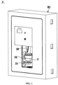
- FIG. 1 shows a schematic structural diagram of a microfluidic control detection system for a refrigerator according to an embodiment of the present application
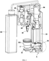
- FIG.2 shows a schematic structural diagram of internal structure of a microfluidic control detection system according to an embodiment of the present application.
- FIG.1 and FIG.2 also show a sample cup 2.
- the microfluidic control detection system 1 related to the present application comprises a microfluidic biochip 10, a weighing platform 31, a buffer solution driving device 84, a bracket 32, and a detection mechanism 20.
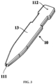
- FIG.3 shows a schematic structural diagram of a microfluidic biochip according to an embodiment of the present application
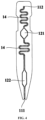
- FIG.4 shows a schematic sectional view of a microfluidic biochip according to an embodiment of the present application.
- the microfluidic biochip 10 comprises an inlet 111, a suction port 112, and a detection pool 121 formed inside the microfluidic biochip 10.
- the inlet 111, detection pool 121, and suction port 112 are sequentially interconnected through microchannels 14, thus forming a main channel.
- the inlet 111 can be located on an end face of the microfluidic biochip 10 to facilitate contact with sample liquid.
- the microchannels referred to in the present application are fine or capillary channels with a cross-sectional flow area within a predetermined size range, to ensure the microchannels have appropriate capacity to retain liquid inside.
- the weighing platform 31 is fixedly set on a support frame 33 and configured to measure weight of a sample contained in a sample cup 2 placed on it. It is understandable that the weighing platform 31 can measure combined weight of the sample cup 2 and the sample contained therein, subtracting weight of the sample cup 2 itself to obtain the weight of the sample. The weighing platform 31 can also be configured to directly detect the weight of the sample contained in the sample cup 2, such as through tare measurement.
- the buffer solution driving device 84 is configured to deliver a predetermined amount of buffer solution matching the weight of the sample to the sample cup 2, thereby producing sample liquid by mixing the buffer solution with the sample in the sample cup 2.
- the bracket 32 is configured to move in a controlled manner or operable manner, driving the sample cup 2 to move to a highest position where the sample liquid in the sample cup 2 can contact the inlet of the microfluidic biochip 10.
- the detection mechanism 20 is configured to detect the detection pool 121 to obtain predetermined detection parameters of the sample liquid. Specifically, detection reagents can be pre-placed in the detection pool 121, or can be manually or automatically added to the detection pool 121, so that after a reaction of the sample liquid with the detection reagents inside the detection pool 121, the detection mechanism 20 performs detection on the detection pool 121.
- the microfluidic control detection system 1 of the present application specially comprises a weighing platform 31 fixed on a support frame 33 and a bracket 32 capable of moving the sample cup 2. During detection, users only need to place the sample cup 2 on the weighing platform 31, which measures the weight of the sample.
- the buffer solution driving device 84 adds an appropriate amount of buffer solution to the sample cup 2, and the bracket 32 automatically moves the sample cup 2 for sample addition to the microfluidic biochip 10, making the sampling operation convenient, time-saving, and labor-saving, leading to a good user experience.
- the weighing platform 31 of the present application is fixed and does not move with movement of the bracket 32, the movement of the bracket 32 does not affect weighing accuracy of the weighing platform 31, ensuring high-precision measurement of the sample's weight, thereby improving accuracy of detection results from the microfluidic biochip 10.
- the microfluidic control detection system when used for detecting different predetermined detection parameters, the specific choices of the microfluidic biochip 10 and the detection mechanism 20 might also vary.
- the microfluidic biochip 10 it contains could be a microfluidic pesticide detection chip capable of providing conditions for pesticide liquid detection
- the detection mechanism 20 it contains could be a pesticide detection mechanism capable of detecting pesticide parameters in the pesticide liquid.
- the microfluidic biochip 10 further comprises a reaction pool 122 formed inside it.
- the reaction pool 122 is located on the main channel formed by sequentially connecting the inlet 111, the detection pool 121, and the connecting port 112 and is connected between the inlet 111 and the detection pool 121, allowing sample liquid to react with reaction reagents in the reaction pool 122 before flowing into the detection pool 121.
- the reaction pool 122 is connected to both the inlet 111 and the detection pool 121 through microchannels 14.
- the reaction reagent and detection reagent used for pesticide detection can be enzyme reagents and chromogenic agents, respectively.
- the reaction pool 122 is used for sample liquid to react with the enzyme reagent inside it; the sample liquid that has reacted with the enzyme reagent flows into the detection pool 121 and reacts with the chromogenic agent in the detection pool 121.
- the detection mechanism 20 can be selected as a photoelectric detection mechanism, which may comprise structures such as a light source, a photosensitive element, a heating plate, and a thermostat.
- the bracket 32 when the sample cup 2 is weighed on the weighing platform 31, the bracket 32 should be completely detached from and not touch the sample cup 2 to avoid affecting weighing of the sample. After the weight of the sample has been measured, the bracket 32 needs to hold the sample cup 2 to move it together. That is, the bracket 32 needs to have two states: releasing the sample cup and holding the sample cup, and it should be able to automatically switch between these two states according to a detection process. To achieve an object of switching between the two states, the common design approach before the present application was to equip the bracket with a clamping mechanism, which automatically switches between releasing the sample cup and holding the sample cup through control of the clamping mechanism's action. However, the applicants recognized that this traditional design approach is outdated and has many drawbacks.
- the clamping mechanism increases structural complexity of the bracket and requires reserved space for action switch of the clamping mechanism to avoid interference or collision with other structures, which would increase volume of the microfluidic control detection system, making it unsuitable for refrigerators with limited space.
- the holding of the sample cup, especially the release of the sample cup needs to be highly synchronized with the detection process. That is, when the weighing platform needs to measure the weight of the sample, the clamping mechanism must be in a state of releasing the sample cup; only after the weighing platform has measured the weight of the sample can the clamping mechanism hold the sample cup.
- FIG.5 shows a schematic structural diagram of the bracket, weighing platform, and their related structures according to an embodiment of the present application.
- the bracket 32 is set above the weighing platform 31 and comprises an annular frame 321 that is fitted outside the sample cup 2.
- the bracket 32 is configured to move controllably or operably in an up and down direction, using the annular frame 321 to lift the sample cup 2 off the weighing platform 31 as it moves upwards, and during its downward movement to a lowest position, it allows the sample cup 2 to be supported on the weighing platform 31 and uses an abutting effect between the sample cup 2 and the weighing platform 31 to detach the sample cup 2 from the annular frame 321.
- bracket 32 moves upwards, the annular frame 321 naturally lifts the sample cup 2 off the weighing platform 31; when the bracket 32 moves down to a certain position, the sample cup 2 is supported on the weighing platform 31, and as the bracket 32 continues to move down to the lowest position, the abutting effect between the sample cup 2 and the weighing platform 31 causes the sample cup 2 to detach from the annular frame 321, thus, the bracket 32 does not affect weight measurement of the sample in any way. It is clear that the bracket 32 of the present application naturally switches between lifting and releasing the sample cup 2 during its lifting process, without the need for any lifting control programs or releasing control programs, making structure of the bracket 32 simple, as well as control logic of the bracket 32.
- the annular frame 321 is a circular ring-shaped frame
- the sample cup 2 is a conical hollow cylinder with an outer diameter gradually increasing from bottom to top.
- An inner diameter of the annular frame 321 is smaller than an outer diameter of a top end of the sample cup 2 and larger than an outer diameter of a bottom end of the sample cup 2.
- the annular frame 321 can also be other shapes of closed frames, and the sample cup 2 can also be hollow cylindrical or other shapes.
- similar structures such as hooks can be designed on the annular frame 321 or the sample cup 2 so that the annular frame 321 naturally lifts the sample cup 2 or releases the sample cup 2 during the lifting process.
- the microfluidic control detection system 1 of the present application also comprises an oscillator 34, which is set on the bracket 32.
- the oscillator 34 is configured to oscillate the sample cup 2 after the bracket 32 lifts the sample cup 2 to a predetermined position where the sample cup 2 is separated from the weighing platform 31. This oscillation ensures that the buffer solution and the sample within the sample cup 2 are thoroughly mixed, thus allowing substances to be detected to dissolve fully into the buffer solution, resulting in a sample liquid of appropriate concentration.
- the aforementioned predetermined position is lower than the aforementioned highest position. That is, a position of the sample cup 2 during oscillation is lower than a position of the sample cup 2 where the sample liquid in the sample cup 2 contacts the inlet 111 of the microfluidic biochip 10.
- FIG.6 shows a schematic enlarged view of Part A in FIG.2 .
- the microfluidic control detection system 1 of the present application also comprises a first power terminal 35 and a second power terminal 36.
- the first power terminal 35 is set on the support frame 33 and electrically connected to a power supply of the microfluidic control detection system 1.
- the second power terminal 36 is set on the bracket 32 and electrically connected to the oscillator 34.
- first power terminal 35 and the second power terminal 36 are configured to maintain elastic contact when the bracket 32 is at a position between its lowest position where the bracket 32 enables the sample cup 2 supported on the weighing platform 31 and the position where the bracket 32 lifts the sample cup 2 to the aforementioned predetermined position, thus connecting the oscillator 34 to the power supply.
- the first power terminal 35 and the second power terminal 35 are configured to separate, when the bracket 32 lifts the sample cup 2 from the predetermined position further upwards, thus disconnecting the oscillator 34 from the power supply.
- the first power terminal 35 and the second power terminal 36 can elastically stretch and maintain contact only within a short travel range below the height of the predetermined position where the sample cup 2 is located, thus powering the oscillator 34.
- the first power terminal 35 and the second power terminal 36 separate, eliminating the need for cables sliding up and down.
- the cable between the first power terminal 35 and the power source is stationary and of appropriate length, avoiding any messy situations.
- the cable between the second power terminal 36 and the oscillator 34 can be hidden within the bracket 32, not moving relative to the bracket 32 and also avoiding any messy situations.
- the first power terminal 35 can be set at the bottom of the support frame 33, and the second power terminal 36 can protrude downwards from the bracket 32.
- the first power terminal 35 and the second power terminal 36 can also be configured to disconnect when the bracket 32 is at its lowest position supporting the sample cup 2 on the weighing platform 31 to disconnect the oscillator 34 from the power supply and maintain elastic contact when the bracket 32 lifts the sample cup 2 to the predetermined position to connect the oscillator 34 to the power supply. That is, throughout the complete lifting process of the bracket 32, only within a short travel range above the height of the predetermined position where the sample cup 2 is located, the first power terminal 35 and the second power terminal 36 can elastically stretch and maintain contact, thus powering the oscillator 34. Before the oscillator 34 starts oscillating, the bracket 32 is still relatively low, and the first power terminal 35 and the second power terminal 36 are separated, eliminating the need for cables sliding up and down.
- the cable between the first power terminal 35 and the power source is also stationary and of appropriate length, avoiding any messy situations.
- the cable between the second power terminal 36 and the oscillator 34 can be hidden within the bracket 32, not moving relative to the bracket 32 and also avoiding any messy situations.
- the first power terminal 35 can be set at the top of the support frame 33, and the second power terminal 36 can protrude upwards from the bracket 32.
- the microfluidic control detection system 1 of the present application also comprises a lifting mechanism 37 for driving the bracket 32 to move up and move down.
- the lifting mechanism 37 specifically may comprise a lifting motor 371 and a drive screw 372.
- the lifting motor 371 is configured to output driving force.
- the drive screw 372 (which in one embodiment can be configured as a lead screw) is set vertically and connected to an output shaft of the lifting motor 371 to rotate under the drive of the lifting motor 371.
- the bracket 32 is mounted on the drive screw 372 and moves up and moves down along the drive screw 372 as it rotates.
- threads may be set on the drive screw 372, and the bracket 32 can directly connect to the threads of the drive screw 372 to move along the drive screw 372 as the drive screw rotates.
- the bracket 32 can also be indirectly connected to the drive screw 372 through other structures.
- the lifting mechanism 60 comprises a nut 373, which is mounted on the drive screw 372 and connected to the threads of the drive screw 372 to move up and move down along the drive screw 372 as it rotates.
- the bracket 32 is fixedly connected to the nut 373 to drive the bracket 32 to move up and move down through the nut 373.
- the lifting mechanism 37 also comprises a guide rod 374, set beside the drive screw 372 and extending vertically.
- the bracket 32 is mounted on the guide rod 374 to guide the up movement and down movement of the bracket 32, avoiding offset, rotation, or jamming of the bracket 32 during movement and improving the smoothness of the movement of the bracket 32.
- the lifting mechanism 37 also comprises a limit switch 375, set near the top of the drive screw 372 to cause the lifting motor 371 to stop operating when the bracket 32 moves up to touch the limit switch 375.
- a position of the limit switch 375 is set so that when the lifting motor 371 stops operating triggered by the limit switch 375, the sample cup 2 on the bracket 32 is at the aforementioned highest position, i.e., a position where the sample liquid in the sample cup 2 contacts the inlet 111 of the microfluidic biochip 10.
- the present application uses the limit switch 375 to precisely locate a detection position of the bracket 32, avoiding the issue of the bracket 32 moving beyond its detection position and causing damage to the bracket 32, microfluidic biochip 10, and other structures.
- the suction port 112 is located on a side surface 13 that is parallel to the a width direction and a length direction of the microfluidic biochip 10.
- the microfluidic biochip 10 usually has a thin, flat shape, where the side surface 13 refers to a side surface parallel to both the width direction and the length direction of the microfluidic biochip 10, perpendicular to a thickness direction of the microfluidic biochip 10.
- the end face of the microfluidic biochip 10 refers to a surface located at an end of the microfluidic biochip 10.
- FIG.7 shows a schematic sectional view of a part of the microfluidic control detection system according to an embodiment of the present application
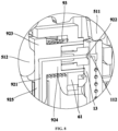
- FIG.8 shows a schematic enlarged view of Part B in FIG.7
- the microfluidic control detection system 1 of the present application also comprises a sample liquid driving device 40 and a pressing mechanism 50.
- the sample liquid driving device 40 is configured to communicate with the suction port 112 of the microfluidic biochip 10 via a sealing connector 92 once the microfluidic biochip 10 is in its installed position, thereby, under the control of the microfluidic biochip 10, prompting sample liquid in contact with the inlet 111 to enter the microchannels 14 and flow towards the detection pool 121 through the microchannels 14.
- the pressing mechanism is configured to apply pressure perpendicular to the side surface 13 to the sealing connector 92 after the installation of the microfluidic biochip 10 in its position, to form a fluidic seal connection between the sealing connector 92 and the suction port 112.
- the suction port 112 of the microfluidic biochip 10 is located on a side surface 13 parallel to a width direction of the microfluidic biochip 10 and a length direction of the microfluidic biochip 10, which offers a much larger area compared to an end face of the microfluidic biochip 10. This is advantageous for forming a relatively large sealing interface around the suction port 112, thereby significantly improving sealing performance between the sample liquid driving device 40 and the suction port 112, preventing liquid leakage, air leakage and enhancing the precision of sample introduction control by the sample liquid driving device 40.
- the pressing mechanism can apply pressure perpendicular to the side surface 13 of the microfluidic biochip 10 to a sealing connector 92 located between the sample liquid driving device 40 and the suction port 112 of the microfluidic biochip 10 after the microfluidic biochip 10 is installed in its position.
- the pressure ensures the sealing connector 92 tightly presses against the side surface 13 of the microfluidic biochip 10, further improving sealing performance of sealing interface formed between the sealing connector 92 and the side surface around the suction port 112.
- the pressing mechanism automatically applies pressure to the sealing connector 92 upon the installation of the microfluidic biochip 10, achieving coupling between chip installation and sealing connection. Users do not need to perform any actions other than installing the chip, simplifying detection operations and enhancing user experience.
- an internal part of the sealing connector 92 forms a through connection channel 921.
- a first end of the connection channel 921 communicates with the sample liquid driving device 40, and after the microfluidic biochip 10 is installed in its position, a second end of the connection channel 921 communicates with the suction port 112 of the microfluidic biochip 10.
- the sample liquid driving device 40 can be in fluid communication with the suction port 112 of the microfluidic biochip 10 through the connection channel 921.
- connection channel 921 is provided with a gradually expanding part 922, whose cross-sectional area gradually increases from inside outwards, enabling the second end of the connection channel 921 to have a larger opening area.
- the gradually expanding part 922 covers the suction port 112 of the microfluidic biochip 10, thereby forming fluid communication between the connection channel 921 and the suction port 112. It is understandable that there may be positional deviations when installing the microfluidic biochip 10, and configuration of the expanding part 922 allows for certain positional offsets between the connection channel 921 and the suction port 112, thus ensuring stable fluid communication between the suction port 112 and the connection channel 921 within an allowable range of installation errors. Simultaneously, after the microfluidic biochip 10 is installed in its position, a relatively large sealing interface is formed between the sealing connector 92 and the side surface 13, resulting in better sealing performance.
- the pressing mechanism comprises a lever that rotates around a fixed rotation axis 513.
- the lever comprises a first end 511 and a second end 512.
- the microfluidic biochip 10 is configured to abut against the first end 511 of the lever during installation, causing the lever to rotate around its rotation axis 513 until the microfluidic biochip 10 is installed in its position.
- the second end 512 of the lever abuts against the sealing connector 92 and prompts the sealing connector 92 to move in a direction gradually approaching the side surface 13 of the microfluidic biochip 10, thereby pressing the sealing connector 92 against the side surface 13.
- the first end 511 and the second end 512 of the lever can be positioned at different locations and can extend in different directions. Therefore, movement direction of the first end 511 of the lever15 and movement direction of the second end 512 of the lever can be varied according to their extension directions. This enables the coupling of chip installation and sealing connection even if the installation direction of the microfluidic biochip 10 and the direction in which the sealing connector 92 presses against the side surface 13 of the microfluidic biochip 10 are perpendicular to each other. Additionally, structure of lever is very simple, not complicating structure of the microfluidic detection system 1.
- the microfluidic control detection system 1 also comprises a first bracket 61 configured to support the sealing connector 92.
- the sealing connector 92 comprises a cap part 923 and a rod part 924, which are perpendicular to each other.
- the rod part 924 can be slidably inserted into the first bracket 61 to form a fluid connection with the suction port 112.
- a first spring 93 is fitted around the exterior of the rod part 924, with one end of the first spring 93 abutting against the inner side of the cap part 923 towards the rod part 924, and another end of the first spring 94 abutting against the first bracket 61.
- the second end of the lever abuts against the outer side of the cap part 923, away from the rod part 924.
- the first end 511 of the lever can be located near the installation position of the microfluidic biochip 10 to abut against an end face of the microfluidic biochip 10 during its installation process, and rotate as the microfluidic biochip 10 is installed.
- its second end 512 applies pressure towards the sealing connector 92 in the direction towards the microfluidic biochip 10, causing the first spring 93 to compress.
- the sealing connector 92 applies a force on the second end 512 of the lever in the direction away from the microfluidic biochip 10, causing the lever to rotate in the opposite direction, and the sealing connector 92 to detach from the side surface 13 of the microfluidic biochip 10.
- the first end 511 of the lever can also generate a force that facilitates the popping out of the microfluidic biochip 10, aiding in smooth disassembly of the microfluidic biochip 10.
- the lever can be roughly U-shaped.
- the sample liquid driving device 40 is connected to a suction pipeline 41 that is in fluid communication with it.
- the cap part 923 comprises a protruding extension in the form of a connecting column 925, which is inserted into the suction pipeline 41 to ensure that the internal connection channel 921 of the connecting column 925 is in sealed communication with the suction pipeline 41. Since the connecting column 925 is connected to the suction pipeline 41 through an insertion method, a large contact area between them ensures good sealing performance.
- the sample liquid driving device 40 may be a micro injection pump that creates a vacuum within a main channel by drawing air outwards, thereby allowing sample liquid in contact with the inlet port 111 to enter the main channel under the influence of the vacuum.
- the sample liquid driving device 40 comprises a drive motor, a vertically extending syringe, a lead screw, a slider, and a piston, among other components.
- the microfluidic detection system 1 may comprise a housing 82.
- the housing 82 has an operation platform open towards front side of the housing 82, facilitating user operations such as placing the sample cup 2 or removing the sample cup 2.
- the microfluidic detection system 1 may comprise a buffer solution bottle 83.
- the buffer solution bottle 83 located within the housing 82, is configured to contain a buffer solution.
- the buffer solution driving device 84 also located within the housing 82 and connected to the buffer solution bottle 83, is controlled to drive the buffer solution from the buffer solution bottle 83 into a sample cup 2. Mixture of buffer solution and sample in the sample cup 2 produces sample liquid.
- the buffer solution driving device 84 can be a peristaltic pump, diaphragm pump, or another suitable type of driving device.
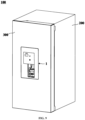
- the present application also introduces a refrigerator, as illustrated in FIG.9 , illustrating a schematic structural diagram of a refrigerator according to an embodiment of the present application.
- the refrigerator 100 incorporates the microfluidic detection system 1 involved in any of the aforementioned embodiments, integrating the microfluidic detection system 1 with the refrigerator 100. Given the high frequency of use of refrigerators 100 in daily life and their primary function for storing food ingredients, integrating the microfluidic detection system 1 into the refrigerator 100 facilitates users in conducting detection operations on food ingredient samples using the microfluidic detection system 1.
- the present application fully leverages storage function of the refrigerator 100, making a detection process more convenient. It also facilitates the interlinked control between the microfluidic detection system 1 and the refrigerator 100, achieving a high level of intelligence that meets needs of smart homes.
- the refrigerator 100 comprises a cabinet 200 and a door 300.
- the cabinet 200 defines a storage space
- the door 300 is connected to the cabinet 200 to open and/or close the storage space.
- the microfluidic detection system 1 is mounted on the door 300, which is not only convenient for operation but also does not occupy an original storage space inside the cabinet 200, thus not affecting storage capacity of the refrigerator 100 itself.
- the refrigerator 100 mentioned in the present application is broadly defined to include not only the conventional narrow sense of refrigerators but also storage devices with refrigeration, freezing, or other storage functions, such as refrigeration boxes, freezers, etc.
Landscapes
- Chemical & Material Sciences (AREA)
- Engineering & Computer Science (AREA)
- Health & Medical Sciences (AREA)
- Physics & Mathematics (AREA)
- Life Sciences & Earth Sciences (AREA)
- Analytical Chemistry (AREA)
- General Health & Medical Sciences (AREA)
- Hematology (AREA)
- Immunology (AREA)
- General Engineering & Computer Science (AREA)
- Chemical Kinetics & Catalysis (AREA)
- Combustion & Propulsion (AREA)
- Mechanical Engineering (AREA)
- Thermal Sciences (AREA)
- General Physics & Mathematics (AREA)
- Pathology (AREA)
- Biochemistry (AREA)
- Clinical Laboratory Science (AREA)
- Biomedical Technology (AREA)
- Molecular Biology (AREA)
- Urology & Nephrology (AREA)
- Dispersion Chemistry (AREA)
- Biotechnology (AREA)
- Cell Biology (AREA)
- Microbiology (AREA)
- Food Science & Technology (AREA)
- Medicinal Chemistry (AREA)
- Automatic Analysis And Handling Materials Therefor (AREA)
Applications Claiming Priority (2)
| Application Number | Priority Date | Filing Date | Title |
|---|---|---|---|
| CN202111131085.3A CN115876753A (zh) | 2021-09-26 | 2021-09-26 | 用于冰箱的微流控检测系统及冰箱 |
| PCT/CN2022/099817 WO2023045438A1 (zh) | 2021-09-26 | 2022-06-20 | 用于冰箱的微流控检测系统及冰箱 |
Publications (2)
| Publication Number | Publication Date |
|---|---|
| EP4407320A1 true EP4407320A1 (de) | 2024-07-31 |
| EP4407320A4 EP4407320A4 (de) | 2025-02-12 |
Family
ID=85719993
Family Applications (1)
| Application Number | Title | Priority Date | Filing Date |
|---|---|---|---|
| EP22871499.4A Pending EP4407320A4 (de) | 2021-09-26 | 2022-06-20 | Mikrofluidisches detektionssystem für einen kühlschrank und kühlschrank |
Country Status (4)
| Country | Link |
|---|---|
| US (1) | US20240390894A1 (de) |
| EP (1) | EP4407320A4 (de) |
| CN (1) | CN115876753A (de) |
| WO (1) | WO2023045438A1 (de) |
Families Citing this family (1)
| Publication number | Priority date | Publication date | Assignee | Title |
|---|---|---|---|---|
| CN118731298B (zh) * | 2024-07-16 | 2024-12-03 | 宁波坤行健医药科技有限公司 | 一种用于药品的安全检测设备 |
Family Cites Families (12)
| Publication number | Priority date | Publication date | Assignee | Title |
|---|---|---|---|---|
| US4169125A (en) * | 1977-04-14 | 1979-09-25 | Baxter Travenol Laboratories, Inc. | Modular chemical analysis system |
| JPH0792160A (ja) * | 1991-08-15 | 1995-04-07 | La Mina Ltd | 採取装置、試験及び採取装置、試験方法、測定方法 |
| CN102199529A (zh) * | 2011-03-22 | 2011-09-28 | 博奥生物有限公司 | 一种生物芯片杂交系统 |
| US11591557B2 (en) * | 2017-02-21 | 2023-02-28 | Dots Technology Corp. | Systems for allergen detection |
| CN208973545U (zh) * | 2018-05-04 | 2019-06-14 | 九阳股份有限公司 | 一种使用方便的食品加工机 |
| CN112756018B (zh) * | 2019-10-21 | 2025-01-28 | 广州万孚生物技术股份有限公司 | 微流控芯片及体外检测系统 |
| CN214039171U (zh) * | 2020-09-27 | 2021-08-24 | 青岛海尔电冰箱有限公司 | 用于冰箱的微流控检测系统及冰箱 |
| CN214041434U (zh) * | 2020-09-27 | 2021-08-24 | 青岛海尔电冰箱有限公司 | 用于冰箱的微流控检测系统及冰箱 |
| CN214039173U (zh) * | 2020-09-27 | 2021-08-24 | 青岛海尔电冰箱有限公司 | 用于冰箱的微流控检测系统及冰箱 |
| CN214039111U (zh) * | 2020-09-27 | 2021-08-24 | 青岛海尔电冰箱有限公司 | 冰箱 |
| CN214039172U (zh) * | 2020-09-27 | 2021-08-24 | 青岛海尔电冰箱有限公司 | 用于冰箱的农残检测系统及冰箱 |
| CN214039110U (zh) * | 2020-09-27 | 2021-08-24 | 青岛海尔电冰箱有限公司 | 冰箱 |
-
2021
- 2021-09-26 CN CN202111131085.3A patent/CN115876753A/zh active Pending
-
2022
- 2022-06-20 US US18/695,181 patent/US20240390894A1/en active Pending
- 2022-06-20 EP EP22871499.4A patent/EP4407320A4/de active Pending
- 2022-06-20 WO PCT/CN2022/099817 patent/WO2023045438A1/zh not_active Ceased
Also Published As
| Publication number | Publication date |
|---|---|
| US20240390894A1 (en) | 2024-11-28 |
| WO2023045438A1 (zh) | 2023-03-30 |
| EP4407320A4 (de) | 2025-02-12 |
| CN115876753A (zh) | 2023-03-31 |
Similar Documents
| Publication | Publication Date | Title |
|---|---|---|
| CN214039111U (zh) | 冰箱 | |
| CN214041434U (zh) | 用于冰箱的微流控检测系统及冰箱 | |
| EP4438176A1 (de) | Mikrofluidisches detektionssystem für einen kühlschrank und kühlschrank | |
| CN214039171U (zh) | 用于冰箱的微流控检测系统及冰箱 | |
| CN214039110U (zh) | 冰箱 | |
| EP4407320A1 (de) | Mikrofluidisches detektionssystem für einen kühlschrank und kühlschrank | |
| CN214039173U (zh) | 用于冰箱的微流控检测系统及冰箱 | |
| CN115248326A (zh) | Poct血细胞分析仪及其使用方法 | |
| WO2022062994A1 (zh) | 微流控检测系统及其控制方法、冰箱 | |
| US12535496B2 (en) | Microfluidic detection system for refrigerator and refrigerator | |
| EP4407265A1 (de) | Mikrofluidisches detektionssystem zur verwendung in einem kühlschrank und kühlschrank | |
| CN114324909B (zh) | 用于冰箱的微流控检测系统及冰箱 | |
| CN115248331A (zh) | Poct血细胞分析仪及其使用方法、移液器 | |
| CN114324904A (zh) | 用于冰箱的微流控检测系统及冰箱 | |
| US11883819B2 (en) | Refrigerator | |
| CN114324913B (zh) | 用于冰箱的微流控检测系统及冰箱 | |
| CN216525869U (zh) | Poct血细胞分析仪、检测座 | |
| CN115248328A (zh) | Poct血细胞分析仪及其使用方法 | |
| CN115248325A (zh) | Poct血细胞分析仪及其使用方法 | |
| CN216525868U (zh) | Poct血细胞分析仪 | |
| WO2023093382A1 (zh) | 用于冰箱的微流控检测系统及冰箱 | |
| CN216525867U (zh) | Poct血细胞分析仪 | |
| CN215180255U (zh) | Poct血细胞分析仪 | |
| CN216387080U (zh) | Poct血细胞分析仪、试剂盒 | |
| CN114324903A (zh) | 用于冰箱的微流控检测系统及其控制方法、冰箱 |
Legal Events
| Date | Code | Title | Description |
|---|---|---|---|
| STAA | Information on the status of an ep patent application or granted ep patent |
Free format text: STATUS: THE INTERNATIONAL PUBLICATION HAS BEEN MADE |
|
| PUAI | Public reference made under article 153(3) epc to a published international application that has entered the european phase |
Free format text: ORIGINAL CODE: 0009012 |
|
| STAA | Information on the status of an ep patent application or granted ep patent |
Free format text: STATUS: REQUEST FOR EXAMINATION WAS MADE |
|
| 17P | Request for examination filed |
Effective date: 20240325 |
|
| AK | Designated contracting states |
Kind code of ref document: A1 Designated state(s): AL AT BE BG CH CY CZ DE DK EE ES FI FR GB GR HR HU IE IS IT LI LT LU LV MC MK MT NL NO PL PT RO RS SE SI SK SM TR |
|
| DAV | Request for validation of the european patent (deleted) | ||
| DAX | Request for extension of the european patent (deleted) | ||
| A4 | Supplementary search report drawn up and despatched |
Effective date: 20250114 |
|
| RIC1 | Information provided on ipc code assigned before grant |
Ipc: G01N 5/00 20060101ALI20250108BHEP Ipc: G01N 33/50 20060101ALI20250108BHEP Ipc: F25D 23/12 20060101ALI20250108BHEP Ipc: F25D 23/02 20060101ALI20250108BHEP Ipc: B01L 3/00 20060101ALI20250108BHEP Ipc: F25D 11/00 20060101ALI20250108BHEP Ipc: G01N 35/00 20060101AFI20250108BHEP |