EP4407265A1 - Mikrofluidisches detektionssystem zur verwendung in einem kühlschrank und kühlschrank - Google Patents
Mikrofluidisches detektionssystem zur verwendung in einem kühlschrank und kühlschrank Download PDFInfo
- Publication number
- EP4407265A1 EP4407265A1 EP22871500.9A EP22871500A EP4407265A1 EP 4407265 A1 EP4407265 A1 EP 4407265A1 EP 22871500 A EP22871500 A EP 22871500A EP 4407265 A1 EP4407265 A1 EP 4407265A1
- Authority
- EP
- European Patent Office
- Prior art keywords
- microfluidic
- biochip
- microfluidic biochip
- sealing connector
- detection system
- Prior art date
- Legal status (The legal status is an assumption and is not a legal conclusion. Google has not performed a legal analysis and makes no representation as to the accuracy of the status listed.)
- Pending
Links
- 238000001514 detection method Methods 0.000 title claims abstract description 129
- 238000000018 DNA microarray Methods 0.000 claims abstract description 154
- 238000007789 sealing Methods 0.000 claims abstract description 98
- 239000007788 liquid Substances 0.000 claims abstract description 51
- 230000007246 mechanism Effects 0.000 claims abstract description 45
- 238000009434 installation Methods 0.000 claims description 26
- 238000004891 communication Methods 0.000 claims description 15
- 230000005489 elastic deformation Effects 0.000 claims description 5
- 238000011084 recovery Methods 0.000 claims description 5
- 230000003993 interaction Effects 0.000 claims description 4
- 238000006073 displacement reaction Methods 0.000 claims description 3
- 238000003780 insertion Methods 0.000 claims description 3
- 230000037431 insertion Effects 0.000 claims description 3
- 238000010586 diagram Methods 0.000 description 14
- 239000007853 buffer solution Substances 0.000 description 10
- 239000000575 pesticide Substances 0.000 description 10
- 239000012530 fluid Substances 0.000 description 9
- 238000006243 chemical reaction Methods 0.000 description 8
- 239000003153 chemical reaction reagent Substances 0.000 description 8
- 230000009471 action Effects 0.000 description 6
- 235000016709 nutrition Nutrition 0.000 description 6
- 210000000078 claw Anatomy 0.000 description 5
- 102000004190 Enzymes Human genes 0.000 description 4
- 108090000790 Enzymes Proteins 0.000 description 4
- 241000700605 Viruses Species 0.000 description 4
- 230000002708 enhancing effect Effects 0.000 description 4
- 235000012041 food component Nutrition 0.000 description 4
- 239000005417 food ingredient Substances 0.000 description 4
- 230000006870 function Effects 0.000 description 4
- 238000000034 method Methods 0.000 description 4
- 239000000447 pesticide residue Substances 0.000 description 4
- 230000008878 coupling Effects 0.000 description 3
- 238000010168 coupling process Methods 0.000 description 3
- 238000005859 coupling reaction Methods 0.000 description 3
- 238000005057 refrigeration Methods 0.000 description 3
- 239000003795 chemical substances by application Substances 0.000 description 2
- 238000005516 engineering process Methods 0.000 description 2
- 238000012986 modification Methods 0.000 description 2
- 230000004048 modification Effects 0.000 description 2
- 230000008569 process Effects 0.000 description 2
- 239000000243 solution Substances 0.000 description 2
- 239000000126 substance Substances 0.000 description 2
- 230000008901 benefit Effects 0.000 description 1
- 230000015572 biosynthetic process Effects 0.000 description 1
- 230000007423 decrease Effects 0.000 description 1
- 230000007812 deficiency Effects 0.000 description 1
- 238000013461 design Methods 0.000 description 1
- 238000011161 development Methods 0.000 description 1
- 239000003814 drug Substances 0.000 description 1
- 229940079593 drug Drugs 0.000 description 1
- 235000013399 edible fruits Nutrition 0.000 description 1
- 235000013305 food Nutrition 0.000 description 1
- 230000037406 food intake Effects 0.000 description 1
- 230000008014 freezing Effects 0.000 description 1
- 238000007710 freezing Methods 0.000 description 1
- 230000036541 health Effects 0.000 description 1
- 238000010438 heat treatment Methods 0.000 description 1
- 210000004251 human milk Anatomy 0.000 description 1
- 235000020256 human milk Nutrition 0.000 description 1
- 230000006872 improvement Effects 0.000 description 1
- 230000005764 inhibitory process Effects 0.000 description 1
- 238000012966 insertion method Methods 0.000 description 1
- 238000011900 installation process Methods 0.000 description 1
- 238000000520 microinjection Methods 0.000 description 1
- 235000013336 milk Nutrition 0.000 description 1
- 239000008267 milk Substances 0.000 description 1
- 210000004080 milk Anatomy 0.000 description 1
- 239000000203 mixture Substances 0.000 description 1
- 230000000474 nursing effect Effects 0.000 description 1
- 230000002572 peristaltic effect Effects 0.000 description 1
- 238000001356 surgical procedure Methods 0.000 description 1
- 235000013311 vegetables Nutrition 0.000 description 1
Images


Classifications
-
- B—PERFORMING OPERATIONS; TRANSPORTING
- B01—PHYSICAL OR CHEMICAL PROCESSES OR APPARATUS IN GENERAL
- B01L—CHEMICAL OR PHYSICAL LABORATORY APPARATUS FOR GENERAL USE
- B01L3/00—Containers or dishes for laboratory use, e.g. laboratory glassware; Droppers
- B01L3/50—Containers for the purpose of retaining a material to be analysed, e.g. test tubes
- B01L3/502—Containers for the purpose of retaining a material to be analysed, e.g. test tubes with fluid transport, e.g. in multi-compartment structures
- B01L3/5027—Containers for the purpose of retaining a material to be analysed, e.g. test tubes with fluid transport, e.g. in multi-compartment structures by integrated microfluidic structures, i.e. dimensions of channels and chambers are such that surface tension forces are important, e.g. lab-on-a-chip
- B01L3/502715—Containers for the purpose of retaining a material to be analysed, e.g. test tubes with fluid transport, e.g. in multi-compartment structures by integrated microfluidic structures, i.e. dimensions of channels and chambers are such that surface tension forces are important, e.g. lab-on-a-chip characterised by interfacing components, e.g. fluidic, electrical, optical or mechanical interfaces
-
- G—PHYSICS
- G01—MEASURING; TESTING
- G01N—INVESTIGATING OR ANALYSING MATERIALS BY DETERMINING THEIR CHEMICAL OR PHYSICAL PROPERTIES
- G01N33/00—Investigating or analysing materials by specific methods not covered by groups G01N1/00 - G01N31/00
- G01N33/48—Biological material, e.g. blood, urine; Haemocytometers
- G01N33/50—Chemical analysis of biological material, e.g. blood, urine; Testing involving biospecific ligand binding methods; Immunological testing
-
- B—PERFORMING OPERATIONS; TRANSPORTING
- B01—PHYSICAL OR CHEMICAL PROCESSES OR APPARATUS IN GENERAL
- B01L—CHEMICAL OR PHYSICAL LABORATORY APPARATUS FOR GENERAL USE
- B01L3/00—Containers or dishes for laboratory use, e.g. laboratory glassware; Droppers
-
- F—MECHANICAL ENGINEERING; LIGHTING; HEATING; WEAPONS; BLASTING
- F25—REFRIGERATION OR COOLING; COMBINED HEATING AND REFRIGERATION SYSTEMS; HEAT PUMP SYSTEMS; MANUFACTURE OR STORAGE OF ICE; LIQUEFACTION SOLIDIFICATION OF GASES
- F25D—REFRIGERATORS; COLD ROOMS; ICE-BOXES; COOLING OR FREEZING APPARATUS NOT OTHERWISE PROVIDED FOR
- F25D23/00—General constructional features
- F25D23/02—Doors; Covers
- F25D23/028—Details
-
- F—MECHANICAL ENGINEERING; LIGHTING; HEATING; WEAPONS; BLASTING
- F25—REFRIGERATION OR COOLING; COMBINED HEATING AND REFRIGERATION SYSTEMS; HEAT PUMP SYSTEMS; MANUFACTURE OR STORAGE OF ICE; LIQUEFACTION SOLIDIFICATION OF GASES
- F25D—REFRIGERATORS; COLD ROOMS; ICE-BOXES; COOLING OR FREEZING APPARATUS NOT OTHERWISE PROVIDED FOR
- F25D23/00—General constructional features
- F25D23/12—Arrangements of compartments additional to cooling compartments; Combinations of refrigerators with other equipment, e.g. stove
-
- F—MECHANICAL ENGINEERING; LIGHTING; HEATING; WEAPONS; BLASTING
- F25—REFRIGERATION OR COOLING; COMBINED HEATING AND REFRIGERATION SYSTEMS; HEAT PUMP SYSTEMS; MANUFACTURE OR STORAGE OF ICE; LIQUEFACTION SOLIDIFICATION OF GASES
- F25D—REFRIGERATORS; COLD ROOMS; ICE-BOXES; COOLING OR FREEZING APPARATUS NOT OTHERWISE PROVIDED FOR
- F25D29/00—Arrangement or mounting of control or safety devices
- F25D29/006—Safety devices
-
- B—PERFORMING OPERATIONS; TRANSPORTING
- B01—PHYSICAL OR CHEMICAL PROCESSES OR APPARATUS IN GENERAL
- B01L—CHEMICAL OR PHYSICAL LABORATORY APPARATUS FOR GENERAL USE
- B01L2200/00—Solutions for specific problems relating to chemical or physical laboratory apparatus
- B01L2200/04—Exchange or ejection of cartridges, containers or reservoirs
-
- B—PERFORMING OPERATIONS; TRANSPORTING
- B01—PHYSICAL OR CHEMICAL PROCESSES OR APPARATUS IN GENERAL
- B01L—CHEMICAL OR PHYSICAL LABORATORY APPARATUS FOR GENERAL USE
- B01L2200/00—Solutions for specific problems relating to chemical or physical laboratory apparatus
- B01L2200/06—Fluid handling related problems
- B01L2200/0642—Filling fluids into wells by specific techniques
-
- B—PERFORMING OPERATIONS; TRANSPORTING
- B01—PHYSICAL OR CHEMICAL PROCESSES OR APPARATUS IN GENERAL
- B01L—CHEMICAL OR PHYSICAL LABORATORY APPARATUS FOR GENERAL USE
- B01L2200/00—Solutions for specific problems relating to chemical or physical laboratory apparatus
- B01L2200/06—Fluid handling related problems
- B01L2200/0689—Sealing
-
- B—PERFORMING OPERATIONS; TRANSPORTING
- B01—PHYSICAL OR CHEMICAL PROCESSES OR APPARATUS IN GENERAL
- B01L—CHEMICAL OR PHYSICAL LABORATORY APPARATUS FOR GENERAL USE
- B01L2300/00—Additional constructional details
- B01L2300/06—Auxiliary integrated devices, integrated components
- B01L2300/0627—Sensor or part of a sensor is integrated
- B01L2300/0663—Whole sensors
-
- B—PERFORMING OPERATIONS; TRANSPORTING
- B01—PHYSICAL OR CHEMICAL PROCESSES OR APPARATUS IN GENERAL
- B01L—CHEMICAL OR PHYSICAL LABORATORY APPARATUS FOR GENERAL USE
- B01L2300/00—Additional constructional details
- B01L2300/08—Geometry, shape and general structure
- B01L2300/0809—Geometry, shape and general structure rectangular shaped
- B01L2300/0816—Cards, e.g. flat sample carriers usually with flow in two horizontal directions
-
- B—PERFORMING OPERATIONS; TRANSPORTING
- B01—PHYSICAL OR CHEMICAL PROCESSES OR APPARATUS IN GENERAL
- B01L—CHEMICAL OR PHYSICAL LABORATORY APPARATUS FOR GENERAL USE
- B01L2300/00—Additional constructional details
- B01L2300/08—Geometry, shape and general structure
- B01L2300/0861—Configuration of multiple channels and/or chambers in a single devices
- B01L2300/0877—Flow chambers
-
- B—PERFORMING OPERATIONS; TRANSPORTING
- B01—PHYSICAL OR CHEMICAL PROCESSES OR APPARATUS IN GENERAL
- B01L—CHEMICAL OR PHYSICAL LABORATORY APPARATUS FOR GENERAL USE
- B01L2300/00—Additional constructional details
- B01L2300/18—Means for temperature control
-
- B—PERFORMING OPERATIONS; TRANSPORTING
- B01—PHYSICAL OR CHEMICAL PROCESSES OR APPARATUS IN GENERAL
- B01L—CHEMICAL OR PHYSICAL LABORATORY APPARATUS FOR GENERAL USE
- B01L9/00—Supporting devices; Holding devices
- B01L9/52—Supports specially adapted for flat sample carriers, e.g. for plates, slides, chips
- B01L9/527—Supports specially adapted for flat sample carriers, e.g. for plates, slides, chips for microfluidic devices, e.g. used for lab-on-a-chip
-
- G—PHYSICS
- G01—MEASURING; TESTING
- G01N—INVESTIGATING OR ANALYSING MATERIALS BY DETERMINING THEIR CHEMICAL OR PHYSICAL PROPERTIES
- G01N21/00—Investigating or analysing materials by the use of optical means, i.e. using sub-millimetre waves, infrared, visible or ultraviolet light
- G01N21/75—Systems in which material is subjected to a chemical reaction, the progress or the result of the reaction being investigated
- G01N21/77—Systems in which material is subjected to a chemical reaction, the progress or the result of the reaction being investigated by observing the effect on a chemical indicator
- G01N21/78—Systems in which material is subjected to a chemical reaction, the progress or the result of the reaction being investigated by observing the effect on a chemical indicator producing a change of colour
Definitions
- the present application relates to the field of refrigeration technology, and more particularly to a microfluidic control detection system and refrigerator.
- microfluidic biochips for detection is relatively quick and compact, suitable for home use.
- air pressure propulsion relies on rotating centrifugal force to move droplets, which can only adjust unidirectional flow actions by adjusting the rotation speed.
- Air pressure propulsion utilizes positive air pressure and negative air pressure to bidirectionally propel fluid movement within the chip, offering high precision and controllability.
- air pressure propulsion needs to address the challenge of sealing the air pressure pipeline with the chip's suction port.
- Existing microfluidic detection systems mostly position the chip's suction port on its end surface to facilitate sealing the suction port with the air pressure pipeline upon chip installation.
- An object of a first aspect of the present application is to overcome at least one deficiency of the existing technology by providing a microfluidic control detection system for refrigerators that offers improved sealing performance and precise sample introduction control.
- Another object of a first aspect of the present application is to simplify the detection operations and enhance user experience.
- An object of a second aspect of the present application is to provide a refrigerator equipped with the aforementioned microfluidic control detection system.
- the present application provides a microfluidic control detection system for a refrigerator, comprising:
- an internal part of the sealing connector forms a through connection channel, a first end of the connection channel is in communication with the sample liquid driving device, and after the microfluidic biochip is installed in its position, a second end of the connection channel is in communication with the suction port of the microfluidic biochip.
- the pressing mechanism comprises a lever rotating around a fixed rotation axis, comprising a first end and a second end; the microfluidic biochip is configured to abut against the first end of the lever during installation, causing the lever to rotate around the rotation axis until the microfluidic biochip is installed in its position; and as the lever rotates around the rotation axis, the second end of the lever abuts against the sealing connector, prompting the sealing connector to move towards the side surface of the microfluidic biochip, thereby pressing the sealing connector against the side surface.
- the second end of the connection channel is provided with a gradually expanding part, cross-sectional area of the gradually expanding part gradually increases from inside outwards; and after the microfluidic biochip is installed in its position, the gradually expanding part covers the suction port of the microfluidic biochip.
- the microfluidic control detection system further comprising:
- the sample liquid driving device is connected to a suction pipeline that is in fluidic connection with the sample liquid driving device; and the cap part comprises a protruding connecting column inserted into the suction pipeline, allowing a connection channel inside the connecting column to be in sealed communication with the suction pipeline.
- the pressing mechanism comprises a spring operable to extend and retract in a predetermined direction, one end of the spring abuts against a fixed bracket, and another end of the spring abuts against the sealing connector; and the spring is configured to be compressed by the pressure from the sealing connector moving away from the side surface during installation of the microfluidic biochip, and after the microfluidic biochip is installed in its position, the spring applies pressure to the sealing connector towards the side surface due to its elastic deformation recovery force, thereby pressing the sealing connector against the side surface.
- the microfluidic biochip further comprises a slot opened on the side surface
- the predetermined direction is parallel to an installation direction of the microfluidic biochip; and a section of the body for cooperating with the suction port of the microfluidic biochip is perpendicular to the side surface, and the first slanting push rod extends from the section of the body perpendicular to the side surface in a direction inclined towards the side surface, so that interaction force between the microfluidic biochip and the sealing connector comprises component parallel to the side surface and component perpendicular to the side surface.
- the microfluidic control detection system further comprising: a chip exit mechanism, configured to operatively apply a force in a direction away from the side surface to the sealing connector, thereby causing the first slanting push rod to detach from the slot.
- the sealing connector further comprises a second slanting push rod extending from the body in a direction inclined away from the side surface;
- the chip exit mechanism comprises a pop-up button and an inclined chute for insertion of the second slanting push rod, and the pop-up button is configured to operatively move the inclined chute in a direction away from the side surface, thereby causing the second slanting push rod to have a displacement component moving away from the side surface.
- the present application provides a refrigerator, comprising the microfluidic control detection system according to any of the aforementioned technical solutions.
- the microfluidic control detection system of the present application comprises a microfluidic biochip and a sample liquid driving device in communication with a suction port of the microfluidic biochip, utilizing air pressure to propel fluid movement within the microfluidic biochip.
- the suction port of the microfluidic biochip is located on its side surface, parallel to a width direction and a length direction, which, compared to an end surface of the microfluidic biochip, offers a much larger area. This facilitates the formation of a relatively large sealing interface around the suction port, significantly improving sealing performance between the sample liquid driving device and the suction port, preventing liquid leakage, air leakage and enhancing the precision of sample introduction control by the sample liquid driving device.
- the microfluidic control detection system of the present application is also equipped with a pressing mechanism.
- the pressing mechanism can apply pressure perpendicular to the side surface of the microfluidic biochip to a sealing connector located between the sample liquid driving device and the suction port of the microfluidic biochip after the microfluidic biochip is installed in its position.
- the pressure ensures that the sealing connector tightly presses against the side surface of the microfluidic biochip, further improving sealing performance of sealing interface formed between the sealing connector and the side surface around the suction port.
- the pressing mechanism automatically applies pressure to the sealing connector upon installation of the microfluidic biochip, achieving coupling between chip installation and sealing connection. Apart from installing the chip, users do not need to perform any other actions, simplifying detection operations and enhancing user experience.
- the present application integrates the microfluidic control detection system into a refrigerator, fully leveraging the storage function of the refrigerator to make a detection process more convenient and facilitating linked control between the microfluidic detection system and the refrigerator. This higher level of automation meets the needs of smart homes.
- the present application initially provides a microfluidic control detection system for a refrigerator.
- the microfluidic control detection system of the present application is configured for the qualitative or quantitative detection of preset detection parameters of sample liquids. These preset detection parameters could include parameters indicating whether the amount of pesticide residue exceeds standards and/or the specific numerical value of the pesticide residue, parameters indicating whether nutritional elements meet standards and/or the specific content of nutritional elements, parameters for indicating whether specific harmful substances (such as specific viruses) exceed standards and/or specific content of specific harmful substances, among others.
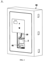
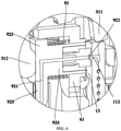
- FIG. 1 shows a schematic structural diagram of a microfluidic control detection system for a refrigerator according to an embodiment of the present application
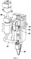
- FIG.2 shows a schematic structural diagram of internal structure of a microfluidic control detection system according to an embodiment of the present application
- FIG.3 shows a partial schematic diagram of a microfluidic control detection system according to an embodiment of the present application.
- FIG. 1 and FIG.2 also show a sample cup 2.
- the microfluidic control detection system 1 related to the present application comprises a microfluidic biochip 10, a sample liquid driving device 40, a pressing mechanism, and a detection mechanism 20.
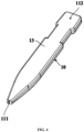
- FIG.4 shows a schematic structural diagram of a microfluidic biochip according to an embodiment of the present application
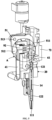
- FIG. 5 shows a schematic sectional view of part of the structure of a microfluidic control detection system according to an embodiment of the present application
- FIG.6 shows a schematic enlarged view of Part A in FIG.5 .
- the microfluidic biochip 10 comprises an inlet 111, a suction port 112, and a detection pool 121 formed inside the microfluidic biochip 10.
- the inlet 111, detection pool 121, and suction port 112 are sequentially interconnected through microchannels 14, thus forming a main channel.
- the inlet 111 can be located on an end face of the microfluidic biochip 10 to facilitate contact with sample liquid.
- the suction port 112 is located on a side surface 13 that is parallel to the a width direction and a length direction of the microfluidic biochip 10.
- the microfluidic biochip 10 usually has a thin, flat shape, where the side surface 13 refers to a side surface parallel to both the width direction and the length direction of the microfluidic biochip 10, perpendicular to a thickness direction of the microfluidic biochip 10.
- the end face of the microfluidic biochip 10 refers to a surface located at an end of the microfluidic biochip 10.
- the microchannels referred to in the present application are fine or capillary channels with a cross-sectional flow area within a predetermined size range, to ensure the microchannels have appropriate capacity to retain liquid inside.
- the sample liquid driving device 40 is configured to communicate with the suction port 112 of the microfluidic biochip 10 via a sealing connector 92 once the microfluidic biochip 10 is in its installed position, thereby, under the control of the microfluidic biochip 10, prompting sample liquid in contact with the inlet 111 to enter the microchannels 14 and flow towards the detection pool 121.
- the microfluidic biochip 10 After the microfluidic biochip 10 is installed in its position, it means that the microfluidic biochip 10 has been installed at its designated location, i.e., installation of the microfluidic biochip 10 is complete.
- the pressing mechanism is configured to apply pressure perpendicular to the side surface 13 to the sealing connector 92 after the installation of the microfluidic biochip 10 in its position, to form a fluidic seal connection between the sealing connector 92 and the suction port 112.
- the detection mechanism 20 is configured to detect the detection pool 121 to obtain preset detection parameters of the sample liquid. Specifically, detection reagents can be pre-placed in the detection pool 121, or can be manually or automatically added to the detection pool 121, so that after a reaction of the sample liquid with the detection reagents inside the detection pool 121, the detection mechanism 20 performs detection on the detection pool 121.
- the microfluidic control detection system 1 of the present application comprises a microfluidic biochip 10 and a sample liquid driving device 40 in communication with a suction port 112 of the microfluidic biochip 10, to utilize air pressure to drive movement of fluid within the microfluidic biochip 10.
- the suction port 112 of the microfluidic biochip 10 is located on a side surface 13 parallel to a width direction and a length direction, which offers a much larger area compared to an end face of the microfluidic biochip 10.
- the microfluidic control detection system 1 of the present application is also equipped with a pressing mechanism.
- the pressing mechanism can apply pressure perpendicular to the side surface 13 of the microfluidic biochip 10 to a sealing connector 92 located between the sample liquid driving device 40 and the suction port 112 of the microfluidic biochip 10 after the microfluidic biochip 10 is installed in its position.
- the pressure ensures the sealing connector 92 tightly presses against the side surface 13 of the microfluidic biochip 10, further improving sealing performance of sealing interface formed between the sealing connector 92 and the side surface around the suction port 112.
- the pressing mechanism automatically applies pressure to the sealing connector 92 upon the installation of the microfluidic biochip 10, achieving coupling between chip installation and sealing connection. Users do not need to perform any actions other than installing the chip, simplifying detection operations and enhancing user experience.
- the microfluidic control detection system when used for detecting different preset detection parameters, the specific choices of the microfluidic biochip 10 and the detection mechanism 20 might also vary.
- the microfluidic biochip 10 it contains could be a microfluidic pesticide detection chip capable of providing conditions for pesticide liquid detection
- the detection mechanism 20 it contains could be a pesticide detection mechanism capable of detecting pesticide parameters in the pesticide liquid.
- the microfluidic biochip 10 further comprises a reaction pool 122 formed inside it.
- the reaction pool 122 is located on the main channel formed by sequentially connecting the inlet 111, the detection pool 121, and the connecting port 112 and is connected between the inlet 111 and the detection pool 121, allowing sample liquid to react with reaction reagents in the reaction pool 122 before flowing into the detection pool 121.
- the reaction pool 122 is connected to both the inlet 111 and the detection pool 121 through microchannels 14.
- the reaction reagent and detection reagent used for pesticide detection can be enzyme reagents and chromogenic agents, respectively.
- the reaction pool 122 is used for sample liquid to react with the enzyme reagent inside it; the sample liquid that has reacted with the enzyme reagent flows into the detection pool 121 and reacts with the chromogenic agent in the detection pool 121.
- the detection mechanism 20 can be selected as a photoelectric detection mechanism, which may comprise structures such as a light source, a photosensitive element, a heating plate, and a thermostat.
- an internal part of the sealing connector 92 forms a through connection channel 921.
- a first end of the connection channel 921 communicates with the sample liquid driving device 40, and after the microfluidic biochip 10 is installed in its position, a second end of the connection channel 921 communicates with the suction port 112 of the microfluidic biochip 10.
- the sample liquid driving device 40 can be in fluid communication with the suction port 112 of the microfluidic biochip 10 through the connection channel 921.
- connection channel 921 is provided with a gradually expanding part 922, whose cross-sectional area gradually increases from inside outwards, enabling the second end of the connection channel 921 to have a larger opening area.
- the gradually expanding part 922 covers the suction port 112 of the microfluidic biochip 10, thereby forming fluid communication between the connection channel 921 and the suction port 112. It is understandable that there may be positional deviations when installing the microfluidic biochip 10, and configuration of the expanding part 922 allows for certain positional offsets between the connection channel 921 and the suction port 112, thus ensuring stable fluid communication between the suction port 112 and the connection channel 921 within an allowable range of installation errors. Simultaneously, after the microfluidic biochip 10 is installed in its position, a relatively large sealing interface is formed between the sealing connector 92 and the side surface 13, resulting in better sealing performance.
- the pressing mechanism includes a lever 51 that rotates around a fixed rotation axis 513.
- the lever 51 comprises a first end 511 and a second end 512.
- the microfluidic biochip 10 is configured to abut against the first end 511 of the lever 51 during installation, causing the lever 51 to rotate around its rotation axis 513 until the microfluidic biochip 10 is installed in its position.
- the second end 512 of the lever 51 abuts against the sealing connector 92 and prompts the sealing connector 92 to move in a direction gradually approaching the side surface 13 of the microfluidic biochip 10, thereby pressing the sealing connector 92 against the side surface 13.
- the lever 51 no longer rotates, and the second end 512 of the lever 51 maintains its abutting action against the sealing connector 92, thus keeping the sealing connector 92 pressed against the side surface 13.
- the first end 511 and the second end 512 of the lever 51 can be positioned at different locations and can extend in different directions. Therefore, movement direction of the first end 511 of the lever15 and movement direction of the second end 512 of the lever 51 can be varied according to their extension directions. This enables the coupling of chip installation and sealing connection even if the installation direction of the microfluidic biochip 10 and the direction in which the sealing connector 92 presses against the side surface 13 of the microfluidic biochip 10 are perpendicular to each other. Additionally, structure of lever is very simple, not complicating structure of the microfluidic detection system 1.
- the microfluidic control detection system 1 also comprises a first bracket 61 configured to support the sealing connector 92.
- the sealing connector 92 comprises a cap part 923 and a rod part 924, which are perpendicular to each other.
- the rod part 924 can be slidably inserted into the first bracket 61 to form a fluid connection with the suction port 112.
- a first spring 93 is fitted around the exterior of the rod part 924, with one end of the first spring 93 abutting against the inner side of the cap part 923 towards the rod part 924, and another end of the first spring 94 abutting against the first bracket 61.
- the second end of the lever 51 abuts against the outer side of the cap part 923, away from the rod part 924.
- the first end 511 of the lever 51 can be located near the installation position of the microfluidic biochip 10 to abut against an end face of the microfluidic biochip 10 during its installation process, and rotate as the microfluidic biochip 10 is installed.
- its second end 512 applies pressure towards the sealing connector 92 in the direction towards the microfluidic biochip 10, causing the first spring 93 to compress.
- the sealing connector 92 applies a force on the second end 512 of the lever 51 in the direction away from the microfluidic biochip 10, causing the lever 51 to rotate in the opposite direction, and the sealing connector 92 to detach from the side surface 13 of the microfluidic biochip 10.
- the first end 511 of the lever 51 can also generate a force that facilitates the popping out of the microfluidic biochip 10, aiding in smooth disassembly of the microfluidic biochip 10.
- the lever 51 can be roughly U-shaped.
- the sample liquid driving device 40 is connected to a suction pipeline 41 that is in fluid communication with it.
- the cap part 923 comprises a protruding extension in the form of a connecting column 925, which is inserted into the suction pipeline 41 to ensure that the internal connection channel 921 of the connecting column 925 is in sealed communication with the suction pipeline 41. Since the connecting column 925 is connected to the suction pipeline 41 through an insertion method, a large contact area between them ensures good sealing performance.
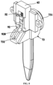
- FIG.7 illustrates a schematic structure of a microfluidic biochip and its clamping mechanism according to an embodiment of the present application.
- the microfluidic detection system 1 further comprises a clamping mechanism 71, which is configured to clamp the microfluidic biochip 10, ensuring it maintains a fluid-sealed connection with the sample liquid driving device 40.
- the clamping mechanism 71 may consist of two oppositely positioned elastic claws 711, applying opposing forces to the microfluidic biochip 10 clamped between them.
- the microfluidic detection system 1 comprises a cantilevered push-button 72, suspended on one side of the microfluidic biochip 10.
- the cantilevered push-button 72 simultaneously contacts the inner sides of the two elastic claws 711, arranged to face each other. This design allows the cantilevered push-button 72 to exert an outward force on the inner sides of the two elastic claws 711 when a force is applied to the cantilevered push-button 72 in the direction towards the microfluidic biochip 10, causing the two elastic claws 711 to elastically deform outwardly away from each other.
- the microfluidic biochip 10 can be installed in its position by moving upwards in a vertical direction, with the inlet 111 located at the bottom of the microfluidic biochip 10.
- the cantilevered push-button 72 is located on the front side of the microfluidic biochip 10 for easy pressing by the user.
- the suction port 112 is located on the side surface 13 at the back of the microfluidic biochip 10, with the sealing connector 92 positioned behind the microfluidic biochip 10.
- the first end 511 of the lever 51 is located above the microfluidic biochip 10, contacting top end of the microfluidic biochip 10, while the second end 512 of the lever 51 contacts a rear surface of the sealing connector 92, applying a forward force on it.
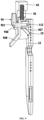
- FIG.8 depicts a partial schematic diagram of a microfluidic detection mechanism according to another embodiment of the present application
- FIG.9 depicts schematic diagram of a portion of a microfluidic detection mechanism according to another embodiment of the present application.
- the pressing mechanism comprises a second spring 52 that is operable to extend and retract along a predetermined direction. One end of the second spring 52 abuts against a fixed second bracket 62, while another end of the second spring 52 abuts against the sealing connector 92.
- the second spring 52 is configured to be compressed under the pressure from the sealing connector 92 moving away from the side surface 13 during installation of the microfluidic biochip 10.
- the second spring 52 After the microfluidic biochip 10 is installed in its position, the second spring 52, under its own elastic deformation recovery force, applies pressure towards the side surface 13 to the sealing connector 92, thus pressing the sealing connector 92 against the side surface 13. It's understood that structure of the sealing connector 92 in embodiments shown in FIG. 8 and FIG.9 slightly differs from structure of the sealing connector 92 in embodiments shown in FIG.3 to FIG.7 .
- the microfluidic biochip 10 comprises a slot 15 opened on the side surface 13.
- the sealing connector 92 comprises a body 926, within which a connection channel 921 is formed, and a first slanting push rod 927 extending outward from the body 926.
- the first slanting push rod 927 abuts against the side surface 13 and moves parallel to the side surface 13.
- the first slanting push rod 927 inserts into the slot 15, thereby securing the microfluidic biochip 10.
- an objective of holding the microfluidic biochip 10 is achieved by providing a slot 15 on the side surface 13 of the microfluidic biochip 10, incorporating the first slanting push rod 927 on the sealing connector 92, and through the interaction between the first slanting push rod 927 and the slot 15, without a need for additional chip clamping mechanisms, simplifying structure of the microfluidic detection system 1.
- the predetermined direction is parallel to an installation direction of the microfluidic biochip 10.
- a section of the main 926, which is configured to cooperate with the suction port 112 of the microfluidic biochip 10, is perpendicular to the side surface 13.
- the first slanting push rod 927 extends from the section of the body 926, which is perpendicular to the side surface 13, inclined towards the side surface 13. This arrangement ensures that interaction force exerted between the microfluidic biochip 10 and the sealing connector 92 comprises component parallel to the side surface 13 and component perpendicular to the side surface 13.
- the first slanting push rod 927 abuts against the side surface 13, and force generated by the microfluidic biochip 10 on the sealing connector 92 include components both parallel and perpendicular to the side surface 13.
- the parallel component compresses the second spring 52, while the perpendicular component causes a slight tilting deformation of the second spring 52.
- the microfluidic detection system 1 comprises a chip exit mechanism 73, configured to apply a force on the sealing connector 92 in a direction away from the side surface 13, facilitating the disengagement of the first slanting push rod 927 from the slot 15. This makes it easier for users to manually disassemble the microfluidic biochip 10.
- a third spring can be positioned at an end face of the microfluidic biochip 10. After installation of the microfluidic biochip 10, this third spring is compressed; upon the disengagement of the first slanting push rod 927 from the slot 15, the third spring automatically ejects the microfluidic biochip 10, simplifying the operation for the user.
- the sealing connector 92 further comprises a second slanting push rod 928 extending from the body 926 in a direction inclined away from the side surface 13.
- the chip exit mechanism 73 is equipped with a pop-up button 731 and an inclined chute 732 for insertion of the second slanting push rod 928.
- the pop-up button 731 is configured to be operable to move the inclined chute 732 in a direction away from the side surface 13, thereby enabling the second slanting push rod 928 to have a displacement component moving away from the side surface 13. This allows users to simply press the push button 731 to disengage the first slanting push rod 927 from the slot 15, simplifying the operation.
- the sample liquid driving device 40 may be a micro injection pump that creates a vacuum within a main channel by drawing air outwards, thereby allowing sample liquid in contact with the inlet port 111 to enter the main channel under the influence of the vacuum.
- the sample liquid driving device 40 comprises a drive motor, a vertically extending syringe, a lead screw, a slider, and a piston, among other components.
- the microfluidic biochip 10 also comprises a sample platform81.
- the sample platform 81 is positioned below the microfluidic biochip 10 for placing a sample cup 2, which holds the sample liquid. Furthermore, the sample platform 81 is configured to move in a controlled or operable manner to transport the sample cup 2 placed on the sample platform 81 to a position where sample liquid within the sample cup 2 is allowed to contact the inlet port 111 of the microfluidic biochip 10.
- the microfluidic detection system 1 may comprise a housing 82.
- the housing 82 has an operation platform open towards front side of the housing 82, with the sample platform 81 at least partially located within the operation platform, facilitating user operations such as placing the sample cup 2 or removing the sample cup 2.
- the microfluidic detection system 1 may comprise a buffer solution bottle 83 and a buffer solution driving device 84.
- the buffer solution bottle 83 located within the housing 82, is configured to contain a buffer solution.
- the buffer solution driving device 84 also located within the housing 82 and connected to the buffer solution bottle 83, is controlled to drive the buffer solution from the buffer solution bottle 83 into a sample cup 2 on the sample platform 81. Mixture of buffer solution and sample in the sample cup 2 produces sample liquid.
- the buffer solution driving device 84 can be a peristaltic pump, diaphragm pump, or another suitable type of driving device.
- the present application also introduces a refrigerator, as illustrated in FIG. 10 , illustrating a schematic structural diagram of a refrigerator according to an embodiment of the present application.
- the refrigerator 100 incorporates the microfluidic detection system 1 involved in any of the aforementioned embodiments, integrating the microfluidic detection system 1 with the refrigerator 100. Given the high frequency of use of refrigerators 100 in daily life and their primary function for storing food ingredients, integrating the microfluidic detection system 1 into the refrigerator 100 facilitates users in conducting detection operations on food ingredient samples using the microfluidic detection system 1.
- the present application fully leverages storage function of the refrigerator 100, making a detection process more convenient. It also facilitates the interlinked control between the microfluidic detection system 1 and the refrigerator 100, achieving a high level of intelligence that meets needs of smart homes.
- the refrigerator 100 comprises a cabinet 200 and a door 300.
- the cabinet 200 defines a storage space
- the door 300 is connected to the cabinet 200 to open and/or close the storage space.
- the microfluidic detection system 1 is mounted on the door 300, which is not only convenient for operation but also does not occupy an original storage space inside the cabinet 200, thus not affecting storage capacity of the refrigerator 100 itself.
- the refrigerator 100 mentioned in the present application is broadly defined to include not only the conventional narrow sense of refrigerators but also storage devices with refrigeration, freezing, or other storage functions, such as refrigeration boxes, freezers, etc.
Landscapes
- Engineering & Computer Science (AREA)
- Chemical & Material Sciences (AREA)
- Health & Medical Sciences (AREA)
- Physics & Mathematics (AREA)
- Life Sciences & Earth Sciences (AREA)
- General Engineering & Computer Science (AREA)
- Thermal Sciences (AREA)
- Mechanical Engineering (AREA)
- Combustion & Propulsion (AREA)
- Hematology (AREA)
- Analytical Chemistry (AREA)
- General Health & Medical Sciences (AREA)
- Clinical Laboratory Science (AREA)
- Chemical Kinetics & Catalysis (AREA)
- Urology & Nephrology (AREA)
- Immunology (AREA)
- Biomedical Technology (AREA)
- Molecular Biology (AREA)
- Dispersion Chemistry (AREA)
- Microbiology (AREA)
- Cell Biology (AREA)
- Biotechnology (AREA)
- Food Science & Technology (AREA)
- Medicinal Chemistry (AREA)
- Biochemistry (AREA)
- General Physics & Mathematics (AREA)
- Pathology (AREA)
- Automatic Analysis And Handling Materials Therefor (AREA)
Applications Claiming Priority (2)
| Application Number | Priority Date | Filing Date | Title |
|---|---|---|---|
| CN202111115637.1A CN115901734A (zh) | 2021-09-23 | 2021-09-23 | 用于冰箱的微流控检测系统及冰箱 |
| PCT/CN2022/099818 WO2023045439A1 (zh) | 2021-09-23 | 2022-06-20 | 用于冰箱的微流控检测系统及冰箱 |
Publications (2)
| Publication Number | Publication Date |
|---|---|
| EP4407265A1 true EP4407265A1 (de) | 2024-07-31 |
| EP4407265A4 EP4407265A4 (de) | 2025-02-12 |
Family
ID=85719989
Family Applications (1)
| Application Number | Title | Priority Date | Filing Date |
|---|---|---|---|
| EP22871500.9A Pending EP4407265A4 (de) | 2021-09-23 | 2022-06-20 | Mikrofluidisches detektionssystem zur verwendung in einem kühlschrank und kühlschrank |
Country Status (4)
| Country | Link |
|---|---|
| US (1) | US20240399363A1 (de) |
| EP (1) | EP4407265A4 (de) |
| CN (1) | CN115901734A (de) |
| WO (1) | WO2023045439A1 (de) |
Families Citing this family (1)
| Publication number | Priority date | Publication date | Assignee | Title |
|---|---|---|---|---|
| CN120272311B (zh) * | 2025-06-12 | 2025-08-22 | 大连国际旅行卫生保健中心(大连海关口岸门诊部) | 一种使用微流体芯片检测传染性病原体的检测装置 |
Family Cites Families (17)
| Publication number | Priority date | Publication date | Assignee | Title |
|---|---|---|---|---|
| US20080131327A1 (en) * | 2006-09-28 | 2008-06-05 | California Institute Of Technology | System and method for interfacing with a microfluidic chip |
| WO2008053660A1 (en) * | 2006-11-02 | 2008-05-08 | Konica Minolta Medical & Graphic, Inc. | Micropump unit, and microchip inspection system |
| CN108801929A (zh) * | 2018-06-26 | 2018-11-13 | 杭州霆科生物科技有限公司 | 一种能够检测食品安全的智能家居 |
| CN209244466U (zh) * | 2018-08-02 | 2019-08-13 | 惠州市方特新材料有限公司 | 一种可偏移密封推拉门系统 |
| CN109735443B (zh) * | 2018-12-10 | 2022-07-22 | 江苏大学 | 一种便携负压微流控检测系统及其工作方法 |
| CN210130766U (zh) * | 2018-12-18 | 2020-03-10 | 青岛蓝豆创新科技有限公司 | 多功能加湿纸盒 |
| CN109647553B (zh) * | 2018-12-29 | 2020-11-20 | 北京化工大学 | 多指标疾病联合检测微流控装置 |
| CN109668883A (zh) * | 2019-02-14 | 2019-04-23 | 杭州霆科生物科技有限公司 | 一种农药残留检测笔 |
| US11565256B2 (en) * | 2019-06-28 | 2023-01-31 | Vanderbilt University | Microfluidic systems, pumps, valves, fluidic chips thereof, and applications of same |
| CN110180612B (zh) * | 2019-07-24 | 2019-10-29 | 山东交通职业学院 | 一种微流控芯片及其微流驱动控制系统 |
| CN214088513U (zh) * | 2020-04-29 | 2021-08-31 | 中国科学院过程工程研究所 | 一种自助式核酸检测一体机及微流控芯片 |
| CN214039173U (zh) * | 2020-09-27 | 2021-08-24 | 青岛海尔电冰箱有限公司 | 用于冰箱的微流控检测系统及冰箱 |
| CN214039111U (zh) * | 2020-09-27 | 2021-08-24 | 青岛海尔电冰箱有限公司 | 冰箱 |
| CN214041434U (zh) * | 2020-09-27 | 2021-08-24 | 青岛海尔电冰箱有限公司 | 用于冰箱的微流控检测系统及冰箱 |
| CN114324904B (zh) * | 2020-09-27 | 2025-09-09 | 青岛海尔电冰箱有限公司 | 用于冰箱的微流控检测系统及冰箱 |
| CN114280313A (zh) * | 2020-09-27 | 2022-04-05 | 青岛海尔电冰箱有限公司 | 用于冰箱的微流控检测系统及冰箱 |
| CN113422253B (zh) * | 2021-07-23 | 2025-10-17 | 昆山思瑞奕电子有限公司 | 互锁组件 |
-
2021
- 2021-09-23 CN CN202111115637.1A patent/CN115901734A/zh active Pending
-
2022
- 2022-06-20 US US18/694,738 patent/US20240399363A1/en active Pending
- 2022-06-20 EP EP22871500.9A patent/EP4407265A4/de active Pending
- 2022-06-20 WO PCT/CN2022/099818 patent/WO2023045439A1/zh not_active Ceased
Also Published As
| Publication number | Publication date |
|---|---|
| US20240399363A1 (en) | 2024-12-05 |
| EP4407265A4 (de) | 2025-02-12 |
| WO2023045439A1 (zh) | 2023-03-30 |
| CN115901734A (zh) | 2023-04-04 |
Similar Documents
| Publication | Publication Date | Title |
|---|---|---|
| AU2004312764B2 (en) | Apparatus for modifying pressure within a fluid dispenser | |
| US12133613B2 (en) | Vacuum food processing system | |
| EP2925448B1 (de) | Vorrichtung und verfahren zur durchführung eines assays zur detektion einer nucleinsäure in einer probe | |
| CN214039111U (zh) | 冰箱 | |
| EP1333287B1 (de) | Verfahren und Vorrichtung zur Druckänderung in einem Flüssigkeitspender | |
| EP4407265A1 (de) | Mikrofluidisches detektionssystem zur verwendung in einem kühlschrank und kühlschrank | |
| CN213913852U (zh) | 一种微流控芯片液体驱动装置 | |
| EP4438176A1 (de) | Mikrofluidisches detektionssystem für einen kühlschrank und kühlschrank | |
| WO2021027082A1 (zh) | 一种样本收集及检测装置和方法 | |
| WO2022062909A1 (zh) | 冰箱 | |
| EP4407320A1 (de) | Mikrofluidisches detektionssystem für einen kühlschrank und kühlschrank | |
| CA2676751A1 (en) | Method and dosing device for dosing a fluid into a receiving channel of a test element for analyzing body fluids | |
| CN111187713B (zh) | 微流控芯片的刺破装置及微流控芯片检测系统 | |
| US12535496B2 (en) | Microfluidic detection system for refrigerator and refrigerator | |
| CN114324904A (zh) | 用于冰箱的微流控检测系统及冰箱 | |
| CN114324909A (zh) | 用于冰箱的微流控检测系统及冰箱 | |
| CN116121039A (zh) | 样品检测耗材及样品检测方法 | |
| TW202237272A (zh) | 移液系統 | |
| CN114279136A (zh) | 冰箱 | |
| CN116396841A (zh) | 一种厌氧菌取样检测装置 | |
| CN116159607A (zh) | 用于冰箱的微流控检测系统及冰箱 | |
| CN121511047A (zh) | 用于洗涤厨房物品的器具 | |
| CN117861742A (zh) | 样本定量转移装置 | |
| CN114324903A (zh) | 用于冰箱的微流控检测系统及其控制方法、冰箱 | |
| ITUD20070221A1 (it) | Dispositivo medicale pre-analitico per la raccolta e la predisposizione all'analisi di un campione biologico e relativo procedimento |
Legal Events
| Date | Code | Title | Description |
|---|---|---|---|
| STAA | Information on the status of an ep patent application or granted ep patent |
Free format text: STATUS: THE INTERNATIONAL PUBLICATION HAS BEEN MADE |
|
| PUAI | Public reference made under article 153(3) epc to a published international application that has entered the european phase |
Free format text: ORIGINAL CODE: 0009012 |
|
| STAA | Information on the status of an ep patent application or granted ep patent |
Free format text: STATUS: REQUEST FOR EXAMINATION WAS MADE |
|
| 17P | Request for examination filed |
Effective date: 20240321 |
|
| AK | Designated contracting states |
Kind code of ref document: A1 Designated state(s): AL AT BE BG CH CY CZ DE DK EE ES FI FR GB GR HR HU IE IS IT LI LT LU LV MC MK MT NL NO PL PT RO RS SE SI SK SM TR |
|
| DAV | Request for validation of the european patent (deleted) | ||
| DAX | Request for extension of the european patent (deleted) | ||
| A4 | Supplementary search report drawn up and despatched |
Effective date: 20250113 |
|
| RIC1 | Information provided on ipc code assigned before grant |
Ipc: B01L 9/00 20060101ALI20250107BHEP Ipc: G01N 33/50 20060101ALI20250107BHEP Ipc: G01N 21/78 20060101ALI20250107BHEP Ipc: F25D 23/12 20060101ALI20250107BHEP Ipc: F25D 23/02 20060101ALI20250107BHEP Ipc: B01L 3/00 20060101ALI20250107BHEP Ipc: G01N 33/04 20060101ALI20250107BHEP Ipc: F25D 11/02 20060101ALI20250107BHEP Ipc: F25D 29/00 20060101AFI20250107BHEP |