EP4407247A1 - Luftstromsimulationsendgerätevorrichtung und luftstromsimulationsverfahren - Google Patents
Luftstromsimulationsendgerätevorrichtung und luftstromsimulationsverfahren Download PDFInfo
- Publication number
- EP4407247A1 EP4407247A1 EP22886646.3A EP22886646A EP4407247A1 EP 4407247 A1 EP4407247 A1 EP 4407247A1 EP 22886646 A EP22886646 A EP 22886646A EP 4407247 A1 EP4407247 A1 EP 4407247A1
- Authority
- EP
- European Patent Office
- Prior art keywords
- airflow
- indoor room
- dimensional model
- terminal device
- analysis
- Prior art date
- Legal status (The legal status is an assumption and is not a legal conclusion. Google has not performed a legal analysis and makes no representation as to the accuracy of the status listed.)
- Pending
Links
Images


Classifications
-
- F—MECHANICAL ENGINEERING; LIGHTING; HEATING; WEAPONS; BLASTING
- F24—HEATING; RANGES; VENTILATING
- F24F—AIR-CONDITIONING; AIR-HUMIDIFICATION; VENTILATION; USE OF AIR CURRENTS FOR SCREENING
- F24F11/00—Control or safety arrangements
- F24F11/62—Control or safety arrangements characterised by the type of control or by internal processing, e.g. using fuzzy logic, adaptive control or estimation of values
- F24F11/63—Electronic processing
- F24F11/64—Electronic processing using pre-stored data
-
- F—MECHANICAL ENGINEERING; LIGHTING; HEATING; WEAPONS; BLASTING
- F24—HEATING; RANGES; VENTILATING
- F24F—AIR-CONDITIONING; AIR-HUMIDIFICATION; VENTILATION; USE OF AIR CURRENTS FOR SCREENING
- F24F11/00—Control or safety arrangements
- F24F11/30—Control or safety arrangements for purposes related to the operation of the system, e.g. for safety or monitoring
-
- F—MECHANICAL ENGINEERING; LIGHTING; HEATING; WEAPONS; BLASTING
- F24—HEATING; RANGES; VENTILATING
- F24F—AIR-CONDITIONING; AIR-HUMIDIFICATION; VENTILATION; USE OF AIR CURRENTS FOR SCREENING
- F24F11/00—Control or safety arrangements
- F24F11/50—Control or safety arrangements characterised by user interfaces or communication
- F24F11/52—Indication arrangements, e.g. displays
-
- F—MECHANICAL ENGINEERING; LIGHTING; HEATING; WEAPONS; BLASTING
- F24—HEATING; RANGES; VENTILATING
- F24F—AIR-CONDITIONING; AIR-HUMIDIFICATION; VENTILATION; USE OF AIR CURRENTS FOR SCREENING
- F24F11/00—Control or safety arrangements
- F24F11/50—Control or safety arrangements characterised by user interfaces or communication
- F24F11/56—Remote control
-
- F—MECHANICAL ENGINEERING; LIGHTING; HEATING; WEAPONS; BLASTING
- F24—HEATING; RANGES; VENTILATING
- F24F—AIR-CONDITIONING; AIR-HUMIDIFICATION; VENTILATION; USE OF AIR CURRENTS FOR SCREENING
- F24F11/00—Control or safety arrangements
- F24F11/62—Control or safety arrangements characterised by the type of control or by internal processing, e.g. using fuzzy logic, adaptive control or estimation of values
- F24F11/63—Electronic processing
-
- F—MECHANICAL ENGINEERING; LIGHTING; HEATING; WEAPONS; BLASTING
- F24—HEATING; RANGES; VENTILATING
- F24F—AIR-CONDITIONING; AIR-HUMIDIFICATION; VENTILATION; USE OF AIR CURRENTS FOR SCREENING
- F24F11/00—Control or safety arrangements
- F24F11/70—Control systems characterised by their outputs; Constructional details thereof
- F24F11/72—Control systems characterised by their outputs; Constructional details thereof for controlling the supply of treated air, e.g. its pressure
- F24F11/74—Control systems characterised by their outputs; Constructional details thereof for controlling the supply of treated air, e.g. its pressure for controlling air flow rate or air velocity
-
- F—MECHANICAL ENGINEERING; LIGHTING; HEATING; WEAPONS; BLASTING
- F24—HEATING; RANGES; VENTILATING
- F24F—AIR-CONDITIONING; AIR-HUMIDIFICATION; VENTILATION; USE OF AIR CURRENTS FOR SCREENING
- F24F11/00—Control or safety arrangements
- F24F11/70—Control systems characterised by their outputs; Constructional details thereof
- F24F11/72—Control systems characterised by their outputs; Constructional details thereof for controlling the supply of treated air, e.g. its pressure
- F24F11/79—Control systems characterised by their outputs; Constructional details thereof for controlling the supply of treated air, e.g. its pressure for controlling the direction of the supplied air
-
- G—PHYSICS
- G06—COMPUTING OR CALCULATING; COUNTING
- G06F—ELECTRIC DIGITAL DATA PROCESSING
- G06F30/00—Computer-aided design [CAD]
- G06F30/10—Geometric CAD
- G06F30/13—Architectural design, e.g. computer-aided architectural design [CAAD] related to design of buildings, bridges, landscapes, production plants or roads
-
- G—PHYSICS
- G06—COMPUTING OR CALCULATING; COUNTING
- G06F—ELECTRIC DIGITAL DATA PROCESSING
- G06F30/00—Computer-aided design [CAD]
- G06F30/20—Design optimisation, verification or simulation
- G06F30/25—Design optimisation, verification or simulation using particle-based methods
-
- G—PHYSICS
- G06—COMPUTING OR CALCULATING; COUNTING
- G06F—ELECTRIC DIGITAL DATA PROCESSING
- G06F30/00—Computer-aided design [CAD]
- G06F30/20—Design optimisation, verification or simulation
- G06F30/28—Design optimisation, verification or simulation using fluid dynamics, e.g. using Navier-Stokes equations or computational fluid dynamics [CFD]
-
- F—MECHANICAL ENGINEERING; LIGHTING; HEATING; WEAPONS; BLASTING
- F24—HEATING; RANGES; VENTILATING
- F24F—AIR-CONDITIONING; AIR-HUMIDIFICATION; VENTILATION; USE OF AIR CURRENTS FOR SCREENING
- F24F2110/00—Control inputs relating to air properties
- F24F2110/30—Velocity
-
- G—PHYSICS
- G06—COMPUTING OR CALCULATING; COUNTING
- G06F—ELECTRIC DIGITAL DATA PROCESSING
- G06F2113/00—Details relating to the application field
- G06F2113/08—Fluids
Definitions
- the present invention relates to an airflow simulation terminal device and an airflow simulation method.
- Patent Literature 1 describes that photographic data, etc. of an indoor space to be subjected to airflow analysis is input to a dedicated PC (personal computer), the input data is automatically analyzed and saved as three-dimensional CAD data on the PC, and an airflow pattern when an air purifier is placed is analyzed using the three-dimensional CAD data by means of an airflow analysis application.
- Patent Literature 1 also describes that the PC and a small terminal configured separately from the PC communicates with each other and a maintenance method, etc., for the air purifier based on airflow analysis information is displayed on the small terminal.
- Patent Literature 1 JP 2019-76525A
- An airflow simulation terminal device in an embodiment of the invention is an airflow simulation terminal device to analyze airflow in an indoor room when an airflow generator that generates airflow is placed in the indoor room
- the airflow simulation terminal device comprises: a portable terminal device that integrally comprises an imaging device to capture an image of the indoor room, a three-dimensional model creation unit that creates a three-dimensional model of the indoor room based on image data of the indoor room captured by the imaging device, and an airflow analysis unit that analyzes airflow in the indoor room when the airflow generator is placed in the three-dimensional model of the indoor room created by the three-dimensional model creation unit.
- An airflow simulation method in an embodiment of the invention is an airflow simulation method for analyzing airflow in an indoor room when an airflow generator that generates airflow is placed in the indoor room, the method comprises:
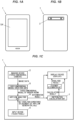
- Fig. 1A is a front view showing an airflow simulation terminal device in the present embodiment
- Fig. 1B is a rear view thereof
- Fig. 1C is a functional block diagram thereof.
- An airflow simulation terminal device 1 analyzes airflow in an indoor room when an airflow generator that generates airflow is placed in the indoor room.
- the airflow simulation terminal device 1 is composed of a portable terminal device.
- the airflow simulation terminal device 1 is a tablet terminal in the example shown in the figure, but it is not limited thereto.
- the airflow simulation terminal device 1 may be a smartphone, a notebook personal computer or a dedicated mobile terminal, as long as it is a portable terminal device.
- the airflow simulation terminal device 1 which is a portable terminal device, integrally includes an imaging device 2 to capture an image of an indoor room, a display device 3, an input device 4, a three-dimensional model creation unit 5, an airflow analysis unit 6, a distribution calculation unit 7 and a placement determination unit 8.
- the three-dimensional model creation unit 5, the airflow analysis unit 6, the distribution calculation unit 7 and the placement determination unit 8 are realized by appropriately combining an arithmetic element such as CPU, a memory, a storage device, software, etc.
- the imaging device 2 is a device to capture an image of an indoor room for modeling the indoor room to be subjected to airflow analysis.
- the imaging device 2 it is more desirable to use a three-dimensional camera capable of obtaining information on depth.
- the three-dimensional camera it is possible to use, e.g., a camera which has two imaging elements and is capable of obtaining information on depth based on parallax between the two imaging elements.
- the imaging device 2 may be configured as an integral part of a tablet terminal, etc., or may be configured to be detachable.
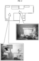
- Fig. 2 is an explanatory diagram for explaining image capturing in the indoor room to be subjected to airflow analysis.
- the white arrows in the drawing show examples of shooting position and direction.
- a worker performing airflow analysis takes images of the indoor room thoroughly so that sufficient image data to model the indoor room can be obtained.
- the image data (three-dimensional image data) obtained by the imaging device 2 is output to the three-dimensional model creation unit 5.
- the configuration may be such that an imaging control unit allowing panoramic images (e.g., 360° rotating images) to be obtained is further included and an obtained panoramic image is used for modeling.
- the display device 3 is to display an analysis result of the airflow analysis unit 6, a calculation result of the distribution calculation unit 7 and a determination result of the placement determination unit 8, etc. (which will be described later) and is composed of, e.g., a liquid crystal display.
- a touch panel display which also serves as the input device 4 is used as the display device 3.
- the input device 4 such as keyboard may be provided separately from the display device 3.
- the three-dimensional model creation unit 5 analyzes the shape, etc., of the indoor room based on the image data (the three-dimensional image data) of the indoor room captured by the imaging device, and creates a three-dimensional model of the indoor room.
- the description of the specific method of creating the three-dimensional model of the indoor room from the image data of the indoor room is omitted here since it is well known.
- the three-dimensional model creation unit 5 may display the created three-dimensional model of the indoor room.
- the three-dimensional model creation unit 5 may be configured such that the three-dimensional model displayed on the display unit 3 can be modified by operating the input device 4 (e.g., tap operation or drag operation).
- the three-dimensional model creation unit 5 is also configured such that an airflow generator can be placed in the created three-dimensional model of the indoor room by operating the input device 4 (e.g., tap operation or drag operation).
- Fig. 3 is a diagram illustrating an example of a three-dimensional model 10 in which an airflow generator 9 is placed.
- the airflow generator 9 is composed of, e.g., any of an air purifier, a space sterilization device, a space deodorization device, a space sterilization and deodorization device, or a humidification and sterilization device.
- the airflow generator 9 may also include an air blower, a dehumidifier, a humidifier, etc.
- these may be taken into account in the airflow simulation.
- the airflow generator 9 be modularized as a 3D model in advance, and the positions of air outlet and inlet ports, air volume and the direction of air be set in advance.
- This modularized airflow generator 9 is installed in the three-dimensional model 10 by operating the input device 4.
- Fig. 3 shows a case where only one airflow generator 9 is placed in the three-dimensional model 10, plural airflow generators 9 may be placed in the three-dimensional model 10.
- analysis of airflow in an indoor room with a ventilation device is possible by placing two airflow generators 9, an air purifier and a ventilation device.
- the example in FIG. 3 shows a case where a desktop-type airflow generator 9 is placed, the airflow generator 9 may be of a ceiling-mounted type or a floor-mounted type.
- the three-dimensional model creation unit 5 may be configured such that any object obstructing airflow or an object to be a heat source can be placed by operating the input device 4.
- any object obstructing airflow or an object to be a heat source can be placed by operating the input device 4.
- analysis of an indoor room where people are in almost fixed positions such as a conference room or a hospital room, or analysis of an indoor room where electronic equipment that generates a lot of heat is located, etc.
- more detailed analysis is possible by placing objects to be heat sources at the almost fixed positions of people and the position of electronic equipment, etc.
- the airflow analysis unit 6 analyzes airflow in the indoor room when the airflow generator 9 is placed in the three-dimensional model 10 of the indoor room created by the three-dimensional model creation unit 5.
- the conditions for airflow analysis may be appropriately settable by input from the input device 4.
- the conditions for airflow analysis include the placement of the airflow generator 9 and the placement of objects obstructing airflow or objects to be heat sources, which are described above.
- the conditions for airflow analysis may also include, e.g., an open/closed state of a door, or a temperature distribution in a height direction (vertical direction), etc.
- the height from the floor, at which the particles are placed is preferably a floor or desk, etc. (near the interface).
- the number of particles may be appropriately set according to the size of the indoor room to be subjected to analysis, and the particles may be countless or may be placed so as to evenly spread all over.
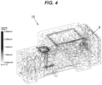
- Fig. 4 is a diagram illustrating an example of an analysis result of the airflow analysis unit 6.
- a number of arrows are shown, each representing the flow velocity and direction of each particle.
- the degree of color shading of arrow represents the flow velocity
- the direction of arrow represents the direction in which a particle flows.
- the airflow analysis unit 6 analyzes airflow from when the airflow generator 9 started operating until a predetermined analysis time (a period of time the airflow becomes close to a steady state, or a period of time which is set in advance by a worker and allows the particles to sufficiently diffuse in the indoor room) elapses, saves (stores) a result of the analysis and also displays the result on the display device 3.
- a predetermined analysis time a period of time the airflow becomes close to a steady state, or a period of time which is set in advance by a worker and allows the particles to sufficiently diffuse in the indoor room
- the analysis time may be automatically set by the airflow analysis unit 6 according to the volume of the indoor room to be subjected to analysis and the suction and blowout flow rates of the airflow generator 9.
- the behavior of the particles may be displayed by animation corresponding to the passage of time.
- the flow velocity of each particle is represented by the degree of color shading of arrow in Fig. 4
- the flow velocity may be represented by the difference in color or the length of arrow.
- the flow velocity of each particle is displayed as the airflow analysis result here, it is not limited thereto.
- a distribution of pressure in the indoor room may be displayed as the analysis result.
- the distribution calculation unit 7 calculates a distribution of at least one of airflow velocity, pressure, temperature, and humidity in the three-dimensional model 10 of the indoor room based on the analysis result of the airflow analysis unit 6.
- the distribution calculation unit 7 extracts, e.g., the flow velocity of each particle after a lapse of the analysis time from the analysis result of the airflow analysis unit 6, calculates the distribution of the extracted flow velocity, and displays the calculation result on the display device 3.
- the distribution to be calculated is not limited to the distribution of the "flow velocity of each particle after a lapse of the analysis time", and may be, e.g., a distribution of an average value of the flow velocity of each particle or a cumulative value of the flow velocity of each particle, or a distribution of pressure in the indoor room.
- the display format of the result of calculation by the distribution calculation unit 7 is not particularly limited, and it may be displayed as, e.g., a graph of flow velocity vs. frequency.
- the placement determination unit 8 determines the degree of suitability of a placement position of the airflow generator 9 based on the calculation result of the distribution calculation unit 7. In particular, based on, e.g., the flow velocity distribution calculated by the distribution calculation unit 7, the placement determination unit 8 calculates an evaluation score using a predetermined calculation condition.
- the calculation condition for the evaluation score is not particularly limited, but it is preferable that an appropriate calculation formula, etc. be set so that the score is low when there are more particles with low flow velocity and fewer particles with high flow velocity, and the score is high when there are fewer particles with low flow velocity and more particles with high flow velocity.
- the placement determination unit 8 displays the calculated determination result (e.g., the evaluation score) on the display device 3.
- the placement determination unit 8 may make a determination by comparing two conditions: a state in which doors or windows of a room are open for ventilation, and a state in which the airflow generator 9 is placed and operated with the doors or windows closed. For example, whether the evaluation score is better or worse than the ventilating state may be judged and displayed on the display device 3.
- Fig. 5 is a flowchart of an airflow simulation method in the present embodiment. All steps shown in Fig. 5 are performed by the airflow simulation terminal device 1 which is a portable terminal device.
- Step S1 an image capturing step is performed in Step S1.
- images of the indoor room to be subjected to airflow analysis are captured by the imaging device 2 such as three-dimensional camera (see Fig. 2 ).
- Step S2 a three-dimensional model creation step is performed in Step S2.
- the three-dimensional model creation unit 5 creates the three-dimensional model 10 of the indoor room based on image data of the indoor room captured by the imaging device 2 (see Fig. 3 ).
- Step S3 an airflow analysis step is performed in Step S3.
- analysis conditions are set in Step S31.
- various settings including the placement of the airflow generator 9 in the indoor three-dimensional model 10 (see Fig. 3 ) created in the three-dimensional model creation step, are made by using the input device 4.
- Step S32 airflow in the indoor room is analyzed based on the set analysis conditions.
- Step S33 the analysis result (see Fig. 4 ) is displayed on the display device 3 and the analysis result is also stored in a storage device, etc.
- Step S4 whether to calculate the distribution is determined based on, e.g., an input from the input device 4.
- the determination made in Step S4 is NO
- the process proceeds to Step S7.
- Step S5 a distribution calculation step is performed in Step S5.
- the distribution calculation unit 7 calculates a distribution of the airflow velocity (or pressure) in the three-dimensional model 10 of the indoor room based on the analysis result in the airflow analysis step and displays the distribution on the display device 3.
- Step S5 a placement determination step is performed in Step S5.
- the placement determination unit 8 determines the degree of suitability of a placement position of the airflow generator 9 (e.g., calculates an evaluation score) based on the calculation result of the distribution calculation unit 7, and displays the determination result on the display device 3. After that, the process proceeds to Step S7.
- Step S7 whether to analyze again is determined.
- Step S7 whether to analyze again is determined based on, e.g., an input from the input device 4.
- the determination made is YES.
- the process returns to Step S3.
- the determination made in Step S7 is NO, the process ends.
- the airflow simulation terminal device 1 in the present embodiment is composed of a portable terminal device that integrally includes the imaging device 2 to capture an image of an indoor room, the three-dimensional model creation unit 5 that creates the three-dimensional model 10 of the indoor room based on image data of the indoor room captured by the imaging device 2, and the airflow analysis unit 6 that analyzes airflow in the indoor room when the airflow generator 9 is placed in the three-dimensional model 10 of the indoor room created by the three-dimensional model creation unit 5.
- viruses are very light and their movement in the indoor room can be seen as airflow, it is possible to accurately simulate the behavior of viruses using the movement of the airflow. Therefore, according to the present embodiment, the behavior of viruses in the indoor room can be quickly analyzed on site.
Landscapes
- Engineering & Computer Science (AREA)
- Physics & Mathematics (AREA)
- General Engineering & Computer Science (AREA)
- Mechanical Engineering (AREA)
- Combustion & Propulsion (AREA)
- Chemical & Material Sciences (AREA)
- Theoretical Computer Science (AREA)
- Signal Processing (AREA)
- Geometry (AREA)
- General Physics & Mathematics (AREA)
- Mathematical Physics (AREA)
- Computer Hardware Design (AREA)
- Human Computer Interaction (AREA)
- Evolutionary Computation (AREA)
- Fuzzy Systems (AREA)
- Fluid Mechanics (AREA)
- Pure & Applied Mathematics (AREA)
- Mathematical Analysis (AREA)
- Mathematical Optimization (AREA)
- Structural Engineering (AREA)
- Computational Mathematics (AREA)
- Computing Systems (AREA)
- Algebra (AREA)
- Civil Engineering (AREA)
- Architecture (AREA)
- Management, Administration, Business Operations System, And Electronic Commerce (AREA)
- Air Conditioning Control Device (AREA)
- Image Generation (AREA)
Applications Claiming Priority (2)
| Application Number | Priority Date | Filing Date | Title |
|---|---|---|---|
| JP2021177220A JP7308902B2 (ja) | 2021-10-29 | 2021-10-29 | 気流シミュレーション端末装置、及び気流シミュレーション方法 |
| PCT/JP2022/037585 WO2023074315A1 (ja) | 2021-10-29 | 2022-10-07 | 気流シミュレーション端末装置、及び気流シミュレーション方法 |
Publications (2)
| Publication Number | Publication Date |
|---|---|
| EP4407247A1 true EP4407247A1 (de) | 2024-07-31 |
| EP4407247A4 EP4407247A4 (de) | 2025-10-08 |
Family
ID=86159268
Family Applications (1)
| Application Number | Title | Priority Date | Filing Date |
|---|---|---|---|
| EP22886646.3A Pending EP4407247A4 (de) | 2021-10-29 | 2022-10-07 | Luftstromsimulationsendgerätevorrichtung und luftstromsimulationsverfahren |
Country Status (5)
| Country | Link |
|---|---|
| US (1) | US20250012471A1 (de) |
| EP (1) | EP4407247A4 (de) |
| JP (1) | JP7308902B2 (de) |
| CN (1) | CN118159972A (de) |
| WO (1) | WO2023074315A1 (de) |
Family Cites Families (8)
| Publication number | Priority date | Publication date | Assignee | Title |
|---|---|---|---|---|
| US20060121421A1 (en) * | 2004-10-15 | 2006-06-08 | Spitaels James S | IT equipment simulation |
| JP5449851B2 (ja) | 2009-05-08 | 2014-03-19 | 大成建設株式会社 | 配置計画支援装置 |
| JP7121360B2 (ja) | 2017-10-25 | 2022-08-18 | 暮らしの科学研究所株式会社 | 室内環境制御システム |
| CN111742181B (zh) * | 2018-06-14 | 2023-02-28 | 松下知识产权经营株式会社 | 信息处理方法、信息处理系统以及记录介质 |
| JP7286333B2 (ja) * | 2019-02-06 | 2023-06-05 | キヤノン株式会社 | 情報処理装置、情報処理装置の制御方法およびプログラム |
| CN113795856B (zh) | 2019-08-08 | 2024-09-24 | 松下知识产权经营株式会社 | 空间提案系统以及空间提案方法 |
| CN110910503B (zh) * | 2019-10-15 | 2022-04-15 | 珠海格力电器股份有限公司 | 一种空调环境的仿真方法及装置 |
| JP2021082000A (ja) * | 2019-11-19 | 2021-05-27 | 東京電力ホールディングス株式会社 | 学習済モデルの生成方法、コンピュータプログラム、情報処理方法及び情報処理装置 |
-
2021
- 2021-10-29 JP JP2021177220A patent/JP7308902B2/ja active Active
-
2022
- 2022-10-07 EP EP22886646.3A patent/EP4407247A4/de active Pending
- 2022-10-07 US US18/703,763 patent/US20250012471A1/en active Pending
- 2022-10-07 CN CN202280072341.2A patent/CN118159972A/zh active Pending
- 2022-10-07 WO PCT/JP2022/037585 patent/WO2023074315A1/ja not_active Ceased
Also Published As
| Publication number | Publication date |
|---|---|
| CN118159972A (zh) | 2024-06-07 |
| JP7308902B2 (ja) | 2023-07-14 |
| US20250012471A1 (en) | 2025-01-09 |
| WO2023074315A1 (ja) | 2023-05-04 |
| EP4407247A4 (de) | 2025-10-08 |
| JP2023066563A (ja) | 2023-05-16 |
Similar Documents
| Publication | Publication Date | Title |
|---|---|---|
| US20220207215A1 (en) | Contaminant spread analysis | |
| Zuo et al. | Real-time or faster-than-real-time simulation of airflow in buildings | |
| JP5492522B2 (ja) | 空調制御装置および方法 | |
| US20220300686A1 (en) | Information processing device, information processing system, and information processing method | |
| US20240019152A1 (en) | Visualization system, and program | |
| Pazhoohesh et al. | Investigating thermal comfort and occupants position impacts on building sustainability using CFD and BIM | |
| EP4407247A1 (de) | Luftstromsimulationsendgerätevorrichtung und luftstromsimulationsverfahren | |
| KR20220057953A (ko) | 공기질 시뮬레이션 장치 및 방법 | |
| EP4336114A1 (de) | Klimaanlagensteuerungsvorrichtung | |
| O'Neal et al. | Modeling Fan-Powered Terminal Unit Fan/Motor Combinations Controlled by Silicon Controlled Rectifiers. | |
| KR20240071358A (ko) | 환기 가이드 장치, 애플리케이션 및 방법 | |
| Kwag et al. | Evaluation of the impact of installation environment for a condensing unit of a split-type air conditioner in a plant room of Korean apartment dwellings | |
| KR102655494B1 (ko) | 공기질 관리 장치 및 방법 | |
| Marschall et al. | Simulating natural ventilation in early stage design: combining an occupant behavior model with an airflow network approach | |
| CN208419104U (zh) | 一种房间空气质量显示及控制系统 | |
| JP2022182901A (ja) | 建築物の設計方法 | |
| JP7756315B2 (ja) | 環境推定方法、及び、プログラム | |
| CN103902032A (zh) | 显示装置、可携式装置及虚拟情境控制方法 | |
| Ogrodnik et al. | Numerical modeling of particle transport in an allergen exposure chamber | |
| JP7563115B2 (ja) | 室内環境管理支援装置および室内環境管理支援方法 | |
| CN114818047B (zh) | 一种基于三维模型的生活热水能耗模拟方法及系统 | |
| Beh | Development of Numerical Model and Design Framework for Mixed-Mode Ventilation for High Rise Buildings | |
| Besse | Visual Understanding Of Simulated Flow Field Data | |
| Svidt et al. | Visualisation of CFD results in a virtual reality environment | |
| Schwede | TOWARDS A UNIVERSAL AND INTEGRATED DIGITAL REPRESENTATION OF PHYSICAL PHENOMENA A model to investigate comfort and energy efficiency in future environments |
Legal Events
| Date | Code | Title | Description |
|---|---|---|---|
| STAA | Information on the status of an ep patent application or granted ep patent |
Free format text: STATUS: THE INTERNATIONAL PUBLICATION HAS BEEN MADE |
|
| PUAI | Public reference made under article 153(3) epc to a published international application that has entered the european phase |
Free format text: ORIGINAL CODE: 0009012 |
|
| STAA | Information on the status of an ep patent application or granted ep patent |
Free format text: STATUS: REQUEST FOR EXAMINATION WAS MADE |
|
| 17P | Request for examination filed |
Effective date: 20240426 |
|
| AK | Designated contracting states |
Kind code of ref document: A1 Designated state(s): AL AT BE BG CH CY CZ DE DK EE ES FI FR GB GR HR HU IE IS IT LI LT LU LV MC ME MK MT NL NO PL PT RO RS SE SI SK SM TR |
|
| DAV | Request for validation of the european patent (deleted) | ||
| DAX | Request for extension of the european patent (deleted) | ||
| REG | Reference to a national code |
Ref country code: DE Ref legal event code: R079 Free format text: PREVIOUS MAIN CLASS: F24F0011640000 Ipc: G06F0030280000 |
|
| A4 | Supplementary search report drawn up and despatched |
Effective date: 20250908 |
|
| RIC1 | Information provided on ipc code assigned before grant |
Ipc: G06F 30/28 20200101AFI20250902BHEP Ipc: G06F 30/13 20200101ALI20250902BHEP Ipc: F24F 11/30 20180101ALI20250902BHEP Ipc: F24F 11/52 20180101ALI20250902BHEP Ipc: F24F 11/56 20180101ALI20250902BHEP Ipc: F24F 11/63 20180101ALI20250902BHEP Ipc: F24F 11/64 20180101ALI20250902BHEP Ipc: F24F 11/74 20180101ALI20250902BHEP Ipc: F24F 11/79 20180101ALI20250902BHEP Ipc: G06F 113/08 20200101ALN20250902BHEP Ipc: F24F 110/30 20180101ALN20250902BHEP |