EP4407198B1 - Solarmodulbefestigungssystem mit sicherungsbolzen - Google Patents
Solarmodulbefestigungssystem mit sicherungsbolzen Download PDFInfo
- Publication number
- EP4407198B1 EP4407198B1 EP24151856.2A EP24151856A EP4407198B1 EP 4407198 B1 EP4407198 B1 EP 4407198B1 EP 24151856 A EP24151856 A EP 24151856A EP 4407198 B1 EP4407198 B1 EP 4407198B1
- Authority
- EP
- European Patent Office
- Prior art keywords
- head
- wall
- solar module
- retaining groove
- fastening system
- Prior art date
- Legal status (The legal status is an assumption and is not a legal conclusion. Google has not performed a legal analysis and makes no representation as to the accuracy of the status listed.)
- Active
Links
Images




Classifications
-
- F—MECHANICAL ENGINEERING; LIGHTING; HEATING; WEAPONS; BLASTING
- F24—HEATING; RANGES; VENTILATING
- F24S—SOLAR HEAT COLLECTORS; SOLAR HEAT SYSTEMS
- F24S25/00—Arrangement of stationary mountings or supports for solar heat collector modules
- F24S25/60—Fixation means, e.g. fasteners, specially adapted for supporting solar heat collector modules
- F24S25/63—Fixation means, e.g. fasteners, specially adapted for supporting solar heat collector modules for fixing modules or their peripheral frames to supporting elements
-
- F—MECHANICAL ENGINEERING; LIGHTING; HEATING; WEAPONS; BLASTING
- F16—ENGINEERING ELEMENTS AND UNITS; GENERAL MEASURES FOR PRODUCING AND MAINTAINING EFFECTIVE FUNCTIONING OF MACHINES OR INSTALLATIONS; THERMAL INSULATION IN GENERAL
- F16B—DEVICES FOR FASTENING OR SECURING CONSTRUCTIONAL ELEMENTS OR MACHINE PARTS TOGETHER, e.g. NAILS, BOLTS, CIRCLIPS, CLAMPS, CLIPS OR WEDGES; JOINTS OR JOINTING
- F16B35/00—Screw-bolts; Stay-bolts; Screw-threaded studs; Screws; Set screws
- F16B35/04—Screw-bolts; Stay-bolts; Screw-threaded studs; Screws; Set screws with specially-shaped head or shaft in order to fix the bolt on or in an object
- F16B35/06—Specially-shaped heads
-
- H—ELECTRICITY
- H02—GENERATION; CONVERSION OR DISTRIBUTION OF ELECTRIC POWER
- H02S—GENERATION OF ELECTRIC POWER BY CONVERSION OF INFRARED RADIATION, VISIBLE LIGHT OR ULTRAVIOLET LIGHT, e.g. USING PHOTOVOLTAIC [PV] MODULES
- H02S20/00—Supporting structures for PV modules
- H02S20/20—Supporting structures directly fixed to an immovable object
- H02S20/22—Supporting structures directly fixed to an immovable object specially adapted for buildings
- H02S20/23—Supporting structures directly fixed to an immovable object specially adapted for buildings specially adapted for roof structures
-
- F—MECHANICAL ENGINEERING; LIGHTING; HEATING; WEAPONS; BLASTING
- F16—ENGINEERING ELEMENTS AND UNITS; GENERAL MEASURES FOR PRODUCING AND MAINTAINING EFFECTIVE FUNCTIONING OF MACHINES OR INSTALLATIONS; THERMAL INSULATION IN GENERAL
- F16B—DEVICES FOR FASTENING OR SECURING CONSTRUCTIONAL ELEMENTS OR MACHINE PARTS TOGETHER, e.g. NAILS, BOLTS, CIRCLIPS, CLAMPS, CLIPS OR WEDGES; JOINTS OR JOINTING
- F16B5/00—Joining sheets or plates, e.g. panels, to one another or to strips or bars parallel to them
- F16B5/02—Joining sheets or plates, e.g. panels, to one another or to strips or bars parallel to them by means of fastening members using screw-thread
-
- F—MECHANICAL ENGINEERING; LIGHTING; HEATING; WEAPONS; BLASTING
- F24—HEATING; RANGES; VENTILATING
- F24S—SOLAR HEAT COLLECTORS; SOLAR HEAT SYSTEMS
- F24S25/00—Arrangement of stationary mountings or supports for solar heat collector modules
- F24S2025/01—Special support components; Methods of use
- F24S2025/018—Means for preventing movements, e.g. stops
-
- F—MECHANICAL ENGINEERING; LIGHTING; HEATING; WEAPONS; BLASTING
- F24—HEATING; RANGES; VENTILATING
- F24S—SOLAR HEAT COLLECTORS; SOLAR HEAT SYSTEMS
- F24S25/00—Arrangement of stationary mountings or supports for solar heat collector modules
- F24S25/60—Fixation means, e.g. fasteners, specially adapted for supporting solar heat collector modules
- F24S2025/6006—Fixation means, e.g. fasteners, specially adapted for supporting solar heat collector modules by using threaded elements, e.g. stud bolts
-
- Y—GENERAL TAGGING OF NEW TECHNOLOGICAL DEVELOPMENTS; GENERAL TAGGING OF CROSS-SECTIONAL TECHNOLOGIES SPANNING OVER SEVERAL SECTIONS OF THE IPC; TECHNICAL SUBJECTS COVERED BY FORMER USPC CROSS-REFERENCE ART COLLECTIONS [XRACs] AND DIGESTS
- Y02—TECHNOLOGIES OR APPLICATIONS FOR MITIGATION OR ADAPTATION AGAINST CLIMATE CHANGE
- Y02E—REDUCTION OF GREENHOUSE GAS [GHG] EMISSIONS, RELATED TO ENERGY GENERATION, TRANSMISSION OR DISTRIBUTION
- Y02E10/00—Energy generation through renewable energy sources
- Y02E10/40—Solar thermal energy, e.g. solar towers
- Y02E10/47—Mountings or tracking
Definitions
- a U-shaped retaining groove which has a groove wall extending approximately parallel to the wall, is connected to the wall via a groove base, and is open toward the passage opening.
- the retaining groove protrudes laterally from the wall 23.
- the groove wall which runs approximately parallel to the wall, serves as a later abutment for the head of the securing bolt.
- the locking bolt and the retaining groove are coordinated in terms of size, arrangement, and shape in such a way that the head of the locking bolt can be guided in a specific orientation along the groove wall, which extends relatively close to the through-hole.
- the head has at least one area whose projection relative to the shaft is less than the distance between a free edge of the groove wall and the through-hole.
- the head is non-circular, for example, angular, particularly triangular or rectangular, but an oval basic shape is also conceivable.
- a circular segment is a partial area of a circle bounded by a circular arc and a chord.
- the desired function can also be achieved by connecting the shaft of the locking bolt to the head off-center.
- a completely round basic shape could also be screwed into and out of the retaining groove.
- the head is further preferably characterized in that the depth of the head varies in the circumferential direction, with the maximum depth of the head approximately corresponding to the inside width of the retaining groove. This facilitates screwing into the retaining groove.
- the maximum depth of the head preferably exceeds the inside width of the retaining groove such that screwing the deeper portion into the retaining groove causes the head to jam in the retaining groove.
- the retaining groove and/or the head are preferably elastically deformed in the process.
- the depth of the head preferably increases counterclockwise, either continuously or in steps. Counterclockwise is particularly useful because the direction of rotation when screwing in the locking bolt corresponds to the usual tightening of a screw.
- the head can have roughness-enhancing structures on at least one outer side to increase frictional engagement in the locking position. This ensures that the locking bolt does not rotate back and loosen, even when the components move, for example due to wind.
- the outer sides can be roughened or provided with a serrated structure, for example. It is also conceivable for the outer surfaces of the head to be covered with a rough and/or elastic plastic material. The outer sides or outer surfaces are those surfaces that come into contact with the wall or an inner side of the groove wall.
- FIGS. 1 to 7 show a preferred embodiment of a solar module fastening system 20.
- This essentially has a rail 22 with a wall 23 and securing bolts 28 that can be connected to the rail 22.
- the securing bolt 26 has a head 30 connected to the shaft 28.
- the head 30 is round except for a missing circular segment. Furthermore, it can be seen that the head 30 protrudes beyond the width of the shaft 28 in cross-section and rests against the wall 23 in an initial position.
- a retaining groove 40 is formed on the wall 23, which protrudes from the wall 23 and is formed from a groove wall 32 extending substantially parallel to the wall 23 and a groove bottom 34 connecting the groove wall 32 to the wall 23.
- the Figures 5 to 7 illustrate that the head 30 is designed with varying depths or thicknesses across its circumference.
- the head has steps of varying depths, increasing counterclockwise. Alternatively, a continuous increase in depth is also possible.
- the Figures 1 to 4 illustrate that insertion of the locking bolt 26 is only possible if the head 30 is aligned such that the area in which a circular segment is missing is aligned towards the groove wall 32. Only in this way is it possible to insert the shaft 28 of the locking bolt 26 into the through-hole 24. Only when the head 30 rests with its inner side against the wall 23 can the area with greater depth be screwed into the retaining groove 40 and clamped or locked. This is also illustrated by the Figures 6 and 7 .
- the retaining groove 40 has a clear width NB which corresponds approximately to the depth of at least one region of the head 30 which can be screwed into the retaining groove 40.
Landscapes
- Engineering & Computer Science (AREA)
- General Engineering & Computer Science (AREA)
- Mechanical Engineering (AREA)
- Architecture (AREA)
- Civil Engineering (AREA)
- Structural Engineering (AREA)
- Physics & Mathematics (AREA)
- Life Sciences & Earth Sciences (AREA)
- Sustainable Development (AREA)
- Sustainable Energy (AREA)
- Thermal Sciences (AREA)
- Chemical & Material Sciences (AREA)
- Combustion & Propulsion (AREA)
- Roof Covering Using Slabs Or Stiff Sheets (AREA)
- Photovoltaic Devices (AREA)
Description
- Die Erfindung betrifft ein Solarmodulbefestigungssystem mit mindestens einer auf einem Untergrund, insbesondere an einem Dach befestigbaren Schiene zur Befestigung von Elementen einer Solaranlage, wobei die Schiene eine Wand mit einer Durchgangsöffnung aufweist, durch die ein Sicherungsbolzen einführbar ist.
- Zur Anordnung von Solaranlagen, insbesondere Photovoltaik-Modulen (PV-Modulen) auf Flachdächern werden üblicherweise Schienen verwendet, um die Photovoltaik-Module auf den Flachdächern zu positionieren und zu befestigen. Dabei ist es bekannt, Schienen in mehreren Reihen anzuordnen und in einer Reihe mehrere Schienen hintereinander. Die Schienen werden miteinander verbunden, um so eine Art Schachbrettmuster aus parallelen Schienen und dazu quer verlaufenden Verbindungsstücken bzw. Modulen zu erzeugen. Zwei beiden hintereinander angeordneten Schienen sind dabei häufig durch ein Verbindungselement bzw. eine Traufstütze miteinander verbunden. Traufstützen können aber auch an anderer Stelle im Verlauf der Schiene angeordnet sein.
- Neben Verbindungselementen und Traufstützen können und werden auch weitere Bauteile mit den Schienen verbunden. Zu diesem Zweck werden Befestigung- oder Sicherungsbolzen verwendet, die in die Durchgangsöffnung in die Wand der Schiene eingeführt werden. Üblicherweise sind die Sicherungsbolzen als Schraube ausgeführt, die dann in der Befestigung- oder Sicherungsposition verschraubt werden und so die verschiedenen Elemente verbinden und halten.
- Die Montage bzw. der Zusammenbau der Elemente ist aufgrund des Verschraubungsvorgangs aufwendig und zeitintensiv. Insbesondere besteht auch die Gefahr des Verlierens von Muttern der Sicherungsbolzen. Diese können im ungünstigsten Fall vom Dach herunterfallen, was den Montageaufwand zusätzlich erschwert und verlängert. Ein Montagesystem aus dem Stand der Technik ist in dem Dokument
DE 10 2016 111 983 A1 offenbart. - Der Erfindung liegt die Aufgabe zugrunde, eine alternative Ausführungsform eines solchen Solarmodulbefestigungssystems anzugeben. Dieses soll eine einfache und robuste Konstruktion aufweisen, kostengünstig herzustellen und insbesondere auch schnell und einfach zu montieren sein.
- Diese Aufgabe wird erfindungsgemäß durch einen Solarmodulbefestigungssystem mit den Merkmalen des Anspruchs 1 sowie durch ein Verfahren zur Befestigung mit den Merkmalen des Anspruchs 8 gelöst.
- Demnach weist das Solarmodulbefestigungssystem eine Schiene mit einer Durchgangsöffnung auf, durch die ein Sicherungsbolzen zur Verbindung oder Halterung mit weiteren Elementen eingeführt werden kann.
- Unterhalb der Durchgangöffnung ist eine U-förmige Haltenut angeordnet, die eine sich etwa parallel zur Wand erstreckende Nutwand aufweist, über einen Nutboden mit der Wand verbunden und in Richtung der Durchgangöffnung geöffnet ist. Die Haltenut steht seitlich von der Wand 23 ab. Die etwa parallel zur Wand verlaufende Nutwand dient als späteres Widerlager für den Kopf des Sicherungbolzens.
- Der erfindungsgemäße Sicherungsbolzen weist einen Schaft und einen Kopf auf, die derart ausgeführt und angeordnet sind, dass der Kopf in einer Ausgangsposition, in der der Schaft in die Durchgangöffnung bis zum Anschlag des Kopfes an der Wand eingeführt ist, ausserhalb der Haltenut angeordnet ist. In einer Sicherungsposition ist der der Sicherungsbolzen gegenüber der Ausgangsposition um eine Längsachse des Schafts verdreht und ragt bereichsweise in die Haltenut hinein.
- Wesentlich ist also, dass der Sicherungsbolzen und die Haltenut in Bezug auf Größe, Anordnung und Form derart aufeinander abgestimmt sind, dass der Kopf des Sicherungsbolzens in einer bestimmten Ausrichtung an der relativ nahe an der Durchgangsöffnung heranreichende Nutwand vorbeigeführt werden kann. Hierzu weist der Kopf zumindest einen Bereich auf, dessen Überstand gegenüber dem Schaft geringer ist, als der Abstand einer freien Kante der Nutwand zur Durchgangsöffnung.
- Ist der Sicherungsbolzen vollständig eingeführt, wird anschließend der Kopf aus der Ausgangsposition verdreht, bis der entsprechende Bereich in der Haltenut angeordnet ist.
- Zusammengefasst erfolgt die Montage folgendermaßen:
- Befestigen der Schiene auf einem Untergrund,
- Ausrichten des Sicherungsbolzens in Bezug auf die Durchgangöffnung und die Nutwand,
- Einführen des Sicherungsbolzens in die Durchgangöffnung der Wand und ggfs. in eine Öffnung in einem zu verbindenden Element,
- Vorbeiführen des Kopfes des Sicherungsbolzens an der Nutwand in eine Ausgangsposition des Sicherungsbolzens,
- Verdrehen des Sicherungsbolzens um die Längsachse des Schafts von der Ausgangsposition in eine Sicherungsposition, in der Kopf bereichsweise in die Haltenut hineinragt.
- Die Realisierung verschiedener Bereiche des Kopfs, die sich unterschiedlich weit vom Schaft weg erstrecken, kann auf unterschiedliche Art und Weise realisiert werden. In einer ersten Ausführungsvariante ist der Kopf unrund ausgeführt, beispielsweise eckig, insbesondere drei- oder rechteckig, denkbar ist aber auch eine ovale Grundform. Ein Kopf mit grundsätzlich runder Grundform, bei dem ein Kreissegment (Kreisabschnitt) fehlt, ist ebenfalls möglich. Ein Kreissegment ist eine Teilfläche einer Kreisfläche, die von einem Kreisbogen und einer Kreissehne begrenzt wird.
- Alternativ oder zusätzlich kann die gewünschte Funktion auch dadurch erreicht werden, dass der Schaft des Sicherungsbolzens außermittig mit dem Kopf verbunden ist. In diesem Fall könnte auch eine vollständige runde Grundform in die Haltenut hinein und wieder heraus gedreht werden.
- Der Kopf ist weiterhin vorzugsweise dadurch gekennzeichnet, dass die Tiefe des Kopfes in Umfangsrichtung unterschiedlich ausgeführt ist, wobei die maximale Tiefe des Kopfes etwa einer lichten Breite der Haltenut entspricht. Dadurch wird ein Eindrehen in die Haltenut erleichtert. Die maximale Tiefe des Kopfes übersteigt vorzugsweise die lichte Breite der Haltenut derart, dass ein Eindrehen des tieferen Bereichs in die Haltenut ein Verklemmen des Kopfes in der Haltenut bewirkt. Die Haltenut und/oder der Kopf wird dabei vorzugsweise elastisch verformt.
- Die Tiefe des Kopfes nimmt vorzugsweise entgegen dem Uhrzeigersinn kontinuierlich oder in Stufen zu. Entgegen dem Uhrzeigersinn ist deswegen besonders sinnvoll, weil dann die Drehrichtung beim Eindrehen des Sicherungsbolzens dem üblichen Festdrehen einer Schraube entspricht.
- Der Kopf kann an zumindest einer Aussenseite rauigkeitserhöhende Strukturen zur Erhöhung eines Reibschlusses in der Sicherungsposition aufweisen. Dadurch wird gewährleistet, dass sich auch bei Bewegung der Bauteile, beispielsweise aufgrund von Wind, der Sicherungsbolzen nicht zurückdreht und löst. Die Außenseiten können dazu beispielsweise aufgeraut oder beispielsweise mit einer Zackenstruktur versehen sein. Denkbar ist auch, dass die Außenflächen des Kopfes mit einem rauen und/oder elastischen Kunststoffmaterial versehen sind. Die Außenseiten oder Außenflächen sind diejenigen Flächen, die mit der Wand oder einer Innenseite der Nutwand in Kontakt kommen.
- Die Erfindung wird anhand der nachfolgenden Figuren näher erläutert. Diese stellen lediglich ein bevorzugtes Ausführungsbeispiel dar und sollen nicht einschränkend zu verstehen sein. Die Abmessungen sind dabei nicht maßstäblich, Dimensionen und Abmessungen können auch geändert abweichen. Es zeigen:
- Fig. 1:
- ein Solarmodulbefestigungssystems mit einer Schiene und einem Sicherungsbolzen
- Fig. 2:
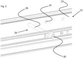
- das Solarmodulbefestigungssystems mit eigeführtem Sicherungsbolzen in Ausgangsposition,
- Fig. 3:
- das Solarmodulbefestigungssystems mit eigeführtem Sicherungsbolzen in einer Zwischenposition,
- Fig. 4:
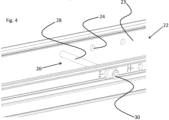
- das Solarmodulbefestigungssystems mit eigeführtem Sicherungsbolzen in einer Sicherungsposition,
- Fig. 5:
- das Solarmodulbefestigungssystems mit eigeführtem Sicherungsbolzen in einer Sicherungsposition von oben,
- Fig. 6:
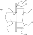
- das Solarmodulbefestigungssystems mit eigeführtem Sicherungsbolzen in Ausgangsposition in vereinfachter Schnittdarstellung,
- Fig. 7:
- das Solarmodulbefestigungssystems mit eigeführtem Sicherungsbolzen in Sicherungsposition in vereinfachter Schnittdarstellung.
- Die
Figuren 1 bis 7 zeigen eine bevorzugte Ausführungsvariante eines Solarmodulbefestigungssystems 20. Dieses weist im Wesentlichen eine Schiene 22 mit einer Wand 23 und mit der Schiene 22 verbindbaren Sicherungsbolzen 28 auf. - In die Wand 23 der Schiene 22 sind im gezeigten Ausführungsbeispiel mehrere Durchgangsöffnungen 24 eingebracht, in die ein Schaft 28 des Sicherungsbolzen 26 einführbar ist.
- Der Sicherungsbolzen 26 weist einen Kopf 30 auf, der mit dem Schaft 28 verbunden ist. Der Kopf 30 ist mit Ausnahme eines fehlenden Kreissegments rund ausgeführt. Weiterhin ist erkennbar, dass der Kopf 30 im Querschnitt über die Breite des Schafts 28 vorsteht und in einer Ausgangsposition an der Wand 23 zur Anlage kommt.
- An die Wand 23 ist eine Haltenut 40 angeformt, die von der Wand 23 absteht und aus einer sich im Wesentlichen parallel zur Wand 23 erstreckenden Nutwand 32 und einem die Nutwand 32 mit der Wand 23 verbindenden Nutboden 34 gebildet ist.
- Insbesondere die
Figuren 5 bis 7 verdeutlichen, dass der Kopf 30 in seiner Tiefe über seinen Umfang unterschiedlich tief oder dick ausgeführt ist. Im gezeigten Ausführungsbeispiel weist der Kopf entsprechend Stufen unterschiedlicher Tiefe auf, deren Tiefe gegen den Uhrzeigersinn zunimmt. Alternativ ist auch eine kontinuierliche Zunahme der Tiefe möglich. - Die
Figuren 1 bis 4 verdeutlichen, dass ein Einführen des Sicherungbolzens 26 nur dann möglich ist, wenn der Kopf 30 derart ausgerichtet ist, dass derjenige Bereich, in dem ein Kreissegment fehlt, in Richtung Nutwand 32 ausgerichtet ist. Nur so ist es möglich, den Schaft 28 des Sicherungsbolzens 26 in die Durchgangsöffnung 24 einzuführen. Erst wenn der Kopf 30 mit seiner Innenseite an der Wand 23 anliegt, kann der Bereich mit größerer Tiefe in die Haltenut 40 eingedreht und verspannt bzw. verklemmt werden. Dies verdeutlichen auch dieFiguren 6 und7 . - Die Haltenut 40 weist eine lichte Breite NB auf, die etwa der Tiefe zumindest eines in die Haltenut 40 eindrehbaren Bereichs des Kopfes 30 entspricht.
Claims (8)
- Solarmodulbefestigungssystem (20) mit mindestens einer auf einem Untergrund, insbesondere an einem Dach befestigbaren Schiene (22) zur Befestigung von Elementen einer Solaranlage, wobei die Schiene (22) eine Wand (23) mit einer Durchgangsöffnung (24) aufweist, durch die ein Sicherungsbolzen (26) einführbar ist,
dadurch gekennzeichnet, dass- unterhalb der Durchgangöffnung (24) eine U-förmige Haltenut (40) angeordnet ist, die- eine sich etwa parallel zur Wand (23) erstreckende Nutwand (32) aufweist, die über einen Nutboden (34) mit der Wand (23) verbunden ist,- in Richtung der Durchgangöffnung (24) geöffnet ist,- der Sicherungsbolzen (26) einen Schaft (28) und einen Kopf (30) aufweist, die derart ausgeführt und angeordnet sind, dass- der Kopf (30) in einer Ausgangsposition, in der der Schaft (28) in die Durchgangöffnung (24) bis zum Anschlag des Kopfes (30) an der Wand (23) eingeführt ist, ausserhalb der Haltenut (40) angeordnet ist,- der Kopf (30) in einer zweiten Sicherungsposition, in der der Sicherungsbolzen (26) gegenüber der Ausgangsposition um eine Längsachse des Schafts verdreht ist und bereichsweise in die Haltenut (40) hineinragt. - Solarmodulbefestigungssystem (20) nach Anspruch 1, dadurch gekennzeichnet, dass der Schaft (28) des Sicherungsbolzens außermittig mit dem Kopf (30) verbunden ist.
- Solarmodulbefestigungssystem (20) nach Anspruch 1, dadurch gekennzeichnet, dass der Kopf (30) des Sicherungsbolzens (26) unrund ausgeführt ist.
- Solarmodulbefestigungssystem (20) nach Anspruch 1, dadurch gekennzeichnet, dass die Tiefe des Kopfes (30) des Sicherungsbolzens (26) in Umfangsrichtung unterschiedlich ausgeführt ist, wobei die maximale Tiefe des Kopfes (30) etwa einer lichten Breite (NB) der Haltenut (40) entspricht.
- Solarmodulbefestigungssystem (20) nach Anspruch 1, dadurch gekennzeichnet, dass die maximale Tiefe die lichte Breite (NB) der Haltenut (40) derart übersteigt, dass ein Eindrehen des tieferen Bereichs in die Haltenut (40) ein Verklemmen des Kopfes (30) in der Haltenut (40) bewirkt.
- Solarmodulbefestigungssystem (20) nach Anspruch 4 oder 5, dadurch gekennzeichnet, dass die Tiefe des Kopfes (30) in Umfangsrichtung, vorzugsweise entgegen dem Uhrzeigersinn kontinuierlich zunimmt.
- Solarmodulbefestigungssystem (20) nach einem der Ansprüche 1 bis 6, dadurch gekennzeichnet, dass der Kopf (30) an zumindest einer Aussenseite rauigkeitserhöhende Strukturen zur Erhöhung eines Reibschlusses in der Sicherungsposition aufweist.
- Verfahren zur Befestigung eines Elementes an einer Schiene (22) eines Solarmodulbefestigungssystem (20) nach einem der Ansprüche 1 bis 7, gekennzeichnet durch die nachfolgenden Verfahrensschritte- Befestigen der Schiene (22) auf einem Untergrund,- Ausrichten des Sicherungsbolzens (26) in Bezug auf die Durchgangöffnung (24) und die Nutwand (32),- Einführen des Sicherungsbolzens (26) in die Durchgangöffnung (24) der Wand (23),- Vorbeiführen des Kopfes (30) des Sicherungsbolzens (26) an der Nutwand (32) in eine Ausgangsposition des Sicherungsbolzens (26),- Verdrehen des Sicherungsbolzens (26) um die Längsachse des Schafts (28) von der Ausgangsposition in eine Sicherungsposition, in der der Kopf (30) bereichsweise in die Haltenut (40) hineinragt.
Priority Applications (2)
| Application Number | Priority Date | Filing Date | Title |
|---|---|---|---|
| HRP20251195TT HRP20251195T1 (hr) | 2023-01-27 | 2024-01-15 | Sustav za učvršćivanje solarnih modula sa sigurnosnim vijkom |
| RS20250972A RS67324B1 (sr) | 2023-01-27 | 2024-01-15 | Sistem za pričvršćivanje solarnih modula sa pričvrsnim vijkom |
Applications Claiming Priority (1)
| Application Number | Priority Date | Filing Date | Title |
|---|---|---|---|
| DE102023102089.7A DE102023102089B3 (de) | 2023-01-27 | 2023-01-27 | Solarmodulbefestigungssystem mit Sicherungsbolzen |
Publications (3)
| Publication Number | Publication Date |
|---|---|
| EP4407198A1 EP4407198A1 (de) | 2024-07-31 |
| EP4407198C0 EP4407198C0 (de) | 2025-07-02 |
| EP4407198B1 true EP4407198B1 (de) | 2025-07-02 |
Family
ID=89620141
Family Applications (1)
| Application Number | Title | Priority Date | Filing Date |
|---|---|---|---|
| EP24151856.2A Active EP4407198B1 (de) | 2023-01-27 | 2024-01-15 | Solarmodulbefestigungssystem mit sicherungsbolzen |
Country Status (7)
| Country | Link |
|---|---|
| EP (1) | EP4407198B1 (de) |
| DE (1) | DE102023102089B3 (de) |
| ES (1) | ES3044035T3 (de) |
| HR (1) | HRP20251195T1 (de) |
| HU (1) | HUE073466T2 (de) |
| PL (1) | PL4407198T3 (de) |
| RS (1) | RS67324B1 (de) |
Family Cites Families (3)
| Publication number | Priority date | Publication date | Assignee | Title |
|---|---|---|---|---|
| DE202012001078U1 (de) | 2012-02-03 | 2013-05-06 | Ideematec Deutschland Gmbh | Befestigungssystem für Solarmodule |
| DE102016111983B4 (de) * | 2016-06-30 | 2024-01-25 | Airbus Operations Gmbh | Modulares Schienensystem |
| FR3073264B3 (fr) | 2017-11-09 | 2020-01-31 | Bollhoff Otalu Sa | Ecrou, profile muni d'un tel ecrou et procede de montage de l'ecrou sur le profile |
-
2023
- 2023-01-27 DE DE102023102089.7A patent/DE102023102089B3/de active Active
-
2024
- 2024-01-15 PL PL24151856.2T patent/PL4407198T3/pl unknown
- 2024-01-15 ES ES24151856T patent/ES3044035T3/es active Active
- 2024-01-15 HR HRP20251195TT patent/HRP20251195T1/hr unknown
- 2024-01-15 HU HUE24151856A patent/HUE073466T2/hu unknown
- 2024-01-15 RS RS20250972A patent/RS67324B1/sr unknown
- 2024-01-15 EP EP24151856.2A patent/EP4407198B1/de active Active
Also Published As
| Publication number | Publication date |
|---|---|
| DE102023102089B3 (de) | 2024-03-14 |
| ES3044035T3 (en) | 2025-11-26 |
| EP4407198C0 (de) | 2025-07-02 |
| HUE073466T2 (hu) | 2026-01-28 |
| EP4407198A1 (de) | 2024-07-31 |
| HRP20251195T1 (hr) | 2025-12-05 |
| RS67324B1 (sr) | 2025-11-28 |
| PL4407198T3 (pl) | 2026-02-02 |
Similar Documents
| Publication | Publication Date | Title |
|---|---|---|
| DE10357844B4 (de) | Befestigungssystem | |
| DE102010028653A1 (de) | System zum Befestigen eines Anbauteiles an Montagegeschienen | |
| EP2253902B1 (de) | Bauteilesatz für die Montage von Solarmodulen auf einem Dach | |
| EP2092202A1 (de) | Käfigmutter | |
| EP4365384B1 (de) | Befestigungsvorrichtung, montageeinheit und verfahren zur montage einer hammerkopfschraube an einer ankerschiene | |
| EP2372269A2 (de) | Verbindungsvorrichtung und Profilanordnung | |
| WO2020084143A1 (de) | Verkleidungssystem für eine wand, anordnung des verkleidungssystems und verfahren zur montage des verkleidungssystems | |
| DE102020110550B4 (de) | Modulklemme, Verfahren zur Befestigung von Solarmodulen, Verbindungsanordnung zur Befestigung eines Solarmoduls und Anordnung mit Verbindungsanordnung und Solarmodul | |
| EP3271594B1 (de) | Verbindungsanordnung zum ausgleich fertigungs- und/oder montagebedingter toleranzen zwischen bauteilen | |
| DE20204146U1 (de) | Vorrichtung zur Montage eines Kollektors und Befestigungselement | |
| DE102023102089B3 (de) | Solarmodulbefestigungssystem mit Sicherungsbolzen | |
| DE202007019242U1 (de) | Anordnung zur Lagesicherung einer Befestigungsschraube an einer Profilschiene sowie Bauteil hierfür | |
| DE202018107015U1 (de) | Vorrichtung zum Befestigen von Dachrinnen | |
| EP1775482A1 (de) | Schnellbefestigungselement | |
| DE202012001078U1 (de) | Befestigungssystem für Solarmodule | |
| DE102010037679B4 (de) | Handbetätigtes Werkzeug mit einem Außen-Mehrkant und einem weiteren Mehrkant | |
| DE202007003061U1 (de) | Montageverbinder und Montageeinheit | |
| EP3529431B1 (de) | Tragstruktur für fassadenelemente | |
| DE2636654C2 (de) | Befestigung einer Mutter an einem Bauteil und geeignete Mutter | |
| EP4074561B1 (de) | Halterung für ein esc-modul | |
| EP2221490B1 (de) | Einteiliges Befestigungselement zur Anordnung eines Stangenelementes an einer Montageschiene | |
| DE102020112194B4 (de) | Elektrofahrzeug mit Längsschwellern und in diesen gelagerter Unterbodenbatterie | |
| EP0866231B1 (de) | Vorgefertigte Befestigungsvorrichtung | |
| AT507842A1 (de) | Verbindungselement zur fluchtenden verbindung benachbarter gittermatten und damit gebauter zaun | |
| DE20112823U1 (de) | Befestigungsvorrichtung |
Legal Events
| Date | Code | Title | Description |
|---|---|---|---|
| REG | Reference to a national code |
Ref country code: HR Ref legal event code: TUEP Ref document number: P20251195T Country of ref document: HR |
|
| PUAI | Public reference made under article 153(3) epc to a published international application that has entered the european phase |
Free format text: ORIGINAL CODE: 0009012 |
|
| STAA | Information on the status of an ep patent application or granted ep patent |
Free format text: STATUS: THE APPLICATION HAS BEEN PUBLISHED |
|
| AK | Designated contracting states |
Kind code of ref document: A1 Designated state(s): AL AT BE BG CH CY CZ DE DK EE ES FI FR GB GR HR HU IE IS IT LI LT LU LV MC ME MK MT NL NO PL PT RO RS SE SI SK SM TR |
|
| STAA | Information on the status of an ep patent application or granted ep patent |
Free format text: STATUS: REQUEST FOR EXAMINATION WAS MADE |
|
| 17P | Request for examination filed |
Effective date: 20240805 |
|
| RBV | Designated contracting states (corrected) |
Designated state(s): AL AT BE BG CH CY CZ DE DK EE ES FI FR GB GR HR HU IE IS IT LI LT LU LV MC ME MK MT NL NO PL PT RO RS SE SI SK SM TR |
|
| GRAP | Despatch of communication of intention to grant a patent |
Free format text: ORIGINAL CODE: EPIDOSNIGR1 |
|
| STAA | Information on the status of an ep patent application or granted ep patent |
Free format text: STATUS: GRANT OF PATENT IS INTENDED |
|
| INTG | Intention to grant announced |
Effective date: 20250127 |
|
| GRAS | Grant fee paid |
Free format text: ORIGINAL CODE: EPIDOSNIGR3 |
|
| GRAA | (expected) grant |
Free format text: ORIGINAL CODE: 0009210 |
|
| STAA | Information on the status of an ep patent application or granted ep patent |
Free format text: STATUS: THE PATENT HAS BEEN GRANTED |
|
| AK | Designated contracting states |
Kind code of ref document: B1 Designated state(s): AL AT BE BG CH CY CZ DE DK EE ES FI FR GB GR HR HU IE IS IT LI LT LU LV MC ME MK MT NL NO PL PT RO RS SE SI SK SM TR |
|
| REG | Reference to a national code |
Ref country code: GB Ref legal event code: FG4D Free format text: NOT ENGLISH |
|
| REG | Reference to a national code |
Ref country code: CH Ref legal event code: EP |
|
| REG | Reference to a national code |
Ref country code: DE Ref legal event code: R096 Ref document number: 502024000086 Country of ref document: DE |
|
| REG | Reference to a national code |
Ref country code: IE Ref legal event code: FG4D Free format text: LANGUAGE OF EP DOCUMENT: GERMAN |
|
| U01 | Request for unitary effect filed |
Effective date: 20250703 |
|
| U07 | Unitary effect registered |
Designated state(s): AT BE BG DE DK EE FI FR IT LT LU LV MT NL PT RO SE SI Effective date: 20250710 |
|
| REG | Reference to a national code |
Ref country code: CH Ref legal event code: R17 Free format text: ST27 STATUS EVENT CODE: U-0-0-R10-R17 (AS PROVIDED BY THE NATIONAL OFFICE) Effective date: 20251024 |
|
| REG | Reference to a national code |
Ref country code: ES Ref legal event code: FG2A Ref document number: 3044035 Country of ref document: ES Kind code of ref document: T3 Effective date: 20251126 Ref country code: SK Ref legal event code: T3 Ref document number: E 47184 Country of ref document: SK |
|
| REG | Reference to a national code |
Ref country code: HR Ref legal event code: T1PR Ref document number: P20251195 Country of ref document: HR |
|
| REG | Reference to a national code |
Ref country code: GR Ref legal event code: EP Ref document number: 20250401983 Country of ref document: GR Effective date: 20251112 |
|
| PG25 | Lapsed in a contracting state [announced via postgrant information from national office to epo] |
Ref country code: IS Free format text: LAPSE BECAUSE OF FAILURE TO SUBMIT A TRANSLATION OF THE DESCRIPTION OR TO PAY THE FEE WITHIN THE PRESCRIBED TIME-LIMIT Effective date: 20251102 |
|
| REG | Reference to a national code |
Ref country code: HU Ref legal event code: AG4A Ref document number: E073466 Country of ref document: HU |
|
| REG | Reference to a national code |
Ref country code: HR Ref legal event code: ODRP Ref document number: P20251195 Country of ref document: HR Payment date: 20260112 Year of fee payment: 3 |
|
| PGFP | Annual fee paid to national office [announced via postgrant information from national office to epo] |
Ref country code: HU Payment date: 20260114 Year of fee payment: 3 |
|
| U20 | Renewal fee for the european patent with unitary effect paid |
Year of fee payment: 3 Effective date: 20260128 |
|
| PG25 | Lapsed in a contracting state [announced via postgrant information from national office to epo] |
Ref country code: SM Free format text: LAPSE BECAUSE OF FAILURE TO SUBMIT A TRANSLATION OF THE DESCRIPTION OR TO PAY THE FEE WITHIN THE PRESCRIBED TIME-LIMIT Effective date: 20250702 |
|
| PGFP | Annual fee paid to national office [announced via postgrant information from national office to epo] |
Ref country code: ME Payment date: 20260109 Year of fee payment: 3 |
|
| PGFP | Annual fee paid to national office [announced via postgrant information from national office to epo] |
Ref country code: ES Payment date: 20260217 Year of fee payment: 3 |
|
| PGFP | Annual fee paid to national office [announced via postgrant information from national office to epo] |
Ref country code: NO Payment date: 20260120 Year of fee payment: 3 Ref country code: IE Payment date: 20260121 Year of fee payment: 3 |
|
| PGFP | Annual fee paid to national office [announced via postgrant information from national office to epo] |
Ref country code: HR Payment date: 20260112 Year of fee payment: 3 |
|
| PGFP | Annual fee paid to national office [announced via postgrant information from national office to epo] |
Ref country code: RS Payment date: 20260112 Year of fee payment: 3 |
|
| PGFP | Annual fee paid to national office [announced via postgrant information from national office to epo] |
Ref country code: CZ Payment date: 20260102 Year of fee payment: 3 |
|
| PGFP | Annual fee paid to national office [announced via postgrant information from national office to epo] |
Ref country code: GR Payment date: 20260119 Year of fee payment: 3 Ref country code: PL Payment date: 20260113 Year of fee payment: 3 |
|
| PGFP | Annual fee paid to national office [announced via postgrant information from national office to epo] |
Ref country code: SK Payment date: 20260107 Year of fee payment: 3 |
|
| RAP4 | Party data changed (patent owner data changed or rights of a patent transferred) |
Owner name: RENUSOL EUROPE GMBH |
|
| U1H | Name or address of the proprietor changed after the registration of the unitary effect |
Owner name: RENUSOL EUROPE GMBH; DE |
|
| PLBE | No opposition filed within time limit |
Free format text: ORIGINAL CODE: 0009261 |
|
| STAA | Information on the status of an ep patent application or granted ep patent |
Free format text: STATUS: NO OPPOSITION FILED WITHIN TIME LIMIT |
|
| PGFP | Annual fee paid to national office [announced via postgrant information from national office to epo] |
Ref country code: MK Payment date: 20260105 Year of fee payment: 3 |