EP4407101A1 - Verfahren zur berechnung des ruhewinkels von in einem eimer gehaltenem bodenaushub, system zur berechnung des ruhewinkels von in einem eimer gehaltenem bodenaushub und lademaschine - Google Patents
Verfahren zur berechnung des ruhewinkels von in einem eimer gehaltenem bodenaushub, system zur berechnung des ruhewinkels von in einem eimer gehaltenem bodenaushub und lademaschine Download PDFInfo
- Publication number
- EP4407101A1 EP4407101A1 EP22907402.6A EP22907402A EP4407101A1 EP 4407101 A1 EP4407101 A1 EP 4407101A1 EP 22907402 A EP22907402 A EP 22907402A EP 4407101 A1 EP4407101 A1 EP 4407101A1
- Authority
- EP
- European Patent Office
- Prior art keywords
- bucket
- angle
- excavated object
- repose
- end portion
- Prior art date
- Legal status (The legal status is an assumption and is not a legal conclusion. Google has not performed a legal analysis and makes no representation as to the accuracy of the status listed.)
- Pending
Links
Images





Classifications
-
- E—FIXED CONSTRUCTIONS
- E02—HYDRAULIC ENGINEERING; FOUNDATIONS; SOIL SHIFTING
- E02F—DREDGING; SOIL-SHIFTING
- E02F9/00—Component parts of dredgers or soil-shifting machines, not restricted to one of the kinds covered by groups E02F3/00 - E02F7/00
- E02F9/26—Indicating devices
- E02F9/264—Sensors and their calibration for indicating the position of the work tool
- E02F9/265—Sensors and their calibration for indicating the position of the work tool with follow-up actions (e.g. control signals sent to actuate the work tool)
-
- E—FIXED CONSTRUCTIONS
- E02—HYDRAULIC ENGINEERING; FOUNDATIONS; SOIL SHIFTING
- E02F—DREDGING; SOIL-SHIFTING
- E02F3/00—Dredgers; Soil-shifting machines
- E02F3/04—Dredgers; Soil-shifting machines mechanically-driven
- E02F3/28—Dredgers; Soil-shifting machines mechanically-driven with digging tools mounted on a dipper- or bucket-arm, i.e. there is either one arm or a pair of arms, e.g. dippers, buckets
- E02F3/36—Component parts
- E02F3/42—Drives for dippers, buckets, dipper-arms or bucket-arms
- E02F3/43—Control of dipper or bucket position; Control of sequence of drive operations
- E02F3/431—Control of dipper or bucket position; Control of sequence of drive operations for bucket-arms, front-end loaders, dumpers or the like
-
- E—FIXED CONSTRUCTIONS
- E02—HYDRAULIC ENGINEERING; FOUNDATIONS; SOIL SHIFTING
- E02F—DREDGING; SOIL-SHIFTING
- E02F3/00—Dredgers; Soil-shifting machines
- E02F3/04—Dredgers; Soil-shifting machines mechanically-driven
- E02F3/28—Dredgers; Soil-shifting machines mechanically-driven with digging tools mounted on a dipper- or bucket-arm, i.e. there is either one arm or a pair of arms, e.g. dippers, buckets
- E02F3/36—Component parts
- E02F3/42—Drives for dippers, buckets, dipper-arms or bucket-arms
- E02F3/43—Control of dipper or bucket position; Control of sequence of drive operations
- E02F3/435—Control of dipper or bucket position; Control of sequence of drive operations for dipper-arms, backhoes or the like
-
- E—FIXED CONSTRUCTIONS
- E02—HYDRAULIC ENGINEERING; FOUNDATIONS; SOIL SHIFTING
- E02F—DREDGING; SOIL-SHIFTING
- E02F9/00—Component parts of dredgers or soil-shifting machines, not restricted to one of the kinds covered by groups E02F3/00 - E02F7/00
- E02F9/26—Indicating devices
- E02F9/264—Sensors and their calibration for indicating the position of the work tool
Definitions
- the present disclosure relates to a method for calculating an angle of repose of an excavated object held by a bucket, a system for calculating an angle of repose of an excavated object held by a bucket, and a loading machine.
- Patent Literature 1 In a technical field related to a loading machine including working equipment, a loading machine capable of obtaining the weight of a cargo material to be transferred as disclosed in Patent Literature 1 is known.
- Patent Literature 1 JP 2002-195870 A
- the loading machine adjusts, when an excavated object excavated by working equipment is loaded onto a haul vehicle, the excavated object to an appropriate weight that is optimal for the haul vehicle.
- the weight of the excavated object held by the working equipment can be predicted before excavation by using an angle of repose. Therefore, it is desirable to easily calculate the angle of repose.
- An object of the present disclosure is to easily calculate an angle of repose.
- a method for calculating an angle of repose of an excavated object held by a bucket comprises: calculating a bucket angle indicating an angle of the bucket with respect to a horizontal plane in a state where an inclination of a surface of the excavated object held by the bucket is maintained; measuring a weight of the excavated object; and calculating the angle of repose of the excavated object from shape data of the bucket, the bucket angle, and data of the excavated object including the measured weight.
- a system for calculating an angle of repose of an excavated object held by a bucket comprises: a processor, wherein the processor calculates a bucket angle indicating an angle of the bucket with respect to a horizontal plane in a state where an inclination of a surface of the excavated object held by the bucket is maintained, measures a weight of the excavated object, and calculates the angle of repose of the excavated object from shape data of the bucket, the bucket angle, and data of the excavated object including the measured weight.
- a loading machine comprises: a bucket; and a processor, wherein the processor calculates a bucket angle indicating an angle of the bucket with respect to a horizontal plane in a state where an inclination of a surface of an excavated object held by the bucket is maintained, measures a weight of the excavated object, and calculates an angle of repose of the excavated object from shape data of the bucket, the bucket angle, and data of the excavated object including the measured weight.
- a local coordinate system is set for a loading machine 1, and a positional relationship of each unit will be described using the local coordinate system.
- a first axis along a left-right direction which is a vehicle width direction of the loading machine 1 is defined as an X axis
- a second axis along a front-rear direction of the loading machine 1 is defined as a Y axis
- a third axis along a top-bottom direction of the loading machine 1 is defined as a Z axis.
- the X axis and the Y axis are orthogonal to each other.
- the Y axis and the Z axis are orthogonal to each other.
- a +X direction is a right direction, and a -X direction is a left direction.
- a +Y direction is a front direction, and a -Y direction is a rear direction.
- a +Z direction is a top direction, and a -Z direction is a bottom direction.
- FIG. 1 is a side view illustrating the loading machine 1 according to an embodiment.
- the loading machine 1 according to the embodiment is, for example, a wheel loader.
- the loading machine 1 is referred to as a wheel loader 1 as appropriate.
- the wheel loader 1 includes a vehicle body 2, a cab 4, wheels 5, and working equipment 6.
- the vehicle body 2 supports the working equipment 6.
- the cab 4 is supported by the vehicle body 2. In the embodiment, the cab 4 is disposed in an upper portion of the vehicle body 2.
- a working equipment operation device 24 described below is disposed inside the cab 4.
- the wheels 5 support the vehicle body 2.
- the wheels 5 include front wheels 5F and rear wheels 5R.
- FIG. 1 illustrates only the left front wheel 5F and the left rear wheel 5R.
- the front wheel 5F is rotatable about a rotation axis CXf.
- the rear wheel 5R is rotatable about a rotation axis CXr.
- the rotation axis CXf of the front wheel 5F and the rotation axis CXr of the rear wheel 5R are parallel to each other.
- the X axis is parallel to the rotation axis CXf of the front wheel 5F.
- the Z axis is orthogonal to a tread of the front wheel 5F in contact with a ground surface 200.
- the working equipment 6 performs a predetermined work.
- the working equipment 6 is supported by the vehicle body 2.
- the working equipment 6 is connected to the vehicle body 2.
- the working equipment 6 includes a boom 12, a bucket 13, a bell crank 14, a bucket link 15, a lift cylinder 18, and a bucket cylinder 19.
- a proximal end portion of the boom 12 is pivotably connected to the vehicle body 2.
- the boom 12 pivots about a pivot axis AXa with respect to the vehicle body 2.
- a bracket 16 is fixed to a middle portion of the boom 12.
- a proximal end portion of the bucket 13 is pivotably connected to a distal end portion of the boom 12.
- the bucket 13 pivots about a pivot axis AXb with respect to the boom 12.
- the bucket 13 is disposed in front of the front wheel 5F.
- a bracket 17 is fixed to a part of the bucket 13.
- a middle portion of the bell crank 14 is pivotably connected to the bracket 16.
- the bell crank 14 pivots about a pivot axis AXc with respect to the bracket 16.
- a lower end portion of the bell crank 14 is pivotably connected to a proximal end portion of the bucket link 15.
- a distal end portion of the bucket link 15 is pivotably connected to the bracket 17.
- the bucket link 15 pivots about a pivot axis AXd with respect to the bracket 17.
- the bell crank 14 is connected to the bucket 13 via the bucket link 15.
- the lift cylinder 18 operates the boom 12.
- a proximal end portion of the lift cylinder 18 is connected to the vehicle body 2.
- a distal end portion of the lift cylinder 18 is connected to the boom 12.
- the boom 12 pivots about a pivot axis AXe with respect to the lift cylinder 18.
- the bucket cylinder 19 operates the bucket 13.
- a proximal end portion of the bucket cylinder 19 is connected to the vehicle body 2.
- a distal end portion of the bucket cylinder 19 is connected to an upper end portion of the bell crank 14.
- the bell crank 14 pivots about a pivot axis AXf with respect to the bucket cylinder 19.
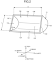
- FIG. 2 is a perspective view illustrating the bucket 13 according to the embodiment.
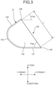
- FIG. 3 is a side view schematically illustrating the bucket 13 according to the embodiment.
- the bucket 13 is a work member that excavates an excavation target.
- the bucket 13 holds the excavated excavation target.
- the bucket 13 includes a bottom plate portion 131, a back plate portion 132, an upper plate portion 133, a right plate portion 134, and a left plate portion 135.
- a blade end portion 13A is provided at a distal end portion of the bottom plate portion 131.
- a blade edge or a blade is attached to the blade end portion 13A.
- a distal end portion of the upper plate portion 133 is an upper end portion 13B.
- a distal end portion of the right plate portion 134 is a right end portion 13C.
- a distal end portion of the left plate portion 135 is a left end portion 13D.
- the blade end portion 13A extends in the left-right direction.
- the upper end portion 13B extends in the left-right direction.
- the right end portion 13C extends in the top-bottom direction or the front-rear direction.
- the left end portion 13D extends in the top-bottom direction or the front-rear direction.
- the blade end portion 13A and the upper end portion 13B are parallel to each other.
- the right end portion 13C and the left end portion 13D are parallel to each other.
- An opening portion 136 of the bucket 13 is defined between the blade end portion 13A, the upper end portion 13B, the right end portion 13C, and the left end portion 13D.
- the opening portion 136 of the bucket 13 is defined by the blade end portion 13A, the upper end portion 13B, the right end portion 13C, and the left end portion 13D.
- a dimension of the opening portion 136 on a YZ plane that is, a dimension of a straight line connecting the blade end portion 13A and the upper end portion 13B on the YZ plane is defined as a length L.
- the dimension of the opening portion 136 in the left-right direction is defined as a width H.
- a cross-sectional area of the bucket 13 on the YZ plane is Abk.
- An angle formed by an inner surface of the bottom plate portion 131 and the straight line connecting the blade end portion 13A and the upper end portion 13B on the YZ plane is defined as a blade side opening angle ⁇ ap.
- An angle formed by the inner surface of the bottom plate portion 131 and an inner surface of the upper plate portion 133 on the YZ plane is defined as an upper side opening angle ⁇ sp.
- FIG. 4 is a diagram for describing an operation of the working equipment 6 according to the embodiment.
- the working equipment 6 is front-loading type working equipment in which the opening portion 136 of the bucket 13 faces forward in an excavation work.
- the lift cylinder 18 extends and contracts, the boom 12 performs a raising operation or a lowering operation.
- the bucket cylinder 19 extends and contracts, the bucket 13 performs a tilting operation or a dumping operation.
- the raising operation of the boom 12 is an operation in which the boom 12 pivots about the pivot axis AXa in such a way that the distal end portion of the boom 12 is separated from the ground surface 200.
- the boom 12 when the lift cylinder 18 extends, the boom 12 performs the raising operation.
- the lowering operation of the boom 12 is an operation in which the boom 12 pivots about the pivot axis AXa in such a way that the distal end portion of the boom 12 approaches the ground surface 200.
- the boom 12 when the lift cylinder 18 contracts, the boom 12 performs the lowering operation.
- the tilting operation of the bucket 13 is an operation in which the bucket 13 pivots about the pivot axis AXb in such a way that the blade end portion 13A is separated from the ground surface 200 in a state where the opening portion 136 of the bucket 13 faces upward.
- the bell crank 14 pivots in such a way that the upper end portion of the bell crank 14 moves forward and the lower end portion of the bell crank 14 moves rearward.
- the bucket 13 is pulled rearward by the bucket link 15 and performs the tilting operation.
- the dumping operation of the bucket 13 is an operation in which the bucket 13 pivots about the pivot axis AXb in such a way that the blade end portion 13A approaches the ground surface 200 in a state where the opening portion 136 of the bucket 13 faces downward.
- the bell crank 14 pivots in such a way that the upper end portion of the bell crank 14 moves rearward and the lower end portion of the bell crank 14 moves forward.
- the bucket 13 is pushed forward by the bucket link 15 and performs the dumping operation.
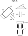
- FIG. 5 is a diagram for describing an operation of the wheel loader 1 according to the embodiment.
- the wheel loader 1 performs a predetermined work on a work target at a work site.
- the work target includes an excavation target and a loading target.
- the excavation target is, for example, at least one of a head of earth, a head of rocks, coal, feed, or a wall.
- the heap of earth is a heap of earth and sand, and the heap of rocks is a heap of rocks or stones.
- the excavation target is a head 210 of earth on the ground surface.
- the loading target is, for example, at least one of a haul vehicle, a predetermined area of the work site, a hopper, a belt conveyor, or a crusher.
- the loading target is a dump body 230 of a haul vehicle 220 capable of traveling on the ground surface.
- the haul vehicle 220 is, for example, a dump truck.
- the predetermined work includes an excavation work and a loading work.
- the wheel loader 1 performs an excavation work of excavating the excavation target with the bucket 13 of the working equipment 6.
- the wheel loader 1 performs a loading work of loading an excavated object excavated by the bucket 13 by an excavation work onto the loading target.
- the loading work is a concept including a discharge work of discharging an excavated object.
- the wheel loader 1 moves forward toward the head 210 of earth as indicated by an arrow M1 in FIG. 5 in a state where the excavated object is not held by the bucket 13.
- An operator moves the wheel loader 1 forward in such a way as to approach the head 210 of earth.
- the wheel loader 1 performs the excavation work by causing the bucket 13 to perform the tilting operation in a state where the bucket 13 enters the head 210 of earth.
- the operator operates the working equipment 6 in such a way that the head 210 of earth is excavated by the bucket 13.
- the head 210 of earth is excavated by the bucket 13, and the excavated object is scooped up by the bucket 13.
- the wheel loader 1 moves rearward in such a way as to move away from the head 210 of earth as indicated by an arrow M2 in FIG. 5 in a state where the excavated object is held by the bucket 13.
- the operator moves the wheel loader 1 rearward in such a way as to move away from the head 210 of earth.
- the loading work is performed.
- the wheel loader 1 moves forward toward the haul vehicle 220 as indicated by an arrow M3 in FIG. 5 in a state where the excavated object is held by the bucket 13.
- the operator moves the wheel loader 1 forward in such a way as to approach the haul vehicle 220 while turning the wheel loader 1.
- the wheel loader 1 causes the boom 12 to perform the raising operation in such a way that the bucket 13 is disposed above the dump body 230 of the haul vehicle 220.
- the operator operates the working equipment 6 in such a way that the boom 12 performs the raising operation.
- the wheel loader 1 After the boom 12 performs the raising operation and the bucket 13 is disposed above the dump body 230 of the haul vehicle 220, the wheel loader 1 performs the loading work by causing the bucket 13 to perform the dumping operation in order to discharge the excavated object in the bucket 13.
- the operator operates the working equipment 6 in such a way that the bucket 13 performs the dumping motion.
- the excavated object is discharged from the bucket 13 caused to perform the dumping operation, and is loaded onto the dump body 230 of the haul vehicle 220.
- the wheel loader 1 moves rearward in such a way as to move away from the haul vehicle 220 as indicated by an arrow M4 in FIG. 5 in a state where the excavated object is not held by the bucket 13.
- the operator moves the wheel loader 1 rearward in such a way as to move away from the haul vehicle 220 while turning the wheel loader 1.
- the wheel loader 1 repeats the above operation until the dump body 230 of the haul vehicle 220 is fully loaded with the excavated object or until the excavation of the head 210 of earth is completed.
- FIG. 6 is a functional block diagram illustrating a control system 40 of the wheel loader 1 according to the embodiment.
- FIG. 7 is a block diagram illustrating a controller 50 of the wheel loader 1 according to the embodiment.
- the control system 40 performs various controls of the wheel loader 1.
- the control system 40 includes the working equipment operation device 24, a control valve 25, an operator command device 26, an inclination measurement instrument 30, a boom angle sensor 31, a bucket angle sensor 32, a weight measurement device 33, and the controller 50.
- the working equipment operation device 24 is disposed inside the cab 4.
- the working equipment operation device 24 is operated by the operator.
- the working equipment operation device 24 generates an operation signal for operating the working equipment 6.
- the operator operates the working equipment operation device 24 to operate the working equipment 6.
- the working equipment operation device 24 includes, for example, a boom operation unit 241 and a bucket operation unit 242.
- the boom operation unit 241 is operated by the operator to operate the boom 12.
- the controller 50 controls the control valve 25 based on an operation signal from the boom operation unit 241. As the control valve 25 is controlled, the lift cylinder 18 is driven and the boom 12 is operated.
- the bucket operation unit 242 is operated by the operator to operate the bucket 13.
- the controller 50 controls the control valve 25 based on an operation signal generated by the bucket operation unit 242. As the control valve 25 is controlled, the bucket cylinder 19 is driven and the bucket 13 is operated.
- the operator command device 26 is operated by the operator to start processing of calculating an angle ⁇ of repose described below.
- the operator command device 26 is, for example, a switch provided in the working equipment operation device 24.
- the operator command device 26 outputs an operation command signal for starting the processing of calculating the angle ⁇ of repose to the controller 50.
- the inclination measurement instrument 30 measures an inclination of the vehicle body 2. More specifically, the inclination measurement instrument 30 measures a vehicle body inclination angle ⁇ a indicating the inclination of the vehicle body 2 with respect to a horizontal plane.
- the inclination measurement instrument 30 is disposed on at least a part of the vehicle body 2.
- the inclination measurement instrument 30 is, for example, an inertial measurement unit (IMU).
- the inclination measurement instrument 30 outputs vehicle body inclination angle data, which is a measurement value, to the controller 50.
- the boom angle sensor 31 measures an angle of the boom 12. More specifically, the boom angle sensor 31 measures a boom angle ⁇ b indicating the angle of the boom 12 with respect to the vehicle body 2 in a local coordinate system.
- the boom angle sensor 31 is, for example, an angle sensor disposed at a connection portion between the vehicle body 2 and the boom 12.
- the boom angle ⁇ b is an angle formed by a line connecting the pivot axis AXa and the pivot axis AXb and a line connecting the rotation axis CXf and the rotation axis CXr.
- the boom angle sensor 31 may be a stroke sensor that measures a stroke of the lift cylinder 18.
- the boom angle sensor 31 outputs boom angle data, which is a measurement value, to the controller 50.
- the bucket angle sensor 32 measures an angle of the bucket 13. More specifically, the bucket angle sensor 32 measures a bell crank angle ⁇ c indicating an angle of the bell crank 14 with respect to the boom 12 in the local coordinate system.
- the bucket angle sensor 32 is, for example, an angle sensor disposed at a connection portion between the boom 12 and the bell crank 14.
- the bell crank angle ⁇ c is an angle formed by a line connecting the pivot axis AXc and the pivot axis AXf and a line connecting the pivot axis AXa and the pivot axis AXb.
- the angle of the bucket 13 with respect to the boom 12 in the local coordinate system corresponds to the bell crank angle ⁇ c on a one-to-one basis.
- the angle of the bucket 13 with respect to the boom 12 in the local coordinate system is calculated by measuring the bell crank angle ⁇ c.
- the bucket angle sensor 32 may be a stroke sensor that measures a stroke of the bucket cylinder 19.
- the bucket angle sensor 32 outputs bell crank angle data, which is a measurement value, to the controller 50.
- the weight measurement device 33 measures a weight Wa of an excavated object 300 held by the bucket 13.
- the weight measurement device 33 is, for example, a pressure sensor that measures a pressure of a hydraulic oil in the lift cylinder 18 or a pressure sensor that measures a pressure of a hydraulic oil in the bucket cylinder 19.
- a load applied to the working equipment 6 changes between a state where the excavated object 300 is held by the bucket and a state where the excavated object 300 is not held by the bucket 13.
- the weight measurement device 33 measures the weight Wa of the excavated object 300 held by the bucket 13 by measuring a change in load applied to the working equipment 6.
- the weight measurement device 33 may be a load gauge disposed on at least a part of the working equipment 6.
- the weight measurement device 33 may directly measure the weight Wa of the excavated object 300.
- the weight measurement device 33 outputs weight data of the excavated object 300, which is a measurement value, to the controller 50.
- the controller 50 includes a computer system.
- the controller 50 outputs a control command for controlling the wheel loader 1.
- the controller 50 includes a processor 51, a main memory 52, a storage 53, and an interface 54.
- the processor 51 executes a computer program to perform arithmetic processing of the operation of the working equipment 6.
- the processor 51 is, for example, a central processing unit (CPU) or a micro processing unit (MPU).
- the main memory 52 is, for example, a nonvolatile memory or a volatile memory. Examples of the nonvolatile memory include a read only memory (ROM).
- the volatile memory is a random access memory (RAM).
- the storage 53 is a non-transitory tangible storage medium.
- the storage 53 is, for example, a magnetic disk, a magnetooptical disk, a semiconductor memory, or the like.
- the storage 53 may be an internal medium directly connected to a bus of the controller 50 or an external medium connected to the controller 50 via the interface 54 or a communication line.
- the storage 53 stores a computer program for controlling the working equipment 6.
- the controller 50 includes a measurement value acquisition unit 60, a calculation unit 70, a target weight setting unit 90, a working equipment control unit 100, a characteristic storage unit 120, a bucket data storage unit 130, a target loading amount storage unit 140, and an actual loading amount storage unit 150.
- the controller 50 communicates with each of the working equipment operation device 24, the control valve 25, the inclination measurement instrument 30, the boom angle sensor 31, the bucket angle sensor 32, and the weight measurement device 33.
- the measurement value acquisition unit 60 acquires measurement values from the inclination measurement instrument 30, the boom angle sensor 31, the bucket angle sensor 32, and the weight measurement device 33.
- the measurement value acquisition unit 60 acquires the vehicle body inclination angle ⁇ a from the inclination measurement instrument 30.
- the measurement value acquisition unit 60 acquires the boom angle ⁇ b from the boom angle sensor 31.
- the measurement value acquisition unit 60 acquires the bell crank angle ⁇ c from the bucket angle sensor 32.
- the measurement value acquisition unit 60 acquires the weight Wa of the excavated object 300 from the weight measurement device 33.
- the calculation unit 70 calculates the angle ⁇ of repose of the excavated object 300 held by the bucket 13.
- the calculation unit 70 calculates the angle ⁇ of repose of the excavated object 300 held by the bucket 13 based on various measurement values acquired by the measurement value acquisition unit 60 and data stored in the characteristic storage unit 120.
- the calculation unit 70 includes a bucket angle calculation unit 71 and an angle-of-repose calculation unit 72.
- the bucket angle calculation unit 71 calculates a bucket angle ⁇ bk indicating the angle of the bucket 13 with respect to the horizontal plane.
- the bucket angle calculation unit 71 calculates the bucket angle ⁇ bk based on the vehicle body inclination angle data, the boom angle data, and the bell crank angle data.
- the bucket angle calculation unit 71 calculates the bucket angle ⁇ bk based on the vehicle body inclination angle ⁇ a, the boom angle ⁇ b, and the bell crank angle ⁇ c.
- the angle-of-repose calculation unit 72 calculates the angle ⁇ of repose indicating an angle of the surface of the excavated object 300 with the blade end portion 13A as a starting point.
- the angle-of-repose calculation unit 72 calculates the angle of repose of the excavated object based on shape data of the bucket 13 stored in the bucket data storage unit 130, the bucket angle ⁇ bk calculated by the bucket angle calculation unit 71, and data of the excavated object including the measured weight.
- the angle-of-repose calculation unit 72 calculates the angle ⁇ of repose based on the shape data of the bucket 13 stored in the bucket data storage unit 130, the bucket angle ⁇ bk calculated by the bucket angle calculation unit 71, and data of the excavated object 300 including the weight Wa of the excavated object 300 measured by the weight measurement device 33 and a density ⁇ of the excavated object 300 stored in the characteristic storage unit 120.
- the target weight setting unit 90 sets a target weight Wr indicating a target value of the weight Wa of the excavated object 300 held by the bucket 13.
- a target loading amount Tr of the excavated object 300 for the dump body 230 is stored in the target loading amount storage unit 140.
- the target loading amount Tr is a unique value defined for the haul vehicle 220.
- the target weight setting unit 90 sets the target weight Wr based on the target loading amount Tr stored in the target loading amount storage unit 140.
- the working equipment control unit 100 controls a posture of the bucket 13 in such a way that the weight of the excavated object 300 held by the bucket 13 becomes the target weight Wr.
- the posture of the bucket 13 includes the bucket angle ⁇ bk indicating the angle of the bucket 13 with respect to the horizontal plane.
- the working equipment control unit 100 controls at least one of the lift cylinder 18 or the bucket cylinder 19 to adjust the bucket angle ⁇ bk.
- the characteristic storage unit 120 stores characteristic data of the excavated object 300.
- the characteristic storage unit 120 stores the density ⁇ of the excavated object 300 in advance as the characteristic data.
- the characteristic storage unit 120 stores the angle ⁇ of repose of the excavated object 300 calculated by the angle-of-repose calculation unit 72 as the characteristic data.
- the bucket data storage unit 130 stores the shape data of the bucket 13. More specifically, the bucket data storage unit 130 stores specification data or design data of the bucket 13 including dimensions of the bucket 13.
- the bucket data storage unit 130 includes, for example, the cross-sectional area Abk, the length L, the width H, the blade side opening angle ⁇ ap, and the upper side opening angle ⁇ sp of the bucket 13.
- the target loading amount storage unit 140 stores the target loading amount Tr of the excavated object 300 with respect to the dump body 230.
- the actual loading amount storage unit 150 stores an actual loading amount Tp indicating an actual loading amount of the excavated object 300 loaded on the dump body 230.
- the predetermined work including the excavation work and the loading work is performed on one haul vehicle 220 a plurality of times.
- a weight calculation unit 84 adds the weight Wp of the excavated object 300 calculated in each of the plurality of times of excavation work, and stores the actual loading amount Tp in the actual loading amount storage unit 150.
- FIG. 8 is a diagram illustrating a state of the excavated object 300 held by the bucket according to the embodiment.
- FIG. 9 is a diagram illustrating the angle of repose of the excavated object 300 held by the bucket according to the embodiment.
- Various controls of the wheel loader 1 are performed using an angle of repose (stop repose angle).
- the angle of repose is, for example, an angle that can be observed when the excavation target is stacked and a collapse of the excavation target naturally ends. That is, the angle of repose is an inclination angle at which the excavation target remains at a predetermined position without sliding with respect to the horizontal plane.
- the control system 40 of the wheel loader 1 calculates the angle ⁇ of repose of the excavated object 300 held by the bucket 13.
- the angle ⁇ of repose is an inclination of the surface of the excavated object 300 with respect to the horizontal plane.
- the angle ⁇ of repose changes, for example, depending on a property of the excavation target affected by weather or the like. In a case where the property of the excavation target is constant, the angle ⁇ of repose does not change even when the bucket angle ⁇ bk indicating the angle of the bucket 13 with respect to the horizontal plane changes. In a case where the property of the excavation target changes, the angle ⁇ of repose changes. For example, when the weather changes from fine weather to rainy weather, the property of the excavation target changes, and the angle ⁇ of repose changes.
- the surface of the excavated object 300 forms an inclination with the blade end portion 13A as a starting point as illustrated in FIG. 9 .
- the angle ⁇ of repose is an angle of an inclination in which the surface of the excavated object 300 remains without sliding down with the blade end portion 13A as a starting point with respect to the horizontal plane.
- the angle ⁇ of repose is an angle of an inclination formed by the surface of the excavated object 300 exposed in the opening portion 136 of the bucket 13 with the blade end portion 13A as a starting point with respect to the horizontal plane.
- a method for calculating the angle ⁇ of repose will be described in detail.
- a part of the excavated object 300 held by the bucket 13 is discharged as illustrated in FIG. 9 .
- a state where the inclination in which the surface of the excavated object 300 remains without sliding down is maintained, in other words, a state where the inclination of the surface of the excavated object 300 held by the bucket 13 is maintained on the YZ plane.
- a cross-sectional area A of the excavated object 300 in this state is calculated from the cross-sectional area Abk of the bucket 13 stored in the bucket data storage unit 130 and a cross-sectional area As of a gap 13S of the bucket 13 based on the following Equation (1) .
- A Abk ⁇ As
- a volume V of the excavated object 300 is calculated from the cross-sectional area A of the excavated object 300 and the width H of the opening portion 136 stored in the bucket data storage unit 130 based on the following Equation (2).
- V A ⁇ H
- the volume V of the excavated object 300 is calculated from Equations (1) and (2) based on the following Equation (3) using the length L, the width H, and the blade side opening angle ⁇ ap of the bucket 13, and the upper side opening angle ⁇ sp of the bucket 13 when the bucket 13 is made horizontal (hereinafter, referred to as "when the bucket is horizontal") stored in the bucket data storage unit 130.
- V Abk ⁇ abs L 2 ⁇ sin ⁇ sp + ⁇ ap ⁇ sin ⁇ ⁇ ⁇ ap + ⁇ bk 2sin ⁇ sp + ⁇ bk + ⁇ ⁇ H
- the volume V of the excavated object 300 is calculated based on the following Equation (4) using the weight Wa of the excavated object 300 held by the bucket 13 measured by the weight measurement device 33 and the density ⁇ of the excavated object 300 stored in the characteristic storage unit 120.
- V Wa/ ⁇
- Equation (5) The following Equation (5) is established from Equations (3) and (4).
- the angle ⁇ of repose is calculated from Equation (5).
- Abk ⁇ abs L 2 ⁇ sin ⁇ sp + ⁇ ap ⁇ sin ⁇ ⁇ ⁇ ap + ⁇ bk 2sin ⁇ sp + ⁇ bk + ⁇ ⁇ H Wa/ ⁇
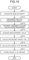
- FIG. 10 is a flowchart illustrating a method for calculating the angle of repose according to the embodiment.
- the operator causes the controller 50 to start processing of calculating the angle ⁇ of repose before the first excavation work for the head 210 of earth.
- the operator excavates the head 210 of earth with the bucket 13 and holds the excavated object 300 (step SP11). More specifically, as illustrated in FIG. 8 , after excavating the head 210 of earth in such a way that the inside of the bucket 13 is fully loaded with the excavated object 300, the operator causes the bucket 13 to perform the tilting operation in such a way that the excavated object 300 is held in the bucket 13.
- the operator discharges a part of the excavated object 300 in the bucket 13 (step SP12). More specifically, the operator causes the bucket 13 to perform the dumping operation to such an extent that the excavated object 300 is not completely discharged from the bucket 13 in a state where the bucket 13 is fully loaded with the excavated object 300. For example, the operator causes the bucket 13 to perform the dumping operation between a tilting operation position in step SP11 and a position with the bucket angle ⁇ bk of larger than 0°.
- the surface of the excavated object 300 held in the bucket 13 maintains the inclination in which the surface of the excavated object 300 remains at a predetermined position without sliding down with the blade end portion 13A as a starting point as illustrated in FIG. 9 .
- the angle of the surface of the excavated object 300 in the bucket 13 maintains the angle of repose.
- step SP13 the operator transmits, to the controller 50, a command to start processing of calculating the angle ⁇ of repose (step SP13). More specifically, when the operator operates the operator command device 26, the operator command device 26 outputs, to the controller 50, an operation command signal to start processing of calculating the angle ⁇ of repose.
- the controller 50 acquires measurement values from a plurality of sensors (step SP14). More specifically, the measurement value acquisition unit 60 acquires the vehicle body inclination angle ⁇ a, the boom angle ⁇ b, the bell crank angle ⁇ c, and the weight Wa of the excavated object 300 in a state where the surface of the excavated object 300 held by the bucket 13 on the YZ plane maintains the angle of repose.
- the controller 50 calculates the bucket angle ⁇ bk (step SP15). More specifically, the bucket angle calculation unit 71 calculates the bucket angle ⁇ bk based on the vehicle body inclination angle ⁇ a, the boom angle ⁇ b, and the bell crank angle ⁇ c acquired by the measurement value acquisition unit 60.
- the controller 50 calculates the angle ⁇ of repose (step SP16). More specifically, the angle-of-repose calculation unit 72 calculates the angle ⁇ of repose based on detection data of the angle of the vehicle body 2, the specification data or design data of the bucket 13 stored in the bucket data storage unit 130, the weight Wa of the excavated object 300 acquired in step SP14, and the bucket angle ⁇ bk calculated in step SP15.
- the controller 50 stores the angle ⁇ of repose (step SP17). More specifically, the characteristic storage unit 120 stores the angle ⁇ of repose calculated by the angle-of-repose calculation unit 72.
- the angle ⁇ of repose of the excavated object 300 can be calculated from the shape data of the bucket 13 stored in the bucket data storage unit 130, the bucket angle ⁇ bk, and the data of the excavated object 300 including the weight W of the excavated object 300 measured by the weight measurement device 33 and the density ⁇ of the excavated object 300 stored in the characteristic storage unit 120.
- the shape data of the bucket 13 includes the length L, the width H, the blade side opening angle ⁇ ap, and the upper side opening angle ⁇ sp of the bucket 13.
- the angle ⁇ of repose can be calculated using the specification data or design data of the bucket 13.
- the angle ⁇ of repose can be calculated using the shape data of the bucket 13 stored in order to perform a predetermined work by the wheel loader 1.
- the bucket angle ⁇ bk can be calculated based on the detection data of the angle of the vehicle body 2 of the wheel loader 1 that supports the working equipment 6 and detection data of an angle of the working equipment 6.
- the surface of the excavated object 300 can have the angle of repose by an operation normally performed by the wheel loader 1. According to the embodiment, it is possible to easily calculate the angle ⁇ of repose without causing the wheel loader 1 to perform an operation different from a normal operation.
- FIG. 11 is a schematic diagram illustrating another example of the loading machine.
- the angle ⁇ of repose may be calculated by a first loading machine 1S as a master machine, and the calculated angle ⁇ of repose may be transmitted to a second loading machine 1T as a slave machine via a communication system.
- the communication system include the Internet, a local area network (LAN), a mobile phone communication network, and a satellite communication network.
- step SP12 and step SP13 may be reversed.
- the operator transmits, to the controller 50, a command to start processing of calculating the angle ⁇ of repose.
- the wheel loader 1 may automatically discharge a part of the excavated object 300 in the bucket 13.
- steps SP11 and SP12 of the flowchart illustrated in FIG. 10 may be autonomously performed by the loading machine 1 without an operation by the operator.
- the operator command device 26 is a switch, but is not limited thereto.
- the operator command device 26 may be, for example, a touch screen or a microphone.
- the touch screen includes a display and a touch panel.
- the operator may operate the touch screen to output a command to start processing of calculating the angle ⁇ of repose to the controller 50.
- a command to start processing of calculating the angle ⁇ of repose may be output to the controller 50 based on a speech input via the microphone.
- the loading machine 1 may be operated by a remote system.
- a device having a function of the controller 50 and including a remote operation device is provided at a remote operation place.
- the angle ⁇ of repose may be calculated remotely.
- the loading machine 1 is a wheel loader, but the loading machine 1 is not limited thereto.
- the loading machine 1 may be an excavator including loading type working equipment.
- the loading machine 1 may be an excavator including backhoe-type working equipment in which the opening portion 136 of the bucket 13 faces rearward in the excavation work.
Landscapes
- Engineering & Computer Science (AREA)
- Mining & Mineral Resources (AREA)
- Civil Engineering (AREA)
- General Engineering & Computer Science (AREA)
- Structural Engineering (AREA)
- Mechanical Engineering (AREA)
- Operation Control Of Excavators (AREA)
- Shovels (AREA)
- Component Parts Of Construction Machinery (AREA)
Applications Claiming Priority (2)
| Application Number | Priority Date | Filing Date | Title |
|---|---|---|---|
| JP2021203509A JP7830111B2 (ja) | 2021-12-15 | 2021-12-15 | バケットに保持された掘削物の安息角を算出するための方法、バケットに保持された掘削物の安息角を算出するためのシステム、及び積込機械 |
| PCT/JP2022/045610 WO2023112878A1 (ja) | 2021-12-15 | 2022-12-12 | バケットに保持された掘削物の安息角を算出するための方法、バケットに保持された掘削物の安息角を算出するためのシステム、及び積込機械 |
Publications (2)
| Publication Number | Publication Date |
|---|---|
| EP4407101A1 true EP4407101A1 (de) | 2024-07-31 |
| EP4407101A4 EP4407101A4 (de) | 2025-09-17 |
Family
ID=86774725
Family Applications (1)
| Application Number | Title | Priority Date | Filing Date |
|---|---|---|---|
| EP22907402.6A Pending EP4407101A4 (de) | 2021-12-15 | 2022-12-12 | Verfahren zur berechnung des ruhewinkels von in einem eimer gehaltenem bodenaushub, system zur berechnung des ruhewinkels von in einem eimer gehaltenem bodenaushub und lademaschine |
Country Status (4)
| Country | Link |
|---|---|
| US (1) | US12655615B2 (de) |
| EP (1) | EP4407101A4 (de) |
| JP (2) | JP7830111B2 (de) |
| WO (1) | WO2023112878A1 (de) |
Family Cites Families (8)
| Publication number | Priority date | Publication date | Assignee | Title |
|---|---|---|---|---|
| US6552279B1 (en) | 2000-09-28 | 2003-04-22 | Caterpillar Inc | Method and apparatus configured to perform viscosity compensation for a payload measurement system |
| DE10146421A1 (de) | 2000-09-28 | 2002-05-08 | Caterpillar Inc | Verfahren und Vorrichtung, die zur Ausführung einer Viskositätskompensation für ein Nutzlastmeßsystem konfiguriert ist |
| WO2016159839A1 (en) * | 2015-03-30 | 2016-10-06 | Volvo Construction Equipment Ab | System and method for determining the material loading condition of a bucket of a material moving machine |
| JP6915007B2 (ja) | 2015-08-24 | 2021-08-04 | 株式会社小松製作所 | ホイールローダ |
| JP2017043885A (ja) | 2015-08-24 | 2017-03-02 | 株式会社小松製作所 | ホイールローダ |
| JP7154026B2 (ja) | 2018-03-30 | 2022-10-17 | 株式会社小松製作所 | 作業機械の制御装置、掘削機械の制御装置、及び作業機械の制御方法 |
| JP7311250B2 (ja) | 2018-08-31 | 2023-07-19 | 株式会社小松製作所 | 作業機械の運搬物特定装置、作業機械、作業機械の運搬物特定方法、補完モデルの生産方法、および学習用データセット |
| JP7289701B2 (ja) | 2019-03-29 | 2023-06-12 | 住友重機械工業株式会社 | ショベル |
-
2021
- 2021-12-15 JP JP2021203509A patent/JP7830111B2/ja active Active
-
2022
- 2022-12-12 US US18/704,485 patent/US12655615B2/en active Active
- 2022-12-12 WO PCT/JP2022/045610 patent/WO2023112878A1/ja not_active Ceased
- 2022-12-12 EP EP22907402.6A patent/EP4407101A4/de active Pending
-
2026
- 2026-02-27 JP JP2026031202A patent/JP2026083203A/ja active Pending
Also Published As
| Publication number | Publication date |
|---|---|
| US20250237039A1 (en) | 2025-07-24 |
| EP4407101A4 (de) | 2025-09-17 |
| JP7830111B2 (ja) | 2026-03-16 |
| JP2026083203A (ja) | 2026-05-19 |
| US12655615B2 (en) | 2026-06-16 |
| WO2023112878A1 (ja) | 2023-06-22 |
| JP2023088646A (ja) | 2023-06-27 |
Similar Documents
| Publication | Publication Date | Title |
|---|---|---|
| EP3733981B1 (de) | Steuervorrichtung einer arbeitsmaschine und steuerungsverfahren einer arbeitsmaschine | |
| JP7461265B2 (ja) | 積込機械の制御システム、積込機械、及び積込機械の制御方法 | |
| US11169018B2 (en) | Construction machine including a display device displaying the weight of a work object | |
| JP7204366B2 (ja) | 作業機械を制御するためのシステム及び方法 | |
| JP7156898B2 (ja) | 運搬車両と運搬車両に素材を積み込む作業機械とを含むシステム、方法、及び作業機械 | |
| JP7274831B2 (ja) | 作業機械 | |
| JP7199865B2 (ja) | 作業機械を制御するためのシステム及び方法 | |
| JP7236826B2 (ja) | 作業機械 | |
| JP7199864B2 (ja) | 作業機械を制御するためのシステム及び方法 | |
| US11959255B2 (en) | Work machine control device, excavating machine control device, and work machine control method | |
| CN115777036B (zh) | 挖掘信息处理装置、工作装置械、挖掘辅助装置及挖掘信息处理方法 | |
| US20250333930A1 (en) | Control system, loading machine, and control method | |
| CN114341435B (zh) | 工程机械 | |
| JP2022156425A (ja) | 作業機械及び搬送物重量計測システム | |
| US20250237039A1 (en) | Method for calculating angle of repose of excavated object held by bucket, system for calculating angle of repose of excavated object held by bucket, and loading machine | |
| CN116964279A (zh) | 作业机械的控制系统及作业机械的控制方法 | |
| US20250327273A1 (en) | Control system, loading machine, and control method | |
| CN114555890B (zh) | 工程机械 | |
| EP4545713A1 (de) | System mit einer arbeitsmaschine und verfahren zur steuerung einer arbeitsmaschine | |
| WO2026048102A1 (ja) | 作業機械 | |
| JP2026042380A (ja) | システム、作業機械、及び方法 | |
| KR20260040075A (ko) | 작업 기계 |
Legal Events
| Date | Code | Title | Description |
|---|---|---|---|
| STAA | Information on the status of an ep patent application or granted ep patent |
Free format text: STATUS: THE INTERNATIONAL PUBLICATION HAS BEEN MADE |
|
| PUAI | Public reference made under article 153(3) epc to a published international application that has entered the european phase |
Free format text: ORIGINAL CODE: 0009012 |
|
| STAA | Information on the status of an ep patent application or granted ep patent |
Free format text: STATUS: REQUEST FOR EXAMINATION WAS MADE |
|
| 17P | Request for examination filed |
Effective date: 20240426 |
|
| AK | Designated contracting states |
Kind code of ref document: A1 Designated state(s): AL AT BE BG CH CY CZ DE DK EE ES FI FR GB GR HR HU IE IS IT LI LT LU LV MC ME MK MT NL NO PL PT RO RS SE SI SK SM TR |
|
| DAV | Request for validation of the european patent (deleted) | ||
| DAX | Request for extension of the european patent (deleted) | ||
| A4 | Supplementary search report drawn up and despatched |
Effective date: 20250814 |
|
| RIC1 | Information provided on ipc code assigned before grant |
Ipc: E02F 3/34 20060101AFI20250808BHEP Ipc: E02F 3/43 20060101ALI20250808BHEP Ipc: E02F 9/26 20060101ALI20250808BHEP |