EP4406675A1 - Riveting apparatus capable of preventing occurrence of omission of fastening, and riveting method using same - Google Patents
Riveting apparatus capable of preventing occurrence of omission of fastening, and riveting method using same Download PDFInfo
- Publication number
- EP4406675A1 EP4406675A1 EP23860719.6A EP23860719A EP4406675A1 EP 4406675 A1 EP4406675 A1 EP 4406675A1 EP 23860719 A EP23860719 A EP 23860719A EP 4406675 A1 EP4406675 A1 EP 4406675A1
- Authority
- EP
- European Patent Office
- Prior art keywords
- riveting
- unit
- moving
- locking
- guide
- Prior art date
- Legal status (The legal status is an assumption and is not a legal conclusion. Google has not performed a legal analysis and makes no representation as to the accuracy of the status listed.)
- Granted
Links
Images


Classifications
-
- B—PERFORMING OPERATIONS; TRANSPORTING
- B21—MECHANICAL METAL-WORKING WITHOUT ESSENTIALLY REMOVING MATERIAL; PUNCHING METAL
- B21J—FORGING; HAMMERING; PRESSING METAL; RIVETING; FORGE FURNACES
- B21J15/00—Riveting
- B21J15/10—Riveting machines
- B21J15/12—Riveting machines with tools or tool parts having a movement additional to the feed movement, e.g. spin
-
- B—PERFORMING OPERATIONS; TRANSPORTING
- B21—MECHANICAL METAL-WORKING WITHOUT ESSENTIALLY REMOVING MATERIAL; PUNCHING METAL
- B21J—FORGING; HAMMERING; PRESSING METAL; RIVETING; FORGE FURNACES
- B21J15/00—Riveting
- B21J15/10—Riveting machines
- B21J15/105—Portable riveters
-
- B—PERFORMING OPERATIONS; TRANSPORTING
- B21—MECHANICAL METAL-WORKING WITHOUT ESSENTIALLY REMOVING MATERIAL; PUNCHING METAL
- B21J—FORGING; HAMMERING; PRESSING METAL; RIVETING; FORGE FURNACES
- B21J15/00—Riveting
- B21J15/02—Riveting procedures
-
- B—PERFORMING OPERATIONS; TRANSPORTING
- B21—MECHANICAL METAL-WORKING WITHOUT ESSENTIALLY REMOVING MATERIAL; PUNCHING METAL
- B21J—FORGING; HAMMERING; PRESSING METAL; RIVETING; FORGE FURNACES
- B21J15/00—Riveting
- B21J15/10—Riveting machines
- B21J15/16—Drives for riveting machines; Transmission means therefor
-
- B—PERFORMING OPERATIONS; TRANSPORTING
- B21—MECHANICAL METAL-WORKING WITHOUT ESSENTIALLY REMOVING MATERIAL; PUNCHING METAL
- B21J—FORGING; HAMMERING; PRESSING METAL; RIVETING; FORGE FURNACES
- B21J15/00—Riveting
- B21J15/10—Riveting machines
- B21J15/16—Drives for riveting machines; Transmission means therefor
- B21J15/20—Drives for riveting machines; Transmission means therefor operated by hydraulic or liquid pressure
-
- B—PERFORMING OPERATIONS; TRANSPORTING
- B21—MECHANICAL METAL-WORKING WITHOUT ESSENTIALLY REMOVING MATERIAL; PUNCHING METAL
- B21J—FORGING; HAMMERING; PRESSING METAL; RIVETING; FORGE FURNACES
- B21J15/00—Riveting
- B21J15/10—Riveting machines
- B21J15/28—Control devices specially adapted to riveting machines not restricted to one of the preceding subgroups
-
- B—PERFORMING OPERATIONS; TRANSPORTING
- B21—MECHANICAL METAL-WORKING WITHOUT ESSENTIALLY REMOVING MATERIAL; PUNCHING METAL
- B21J—FORGING; HAMMERING; PRESSING METAL; RIVETING; FORGE FURNACES
- B21J15/00—Riveting
- B21J15/10—Riveting machines
- B21J15/30—Particular elements, e.g. supports; Suspension equipment specially adapted for portable riveters
-
- B—PERFORMING OPERATIONS; TRANSPORTING
- B21—MECHANICAL METAL-WORKING WITHOUT ESSENTIALLY REMOVING MATERIAL; PUNCHING METAL
- B21J—FORGING; HAMMERING; PRESSING METAL; RIVETING; FORGE FURNACES
- B21J15/00—Riveting
- B21J15/38—Accessories for use in connection with riveting, e.g. pliers for upsetting; Hand tools for riveting
- B21J15/44—Rivet hole positioners
-
- G—PHYSICS
- G01—MEASURING; TESTING
- G01B—MEASURING LENGTH, THICKNESS OR SIMILAR LINEAR DIMENSIONS; MEASURING ANGLES; MEASURING AREAS; MEASURING IRREGULARITIES OF SURFACES OR CONTOURS
- G01B11/00—Measuring arrangements characterised by the use of optical techniques
-
- G—PHYSICS
- G01—MEASURING; TESTING
- G01S—RADIO DIRECTION-FINDING; RADIO NAVIGATION; DETERMINING DISTANCE OR VELOCITY BY USE OF RADIO WAVES; LOCATING OR PRESENCE-DETECTING BY USE OF THE REFLECTION OR RERADIATION OF RADIO WAVES; ANALOGOUS ARRANGEMENTS USING OTHER WAVES
- G01S17/00—Systems using the reflection or reradiation of electromagnetic waves other than radio waves, e.g. lidar systems
- G01S17/02—Systems using the reflection of electromagnetic waves other than radio waves
- G01S17/06—Systems determining position data of a target
- G01S17/46—Indirect determination of position data
- G01S17/48—Active triangulation systems, i.e. using the transmission and reflection of electromagnetic waves other than radio waves
-
- B—PERFORMING OPERATIONS; TRANSPORTING
- B21—MECHANICAL METAL-WORKING WITHOUT ESSENTIALLY REMOVING MATERIAL; PUNCHING METAL
- B21J—FORGING; HAMMERING; PRESSING METAL; RIVETING; FORGE FURNACES
- B21J15/00—Riveting
- B21J15/10—Riveting machines
- B21J15/14—Riveting machines specially adapted for riveting specific articles, e.g. brake lining machines
-
- Y—GENERAL TAGGING OF NEW TECHNOLOGICAL DEVELOPMENTS; GENERAL TAGGING OF CROSS-SECTIONAL TECHNOLOGIES SPANNING OVER SEVERAL SECTIONS OF THE IPC; TECHNICAL SUBJECTS COVERED BY FORMER USPC CROSS-REFERENCE ART COLLECTIONS [XRACs] AND DIGESTS
- Y02—TECHNOLOGIES OR APPLICATIONS FOR MITIGATION OR ADAPTATION AGAINST CLIMATE CHANGE
- Y02E—REDUCTION OF GREENHOUSE GAS [GHG] EMISSIONS, RELATED TO ENERGY GENERATION, TRANSMISSION OR DISTRIBUTION
- Y02E60/00—Enabling technologies; Technologies with a potential or indirect contribution to GHG emissions mitigation
- Y02E60/10—Energy storage using batteries
-
- Y—GENERAL TAGGING OF NEW TECHNOLOGICAL DEVELOPMENTS; GENERAL TAGGING OF CROSS-SECTIONAL TECHNOLOGIES SPANNING OVER SEVERAL SECTIONS OF THE IPC; TECHNICAL SUBJECTS COVERED BY FORMER USPC CROSS-REFERENCE ART COLLECTIONS [XRACs] AND DIGESTS
- Y10—TECHNICAL SUBJECTS COVERED BY FORMER USPC
- Y10T—TECHNICAL SUBJECTS COVERED BY FORMER US CLASSIFICATION
- Y10T29/00—Metal working
- Y10T29/53—Means to assemble or disassemble
- Y10T29/5343—Means to drive self-piercing work part
Definitions
- the present invention relates to a riveting apparatus capable of preventing fastening omission and a riveting method using the same, and more particularly to a riveting apparatus capable of moving a riveting unit to a riveting position, thereby preventing fastening omission, and a riveting method using the same.
- Secondary batteries which are capable of being charged and discharged, are intimately used in daily life.
- secondary batteries are used in mobile devices, electric vehicles, and hybrid electric vehicles.
- a battery module when a battery module is manufactured, a plurality of battery cells is received in a module case, and the module case is sealed using a rivet gun in order to protect the same.
- a worker individually fastens a fastening member, such as a bolt, to a fastening position by directly operating the rivet gun, whereby fastening omission occurs, which leads to defects.
- a fastening member such as a bolt
- Patent Document 1 Korean Patent Application Publication No. 2005-0015633
- the present invention has been made in view of the above problems, and it is an object of the present invention to provide a riveting apparatus capable of preventing fastening omission that is capable of preventing the occurrence of a defect due to fastening omission of a fastening member during a riveting process and a riveting method using the same.
- a riveting apparatus includes a riveting unit (100), a moving unit (200) connected to the riveting unit (100), the moving unit being configured to move the riveting unit, a first moving guide unit (300) configured to guide the longitudinal (X-axis) movement of the moving unit (200), a pair of second moving guide units (400) located at longitudinal opposite ends of the first moving guide unit (300), the pair of second moving guide units being configured to guide the transverse (Y-axis) movement of the first moving guide unit (300), a first position sensor (500) provided under one end of the first moving guide unit (300), and a second position sensor (600) provided under one end of one of the pair of second moving guide units (400).
- the riveting unit (100) may include a riveting unit body (110), a riveting unit head (120) provided under the riveting unit body (110), a switch (130) located at a side surface of an upper end of the riveting unit body (110), and a locking unit (140) located at a lower end of the switch (130).
- the locking unit (140) may include a locking unit body (141) connected to the riveting unit body (110) and a locking controller (142) partially inserted in the locking unit body (141).
- the locking unit body (141) may have a hydraulic device mounted therein, and the locking controller (142) may be configured to be moved upwards and downwards by the hydraulic device.
- the moving unit (200) may include a moving unit body (210), a guide rail (220) formed at a side surface of the moving unit body (210) so as to extend in a height (Z-axis) direction, a first connection portion (230) configured to connect the guide rail (220) and the riveting unit (100) to each other, and a second connection portion (240) configured to connect the moving unit body (210)and the first movement shaft (300) to each other, and the first connection portion (230) may be moved along the guide rail (220) in a vertical direction.
- the first moving guide unit (300) may include a first movement shaft (310), a third connection portion (320) located at each of opposite ends of the first movement shaft (310), and a cover member (330) configured to cover a part of the area of one of the third connection portions (320).
- each of the second moving guide unit (400) may include a second movement shaft (410) and a support member (420) located at each of opposite ends of the second movement shaft (410).
- the first position sensor (500) may be a laser sensor using a laser.
- the laser sensor may radiate a laser toward the second connection portion (240).
- the second position sensor (600) may be a laser sensor using a laser.
- the laser sensor may radiate a laser toward the third connection portion (320).
- the first movement shaft (310) may be formed in two or more.
- a riveting method using the riveting apparatus includes the steps of moving the riveting unit, determining whether the riveting unit is at a correct position, performing a riveting process through the riveting unit, and moving the riveting unit to the next position.
- the riveting unit when the riveting unit is not at the correct position in the step of determining whether the riveting unit is at the correct position, the riveting unit may be locked by the locking unit.
- the step of determining whether the riveting unit is at the correct position and the subsequent steps may be performed again.
- the present invention provides a battery module manufactured using the riveting apparatus having the above-described features.
- a riveting apparatus capable of preventing fastening omission according to the present invention and a riveting method using the same have an advantage in that a first position sensor and a second position sensor are provided to measure the coordinates of a riveting unit, whereby it is possible to prevent fastening omission of a fastening member.
- the riveting apparatus capable of preventing fastening omission according to the present invention and the riveting method using the same have an advantage in that a locking unit is provided at the riveting unit, whereby it is possible to prevent fastening at an incorrect position, and therefore it is possible to prevent production of defective products.
- FIG. 1 is a perspective view showing a riveting apparatus according to a preferred embodiment of the present invention
- FIG. 2 is a plan view showing a riveting unit in the riveting apparatus according to the preferred embodiment of the present invention.
- the riveting apparatus includes a riveting unit 100, a moving unit 200, a first moving guide unit 300, a fourth moving guide unit 400, a first position sensor 500, and a second position sensor 600.
- the riveting unit 100 which is configured to fasten a fastening member at a predetermined position, includes a riveting unit body 110, a riveting unit head 120, a switch 130, and a locking unit 140.
- the riveting unit body 110 may be formed in the shape of a column. In the figure, the riveting unit body is shown as being formed in a cylindrical shape; however, the present invention is not limited thereto.
- the riveting unit body 110 may have a hydraulic device (not shown) mounted therein.
- the riveting unit head 120 is located at a lower end of the riveting unit body 110, is brought into tight contact with a fastening member (not shown) in order to fasten the fastening member to an object, and fastens the fastening member using hydraulic pressure received through the hydraulic device mounted in the riveting unit body 110.
- the switch 130 is provided at the side of the riveting unit body 110, and when pressed by a worker, transmits a signal to the hydraulic device mounted in the riveting unit body 110 such that hydraulic pressure is supplied in a direction toward the riveting unit head 120.
- the locking unit 140 may include a locking unit body 141 and a locking controller 142.
- the locking unit body 141 may be located at the side of the riveting unit body 110, and at this time the locking unit body may be located so as to overlap the switch 130 on a vertical extension line.
- the locking unit body 141 may have a hydraulic device mounted therein.
- the locking controller 142 may be formed in the shape of a bar, a part of the locking controller may be inserted into the locking unit body 141 or may extend through the locking unit body 141, and the locking controller 142 may be moved upwards and downwards by the hydraulic device mounted in the locking unit body 141.
- the locking controller 142 may be moved upwards by the hydraulic device of the locking unit body 141, whereby the locking controller comes into contact with the switch 130 to stop a riveting process, as shown in (a) of FIG. 2 .
- the locking controller 142 may be moved downwards by the hydraulic device of the locking unit body 141, whereby the riveting process may be continued, as shown in (b) of FIG. 2 .
- the moving unit 200 may include a moving unit body 210, a guide rail 220, a first connection portion 230, and a second connection portion 240.
- the moving unit body 210 may be formed in the shape of a flat plate, as shown in the figure; however, the present invention is not limited thereto, and the moving unit body may be formed in the shape of a column.
- the guide rail 220 may be located at one side of the moving unit body 210, and may be connected to the first connection portion 230 to move and guide the first connection portion 230 in a vertical direction.
- One side of the first connection portion 230 is connected to the guide rail 220, as described above, and the other side of the first connection portion is connected to the riveting unit body 110 of the riveting unit 100 to allow the riveting unit 100 to move along the guide rail 220 in the vertical direction.
- the second connection portion 240 is located at an upper part of the moving unit body 210, and allows the moving unit body 210 and the riveting unit 100 connected to the moving unit 200 to move along a first movement shaft 310 of the first moving guide unit 300 and the moving unit body 210 in an X-axis direction shown in the figure.
- the first moving guide unit 300 may include a first movement shaft 310, a third connection portion 320, and a cover member 330.
- the first movement shaft 310 may be connected to the second connection portion 240 of the moving unit 200 to guide the movement of the first moving unit 200 in the X-axis direction.
- first movement shafts 310 are preferably provided, and the first movement shafts may be connected to the second connection portion 240.
- the third connection portion 320 may be formed at each end of the first movement shaft 310.
- each of the third connection portions 320 is connected to the first movement shaft 310 and the other side of each of the third connection portions is connected to a second movement shaft 410 of the second moving guide unit 400 to allow the first moving guide unit 300 to move along the second movement shaft 410.
- the cover member 330 may be formed at an upper surface, a lower surface, and side surfaces of one of the third connection portions 320, and may not be formed at the side surface thereof in a direction toward the second movement shaft 410.
- the second moving guide unit 400 may include a second movement shaft 410 and a support member 420.
- the second movement shaft 410 may be located at each of opposite ends of the first movement shaft 310 at a right angle.
- Each of the second movement shafts 410 may be connected to the first movement shaft 310 via the third connection portion 320, and may guide the movement of the first moving guide unit 300 in a Y-axis direction.
- the support member 420 may be provided at each end of the second movement shaft 410, and the support member 420 may be connected and fastened to a wall of an installation site, another apparatus, etc. to support and fix the riveting apparatus according to the present invention.
- the support member 420 may be installed at a required position by a bolt or an adhesive, and any support and fastening method may be used without limitation as long as it is possible to install the support member at a required position.
- the first position sensor 500 may be a laser sensor configured to radiate a laser, and may be located under the third connection portion 320 at one side of the first moving guide unit 300, more preferably at a lower surface of the cover member 330.
- the first position sensor 500 radiates a laser toward the second connection portion 240 of the moving unit 200 to measure the position coordinates of the riveting unit 100 in the X-axis direction.
- the second position sensor 600 may be a laser sensor configured to radiate a laser, and may be located under the support member 420 located at one side of the plurality of support members 420 of the second moving guide unit 400.
- the second position sensor 600 radiates a laser toward the third connection portion 320 of the first moving guide unit 300 to measure the position coordinates of the riveting unit 100 in the Y-axis direction.
- the first position sensor 500 and the second position sensor 600 radiate lasers to measure the XY-axis coordinates of the riveting unit 100 such that the riveting unit can be moved to the position having the measured coordinates.
- the fastening position may be managed as coordinates through the first position sensor 500 and the second position sensor 600, whereby it is possible to prevent omission of fastening members at all positions.
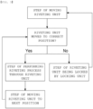
- FIG. 3 is a flowchart illustrating a riveting method using the riveting apparatus according to the present invention.
- the riveting method using the riveting apparatus may include a step of moving the riveting unit 100, a step of determining whether the riveting unit 100 is at a correct position, a step of performing a riveting process through the riveting unit 100, and a step of moving the riveting unit 100 to the next position.
- the step of moving the riveting unit 100 is a step of moving the riveting unit 100 to predetermined coordinates through the moving unit 200, the first moving guide unit 300, and the second moving guide unit 400.
- the step of determining whether the riveting unit 100 is at the correct position is a step of measuring the XY-axis coordinates of the riveting unit 100 through the first position sensor 500 and the second position sensor 600 and determining whether the measured coordinates coincide with predetermined coordinates.
- the locking controller 142 of the locking unit 140 may be moved upwards to prevent operation of the switch 130, thereby preventing fastening at an incorrect position.
- a step of moving the riveting unit 100 to the predetermined coordinates again may be further performed in the state in which the operation of the switch 130 is prevented by the locking controller 142.
- the step of performing the riveting process through the riveting unit 100 is a step in which the riveting unit 100 moved downwards along the guide rail 220 fastens a fastening member to an object after the riveting unit 100 is located at the predetermined coordinates.
- the step of moving the riveting unit 100 to the next position is a step in which the riveting unit 100 is moved upwards along the guide rail 220 and is then moved to the next fastening position by the moving unit 200, the first moving guide unit 300, and the second moving guide unit 400 after the fastening member is fastened through the riveting unit 100.
- the step of determining whether the riveting unit 100 is at the correct position, the step of performing the riveting process through the riveting unit 100, and the step of moving the riveting unit 100 to the next position may be repeated.
- the present invention may be a battery module manufactured using the aforementioned riveting apparatus.
- the present invention may be a device having the battery module according to the present invention mounted therein.
- the device may be an electronic device including a large-capacity battery, such as an electric vehicle, a hybrid electric vehicle, or a plug-in hybrid electric vehicle.
Landscapes
- Engineering & Computer Science (AREA)
- Mechanical Engineering (AREA)
- Physics & Mathematics (AREA)
- Electromagnetism (AREA)
- General Physics & Mathematics (AREA)
- Computer Networks & Wireless Communication (AREA)
- Radar, Positioning & Navigation (AREA)
- Remote Sensing (AREA)
- Automatic Assembly (AREA)
- Length Measuring Devices By Optical Means (AREA)
- Battery Mounting, Suspending (AREA)
- Insertion Pins And Rivets (AREA)
Abstract
Description
- This application claims the benefit of priority to
Korean Patent Application No. 2022-0109710 filed on August 31, 2022 - The present invention relates to a riveting apparatus capable of preventing fastening omission and a riveting method using the same, and more particularly to a riveting apparatus capable of moving a riveting unit to a riveting position, thereby preventing fastening omission, and a riveting method using the same.
- With recent development of alternative energies due to air pollution and energy depletion caused as the result of use of fossil fuels, demand for secondary batteries capable of storing electrical energy that is produced has increased. Secondary batteries, which are capable of being charged and discharged, are intimately used in daily life. For example, secondary batteries are used in mobile devices, electric vehicles, and hybrid electric vehicles.
- Required capacities of secondary batteries used as energy sources of various kinds of electronic devices inevitably used in modern society have been increased due to an increase in usage of mobile devices, increasing complexity of the mobile devices, and development of electric vehicles. In order to satisfy demand of users, a plurality of battery cells is disposed in a small-sized device, whereas a battery module including a plurality of battery cells electrically connected to each other or a battery pack including a plurality of battery modules is used in a vehicle, etc.
- Meanwhile, when a battery module is manufactured, a plurality of battery cells is received in a module case, and the module case is sealed using a rivet gun in order to protect the same.
- During a riveting process, however, a worker individually fastens a fastening member, such as a bolt, to a fastening position by directly operating the rivet gun, whereby fastening omission occurs, which leads to defects.
- Therefore, there are limitations in the worker checking fastening positions one by one during the riveting process, resulting in fastening omission and production of defective products, which increases costs and reduces production efficiency.
- (Patent Document 1)
Korean Patent Application Publication No. 2005-0015633 - The present invention has been made in view of the above problems, and it is an object of the present invention to provide a riveting apparatus capable of preventing fastening omission that is capable of preventing the occurrence of a defect due to fastening omission of a fastening member during a riveting process and a riveting method using the same.
- It is another object of the present invention to provide a riveting apparatus capable of preventing fastening omission that is capable of preventing fastening at an incorrect position during a riveting process and a riveting method using the same.
- In order to accomplish the above objects, a riveting apparatus according to the present invention includes a riveting unit (100), a moving unit (200) connected to the riveting unit (100), the moving unit being configured to move the riveting unit, a first moving guide unit (300) configured to guide the longitudinal (X-axis) movement of the moving unit (200), a pair of second moving guide units (400) located at longitudinal opposite ends of the first moving guide unit (300), the pair of second moving guide units being configured to guide the transverse (Y-axis) movement of the first moving guide unit (300), a first position sensor (500) provided under one end of the first moving guide unit (300), and a second position sensor (600) provided under one end of one of the pair of second moving guide units (400).
- Also, in the riveting apparatus according to the present invention, the riveting unit (100) may include a riveting unit body (110), a riveting unit head (120) provided under the riveting unit body (110), a switch (130) located at a side surface of an upper end of the riveting unit body (110), and a locking unit (140) located at a lower end of the switch (130).
- Also, in the riveting apparatus according to the present invention, the locking unit (140) may include a locking unit body (141) connected to the riveting unit body (110) and a locking controller (142) partially inserted in the locking unit body (141).
- Also, in the riveting apparatus according to the present invention, the locking unit body (141) may have a hydraulic device mounted therein, and the locking controller (142) may be configured to be moved upwards and downwards by the hydraulic device.
- Also, in the riveting apparatus according to the present invention, the moving unit (200) may include a moving unit body (210), a guide rail (220) formed at a side surface of the moving unit body (210) so as to extend in a height (Z-axis) direction, a first connection portion (230) configured to connect the guide rail (220) and the riveting unit (100) to each other, and a second connection portion (240) configured to connect the moving unit body (210)and the first movement shaft (300) to each other, and the first connection portion (230) may be moved along the guide rail (220) in a vertical direction.
- Also, in the riveting apparatus according to the present invention, the first moving guide unit (300) may include a first movement shaft (310), a third connection portion (320) located at each of opposite ends of the first movement shaft (310), and a cover member (330) configured to cover a part of the area of one of the third connection portions (320).
- Also, in the riveting apparatus according to the present invention, each of the second moving guide unit (400) may include a second movement shaft (410) and a support member (420) located at each of opposite ends of the second movement shaft (410).
- Also, in the riveting apparatus according to the present invention, the first position sensor (500) may be a laser sensor using a laser.
- Also, in the riveting apparatus according to the present invention, the laser sensor may radiate a laser toward the second connection portion (240).
- Also, in the riveting apparatus according to the present invention, the second position sensor (600) may be a laser sensor using a laser.
- Also, in the riveting apparatus according to the present invention, the laser sensor may radiate a laser toward the third connection portion (320).
- Also, in the riveting apparatus according to the present invention, the first movement shaft (310) may be formed in two or more.
- In addition, a riveting method using the riveting apparatus according to the present invention includes the steps of moving the riveting unit, determining whether the riveting unit is at a correct position, performing a riveting process through the riveting unit, and moving the riveting unit to the next position.
- Also, in the riveting method according to the present invention, when the riveting unit is not at the correct position in the step of determining whether the riveting unit is at the correct position, the riveting unit may be locked by the locking unit.
- Also, in the riveting apparatus according to the present invention, after moving the riveting unit again, the step of determining whether the riveting unit is at the correct position and the subsequent steps may be performed again.
- In addition, the present invention provides a battery module manufactured using the riveting apparatus having the above-described features.
- As is apparent from the above description, a riveting apparatus capable of preventing fastening omission according to the present invention and a riveting method using the same have an advantage in that a first position sensor and a second position sensor are provided to measure the coordinates of a riveting unit, whereby it is possible to prevent fastening omission of a fastening member.
- In addition, the riveting apparatus capable of preventing fastening omission according to the present invention and the riveting method using the same have an advantage in that a locking unit is provided at the riveting unit, whereby it is possible to prevent fastening at an incorrect position, and therefore it is possible to prevent production of defective products.
-
-
FIG. 1 is a perspective view showing a riveting apparatus according to a preferred embodiment of the present invention. -
FIG. 2 is a plan view showing a riveting unit in the riveting apparatus according to the preferred embodiment of the present invention. -
FIG. 3 is a flowchart illustrating a riveting method using the riveting apparatus according to the present invention. - Now, preferred embodiments of the present invention will be described in detail with reference to the accompanying drawings such that the preferred embodiments of the present invention can be easily implemented by a person having ordinary skill in the art to which the present invention pertains. In describing the principle of operation of the preferred embodiments of the present invention in detail, however, a detailed description of known functions and configurations incorporated herein will be omitted when the same may obscure the subject matter of the present invention.
- In addition, the same reference numbers will be used throughout the drawings to refer to parts that perform similar functions or operations. In the case in which one part is the to be connected to another part in the entire specification, not only may the one part be directly connected to the other part, but also, the one part may be indirectly connected to the other part via a further part. In addition, that a certain element is included does not mean that other elements are excluded, but means that such elements may be further included unless mentioned otherwise.
- Hereinafter, a riveting apparatus capable of preventing fastening omission according to the present invention and a riveting method using the same will be described with reference to the accompanying drawings.
-
FIG. 1 is a perspective view showing a riveting apparatus according to a preferred embodiment of the present invention, andFIG. 2 is a plan view showing a riveting unit in the riveting apparatus according to the preferred embodiment of the present invention. - Referring to
FIGs. 1 and2 , the riveting apparatus according to the preferred embodiment of the present invention includes a rivetingunit 100, a movingunit 200, a firstmoving guide unit 300, a fourthmoving guide unit 400, afirst position sensor 500, and asecond position sensor 600. - First, the riveting
unit 100, which is configured to fasten a fastening member at a predetermined position, includes a rivetingunit body 110, a rivetingunit head 120, aswitch 130, and alocking unit 140. - The riveting
unit body 110 may be formed in the shape of a column. In the figure, the riveting unit body is shown as being formed in a cylindrical shape; however, the present invention is not limited thereto. - In addition, the riveting
unit body 110 may have a hydraulic device (not shown) mounted therein. - The riveting
unit head 120 is located at a lower end of the rivetingunit body 110, is brought into tight contact with a fastening member (not shown) in order to fasten the fastening member to an object, and fastens the fastening member using hydraulic pressure received through the hydraulic device mounted in the rivetingunit body 110. - The
switch 130 is provided at the side of the rivetingunit body 110, and when pressed by a worker, transmits a signal to the hydraulic device mounted in the rivetingunit body 110 such that hydraulic pressure is supplied in a direction toward the rivetingunit head 120. - The
locking unit 140 may include alocking unit body 141 and alocking controller 142. - The
locking unit body 141 may be located at the side of the rivetingunit body 110, and at this time the locking unit body may be located so as to overlap theswitch 130 on a vertical extension line. - The
locking unit body 141 may have a hydraulic device mounted therein. - The
locking controller 142 may be formed in the shape of a bar, a part of the locking controller may be inserted into thelocking unit body 141 or may extend through thelocking unit body 141, and thelocking controller 142 may be moved upwards and downwards by the hydraulic device mounted in thelocking unit body 141. - When the riveting
unit 100 is moved and deviates from a predetermined position, thelocking controller 142 may be moved upwards by the hydraulic device of thelocking unit body 141, whereby the locking controller comes into contact with theswitch 130 to stop a riveting process, as shown in (a) ofFIG. 2 . - In addition, when the riveting
unit 100 is exactly located at a fastening position, thelocking controller 142 may be moved downwards by the hydraulic device of thelocking unit body 141, whereby the riveting process may be continued, as shown in (b) ofFIG. 2 . - Next, the moving
unit 200 may include a movingunit body 210, aguide rail 220, afirst connection portion 230, and asecond connection portion 240. - The moving
unit body 210 may be formed in the shape of a flat plate, as shown in the figure; however, the present invention is not limited thereto, and the moving unit body may be formed in the shape of a column. - The
guide rail 220 may be located at one side of the movingunit body 210, and may be connected to thefirst connection portion 230 to move and guide thefirst connection portion 230 in a vertical direction. - One side of the
first connection portion 230 is connected to theguide rail 220, as described above, and the other side of the first connection portion is connected to theriveting unit body 110 of theriveting unit 100 to allow theriveting unit 100 to move along theguide rail 220 in the vertical direction. - The
second connection portion 240 is located at an upper part of the movingunit body 210, and allows the movingunit body 210 and theriveting unit 100 connected to the movingunit 200 to move along afirst movement shaft 310 of the first movingguide unit 300 and the movingunit body 210 in an X-axis direction shown in the figure. - Next, the first moving
guide unit 300 may include afirst movement shaft 310, athird connection portion 320, and acover member 330. - The
first movement shaft 310 may be connected to thesecond connection portion 240 of the movingunit 200 to guide the movement of the first movingunit 200 in the X-axis direction. - In this case, two or more
first movement shafts 310 are preferably provided, and the first movement shafts may be connected to thesecond connection portion 240. - This has the advantage that it is possible to prevent the occurrence of positional error factors, such as vibration that may occur when the moving
unit 300 connected to thefirst movement shaft 310 is moved along thefirst movement shaft 310 and twisting of the movingunit 200 when onefirst movement shaft 310 is formed, whereby it is possible to improve accuracy. - The
third connection portion 320 may be formed at each end of thefirst movement shaft 310. - One side of each of the
third connection portions 320 is connected to thefirst movement shaft 310 and the other side of each of the third connection portions is connected to asecond movement shaft 410 of the second movingguide unit 400 to allow the first movingguide unit 300 to move along thesecond movement shaft 410. - The
cover member 330 may be formed at an upper surface, a lower surface, and side surfaces of one of thethird connection portions 320, and may not be formed at the side surface thereof in a direction toward thesecond movement shaft 410. - The second moving
guide unit 400 may include asecond movement shaft 410 and asupport member 420. - The
second movement shaft 410 may be located at each of opposite ends of thefirst movement shaft 310 at a right angle. - Each of the
second movement shafts 410 may be connected to thefirst movement shaft 310 via thethird connection portion 320, and may guide the movement of the first movingguide unit 300 in a Y-axis direction. - The
support member 420 may be provided at each end of thesecond movement shaft 410, and thesupport member 420 may be connected and fastened to a wall of an installation site, another apparatus, etc. to support and fix the riveting apparatus according to the present invention. - The
support member 420 may be installed at a required position by a bolt or an adhesive, and any support and fastening method may be used without limitation as long as it is possible to install the support member at a required position. - The
first position sensor 500 may be a laser sensor configured to radiate a laser, and may be located under thethird connection portion 320 at one side of the first movingguide unit 300, more preferably at a lower surface of thecover member 330. - The
first position sensor 500 radiates a laser toward thesecond connection portion 240 of the movingunit 200 to measure the position coordinates of theriveting unit 100 in the X-axis direction. - The
second position sensor 600 may be a laser sensor configured to radiate a laser, and may be located under thesupport member 420 located at one side of the plurality ofsupport members 420 of the second movingguide unit 400. - The
second position sensor 600 radiates a laser toward thethird connection portion 320 of the first movingguide unit 300 to measure the position coordinates of theriveting unit 100 in the Y-axis direction. - Consequently, the
first position sensor 500 and thesecond position sensor 600 radiate lasers to measure the XY-axis coordinates of theriveting unit 100 such that the riveting unit can be moved to the position having the measured coordinates. - In addition, the fastening position may be managed as coordinates through the
first position sensor 500 and thesecond position sensor 600, whereby it is possible to prevent omission of fastening members at all positions. -
FIG. 3 is a flowchart illustrating a riveting method using the riveting apparatus according to the present invention. - Referring to
FIG. 3 , the riveting method using the riveting apparatus according to the present invention may include a step of moving theriveting unit 100, a step of determining whether theriveting unit 100 is at a correct position, a step of performing a riveting process through theriveting unit 100, and a step of moving theriveting unit 100 to the next position. - The step of moving the
riveting unit 100 is a step of moving theriveting unit 100 to predetermined coordinates through the movingunit 200, the first movingguide unit 300, and the second movingguide unit 400. - The step of determining whether the
riveting unit 100 is at the correct position is a step of measuring the XY-axis coordinates of theriveting unit 100 through thefirst position sensor 500 and thesecond position sensor 600 and determining whether the measured coordinates coincide with predetermined coordinates. - At this time, if the XY-axis coordinates of the
riveting unit 100 measured through thefirst position sensor 500 and thesecond position sensor 600 do not coincide with the predetermined coordinates, the lockingcontroller 142 of thelocking unit 140 may be moved upwards to prevent operation of theswitch 130, thereby preventing fastening at an incorrect position. - In addition, a step of moving the
riveting unit 100 to the predetermined coordinates again may be further performed in the state in which the operation of theswitch 130 is prevented by the lockingcontroller 142. - The step of performing the riveting process through the
riveting unit 100 is a step in which theriveting unit 100 moved downwards along theguide rail 220 fastens a fastening member to an object after theriveting unit 100 is located at the predetermined coordinates. - The step of moving the
riveting unit 100 to the next position is a step in which theriveting unit 100 is moved upwards along theguide rail 220 and is then moved to the next fastening position by the movingunit 200, the first movingguide unit 300, and the second movingguide unit 400 after the fastening member is fastened through theriveting unit 100. - At this time, after being moved to the next fastening position, the step of determining whether the
riveting unit 100 is at the correct position, the step of performing the riveting process through theriveting unit 100, and the step of moving theriveting unit 100 to the next position may be repeated. - The present invention may be a battery module manufactured using the aforementioned riveting apparatus. In addition, the present invention may be a device having the battery module according to the present invention mounted therein. For example, the device may be an electronic device including a large-capacity battery, such as an electric vehicle, a hybrid electric vehicle, or a plug-in hybrid electric vehicle.
- Although the specific details of the present invention have been described in detail, those skilled in the art will appreciate that the detailed description thereof discloses only preferred embodiments of the present invention and thus does not limit the scope of the present invention. Accordingly, those skilled in the art will appreciate that various changes and modifications are possible, without departing from the category and the technical idea of the present invention, and it will be obvious that such changes and modifications fall within the scope of the appended claims.
-
- 100: Riveting unit
- 110: Riveting unit body
- 120: Riveting unit head
- 130: Switch
- 140: Locking unit
- 141: Locking unit body 142: Locking controller
- 200: Moving unit
- 210: Moving unit body
- 220: Guide rail
- 230: First connection portion
- 240: Second connection portion
- 300: First moving guide unit
- 310: First movement shaft
- 320: Third connection portion
- 330: Cover member
- 400: Second moving guide unit
- 410: Second movement shaft
- 420: Support member
- 500: First position sensor
- 600: Second position sensor
Claims (16)
- A riveting apparatus comprising:a riveting unit;a moving unit connected to the riveting unit, the moving unit being configured to move the riveting unit;a first moving guide unit configured to guide a longitudinal movement of the moving unit;a pair of second moving guide units located at longitudinal opposite ends of the first moving guide unit, the pair of second moving guide units being configured to guide a transverse movement of the first moving guide unit;a first position sensor provided under one end of the first moving guide unit; anda second position sensor provided under one end of one of the pair of second moving guide units.
- The riveting apparatus according to claim 1, wherein the riveting unit comprises a riveting unit body, a riveting unit head provided under the riveting unit body, a switch located at a side surface of an upper end of the riveting unit body, and a locking unit located at a lower end of the switch.
- The riveting apparatus according to claim 2, wherein the locking unit comprises a locking unit body connected to the riveting unit body and a locking controller partially inserted in the locking unit body.
- The riveting apparatus according to claim 3, wherein the locking unit body has a hydraulic device mounted therein, and
wherein the locking controller is configured to be moved upwards and downwards by the hydraulic device. - The riveting apparatus according to claim 1, wherein the moving unit comprises a moving unit body, a guide rail formed at a side surface of the moving unit body so as to extend in a height direction, a first connection portion configured to connect the guide rail and the riveting unit to each other, and a second connection portion configured to connect the moving unit body and the first movement shaft to each other, and
wherein the first connection portion is moved along the guide rail in a vertical direction. - The riveting apparatus according to claim 5, wherein the first moving guide unit comprises a first movement shaft, a third connection portion located at each of opposite ends of the first movement shaft, and a cover member configured to cover a part of an area of one of the third connection portions.
- The riveting apparatus according to claim 6, wherein each of the second moving guide units comprises a second movement shaft and a support member located at each of opposite ends of the second movement shaft.
- The riveting apparatus according to claim 7, wherein the first position sensor is a laser sensor using a laser.
- The riveting apparatus according to claim 8, wherein the laser sensor radiates a laser toward the second connection portion.
- The riveting apparatus according to claim 7, wherein the second position sensor is a laser sensor using a laser.
- The riveting apparatus according to claim 10, wherein the laser sensor radiates a laser toward the third connection portion.
- The riveting apparatus according to claim 6, wherein the first movement shaft is formed in two or more.
- A riveting method using the riveting apparatus according to any one of claims 1 to 12, the riveting method comprising:moving the riveting unit;determining whether the riveting unit is at a correct position;performing a riveting process through the riveting unit; andmoving the riveting unit to a next position.
- The riveting method according to claim 13, wherein, when the riveting unit is not at the correct position in the step of determining whether the riveting unit is at the correct position, the riveting unit is locked by the locking unit.
- The riveting method according to claim 13, wherein, after moving the riveting unit again, the step of determining whether the riveting unit is at the correct position and the subsequent steps are performed again.
- A battery module manufactured using the riveting apparatus according to any one of claims 1 to 12.
Applications Claiming Priority (2)
| Application Number | Priority Date | Filing Date | Title |
|---|---|---|---|
| KR1020220109710A KR20240030534A (en) | 2022-08-31 | 2022-08-31 | A Riveting Device Capable Of Preventing Omission Of Fastening And A Riveting Method Using The Same |
| PCT/KR2023/011594 WO2024049039A1 (en) | 2022-08-31 | 2023-08-07 | Riveting apparatus capable of preventing occurrence of omission of fastening, and riveting method using same |
Publications (3)
| Publication Number | Publication Date |
|---|---|
| EP4406675A1 true EP4406675A1 (en) | 2024-07-31 |
| EP4406675A4 EP4406675A4 (en) | 2025-04-30 |
| EP4406675B1 EP4406675B1 (en) | 2026-02-25 |
Family
ID=90098158
Family Applications (1)
| Application Number | Title | Priority Date | Filing Date |
|---|---|---|---|
| EP23860719.6A Active EP4406675B1 (en) | 2022-08-31 | 2023-08-07 | Riveting apparatus capable of preventing fastening in incorrect positions, and riveting method using same |
Country Status (7)
| Country | Link |
|---|---|
| US (1) | US12434294B2 (en) |
| EP (1) | EP4406675B1 (en) |
| JP (1) | JP7852983B2 (en) |
| KR (1) | KR20240030534A (en) |
| CN (1) | CN118119461A (en) |
| ES (1) | ES3064711T3 (en) |
| WO (1) | WO2024049039A1 (en) |
Family Cites Families (32)
| Publication number | Priority date | Publication date | Assignee | Title |
|---|---|---|---|---|
| DE3229034A1 (en) | 1982-08-04 | 1984-02-09 | Dornier Gmbh, 7990 Friedrichshafen | Rivet positioner |
| JPS5989639U (en) * | 1982-12-06 | 1984-06-18 | 豊生ブレ−キ工業株式会社 | Rivet crimping device |
| JPH02262924A (en) * | 1989-03-31 | 1990-10-25 | Toyo Koki:Kk | Caulking work device |
| DE69113919T2 (en) * | 1990-08-08 | 1996-06-20 | Emhart Inc | Rivet setting tool. |
| JP3140510B2 (en) * | 1991-10-09 | 2001-03-05 | 株式会社アマダ | Plate processing machine |
| JP2532345B2 (en) * | 1993-09-30 | 1996-09-11 | ▲吉▼川鐵工株式会社 | Caulking method of caulking machine |
| US5427297A (en) * | 1993-11-09 | 1995-06-27 | Tymianski; Marek | Feeding system for multiple riveting machine |
| KR200160578Y1 (en) | 1997-03-13 | 1999-11-15 | 배길성 | Riveting Detection Device of Motor Housing |
| US6011482A (en) * | 1997-11-26 | 2000-01-04 | The Boeing Company | Fastener protrusion sensor |
| US6523245B2 (en) | 2001-07-10 | 2003-02-25 | Great Dane Limited Partnership | Automated drill and rivet machine |
| US6763564B2 (en) * | 2002-04-04 | 2004-07-20 | Lakewood Engineering And Manufacturing Co. | Automated method and apparatus for driving fasteners into an electric fan assembly |
| KR100485120B1 (en) * | 2002-12-05 | 2005-04-25 | 장동영 | Auto-riveting machine |
| KR100502293B1 (en) | 2003-08-07 | 2005-07-20 | (주)덕흥정밀 | An air gun for solid type rivet |
| JP2006187787A (en) | 2005-01-06 | 2006-07-20 | Nippon Pop Rivets & Fasteners Ltd | Blind rivet fastening device |
| DE102005058493A1 (en) | 2005-12-02 | 2007-06-06 | Dürr Special Material Handling GmbH | processing device |
| US8006362B2 (en) * | 2007-04-06 | 2011-08-30 | The Boeing Company | Method and apparatus for installing fasteners |
| US8956753B2 (en) * | 2010-03-30 | 2015-02-17 | Samsung Sdi Co., Ltd. | Secondary battery and secondary battery module |
| JP2013198918A (en) | 2012-03-23 | 2013-10-03 | Mitsubishi Heavy Ind Ltd | Automatic riveting apparatus |
| KR101404244B1 (en) * | 2012-09-05 | 2014-06-05 | 배연선 | Apparatus for rivetting |
| KR102138604B1 (en) | 2013-10-31 | 2020-07-28 | 주식회사다스 | Bolt fastening inspection method using position sensor |
| KR101574597B1 (en) | 2014-05-13 | 2015-12-04 | 주식회사 삼인이엔지 | Apparatus for fastening automatically bolt |
| ES2753441T3 (en) | 2015-01-16 | 2020-04-08 | Comau Spa | Riveting apparatus |
| KR20180038271A (en) | 2016-10-06 | 2018-04-16 | 한국생산기술연구원 | A hybrid machining equipment and machining method using the same |
| KR101811626B1 (en) | 2016-10-25 | 2017-12-26 | 선문대학교 산학협력단 | Riveting apparatus for manufacturing parts |
| KR101990840B1 (en) | 2017-09-21 | 2019-06-19 | 강태선 | Lock Bol0t Fastening System |
| CN207655830U (en) | 2017-12-25 | 2018-07-27 | 上海闳铖自动化技术有限公司 | A kind of full-automatic nut riveting mechanism |
| CN109229514B (en) | 2018-10-26 | 2020-08-28 | 江苏科技大学 | T-section hollow elevator guide rail assembly equipment and automatic assembly production line and assembly packaging method based thereon |
| CN210966821U (en) | 2019-09-09 | 2020-07-10 | 上海友升铝业有限公司 | Automatic rivet pulling machine for battery frame with transverse floating return mechanism of rivet pulling gun |
| CN214053560U (en) | 2020-11-20 | 2021-08-27 | 上海创志实业有限公司 | Double-gun full-automatic rivet pulling tool |
| KR20220109710A (en) | 2021-01-29 | 2022-08-05 | 주식회사 코너마켓 | Server and method for providing fashion goods consignment sales service |
| KR102394421B1 (en) | 2021-09-01 | 2022-05-06 | 주식회사 시스템알앤디 | Two-point automatic fastening system using automatic variable axis |
| CN113953439B (en) | 2021-11-24 | 2023-03-28 | 重庆赛菱斯智能装备有限公司 | Automatic matching multi-position rivet pulling device |
-
2022
- 2022-08-31 KR KR1020220109710A patent/KR20240030534A/en active Pending
-
2023
- 2023-08-07 US US18/701,768 patent/US12434294B2/en active Active
- 2023-08-07 EP EP23860719.6A patent/EP4406675B1/en active Active
- 2023-08-07 ES ES23860719T patent/ES3064711T3/en active Active
- 2023-08-07 CN CN202380014060.6A patent/CN118119461A/en active Pending
- 2023-08-07 WO PCT/KR2023/011594 patent/WO2024049039A1/en not_active Ceased
- 2023-08-07 JP JP2024514439A patent/JP7852983B2/en active Active
Also Published As
| Publication number | Publication date |
|---|---|
| KR20240030534A (en) | 2024-03-07 |
| EP4406675A4 (en) | 2025-04-30 |
| JP7852983B2 (en) | 2026-04-28 |
| JP2024538491A (en) | 2024-10-23 |
| US20240408666A1 (en) | 2024-12-12 |
| CN118119461A (en) | 2024-05-31 |
| ES3064711T3 (en) | 2026-04-28 |
| US12434294B2 (en) | 2025-10-07 |
| EP4406675B1 (en) | 2026-02-25 |
| WO2024049039A1 (en) | 2024-03-07 |
Similar Documents
| Publication | Publication Date | Title |
|---|---|---|
| US9673430B2 (en) | Power source device, electric vehicle comprising power source device, accumulator device | |
| US8981239B2 (en) | Capacitor module | |
| KR101810659B1 (en) | Electrode Terminal Welding Device of Battery Cell Assembly Comprising Battery Cells and Welding Process Using the Same | |
| US20150144409A1 (en) | Power source device, vehicle provided with power source device, and power storage device | |
| EP4098393B1 (en) | Apparatus for bending and welding electrode lead, and method for welding electrode lead using same | |
| CN112285609A (en) | Conduction detection device and method for plug-in wiring harness, controller and assembling device | |
| US12434294B2 (en) | Riveting apparatus capable of preventing fastening omission and riveting method using the same | |
| KR102369375B1 (en) | Vehicle Battery Laser Welding Device | |
| KR102391340B1 (en) | Bending machine for bus bar | |
| EP4123260A1 (en) | Welding electrode inspection device for measuring whether welding electrode is normal and inspection method using same | |
| KR20170019211A (en) | Pouch sealing gap measuring apparatus | |
| KR101891892B1 (en) | Device of manufacturing cap-plate with safety-vent and membrane | |
| CN219347657U (en) | Battery cell detection device | |
| CN216607714U (en) | Welding equipment | |
| CN217604899U (en) | Battery package crossbeam deflection automated inspection instrument | |
| EP4439776A1 (en) | Pouch cell deformation inspection device and deformation inspection method using same | |
| EP4310986A1 (en) | Bonding state inspection apparatus and bonding state inspection method using same | |
| KR20230075155A (en) | Battery pack and assembling method thereof | |
| KR101945904B1 (en) | Apparatus for casing of battery pack and inspection of core pack and the control method thereof | |
| KR102910528B1 (en) | Multipurpose jig for manufacturing rechargeable battery and setting method of manufacturing apparatus using the same | |
| CN223160893U (en) | Debugging tool | |
| KR20240025219A (en) | Bolting Apparatus of Battery and Bolting Method using the same | |
| KR102833354B1 (en) | Rotary equipment calibration device and battery manufacturing system including same | |
| CN218973368U (en) | Automobile interior trim part positioning column position detection mechanism | |
| CN215470756U (en) | Automobile seat microswitch mounting auxiliary tool |
Legal Events
| Date | Code | Title | Description |
|---|---|---|---|
| STAA | Information on the status of an ep patent application or granted ep patent |
Free format text: STATUS: THE INTERNATIONAL PUBLICATION HAS BEEN MADE |
|
| PUAI | Public reference made under article 153(3) epc to a published international application that has entered the european phase |
Free format text: ORIGINAL CODE: 0009012 |
|
| STAA | Information on the status of an ep patent application or granted ep patent |
Free format text: STATUS: REQUEST FOR EXAMINATION WAS MADE |
|
| 17P | Request for examination filed |
Effective date: 20240425 |
|
| AK | Designated contracting states |
Kind code of ref document: A1 Designated state(s): AL AT BE BG CH CY CZ DE DK EE ES FI FR GB GR HR HU IE IS IT LI LT LU LV MC ME MK MT NL NO PL PT RO RS SE SI SK SM TR |
|
| A4 | Supplementary search report drawn up and despatched |
Effective date: 20250327 |
|
| RIC1 | Information provided on ipc code assigned before grant |
Ipc: G01S 17/48 20060101ALI20250321BHEP Ipc: G01B 11/00 20060101ALI20250321BHEP Ipc: B21J 15/44 20060101ALI20250321BHEP Ipc: B21J 15/02 20060101ALI20250321BHEP Ipc: B21J 15/10 20060101AFI20250321BHEP |
|
| GRAP | Despatch of communication of intention to grant a patent |
Free format text: ORIGINAL CODE: EPIDOSNIGR1 |
|
| STAA | Information on the status of an ep patent application or granted ep patent |
Free format text: STATUS: GRANT OF PATENT IS INTENDED |
|
| INTG | Intention to grant announced |
Effective date: 20251029 |
|
| DAV | Request for validation of the european patent (deleted) | ||
| DAX | Request for extension of the european patent (deleted) | ||
| P01 | Opt-out of the competence of the unified patent court (upc) registered |
Free format text: CASE NUMBER: UPC_APP_0012214_4406675/2025 Effective date: 20251105 |
|
| GRAS | Grant fee paid |
Free format text: ORIGINAL CODE: EPIDOSNIGR3 |
|
| GRAA | (expected) grant |
Free format text: ORIGINAL CODE: 0009210 |
|
| STAA | Information on the status of an ep patent application or granted ep patent |
Free format text: STATUS: THE PATENT HAS BEEN GRANTED |
|
| AK | Designated contracting states |
Kind code of ref document: B1 Designated state(s): AL AT BE BG CH CY CZ DE DK EE ES FI FR GB GR HR HU IE IS IT LI LT LU LV MC ME MK MT NL NO PL PT RO RS SE SI SK SM TR |
|
| REG | Reference to a national code |
Ref country code: CH Ref legal event code: F10 Free format text: ST27 STATUS EVENT CODE: U-0-0-F10-F00 (AS PROVIDED BY THE NATIONAL OFFICE) Effective date: 20260225 Ref country code: GB Ref legal event code: FG4D |
|
| REG | Reference to a national code |
Ref country code: DE Ref legal event code: R096 Ref document number: 602023012764 Country of ref document: DE |
|
| REG | Reference to a national code |
Ref country code: IE Ref legal event code: FG4D |
|
| REG | Reference to a national code |
Ref country code: ES Ref legal event code: FG2A Ref document number: 3064711 Country of ref document: ES Kind code of ref document: T3 Effective date: 20260428 |