EP4406525A1 - Gehhilfevorrichtung mit körpergewichtunterstützung und verfahren zur steuerung davon - Google Patents
Gehhilfevorrichtung mit körpergewichtunterstützung und verfahren zur steuerung davon Download PDFInfo
- Publication number
- EP4406525A1 EP4406525A1 EP22872554.5A EP22872554A EP4406525A1 EP 4406525 A1 EP4406525 A1 EP 4406525A1 EP 22872554 A EP22872554 A EP 22872554A EP 4406525 A1 EP4406525 A1 EP 4406525A1
- Authority
- EP
- European Patent Office
- Prior art keywords
- wearer
- unit
- knee joint
- walking
- joint part
- Prior art date
- Legal status (The legal status is an assumption and is not a legal conclusion. Google has not performed a legal analysis and makes no representation as to the accuracy of the status listed.)
- Granted
Links
Images


Classifications
-
- A—HUMAN NECESSITIES
- A61—MEDICAL OR VETERINARY SCIENCE; HYGIENE
- A61H—PHYSICAL THERAPY APPARATUS, e.g. DEVICES FOR LOCATING OR STIMULATING REFLEX POINTS IN THE BODY; ARTIFICIAL RESPIRATION; MASSAGE; BATHING DEVICES FOR SPECIAL THERAPEUTIC OR HYGIENIC PURPOSES OR SPECIFIC PARTS OF THE BODY
- A61H3/00—Appliances for aiding patients or disabled persons to walk about
-
- A—HUMAN NECESSITIES
- A61—MEDICAL OR VETERINARY SCIENCE; HYGIENE
- A61H—PHYSICAL THERAPY APPARATUS, e.g. DEVICES FOR LOCATING OR STIMULATING REFLEX POINTS IN THE BODY; ARTIFICIAL RESPIRATION; MASSAGE; BATHING DEVICES FOR SPECIAL THERAPEUTIC OR HYGIENIC PURPOSES OR SPECIFIC PARTS OF THE BODY
- A61H1/00—Apparatus for passive exercising; Vibrating apparatus; Chiropractic devices, e.g. body impacting devices, external devices for briefly extending or aligning unbroken bones
- A61H1/02—Stretching or bending or torsioning apparatus for exercising
- A61H1/0237—Stretching or bending or torsioning apparatus for exercising for the lower limbs
- A61H1/0244—Hip
-
- A—HUMAN NECESSITIES
- A61—MEDICAL OR VETERINARY SCIENCE; HYGIENE
- A61H—PHYSICAL THERAPY APPARATUS, e.g. DEVICES FOR LOCATING OR STIMULATING REFLEX POINTS IN THE BODY; ARTIFICIAL RESPIRATION; MASSAGE; BATHING DEVICES FOR SPECIAL THERAPEUTIC OR HYGIENIC PURPOSES OR SPECIFIC PARTS OF THE BODY
- A61H2201/00—Characteristics of apparatus not provided for in the preceding codes
- A61H2201/12—Driving means
- A61H2201/1207—Driving means with electric or magnetic drive
- A61H2201/1215—Rotary drive
-
- A—HUMAN NECESSITIES
- A61—MEDICAL OR VETERINARY SCIENCE; HYGIENE
- A61H—PHYSICAL THERAPY APPARATUS, e.g. DEVICES FOR LOCATING OR STIMULATING REFLEX POINTS IN THE BODY; ARTIFICIAL RESPIRATION; MASSAGE; BATHING DEVICES FOR SPECIAL THERAPEUTIC OR HYGIENIC PURPOSES OR SPECIFIC PARTS OF THE BODY
- A61H2201/00—Characteristics of apparatus not provided for in the preceding codes
- A61H2201/16—Physical interface with patient
- A61H2201/1602—Physical interface with patient kind of interface, e.g. head rest, knee support or lumbar support
- A61H2201/1628—Pelvis
- A61H2201/1633—Seat
-
- A—HUMAN NECESSITIES
- A61—MEDICAL OR VETERINARY SCIENCE; HYGIENE
- A61H—PHYSICAL THERAPY APPARATUS, e.g. DEVICES FOR LOCATING OR STIMULATING REFLEX POINTS IN THE BODY; ARTIFICIAL RESPIRATION; MASSAGE; BATHING DEVICES FOR SPECIAL THERAPEUTIC OR HYGIENIC PURPOSES OR SPECIFIC PARTS OF THE BODY
- A61H2201/00—Characteristics of apparatus not provided for in the preceding codes
- A61H2201/16—Physical interface with patient
- A61H2201/1602—Physical interface with patient kind of interface, e.g. head rest, knee support or lumbar support
- A61H2201/164—Feet or leg, e.g. pedal
- A61H2201/1642—Holding means therefor
-
- A—HUMAN NECESSITIES
- A61—MEDICAL OR VETERINARY SCIENCE; HYGIENE
- A61H—PHYSICAL THERAPY APPARATUS, e.g. DEVICES FOR LOCATING OR STIMULATING REFLEX POINTS IN THE BODY; ARTIFICIAL RESPIRATION; MASSAGE; BATHING DEVICES FOR SPECIAL THERAPEUTIC OR HYGIENIC PURPOSES OR SPECIFIC PARTS OF THE BODY
- A61H2201/00—Characteristics of apparatus not provided for in the preceding codes
- A61H2201/16—Physical interface with patient
- A61H2201/1602—Physical interface with patient kind of interface, e.g. head rest, knee support or lumbar support
- A61H2201/165—Wearable interfaces
-
- A—HUMAN NECESSITIES
- A61—MEDICAL OR VETERINARY SCIENCE; HYGIENE
- A61H—PHYSICAL THERAPY APPARATUS, e.g. DEVICES FOR LOCATING OR STIMULATING REFLEX POINTS IN THE BODY; ARTIFICIAL RESPIRATION; MASSAGE; BATHING DEVICES FOR SPECIAL THERAPEUTIC OR HYGIENIC PURPOSES OR SPECIFIC PARTS OF THE BODY
- A61H2201/00—Characteristics of apparatus not provided for in the preceding codes
- A61H2201/16—Physical interface with patient
- A61H2201/1657—Movement of interface, i.e. force application means
- A61H2201/1676—Pivoting
-
- A—HUMAN NECESSITIES
- A61—MEDICAL OR VETERINARY SCIENCE; HYGIENE
- A61H—PHYSICAL THERAPY APPARATUS, e.g. DEVICES FOR LOCATING OR STIMULATING REFLEX POINTS IN THE BODY; ARTIFICIAL RESPIRATION; MASSAGE; BATHING DEVICES FOR SPECIAL THERAPEUTIC OR HYGIENIC PURPOSES OR SPECIFIC PARTS OF THE BODY
- A61H2201/00—Characteristics of apparatus not provided for in the preceding codes
- A61H2201/50—Control means thereof
- A61H2201/5058—Sensors or detectors
- A61H2201/5061—Force sensors
-
- A—HUMAN NECESSITIES
- A61—MEDICAL OR VETERINARY SCIENCE; HYGIENE
- A61H—PHYSICAL THERAPY APPARATUS, e.g. DEVICES FOR LOCATING OR STIMULATING REFLEX POINTS IN THE BODY; ARTIFICIAL RESPIRATION; MASSAGE; BATHING DEVICES FOR SPECIAL THERAPEUTIC OR HYGIENIC PURPOSES OR SPECIFIC PARTS OF THE BODY
- A61H2201/00—Characteristics of apparatus not provided for in the preceding codes
- A61H2201/50—Control means thereof
- A61H2201/5058—Sensors or detectors
- A61H2201/5069—Angle sensors
-
- A—HUMAN NECESSITIES
- A61—MEDICAL OR VETERINARY SCIENCE; HYGIENE
- A61H—PHYSICAL THERAPY APPARATUS, e.g. DEVICES FOR LOCATING OR STIMULATING REFLEX POINTS IN THE BODY; ARTIFICIAL RESPIRATION; MASSAGE; BATHING DEVICES FOR SPECIAL THERAPEUTIC OR HYGIENIC PURPOSES OR SPECIFIC PARTS OF THE BODY
- A61H2230/00—Measuring physical parameters of the user
- A61H2230/08—Other bio-electrical signals
- A61H2230/085—Other bio-electrical signals used as a control parameter for the apparatus
Definitions
- the present invention relates to a weight-supported walking assist apparatus and a method for controlling the same and is particularly suited for application to a weight-supported walking assist apparatus and a method for controlling the same for knee osteoarthritis patients.
- knee osteoarthritis is one of the most common diseases among orthopedic diseases.
- knee osteoarthritis is caused by abrasion of knee cartilage mainly along with the aging, symptoms such as pain, inflammation, and contracture of a knee joint(s) occurs and deformation of the knee joint(s) gradually progresses, which may result in a gait disorder, so that it will degrade QOL(Quality of Life) significantly.
- a knee joint corrective tool manufacturing apparatus and a knee joint corrective tool manufacturing method which are capable of promoting noninvasive natural treatment and regenerative cell therapy in daily life after applying the above-described treatment of the regenerative medicine to the knee joint part (see PTL 1).
- the cartilage cells are transplanted to the knee joint part and then the cartilage of the damaged knee joint part integrates with the transplanted cartilage, it is necessary to reduce burden on the knee joint.
- the body weight of the patient themselves is imposed on the knee joint part, it is desirable that the body weight should not be imposed on the knee joint part as much as possible when the patient walks after the treatment.
- the present invention was devised in consideration of the above-described circumstance and proposes a weight-supported walking assist apparatus and a method for controlling the same which are capable of remarkably reducing the weight burden imposed on the knee joint part and assisting motions when the wearer performs walking motions.
- a weight-supported walking assist apparatus includes: a seat unit that supports buttocks of a wearer; a thigh frame and a lower leg frame that are located along inside of a leg part of the wearer; a hip joint connector that couples an underside of the seat unit with one end of the thigh frame and is rotatable in accordance with motions of a hip joint part of the wearer; a rotary drive unit that is provided in the hip joint connector and drives the thigh frame relative to the seat unit in a rotation direction of the hip joint part; a knee joint connector that couples another end of the thigh frame with one end of the lower leg frame and is rotatable in accordance with motions of a knee joint part of the wearer; a lock mechanism unit for locking or releasing a rotary state of the knee joint connector; shoe units that are for right and left foot parts of the wearer to wear and either one of which is joined to another end of the lower leg frame; a ground reaction
- the wearer who wears the weight-supported walking assist apparatus performs the walking motions in a state with their buttocks supported by the seat unit, bending of the wearer's knee joint part is limited to the specified range upon the transition from the swing phase to the stance phase of the walking motions; and on the other hand, upon the transition from the stance phase to the swing phase, the wearer's knee joint part can bend or extend and, at the same time, the motive power is given according to the wearer's intention, so that during the stance phase of the walking motions, the motions can be assisted by reducing the ground reaction force and thereby reducing load on the knee joint part imposed by the wearer's own weight.
- control unit is designed to adjust a fixed range of the rotary state of the lock mechanism unit so that a load amount on to the knee joint part of the wearer will increase in accordance with a transition state in a corrective direction in order to improve symptoms of the knee joint part of the wearer.
- the wearer can adjust a slightly bent state of the knee joint part to support the body weight during the stance phase of the walking motions, so that the weight burden on the knee joint part can be adjusted and reduced to an optimum state.
- the weight-supported walking assist apparatus further includes a seat surface reaction force sensor that is mounted in the seat unit and detects pressure distribution to the buttocks of the wearer, wherein the control unit is designed to control the rotation drive unit so that the shoe unit will not contact a walking surface during the swing phase of the walking motions on the basis of the detection result of the biosignal detection unit and the detection result of the seat surface reaction force sensor.
- the weight-supported walking assist apparatus can assist the motions while adjusting the weight burden imposed on the knee joint part by the wearer's own weight to the optimum state with high accuracy by reducing the ground reaction force during the stance phase of the walking motions on the basis of not only the pressure distribution to the wearer's foot sole parts, but also the pressure distribution to the wearer's buttocks.
- a method for controlling a weight-supported walking assist apparatus while buttocks of the wearer are supported by a seat unit, a thigh frame and a lower leg frame are located along inside of a leg part of the wearer, shoe units either one of which is joined to another end of the lower leg frame are mounted to right and left foot parts of the wearer, and furthermore a hip joint connector that couples an underside of the seat unit with one end of the thigh frame is made rotatable in accordance with motions of a hip joint part of the wearer and a knee joint connector that couples another end of the thigh frame with one end of the lower leg frame is made rotatable in accordance with motions of a knee joint part of the wearer; and the hip joint connector is provided with a rotary drive unit that drives the thigh frame relative to the seat unit in a rotation direction of the hip joint part and a lock mechanism unit for locking or releasing a rotary state of the knee joint connector is provided, wherein the method for controlling
- the wearer who wears the weight-supported walking assist apparatus performs the walking motions in a state with their buttocks supported by the seat unit, bending of the wearer's knee joint part is limited to the specified range upon the transition from the swing phase to the stance phase; and on the other hand, upon the transition from the stance phase to the swing phase, the wearer's knee joint part can bend or extend and, at the same time, the motive power is given according to the wearer's intention, so that during the stance phase of the walking motions, the motions can be assisted by reducing the ground reaction force and thereby reducing load on the knee joint part imposed by the wearer's own weight.
- the weight-supported walking assist apparatus and the method for controlling the same which are capable of assisting the motions while remarkably reducing the weight burden imposed on the knee joint part can be implemented according to the present invention.
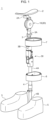
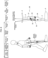
- Fig. 1 illustrates a weight-supported walking assist apparatus 1 according to this embodiment, which has a seat unit 2 supporting a wearer's buttocks, a thigh frame 3 and a lower leg frame 4 which are located along inside of the wearer's leg, and shoe units 5 which are attached to the wearer's right and left foot parts and either of which is joined to the other end 4B of the lower leg frame 4.
- the thigh frame 3 and the lower leg frame 4 have a frame body formed in an elongated plate shape made of, for example, a metal such as stainless steel, carbon fibers (carbon fibers), or the like and are made to be lightweight and have high rigidity.
- a hip joint connector 10 which is rotatable according to motions of the wearer's hip joint part is connected between a seat clamp 2A fixed on an underside of the seat unit 2 and one end 3A of the thigh frame 3.
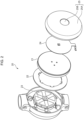
- This hip joint connector 10 has a drive unit (a rotary drive unit) 20 for driving the thigh frame 3 in a rotation direction of the hip joint part relative to the seat unit 2.
- the drive unit 20 has a flat-type actuator 21 consisting of, for example, a brushless DC motor, an actuator control unit 22 for driving and controlling the actuator 21, and a decelerator 23 for converting a rotation speed of a rotator of the actuator 21 to a specified deceleration rate and outputting the converted speed.
- the actuator control unit 22 has a built-in MCM (Multi-Chip Module) in which a CPU (Central Processing Unit), a memory, and so on are mounted.
- MCM Multi-Chip Module
- An operation unit 25 is configured from a touch panel 25A constituting a surface of a housing and a power button 25B in the center of the housing, the operation content to the touch panel 25A by the wearer's fingertip contact is reflected in the actuator control unit 22 as a detection result of a touch sensor 24, and the power is turned on or off in response to pressing down of the power button 25B.
- a main body of the decelerator 23 and the actuator control unit 22 are housed in substantially the same plane in the seat clamp 2Afixed on the underside of the seat unit 2, and an output axis of the decelerator 23 is fixed to one end 3A of the thigh frame 3.
- a knee joint connector 30 which is rotatable according to motions of the wearer's knee joint part is connected between the other end 3B of the thigh frame 3 and one end 4A of the lower leg frame 4.
- the knee joint connector 30 has a closed-loop structure consisting of a four-link mechanism of a fixed link, a driver, a follower, and an intermediate link, and the follower is made to rotate via the intermediate link according to rotations of the driver with reference to the fixed link.
- a thigh-side link unit 31 connected to the other end 3B of the thigh frame 3 is provided with rotation axes R1 and R2 on the center and rear sides respectively to form a fixed link, one end 33A of a bending link unit 32 which is a driver is connected to the rear rotation axis R1, and one end 33A of a patella link unit 33 which is a follower is connected to the center rotation axis R2.
- the lower-leg-side link unit 34 connected to one end 4A of the lower leg frame 4 is provided with rotation axes R3 and R4 on the front and rear sides, respectively, to form an intermediate link, the other end 33B of the patella link unit 33 is connected to the front rotation axis R3, and the other end 32B of the bending link unit 32 is connected to the rear rotation axis R4.
- a connection site between one end 4A of the lower leg frame 4 and the other end 32B of the bending link unit 32 is provided with a lock mechanism unit 35 centered at a corresponding rotation axis R5, and a rotating state of the lower leg frame 4 and the bending link unit 32 is locked or released according to the operation of an electromagnetic solenoid.
- each of the thigh frame 3 and the lower leg frame 4 has a built-in adjustment mechanism unit (which is not illustrated in the drawing) for adjusting its frame length in a stretchable manner.
- the shoe unit(s) 5 attached to the wearer's foot part(s), which is an object to be treated, is connected to the other end 4B of the lower leg frame 4.
- the shoe unit 5 has a short shoe wrapping the wearer's foot part and a fixed fastening unit (which is not illustrated in the drawing) consisting of a metal component which is relatively highly rigid and is joined to an inside surface of the short shoe.
- Cuffs 7 and 8 are attached to the thigh frame 3 and the lower leg frame 4, respectively ( Fig. 1 ), so that they wrap around the wearer's thigh part and lower leg part, respectively, and fasten them firmly.
- the weight-supported walking assist apparatus 1 when the wearer performs the walking motions with their buttocks supported by the seat unit 2, it becomes possible to reduce the load on the knee joint part, which is imposed by the wearer's own weight, during the stance phase of the walking motions.
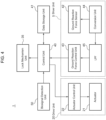
- Fig. 4 illustrates the configuration of a control system for the weight-supported walking assist apparatus 1 according to this embodiment.
- the control system has a control unit 40 for implementing overall control of the entire system and a data storage unit 41.
- the soles of the right and left shoe units 5 are provided with an insole-type ground reaction force sensor 42 to detect a reaction force (pressure distribution to the foot sole parts) against the load applied to the wearer's foot sole surface.
- the ground reaction force sensor 42 can divide the load applied to the foot sole surface into a front foot part (toe part) and a rear foot part (heel part) and measure the divided loads independently.
- This ground reaction force sensor 42 consisting of, for example, a piezoelectric element that outputs a voltage according to the applied load or a sensor whose static capacitance changes according to the load and can detect load changes associated with weight movements and whether the wearer's leg is in contact with the ground or not, respectively.
- the shoe unit 5 has a ground reaction force control unit 43 consisting of a ground reaction force sensor 42 and an MCU (Micro Control Unit) other than the shoe structure. After the output of the ground reaction force sensor 42 is converted into voltage via a conversion unit 44, a high-frequency band is cut off via an LPF (Low Pass Filter) 45 and the obtained voltage is then input to the ground reaction force control unit 43.
- a ground reaction force control unit 43 consisting of a ground reaction force sensor 42 and an MCU (Micro Control Unit) other than the shoe structure.
- this ground reaction force control unit 43 Based on the detection result of the ground reaction force sensor 42, this ground reaction force control unit 43 checks whether or not any load change or any contact with the ground has been caused by the wearer's weight movements, and sends the result as ground reaction force data to the control unit 40.
- the control unit 40 stores the received ground reaction force data in a reference parameter database of the data storage unit 41.
- the control unit 40 as a walking synchronization calculation unit calculates the wearer's gait cycle on the basis of the detection result of the ground reaction force sensor 42. Specifically, the control unit 40 identifies the relevant phase of the wearer's walking motions by comparing a load transition state relating to the foot soles based on the ground reaction force data and a load transition state of reference parameters stored in the reference parameter database of the data storage unit 41.
- the control unit 40 captures the identified phase of the walking motions by dividing the walking state into a swing phase and a stance phase.
- the swing phase is a phase of movement in which a foot leaves the ground and swings out the lower leg.
- the stance phase is a phase in which the foot contacts the ground and supports the wearer's own weight.
- the ground reaction force on the rear foot part side increases in advance of the ground reaction force on the front foot part side (toe part side).
- the rear foot part of the foot part leaves the ground first and then the front foot part leaves the ground. So, the ground reaction force on the front foot part side decreases after the ground reaction force on the rear foot part side.
- the control unit 40 judges the relevant phase based on information about the ground reaction force on the front foot part side and the ground reaction force on the rear foot part side (ground reaction force data representing the load) in the shoe sole part.
- the ground reaction force on the rear foot part side increases, it is determined that the swing phase switches to the stance phase; and when the ground reaction force on the front foot part side decreases, it is determined that the stance phase switches to the swing phase.
- control unit 40 locks or releases the rotational state of the lower-leg-side link unit 34 and the bending link unit 32 by controlling the electromagnetic solenoid of the lock mechanism unit 35 on the basis of the calculation result of walking synchronization.
- control unit 40 controls the lock mechanism unit 35 and locks the rotary state of the bending link unit 32 in the bending direction with respect to the lower-leg-side link unit 34 to limit the bending of the wearer's knee joint part to a specified range ( Fig. 5(A) ).
- the control unit 40 controls the lock mechanism unit 35 and releases the rotary state of the bending link unit 32 in the bending direction with respect to the lower-leg-side link unit 34 ( Fig. 5(B) ).
- the bending link unit 32, the patella link unit 33, and the lower-leg-side link unit 34 become rotatable relative to the thigh-side link unit 31 so that the wearer's knee joint part can bend or extend ( Fig. 5(C) ).
- a biosignal detection unit 50 ( Fig. 4 ) is attached to the wearer's thigh part on the side where the thigh frame is located to detect a biosignal caused by the wearer's walking motions.
- control unit 40 causes the drive unit (rotary drive unit) 20 to generate motive power according to the wearer's intention upon the transition from the stance phase to the swing phase on the basis of the detection result of the biosignal detection unit 50.
- the actuator control unit 22 of the drive unit 20 can transmit a driving torque of the actuator 21 according to movements of the wearer's hip joint as an assist force to the hip joint by driving and controlling the actuator 21 based on the detection result of the biosignal detection unit 50 sent from the control unit 40.
- the control unit 40 locks the lock mechanism unit 35 of the knee joint connector 30 in a beginning part of the stance phase of the walking motions (from an initial contact to a loading response phase) ( Fig. 6 ).
- the lock mechanism unit 35 of the knee joint connector 30 is locked so that a line of action F1 of the ground reaction force obtained from the foot sole surface of the wearer's shoe unit is positioned ahead of an instantaneous center (center point when a mass point moving on an arbitrary curve performs rotational motions about a given point far center at a given moment) P1 between the thigh-side link unit (fixed link) 31 and the lower-leg-side link unit (intermediate link) 34.
- the control unit 40 releases the lock mechanism unit 35 of the knee joint connector 30 in a middle part of the stance phase (from a mid-stance phase to a terminal stance phase).
- the line of action F1 of the ground reaction force obtained from the foot sole surface of the wearer's shoe unit 5 is inclined slightly backwards from the vertical direction, the position of the instantaneous center P1 between the thigh-side link unit 31 and the lower-leg-side link unit 34 moves backwards and upwards, thereby increasing the stability of the support for the wearer's body weight.
- the thigh-side link unit 31 starts to bend relative to the lower-leg-side link unit 34 in an ending part of the stance phase (from the terminal stance phase to a pre-swing phase).
- the line of action F1 of the ground reaction force obtained from the foot sole surface of the wearer's shoe unit moves behind the position of the instantaneous center P1 between the thigh-side link unit 31 and the lower-leg-side link unit 34.
- the control unit 40 releases the lock mechanism unit 35 so that the wearer's knee joint part can bend or extend upon the transition from the stance phase to the swing phase, as illustrated in Figs. 6 to 8 as explained earlier.
- control unit 40 causes the drive unit (rotary drive unit) 20 to generate the motive power according to the wearer's intention upon the transition from the stance phase to the swing phase on the basis of the detection result of the biosignal detection unit 50.
- the motions can be assisted while reducing the load on the knee joint part, which is imposed by the wearer's own weight, by reducing the ground reaction force during the stance phase of the walking motions.
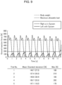
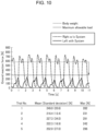
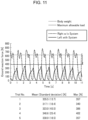
- walking training is firstly performed by applying a load of 1/3 of the wearer's total body weight to the wearer's lower limb and then the load amount is increased according to a state of cell colonization. So, the walking motions were checked when the load applied to the wearer's lower limb on the wearing side was set to a 1/3 ( Fig. 9 ), a 1/2 ( Fig. 10 ), and 2 / 3 ( Fig. 11 ) of the wearer's total body weight, respectively.
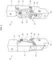
- this embodiment has described as explained earlier the case where the knee joint connector having the closed-loop structure consisting of the four-link mechanism is applied to the weight-supported walking assist apparatus 1; however, the present invention is not limited to this example and a weight-supported walking assist apparatus 61 having a knee joint connector 60 of a joint structure with a lock mechanism as illustrated in Fig. 12 , in which the same reference numerals as those in Fig. 1 are assigned to parts corresponding to those in Fig. 1 , may be applied.
- Fig. 13(B) illustrates an internal structure of the knee joint connector 60.
- a protrusion 71Y of the thigh-side part unit 71 fits, in a freely movable manner, in a recess 70X in the lower-leg-side part unit 70 and they engage with each other in such a manner that a pin PN formed on the protrusion 71Y can slide and move along a slide hole SH ( Fig. 13(A)) formed in the recess 70X.
- a locking protrusion 70XZ is formed at an end of the recess 70X in the lower-leg-side part unit 70; and as a root part of the protrusion 71Y of the thigh-side part unit 71 enters into contact with the locking protrusion 70XZ, movability in its contact direction becomes impossible and is thereby limited. Under this circumstance, it is designed as illustrated in Fig. 14(B) so that the pin PN of the thigh-side part unit 71 enters into contact with a lower end of the slide hole SH in the lower-leg-side part unit 70.
- the thigh-side part unit 71 can rotate in bending directions relative to the lower-leg-side part unit 70 (rotational directions indicated with arrows B) as illustrated in Fig.
- the control unit 40 causes the stopper ST of the lock mechanism unit 72 to be positioned at the upper end in the beginning part of the stance phase of the walking motions (from the initial contact to the loading response phase), thereby limiting the bending state of the knee joint connector 60 and preventing the wearer's knee buckling.
- the root part of the protrusion 71Y of the thigh-side part unit 71 enters into contact with the locking protrusion 70XZ in the recess 70X in the lower-leg-side part unit 70, thereby making it possible for the knee joint connector 60 to enter into an extended state and stably support the wearer's body weight.
- the control unit causes the stopper ST of the lock mechanism unit 72 to be positioned at the lower end, so that the thigh frame 3 starts to bend relative to the lower leg frame 4.
- the control unit 40 causes the stopper ST of the lock mechanism unit 72 to be positioned at the upper end so as to limit bending of the wearer's knee joint part to a specified range and thereby fixes the rotary state; and after that, upon the transition from the stance phase to the swing phase, the control unit 40 causes the stopper ST of the lock mechanism unit 72 to be positioned at the lower end so that the wearer's knee joint part can bend or extend.
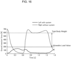
- Fig. 16 illustrates the relationship between a load value of one gait cycle by the wearer and movement control of the stopper ST of the lock mechanism unit 72.
- this embodiment has described the case where the insole-type ground reaction force sensor 42 is provided at soles of the right and left shoe units 5 and the reaction force to the load imposed on the wearer's foot sole surfaces (pressure distribution to the foot sole parts) is detected; however, the present invention is not limited to this example and, in addition to the ground reaction force sensor 42, a seat surface reaction force sensor (which is not illustrated in the drawing) may be also provided at the seat unit.
- the seat surface reaction force sensor which is mounted in the seat unit and detects the pressure distribution to the wearer's buttocks is further included and the control unit 40 controls the drive unit (rotation drive unit) 20 to cause the shoe unit to not contact the walking surface during the swing phase of the walking motions on the basis of the detection result of the biosignal detection unit 50 and the detection result of the seat surface reaction force sensor.
- the weight-supported walking assist apparatus 1 can assist the motions by adjusting the weight burden on the knee joint part, which is imposed by the wearer's own weight, to the optimum state with high accuracy by reducing the ground reaction force during the stance phase of the walking motions on the basis of not only the pressure distribution to the wearer's foot sole parts, but also the pressure distribution to the wearer's buttocks.
Landscapes
- Health & Medical Sciences (AREA)
- Epidemiology (AREA)
- Pain & Pain Management (AREA)
- Physical Education & Sports Medicine (AREA)
- Rehabilitation Therapy (AREA)
- Life Sciences & Earth Sciences (AREA)
- Animal Behavior & Ethology (AREA)
- General Health & Medical Sciences (AREA)
- Public Health (AREA)
- Veterinary Medicine (AREA)
- Rehabilitation Tools (AREA)
- Manipulator (AREA)
Applications Claiming Priority (2)
| Application Number | Priority Date | Filing Date | Title |
|---|---|---|---|
| JP2021153401A JP7668710B2 (ja) | 2021-09-21 | 2021-09-21 | 体重支援型歩行補助装置およびその作動方法 |
| PCT/JP2022/029215 WO2023047798A1 (ja) | 2021-09-21 | 2022-07-28 | 体重支援型歩行補助装置およびその制御方法 |
Publications (3)
| Publication Number | Publication Date |
|---|---|
| EP4406525A1 true EP4406525A1 (de) | 2024-07-31 |
| EP4406525A4 EP4406525A4 (de) | 2025-08-27 |
| EP4406525B1 EP4406525B1 (de) | 2026-01-21 |
Family
ID=85719400
Family Applications (1)
| Application Number | Title | Priority Date | Filing Date |
|---|---|---|---|
| EP22872554.5A Active EP4406525B1 (de) | 2021-09-21 | 2022-07-28 | Gehhilfevorrichtung mit körpergewichtunterstützung und verfahren zur steuerung davon |
Country Status (4)
| Country | Link |
|---|---|
| US (1) | US20240390211A1 (de) |
| EP (1) | EP4406525B1 (de) |
| JP (1) | JP7668710B2 (de) |
| WO (1) | WO2023047798A1 (de) |
Families Citing this family (1)
| Publication number | Priority date | Publication date | Assignee | Title |
|---|---|---|---|---|
| WO2023140491A1 (en) * | 2022-01-19 | 2023-07-27 | Bnr Co., Ltd. | Gait rehabilitation device |
Family Cites Families (8)
| Publication number | Priority date | Publication date | Assignee | Title |
|---|---|---|---|---|
| US6966882B2 (en) | 2002-11-25 | 2005-11-22 | Tibion Corporation | Active muscle assistance device and method |
| US7578799B2 (en) * | 2006-06-30 | 2009-08-25 | Ossur Hf | Intelligent orthosis |
| JP4712627B2 (ja) * | 2006-07-10 | 2011-06-29 | 本田技研工業株式会社 | 歩行補助装置 |
| JP5697947B2 (ja) | 2010-10-28 | 2015-04-08 | パナソニック株式会社 | 下肢動作支援装置 |
| CN103200919B (zh) * | 2010-11-24 | 2015-04-22 | 川崎重工业株式会社 | 佩戴型动作支援装置 |
| JP2013135804A (ja) | 2011-12-28 | 2013-07-11 | Toyota Motor Corp | 歩行補助装置 |
| US11766350B2 (en) | 2017-10-10 | 2023-09-26 | The Regents Of The University Of California | Method and apparatus for a passive knee joint |
| JP2021029266A (ja) | 2019-08-13 | 2021-03-01 | Cyberdyne株式会社 | 体重支援型歩行補助装置およびその制御方法 |
-
2021
- 2021-09-21 JP JP2021153401A patent/JP7668710B2/ja active Active
-
2022
- 2022-07-28 WO PCT/JP2022/029215 patent/WO2023047798A1/ja not_active Ceased
- 2022-07-28 EP EP22872554.5A patent/EP4406525B1/de active Active
- 2022-07-28 US US18/694,097 patent/US20240390211A1/en active Pending
Also Published As
| Publication number | Publication date |
|---|---|
| US20240390211A1 (en) | 2024-11-28 |
| EP4406525B1 (de) | 2026-01-21 |
| WO2023047798A1 (ja) | 2023-03-30 |
| JP2023045150A (ja) | 2023-04-03 |
| EP4406525A4 (de) | 2025-08-27 |
| JP7668710B2 (ja) | 2025-04-25 |
Similar Documents
| Publication | Publication Date | Title |
|---|---|---|
| Ha et al. | Volitional control of a prosthetic knee using surface electromyography | |
| Detrembleur et al. | Relationship between energy cost, gait speed, vertical displacement of centre of body mass and efficiency of pendulum-like mechanism in unilateral amputee gait | |
| CN105722490B (zh) | 用于来自下肢矫形器的通信的人机接口 | |
| KR101112119B1 (ko) | 무릎보조기 | |
| CN110051503A (zh) | 一种基于人体下肢外骨骼的(康复)机器人 | |
| Elery et al. | Effects of a powered knee-ankle prosthesis on amputee hip compensations: A case series | |
| US20240156665A1 (en) | Orthopaedic technical device and method for controlling same | |
| EP3079581A2 (de) | Unterstützende flexible anzüge, flexible anzugsysteme und verfahren zur herstellung und steuerung davon zur unterstützung der menschlichen mobilität | |
| US20150005686A1 (en) | Knee Orthosis Device and Associated Methods | |
| Catani et al. | Gait analysis in patients after Van Nes rotationplasty | |
| To et al. | Sensor-based hip control with hybrid neuroprosthesis for walking in paraplegia. | |
| EP3439585B1 (de) | Polyzentrische angetriebene knöchelprothese | |
| EP4406525B1 (de) | Gehhilfevorrichtung mit körpergewichtunterstützung und verfahren zur steuerung davon | |
| Lenzi et al. | Preliminary evaluation of a new control approach to achieve speed adaptation in robotic transfemoral prostheses | |
| US20250064663A1 (en) | Ankle exoskeleton device | |
| Zhou et al. | Preliminary evaluation of gait assistance during treadmill walking with a light-weight bionic knee exoskeleton | |
| Martini et al. | Lower-limb amputees can reduce the energy cost of walking when assisted by an Active Pelvis Orthosis | |
| US20100263233A1 (en) | Rocker shoes for prescribed ankle motion | |
| Meadows et al. | Biomechanics of the hip, knee and ankle | |
| Sanz-Morère et al. | A bioinspired control strategy for the CYBERLEGs knee-ankle-foot orthosis: feasibility study with lower-limb amputees | |
| JP2021029266A (ja) | 体重支援型歩行補助装置およびその制御方法 | |
| Kempfer et al. | Prosthetic and orthotic devices | |
| KR102734254B1 (ko) | 하지 보조로봇의 제어방법 | |
| LaPrè et al. | A control strategy for an active alignment transtibial prosthesis | |
| Gloger et al. | Active lower limb orthosis with one degree of freedom for people with paraplegia |
Legal Events
| Date | Code | Title | Description |
|---|---|---|---|
| STAA | Information on the status of an ep patent application or granted ep patent |
Free format text: STATUS: THE INTERNATIONAL PUBLICATION HAS BEEN MADE |
|
| PUAI | Public reference made under article 153(3) epc to a published international application that has entered the european phase |
Free format text: ORIGINAL CODE: 0009012 |
|
| STAA | Information on the status of an ep patent application or granted ep patent |
Free format text: STATUS: REQUEST FOR EXAMINATION WAS MADE |
|
| 17P | Request for examination filed |
Effective date: 20240417 |
|
| AK | Designated contracting states |
Kind code of ref document: A1 Designated state(s): AL AT BE BG CH CY CZ DE DK EE ES FI FR GB GR HR HU IE IS IT LI LT LU LV MC MK MT NL NO PL PT RO RS SE SI SK SM TR |
|
| DAV | Request for validation of the european patent (deleted) | ||
| DAX | Request for extension of the european patent (deleted) | ||
| A4 | Supplementary search report drawn up and despatched |
Effective date: 20250730 |
|
| RIC1 | Information provided on ipc code assigned before grant |
Ipc: A61H 3/00 20060101AFI20250724BHEP |
|
| GRAP | Despatch of communication of intention to grant a patent |
Free format text: ORIGINAL CODE: EPIDOSNIGR1 |
|
| STAA | Information on the status of an ep patent application or granted ep patent |
Free format text: STATUS: GRANT OF PATENT IS INTENDED |
|
| INTG | Intention to grant announced |
Effective date: 20251017 |
|
| GRAS | Grant fee paid |
Free format text: ORIGINAL CODE: EPIDOSNIGR3 |
|
| GRAA | (expected) grant |
Free format text: ORIGINAL CODE: 0009210 |
|
| STAA | Information on the status of an ep patent application or granted ep patent |
Free format text: STATUS: THE PATENT HAS BEEN GRANTED |
|
| AK | Designated contracting states |
Kind code of ref document: B1 Designated state(s): AL AT BE BG CH CY CZ DE DK EE ES FI FR GB GR HR HU IE IS IT LI LT LU LV MC MK MT NL NO PL PT RO RS SE SI SK SM TR |
|
| REG | Reference to a national code |
Ref country code: CH Ref legal event code: F10 Free format text: ST27 STATUS EVENT CODE: U-0-0-F10-F00 (AS PROVIDED BY THE NATIONAL OFFICE) Effective date: 20260121 |
|
| REG | Reference to a national code |
Ref country code: DE Ref legal event code: R096 Ref document number: 602022029001 Country of ref document: DE |
|
| REG | Reference to a national code |
Ref country code: IE Ref legal event code: FG4D |