EP4406510A2 - Implantat zur behandlung und/oder zum ersatz einer entzündeten, thrombosierten oder degenerierten herzklappe - Google Patents
Implantat zur behandlung und/oder zum ersatz einer entzündeten, thrombosierten oder degenerierten herzklappe Download PDFInfo
- Publication number
- EP4406510A2 EP4406510A2 EP24165540.6A EP24165540A EP4406510A2 EP 4406510 A2 EP4406510 A2 EP 4406510A2 EP 24165540 A EP24165540 A EP 24165540A EP 4406510 A2 EP4406510 A2 EP 4406510A2
- Authority
- EP
- European Patent Office
- Prior art keywords
- implant
- heart valve
- capture device
- designed
- implanted
- Prior art date
- Legal status (The legal status is an assumption and is not a legal conclusion. Google has not performed a legal analysis and makes no representation as to the accuracy of the status listed.)
- Pending
Links
- 210000003709 heart valve Anatomy 0.000 title claims abstract description 255
- 239000007943 implant Substances 0.000 title claims abstract description 191
- 238000002513 implantation Methods 0.000 claims abstract description 49
- 206010061218 Inflammation Diseases 0.000 claims abstract description 16
- 230000004054 inflammatory process Effects 0.000 claims abstract description 16
- 208000015181 infectious disease Diseases 0.000 claims abstract description 9
- 230000008859 change Effects 0.000 claims abstract description 3
- 238000004873 anchoring Methods 0.000 claims description 29
- 239000013543 active substance Substances 0.000 claims description 23
- 238000000576 coating method Methods 0.000 claims description 12
- 239000011248 coating agent Substances 0.000 claims description 11
- 230000000845 anti-microbial effect Effects 0.000 claims description 10
- 239000003146 anticoagulant agent Substances 0.000 claims description 10
- 239000004480 active ingredient Substances 0.000 claims description 8
- 230000002785 anti-thrombosis Effects 0.000 claims description 7
- 239000004599 antimicrobial Substances 0.000 claims description 7
- 230000017531 blood circulation Effects 0.000 claims description 7
- 230000010261 cell growth Effects 0.000 claims description 5
- 230000002401 inhibitory effect Effects 0.000 claims description 5
- 239000000463 material Substances 0.000 claims description 5
- 239000002861 polymer material Substances 0.000 claims description 5
- 230000000844 anti-bacterial effect Effects 0.000 claims description 4
- 239000012528 membrane Substances 0.000 claims description 4
- 229920001410 Microfiber Polymers 0.000 claims description 2
- 230000003115 biocidal effect Effects 0.000 claims description 2
- 238000005538 encapsulation Methods 0.000 claims description 2
- 239000004744 fabric Substances 0.000 claims description 2
- 239000003658 microfiber Substances 0.000 claims description 2
- 230000002537 thrombolytic effect Effects 0.000 claims description 2
- 239000003795 chemical substances by application Substances 0.000 claims 1
- 210000001519 tissue Anatomy 0.000 description 35
- 238000000034 method Methods 0.000 description 32
- 210000002216 heart Anatomy 0.000 description 27
- 206010014665 endocarditis Diseases 0.000 description 26
- 210000001765 aortic valve Anatomy 0.000 description 24
- 238000003780 insertion Methods 0.000 description 14
- 230000037431 insertion Effects 0.000 description 14
- 210000000709 aorta Anatomy 0.000 description 12
- 239000008280 blood Substances 0.000 description 10
- 210000004369 blood Anatomy 0.000 description 10
- 230000006870 function Effects 0.000 description 9
- 229910001000 nickel titanium Inorganic materials 0.000 description 7
- HLXZNVUGXRDIFK-UHFFFAOYSA-N nickel titanium Chemical compound [Ti].[Ti].[Ti].[Ti].[Ti].[Ti].[Ti].[Ti].[Ti].[Ti].[Ti].[Ni].[Ni].[Ni].[Ni].[Ni].[Ni].[Ni].[Ni].[Ni].[Ni].[Ni].[Ni].[Ni].[Ni] HLXZNVUGXRDIFK-UHFFFAOYSA-N 0.000 description 7
- 210000005240 left ventricle Anatomy 0.000 description 6
- 208000007536 Thrombosis Diseases 0.000 description 5
- 230000001580 bacterial effect Effects 0.000 description 5
- 230000008901 benefit Effects 0.000 description 5
- 210000004351 coronary vessel Anatomy 0.000 description 5
- 238000011065 in-situ storage Methods 0.000 description 5
- 230000014759 maintenance of location Effects 0.000 description 5
- 230000007850 degeneration Effects 0.000 description 4
- 239000003814 drug Substances 0.000 description 4
- 229940079593 drug Drugs 0.000 description 4
- 210000001174 endocardium Anatomy 0.000 description 4
- 201000007119 infective endocarditis Diseases 0.000 description 4
- 239000000126 substance Substances 0.000 description 4
- 238000001356 surgical procedure Methods 0.000 description 4
- 239000000560 biocompatible material Substances 0.000 description 3
- 239000012876 carrier material Substances 0.000 description 3
- 238000013461 design Methods 0.000 description 3
- 201000010099 disease Diseases 0.000 description 3
- 208000037265 diseases, disorders, signs and symptoms Diseases 0.000 description 3
- 210000003734 kidney Anatomy 0.000 description 3
- 210000004072 lung Anatomy 0.000 description 3
- 210000004115 mitral valve Anatomy 0.000 description 3
- 210000000056 organ Anatomy 0.000 description 3
- 210000003102 pulmonary valve Anatomy 0.000 description 3
- 210000000591 tricuspid valve Anatomy 0.000 description 3
- 208000031729 Bacteremia Diseases 0.000 description 2
- 241000894006 Bacteria Species 0.000 description 2
- CURLTUGMZLYLDI-UHFFFAOYSA-N Carbon dioxide Chemical compound O=C=O CURLTUGMZLYLDI-UHFFFAOYSA-N 0.000 description 2
- 206010040070 Septic Shock Diseases 0.000 description 2
- 241000295644 Staphylococcaceae Species 0.000 description 2
- 230000036760 body temperature Effects 0.000 description 2
- 210000004556 brain Anatomy 0.000 description 2
- 230000007797 corrosion Effects 0.000 description 2
- 238000005260 corrosion Methods 0.000 description 2
- 238000011161 development Methods 0.000 description 2
- 230000018109 developmental process Effects 0.000 description 2
- 238000009826 distribution Methods 0.000 description 2
- 238000005516 engineering process Methods 0.000 description 2
- 239000007789 gas Substances 0.000 description 2
- 206010020718 hyperplasia Diseases 0.000 description 2
- 230000002390 hyperplastic effect Effects 0.000 description 2
- 239000007788 liquid Substances 0.000 description 2
- 230000007246 mechanism Effects 0.000 description 2
- 230000003446 memory effect Effects 0.000 description 2
- 244000005700 microbiome Species 0.000 description 2
- 230000000737 periodic effect Effects 0.000 description 2
- 210000001147 pulmonary artery Anatomy 0.000 description 2
- 210000005241 right ventricle Anatomy 0.000 description 2
- 229910001285 shape-memory alloy Inorganic materials 0.000 description 2
- 239000000243 solution Substances 0.000 description 2
- 241000894007 species Species 0.000 description 2
- 238000012546 transfer Methods 0.000 description 2
- 230000007704 transition Effects 0.000 description 2
- TVEXGJYMHHTVKP-UHFFFAOYSA-N 6-oxabicyclo[3.2.1]oct-3-en-7-one Chemical compound C1C2C(=O)OC1C=CC2 TVEXGJYMHHTVKP-UHFFFAOYSA-N 0.000 description 1
- 208000027896 Aortic valve disease Diseases 0.000 description 1
- 206010002915 Aortic valve incompetence Diseases 0.000 description 1
- 208000034309 Bacterial disease carrier Diseases 0.000 description 1
- 241000283690 Bos taurus Species 0.000 description 1
- 208000005189 Embolism Diseases 0.000 description 1
- 206010014666 Endocarditis bacterial Diseases 0.000 description 1
- 206010019280 Heart failures Diseases 0.000 description 1
- 206010053159 Organ failure Diseases 0.000 description 1
- 229920000954 Polyglycolide Polymers 0.000 description 1
- 206010040047 Sepsis Diseases 0.000 description 1
- 206010044248 Toxic shock syndrome Diseases 0.000 description 1
- 231100000650 Toxic shock syndrome Toxicity 0.000 description 1
- 206010000269 abscess Diseases 0.000 description 1
- 230000004913 activation Effects 0.000 description 1
- 230000001154 acute effect Effects 0.000 description 1
- 210000003484 anatomy Anatomy 0.000 description 1
- 229940127219 anticoagulant drug Drugs 0.000 description 1
- 201000002064 aortic valve insufficiency Diseases 0.000 description 1
- 210000001367 artery Anatomy 0.000 description 1
- QVGXLLKOCUKJST-UHFFFAOYSA-N atomic oxygen Chemical compound [O] QVGXLLKOCUKJST-UHFFFAOYSA-N 0.000 description 1
- 208000009361 bacterial endocarditis Diseases 0.000 description 1
- 244000052616 bacterial pathogen Species 0.000 description 1
- 239000003899 bactericide agent Substances 0.000 description 1
- 239000012620 biological material Substances 0.000 description 1
- 210000004204 blood vessel Anatomy 0.000 description 1
- 229910002092 carbon dioxide Inorganic materials 0.000 description 1
- 239000001569 carbon dioxide Substances 0.000 description 1
- 238000007675 cardiac surgery Methods 0.000 description 1
- 239000008148 cardioplegic solution Substances 0.000 description 1
- 239000000969 carrier Substances 0.000 description 1
- 238000005234 chemical deposition Methods 0.000 description 1
- 238000007385 chemical modification Methods 0.000 description 1
- 230000001427 coherent effect Effects 0.000 description 1
- 150000001875 compounds Chemical class 0.000 description 1
- 230000006835 compression Effects 0.000 description 1
- 238000007906 compression Methods 0.000 description 1
- 230000008828 contractile function Effects 0.000 description 1
- 231100000433 cytotoxic Toxicity 0.000 description 1
- 230000001472 cytotoxic effect Effects 0.000 description 1
- 230000006735 deficit Effects 0.000 description 1
- 238000006073 displacement reaction Methods 0.000 description 1
- 230000009977 dual effect Effects 0.000 description 1
- 230000010102 embolization Effects 0.000 description 1
- 210000003038 endothelium Anatomy 0.000 description 1
- 210000002837 heart atrium Anatomy 0.000 description 1
- 208000021760 high fever Diseases 0.000 description 1
- 244000052637 human pathogen Species 0.000 description 1
- 210000005246 left atrium Anatomy 0.000 description 1
- 210000004185 liver Anatomy 0.000 description 1
- 210000002418 meninge Anatomy 0.000 description 1
- 230000002503 metabolic effect Effects 0.000 description 1
- 239000002184 metal Substances 0.000 description 1
- 239000004745 nonwoven fabric Substances 0.000 description 1
- 229910052760 oxygen Inorganic materials 0.000 description 1
- 239000001301 oxygen Substances 0.000 description 1
- 238000005289 physical deposition Methods 0.000 description 1
- 231100000614 poison Toxicity 0.000 description 1
- 230000007096 poisonous effect Effects 0.000 description 1
- 229920000747 poly(lactic acid) Polymers 0.000 description 1
- 229920002463 poly(p-dioxanone) polymer Polymers 0.000 description 1
- 239000000622 polydioxanone Substances 0.000 description 1
- 229920000151 polyglycol Polymers 0.000 description 1
- 239000010695 polyglycol Substances 0.000 description 1
- -1 polylactones Polymers 0.000 description 1
- 229920000642 polymer Polymers 0.000 description 1
- 230000008569 process Effects 0.000 description 1
- 230000002685 pulmonary effect Effects 0.000 description 1
- 238000005086 pumping Methods 0.000 description 1
- 230000004044 response Effects 0.000 description 1
- 210000005245 right atrium Anatomy 0.000 description 1
- 238000004904 shortening Methods 0.000 description 1
- 210000003491 skin Anatomy 0.000 description 1
- 238000003860 storage Methods 0.000 description 1
- 230000009885 systemic effect Effects 0.000 description 1
- 230000001732 thrombotic effect Effects 0.000 description 1
- 231100000167 toxic agent Toxicity 0.000 description 1
- 239000003440 toxic substance Substances 0.000 description 1
- 238000002604 ultrasonography Methods 0.000 description 1
- 230000002792 vascular Effects 0.000 description 1
- 210000003462 vein Anatomy 0.000 description 1
Images


Classifications
-
- A—HUMAN NECESSITIES
- A61—MEDICAL OR VETERINARY SCIENCE; HYGIENE
- A61F—FILTERS IMPLANTABLE INTO BLOOD VESSELS; PROSTHESES; DEVICES PROVIDING PATENCY TO, OR PREVENTING COLLAPSING OF, TUBULAR STRUCTURES OF THE BODY, e.g. STENTS; ORTHOPAEDIC, NURSING OR CONTRACEPTIVE DEVICES; FOMENTATION; TREATMENT OR PROTECTION OF EYES OR EARS; BANDAGES, DRESSINGS OR ABSORBENT PADS; FIRST-AID KITS
- A61F2/00—Filters implantable into blood vessels; Prostheses, i.e. artificial substitutes or replacements for parts of the body; Appliances for connecting them with the body; Devices providing patency to, or preventing collapsing of, tubular structures of the body, e.g. stents
- A61F2/02—Prostheses implantable into the body
- A61F2/24—Heart valves ; Vascular valves, e.g. venous valves; Heart implants, e.g. passive devices for improving the function of the native valve or the heart muscle; Transmyocardial revascularisation [TMR] devices; Valves implantable in the body
- A61F2/2412—Heart valves ; Vascular valves, e.g. venous valves; Heart implants, e.g. passive devices for improving the function of the native valve or the heart muscle; Transmyocardial revascularisation [TMR] devices; Valves implantable in the body with soft flexible valve members, e.g. tissue valves shaped like natural valves
- A61F2/2418—Scaffolds therefor, e.g. support stents
-
- A—HUMAN NECESSITIES
- A61—MEDICAL OR VETERINARY SCIENCE; HYGIENE
- A61F—FILTERS IMPLANTABLE INTO BLOOD VESSELS; PROSTHESES; DEVICES PROVIDING PATENCY TO, OR PREVENTING COLLAPSING OF, TUBULAR STRUCTURES OF THE BODY, e.g. STENTS; ORTHOPAEDIC, NURSING OR CONTRACEPTIVE DEVICES; FOMENTATION; TREATMENT OR PROTECTION OF EYES OR EARS; BANDAGES, DRESSINGS OR ABSORBENT PADS; FIRST-AID KITS
- A61F2/00—Filters implantable into blood vessels; Prostheses, i.e. artificial substitutes or replacements for parts of the body; Appliances for connecting them with the body; Devices providing patency to, or preventing collapsing of, tubular structures of the body, e.g. stents
- A61F2/02—Prostheses implantable into the body
- A61F2/24—Heart valves ; Vascular valves, e.g. venous valves; Heart implants, e.g. passive devices for improving the function of the native valve or the heart muscle; Transmyocardial revascularisation [TMR] devices; Valves implantable in the body
- A61F2/2442—Annuloplasty rings or inserts for correcting the valve shape; Implants for improving the function of a native heart valve
-
- A—HUMAN NECESSITIES
- A61—MEDICAL OR VETERINARY SCIENCE; HYGIENE
- A61F—FILTERS IMPLANTABLE INTO BLOOD VESSELS; PROSTHESES; DEVICES PROVIDING PATENCY TO, OR PREVENTING COLLAPSING OF, TUBULAR STRUCTURES OF THE BODY, e.g. STENTS; ORTHOPAEDIC, NURSING OR CONTRACEPTIVE DEVICES; FOMENTATION; TREATMENT OR PROTECTION OF EYES OR EARS; BANDAGES, DRESSINGS OR ABSORBENT PADS; FIRST-AID KITS
- A61F2/00—Filters implantable into blood vessels; Prostheses, i.e. artificial substitutes or replacements for parts of the body; Appliances for connecting them with the body; Devices providing patency to, or preventing collapsing of, tubular structures of the body, e.g. stents
- A61F2/0077—Special surfaces of prostheses, e.g. for improving ingrowth
-
- A—HUMAN NECESSITIES
- A61—MEDICAL OR VETERINARY SCIENCE; HYGIENE
- A61F—FILTERS IMPLANTABLE INTO BLOOD VESSELS; PROSTHESES; DEVICES PROVIDING PATENCY TO, OR PREVENTING COLLAPSING OF, TUBULAR STRUCTURES OF THE BODY, e.g. STENTS; ORTHOPAEDIC, NURSING OR CONTRACEPTIVE DEVICES; FOMENTATION; TREATMENT OR PROTECTION OF EYES OR EARS; BANDAGES, DRESSINGS OR ABSORBENT PADS; FIRST-AID KITS
- A61F2/00—Filters implantable into blood vessels; Prostheses, i.e. artificial substitutes or replacements for parts of the body; Appliances for connecting them with the body; Devices providing patency to, or preventing collapsing of, tubular structures of the body, e.g. stents
- A61F2/02—Prostheses implantable into the body
- A61F2/24—Heart valves ; Vascular valves, e.g. venous valves; Heart implants, e.g. passive devices for improving the function of the native valve or the heart muscle; Transmyocardial revascularisation [TMR] devices; Valves implantable in the body
- A61F2/2409—Support rings therefor, e.g. for connecting valves to tissue
-
- A—HUMAN NECESSITIES
- A61—MEDICAL OR VETERINARY SCIENCE; HYGIENE
- A61F—FILTERS IMPLANTABLE INTO BLOOD VESSELS; PROSTHESES; DEVICES PROVIDING PATENCY TO, OR PREVENTING COLLAPSING OF, TUBULAR STRUCTURES OF THE BODY, e.g. STENTS; ORTHOPAEDIC, NURSING OR CONTRACEPTIVE DEVICES; FOMENTATION; TREATMENT OR PROTECTION OF EYES OR EARS; BANDAGES, DRESSINGS OR ABSORBENT PADS; FIRST-AID KITS
- A61F2/00—Filters implantable into blood vessels; Prostheses, i.e. artificial substitutes or replacements for parts of the body; Appliances for connecting them with the body; Devices providing patency to, or preventing collapsing of, tubular structures of the body, e.g. stents
- A61F2/02—Prostheses implantable into the body
- A61F2/24—Heart valves ; Vascular valves, e.g. venous valves; Heart implants, e.g. passive devices for improving the function of the native valve or the heart muscle; Transmyocardial revascularisation [TMR] devices; Valves implantable in the body
- A61F2/2427—Devices for manipulating or deploying heart valves during implantation
-
- A—HUMAN NECESSITIES
- A61—MEDICAL OR VETERINARY SCIENCE; HYGIENE
- A61F—FILTERS IMPLANTABLE INTO BLOOD VESSELS; PROSTHESES; DEVICES PROVIDING PATENCY TO, OR PREVENTING COLLAPSING OF, TUBULAR STRUCTURES OF THE BODY, e.g. STENTS; ORTHOPAEDIC, NURSING OR CONTRACEPTIVE DEVICES; FOMENTATION; TREATMENT OR PROTECTION OF EYES OR EARS; BANDAGES, DRESSINGS OR ABSORBENT PADS; FIRST-AID KITS
- A61F2/00—Filters implantable into blood vessels; Prostheses, i.e. artificial substitutes or replacements for parts of the body; Appliances for connecting them with the body; Devices providing patency to, or preventing collapsing of, tubular structures of the body, e.g. stents
- A61F2/02—Prostheses implantable into the body
- A61F2/24—Heart valves ; Vascular valves, e.g. venous valves; Heart implants, e.g. passive devices for improving the function of the native valve or the heart muscle; Transmyocardial revascularisation [TMR] devices; Valves implantable in the body
- A61F2/2442—Annuloplasty rings or inserts for correcting the valve shape; Implants for improving the function of a native heart valve
- A61F2/2463—Implants forming part of the valve leaflets
-
- A—HUMAN NECESSITIES
- A61—MEDICAL OR VETERINARY SCIENCE; HYGIENE
- A61F—FILTERS IMPLANTABLE INTO BLOOD VESSELS; PROSTHESES; DEVICES PROVIDING PATENCY TO, OR PREVENTING COLLAPSING OF, TUBULAR STRUCTURES OF THE BODY, e.g. STENTS; ORTHOPAEDIC, NURSING OR CONTRACEPTIVE DEVICES; FOMENTATION; TREATMENT OR PROTECTION OF EYES OR EARS; BANDAGES, DRESSINGS OR ABSORBENT PADS; FIRST-AID KITS
- A61F2/00—Filters implantable into blood vessels; Prostheses, i.e. artificial substitutes or replacements for parts of the body; Appliances for connecting them with the body; Devices providing patency to, or preventing collapsing of, tubular structures of the body, e.g. stents
- A61F2/02—Prostheses implantable into the body
- A61F2/24—Heart valves ; Vascular valves, e.g. venous valves; Heart implants, e.g. passive devices for improving the function of the native valve or the heart muscle; Transmyocardial revascularisation [TMR] devices; Valves implantable in the body
- A61F2/2442—Annuloplasty rings or inserts for correcting the valve shape; Implants for improving the function of a native heart valve
- A61F2/2466—Delivery devices therefor
-
- A—HUMAN NECESSITIES
- A61—MEDICAL OR VETERINARY SCIENCE; HYGIENE
- A61F—FILTERS IMPLANTABLE INTO BLOOD VESSELS; PROSTHESES; DEVICES PROVIDING PATENCY TO, OR PREVENTING COLLAPSING OF, TUBULAR STRUCTURES OF THE BODY, e.g. STENTS; ORTHOPAEDIC, NURSING OR CONTRACEPTIVE DEVICES; FOMENTATION; TREATMENT OR PROTECTION OF EYES OR EARS; BANDAGES, DRESSINGS OR ABSORBENT PADS; FIRST-AID KITS
- A61F2/00—Filters implantable into blood vessels; Prostheses, i.e. artificial substitutes or replacements for parts of the body; Appliances for connecting them with the body; Devices providing patency to, or preventing collapsing of, tubular structures of the body, e.g. stents
- A61F2/0063—Implantable repair or support meshes, e.g. hernia meshes
-
- A—HUMAN NECESSITIES
- A61—MEDICAL OR VETERINARY SCIENCE; HYGIENE
- A61F—FILTERS IMPLANTABLE INTO BLOOD VESSELS; PROSTHESES; DEVICES PROVIDING PATENCY TO, OR PREVENTING COLLAPSING OF, TUBULAR STRUCTURES OF THE BODY, e.g. STENTS; ORTHOPAEDIC, NURSING OR CONTRACEPTIVE DEVICES; FOMENTATION; TREATMENT OR PROTECTION OF EYES OR EARS; BANDAGES, DRESSINGS OR ABSORBENT PADS; FIRST-AID KITS
- A61F2/00—Filters implantable into blood vessels; Prostheses, i.e. artificial substitutes or replacements for parts of the body; Appliances for connecting them with the body; Devices providing patency to, or preventing collapsing of, tubular structures of the body, e.g. stents
- A61F2/0077—Special surfaces of prostheses, e.g. for improving ingrowth
- A61F2002/009—Special surfaces of prostheses, e.g. for improving ingrowth for hindering or preventing attachment of biological tissue
- A61F2002/0091—Having cellular growth inhibitors
-
- A—HUMAN NECESSITIES
- A61—MEDICAL OR VETERINARY SCIENCE; HYGIENE
- A61F—FILTERS IMPLANTABLE INTO BLOOD VESSELS; PROSTHESES; DEVICES PROVIDING PATENCY TO, OR PREVENTING COLLAPSING OF, TUBULAR STRUCTURES OF THE BODY, e.g. STENTS; ORTHOPAEDIC, NURSING OR CONTRACEPTIVE DEVICES; FOMENTATION; TREATMENT OR PROTECTION OF EYES OR EARS; BANDAGES, DRESSINGS OR ABSORBENT PADS; FIRST-AID KITS
- A61F2210/00—Particular material properties of prostheses classified in groups A61F2/00 - A61F2/26 or A61F2/82 or A61F9/00 or A61F11/00 or subgroups thereof
- A61F2210/0004—Particular material properties of prostheses classified in groups A61F2/00 - A61F2/26 or A61F2/82 or A61F9/00 or A61F11/00 or subgroups thereof bioabsorbable
-
- A—HUMAN NECESSITIES
- A61—MEDICAL OR VETERINARY SCIENCE; HYGIENE
- A61F—FILTERS IMPLANTABLE INTO BLOOD VESSELS; PROSTHESES; DEVICES PROVIDING PATENCY TO, OR PREVENTING COLLAPSING OF, TUBULAR STRUCTURES OF THE BODY, e.g. STENTS; ORTHOPAEDIC, NURSING OR CONTRACEPTIVE DEVICES; FOMENTATION; TREATMENT OR PROTECTION OF EYES OR EARS; BANDAGES, DRESSINGS OR ABSORBENT PADS; FIRST-AID KITS
- A61F2220/00—Fixations or connections for prostheses classified in groups A61F2/00 - A61F2/26 or A61F2/82 or A61F9/00 or A61F11/00 or subgroups thereof
- A61F2220/0008—Fixation appliances for connecting prostheses to the body
- A61F2220/0016—Fixation appliances for connecting prostheses to the body with sharp anchoring protrusions, e.g. barbs, pins, spikes
-
- A—HUMAN NECESSITIES
- A61—MEDICAL OR VETERINARY SCIENCE; HYGIENE
- A61F—FILTERS IMPLANTABLE INTO BLOOD VESSELS; PROSTHESES; DEVICES PROVIDING PATENCY TO, OR PREVENTING COLLAPSING OF, TUBULAR STRUCTURES OF THE BODY, e.g. STENTS; ORTHOPAEDIC, NURSING OR CONTRACEPTIVE DEVICES; FOMENTATION; TREATMENT OR PROTECTION OF EYES OR EARS; BANDAGES, DRESSINGS OR ABSORBENT PADS; FIRST-AID KITS
- A61F2250/00—Special features of prostheses classified in groups A61F2/00 - A61F2/26 or A61F2/82 or A61F9/00 or A61F11/00 or subgroups thereof
- A61F2250/0058—Additional features; Implant or prostheses properties not otherwise provided for
- A61F2250/0067—Means for introducing or releasing pharmaceutical products into the body
Definitions
- the present invention is in the field of cardiac surgery and cardiology and particularly relates to the treatment and/or replacement of a heart valve suffering from inflammation and/or infection.
- valves in the native heart that serve to direct blood flow through the two sides of the heart in a forward direction.
- mitral valve which lies between the left atrium and the left ventricle
- aortic valve which lies between the left ventricle and the aorta.
- these two valves direct oxygen-rich blood coming from the lungs through the left side of the heart into the aorta for distribution to the body.
- tricuspid valve which lies between the right atrium and the right ventricle
- the pulmonary valve which lies between the right ventricle and the pulmonary artery.
- All four of these valves are passive structures in that they do not expend any energy and do not perform any active contractile function. They consist of movable “sails”, sometimes called “leaflets”, which are designed to contract in response to different Pressures on each side of the valve make it easy to open and close.
- the mitral and tricuspid valves are called “atrial-ventricular valves” because of their location between an atrium and a ventricle on each side of the heart.
- the mitral valve has two leaflets and the tricuspid valve has three leaflets.
- the aortic and pulmonary valves are called “semilunar valves,” which are aptly called “leaflets.”
- the aortic and pulmonary valves each have three leaflets.
- Endocarditis is an inflammation of the inner lining of the heart (endocardium), which lines the heart cavities and the part of the arteries and veins near the heart and also forms the structure of the heart valve leaflets.
- Endocardium a lining of the heart
- Numerous microorganisms can cause endocarditis - especially gram-positive bacterial species such as streptococci, enterococci and staphylococci. If these colonize the endocardium as a result of bacteremia, infectious endocarditis occurs.
- One option for treating endocarditis is the surgical removal of the inflamed heart valve and the implantation of an artificial heart valve or replacement heart valve. This usually involves labor-intensive and costly operations that are associated with a high patient burden and considerable risk.
- the patient's chest is opened, the heart is stopped using a cardioplegic solution, the body's own heart valve is removed and an artificial heart valve is sewn onto the body's own tissue in its place.
- Newer methods such as in WO2006/076890 A1 shown, provide for a transcatheter implantation of artificial heart valves using a stent as a support structure, which, however, can only be used in degenerated aortic valve diseases.
- patients with endocarditis usually have significant comorbidities that are related to the heart valve inflammation, such as embolizations in the brain, kidneys, skin and other organs, and because the patients are septic, i.e. with high fever and inflammation-related impairments and a destroyed valve that has led to heart failure, and are operated on as an emergency.
- the invention is therefore based on the object of implanting a catheter-guided heart valve that can locally treat the infection and/or thrombosis and the degenerated heart valve simultaneously.
- the invention relates in particular to an implant for treating or replacing a heart valve suffering from inflammation and/or infection, wherein the implant has a capture device which can be introduced into the patient's body in a compressed state in a minimally invasive manner and can be expanded at the implantation site on the diseased heart valve.
- the capture device is in particular designed to compartmentalize tissue deposits, in particular in the form of heart valve vegetation, at least in the implanted and expanded state, in particular by the tissue deposit being encompassed and/or received by the capture device at least in part.
- the capture device of the implant has a net-like, grid-like or membrane-like structure, via which the tissue deposit on the diseased native heart valve can be encompassed and/or received at least in some areas in order to compartmentalize it accordingly.
- the capture device has a tissue structure, in particular made of a bioresorbable material, at least in some areas, in order to enable encapsulation of the tissue deposit in the area of the native heart valve to be treated when the implant or capture device is implanted and expanded.
- the tissue structure of the capture device can be made up of bioresorbable threads, in particular microfibers, which are cross-linked with one another in such a way that a fleece or fleece-like structure is formed.
- a suitable anchoring structure is preferably assigned to the capture device. It can be provided that a capture structure is suitably connected to the anchoring structure in order to form the capture device as a whole. Viewed in the direction of blood flow, according to embodiments of the capture device, the capture structure connected to the anchoring structure should extend safely downstream into a vessel that is fluidically connected to the diseased heart valve when the implant is in the implanted state.
- the capture structure can have at least one clamping area in the expanded state, which is designed to interact with at least one heart valve leaflet of the diseased heart valve in the expanded and implanted state of the capture device in such a way that the at least one heart valve leaflet is pressed towards a vessel wall.
- the clamping area of the capture device is designed so that as many heart valve leaflets as possible the diseased heart valve can be pressed towards the vessel wall in a suitable manner. In this way, not only can the tissue deposits (in particular heart valve vegetation) on the leaflets of the diseased heart valve be compartmentalized, but at the same time the diseased heart valve is prepared for replacement by a replacement heart valve (heart valve prosthesis).
- the clamping area via which the leaflet(s) of the diseased native heart valve are pressed towards the vessel wall, can be designed in different ways.
- the clamping region has at least one region pointing at least substantially in the direction of the anchoring structure at a distal end region facing away from the anchoring structure.
- this further comprises a structure which can be implanted in particular separately from the capture device, which structure in particular has a substantially ring-shaped structure and can be inserted into the pockets (between the leaflets and the vessel wall) of the native heart valve and serves as an abutment in particular for the capture device and/or the clamping area of the implant.
- this structure which can be implanted separately from the capture device, can be designed as an abutment implant, which is at least substantially ring-shaped and can be implanted in the implantation site in such a way that, in the implanted state of the implant, at least one valve leaflet of the heart valve to be treated can be accommodated at least in some areas between the implant and the abutment implant.
- the implant serves in particular to replace a vascular system suffering from inflammation and/or thrombosis and/or Degeneration, and in particular a heart valve suffering from endocarditis, wherein the implant, in addition to the capture device already discussed, has an expandable replacement heart valve or heart valve prosthesis which can be introduced into the patient's body in a compressed state, in particular in a minimally invasive manner, and can be expanded at the implantation site on the diseased heart valve in such a way that the replacement heart valve or heart valve prosthesis at least essentially takes over the function of a native heart valve.
- At least one suitable stent is assigned to the replacement heart valve in order to suitably support and hold the replacement heart valve, particularly in the implanted state.
- the stent thus represents the carrier and support structure of the replacement heart valve and simultaneously serves to position and fix the replacement heart valve at the implantation site.
- the replacement heart valve is assigned not just a single stent, but several, in particular two or three stents, in order to be able to implement a so-called stent-in-stent solution at the implantation site, for example, whereby a first stent is fixed as an abutment in the area between the aortic wall and the native heart valve leaflet, and a second stent with the replacement heart valve attached to it is inserted into the already implanted stent.
- a stent-in-stent solution offers the advantage that the replacement heart valve is firmly seated and biological material can be compartmentalized more efficiently.
- a further advantage is that the implant for replacing a heart valve suffering from endocarditis can be implanted component by component, so that an introduction catheter system with a maximum catheter diameter of in particular less than 22 Fr can be used, since both components can also be carriers of active substances and thus a larger volume can be introduced overall with the same catheter diameter.
- the implant in addition to the capture device for compartmentalizing the tissue deposits, it has a suitable replacement heart valve with a correspondingly assigned stent, whereby this stent represents the carrier and support structure of the replacement heart valve.
- the stent assigned to the replacement heart valve can be designed to support the heart valve leaflets of the native heart valve at the implantation site. To displace the heart valve, particularly in the radial direction and preferably in such a way that the valve leaflets of the native heart valve are pressed against or towards the vessel wall.
- the stent assigned to the replacement heart valve can have a dual function: firstly, the stent can serve as a carrier and support structure for the replacement heart valve, while at the same time ensuring the positioning and fixation of the replacement heart valve at the implantation site on the diseased native heart valve. Secondly, the stent assigned to the replacement heart valve can serve as an anchoring structure for the capture device, whereby a corresponding capture structure is then attached or can be attached to the stent serving as the anchoring structure of the capture device.
- the implant In order to ensure that the implant can be introduced into the patient's body in the most minimally invasive manner possible using an insertion catheter system that is as thin as possible, it is advisable for the implant to be designed to expand step by step at the implantation site on the diseased native heart valve. According to embodiments, it is provided that in a first step the capture device expands in order to capture and compartmentalize the tissue deposits, with the replacement heart valve then expanding.
- the invention is not limited to this sequence.
- the implant can also be designed so that in a first step the replacement heart valve expands and thereby pushes the heart valve leaflets of the native heart valve with the tissue deposits radially outwards, with the capture device then being used to suitably compartmentalize the heart valve leaflets that have been pushed radially outwards and in particular tissue deposits on the heart valve leaflets of the native heart valve - for example also in conjunction with a previously separately inserted abutment structure.
- the implant according to the invention is further designed to release active substances when implanted.
- the inflammation, thrombosis or degeneration of the native heart valve can be treated locally, i.e. in situ and topically, and the infection, thrombosis or Degeneration can be controlled without additional stress/risk to the patient through surgical treatment of the native heart valve.
- Suitable active ingredients are, in particular, antimicrobial, antibiotic, bactericidal, antithrombotic, thrombolytic, cytotoxic and/or comparable active ingredients which can be released into the surrounding tissue and into the bloodstream at the site of the disease with the aid of the implant according to the invention.
- the capture device and/or a replacement heart valve that may be part of the implant or a stent associated with such a replacement heart valve has a coating with the active substances in order to release the active substances.
- a bioresorbable structure is used to release the active substances, which is part of the implant according to the invention and which in particular has a thread and/or fleece structure and/or membrane structure with an active substance.
- the implant according to the invention is particularly designed to release the above-mentioned active substances at the site of the disease into the surrounding tissue and into the bloodstream.
- the implant according to the invention can have a stent-drug system with at least one stent to which the capture device and/or a replacement heart valve is/are attached.
- the implant according to the invention has biocompatible materials in order to ensure that the system can be easily integrated into the biological environment after implantation.
- the at least one stent represents the carrier and support structure of the replacement heart valve and at the same time serves to position and fix the system according to the invention and in particular the capture device at the implantation site.
- the stent-drug system must be able to radially displace the insufficient native heart valve in order to compartmentalize the heart vegetation with the capture device and to open the replacement heart valve in place of the native heart valve and to ensure faultless valve function during systole and diastole of the heart.
- At least one stent must also be suitable for to provide a secure hold during the periodic heartbeat of the replacement heart valve, so that the system according to the invention cannot be detached from the biological tissue, in particular from the vessel wall, and washed out of the implantation site due to changing pressure conditions in the heart.
- the system according to the invention can have at least one stent, which can be expanded by balloon expansion using a balloon catheter and positioned at the implantation site.
- the compressed stent, which is hidden in the catheter, is expanded by a catheter balloon that is filled with liquid or gas.
- the at least one stent of the system according to the invention can be a self-expanding stent.
- the stent for this purpose consists of a shape memory alloy, preferably of nitinol.
- nitinol In addition to the shape memory effect at a specific transition temperature, close to body temperature, nitinol also has superelasticity, biocompatibility and corrosion resistance. Nitinol is therefore already widely used in medical technology.
- the superelasticity is advantageous with regard to the compressed delivery form of a stent in the transcatheter method and the expansion at the implantation site.
- a combination of both methods is also possible.
- the radial prestressing force of the stent can be further increased after self-expansion by balloon expansion, which in turn achieves greater stability of the system according to the invention in the implanted state.
- a fabric structure made of nitinol, another metal-containing material, or stable polymer struts can serve as a framework for supporting the replacement heart valve and as a catch mechanism.
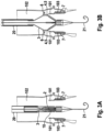
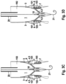
- a fabric-like stent structure is particularly suitable for shortening, as in FIG. 3A to FIG. 3F shown, the capture device to reach the ring structure of the collection storage facility.
- the replacement heart valve attached to the at least one stent can be a pericardial valve, a biological heart valve, an artificial heart valve, preferably consisting of biocompatible materials, or a comparable implant or transplant that is suitable for replacing an insufficient heart valve.
- the system therefore offers the advantage of being able to have the optimal design of a replacement heart valve depending on the patient-specific conditions.
- the replacement heart valve has at least two leaflets. With regard to replacing a three-part heart valve, use with more than two, in particular with three leaflets, is also conceivable. The use of the system according to the invention is therefore not limited to replacing an insufficient, native aortic valve, in particular not by the number of leaflets.
- the leaflets of the replacement heart valve have two positions in particular, which they assume during systole and diastole of the heart.
- an equivalent transfer of the functionality of the leaflets in accordance with the biological model is also conceivable for the replacement of the other native heart valves.
- a first position of the leaflets during diastole of the heart, the flow connection between the left ventricle and the aorta is completely closed off, so that backflow of blood is prevented.
- the commissures of the leaflets, the edges on the inside of the vessel are in contact with one another.
- the leaflets assume a second, open position so that blood can be pumped from the ventricle into the aorta.
- the commissures of the leaflets are not in contact with one another in this second position.
- An embodiment of the at least one stent preferably has a coating on the inside and/or outside, which consists of an antimicrobial substance or an antimicrobial carrier material.
- the at least one stent can thus release one or more antimicrobial agents and achieve improved integrability of the implanted system in contact with the surrounding vessel wall.
- an antimicrobial carrier material a combination with other components such as anticoagulants, other antimicrobial agents such as bactericides, etc. is possible, which are placed on and/or on the carrier material.
- the application of a film/membrane to the stent surface and other physical and/or chemical deposition processes for applying a surface coating for the system according to the invention can be used. It is thus possible to apply a coating to the stent surface. to achieve complex release kinetics of different active ingredients.
- a coating of the stent surface can be activated in a controlled manner.
- a preferably antimicrobial effect only occurs when the surface coating has been activated.
- such a controlled activation of the surface coating can be carried out by applying ultrasound from outside the patient's body, whereby at least one toxic substance bound to special carrier media, such as carbon dioxide, is released on the stent surface.
- the application can also be in the form of microthreads or nonwovens from which the active ingredient can be released, whereby these can in particular be bioresorbable polymer materials such as polylactides, polyglycolides, polylactones, polydioxanones, polyglycols, combinations and/or chemical modifications thereof, into which the active ingredient(s) have been incorporated.
- bioresorbable polymer materials such as polylactides, polyglycolides, polylactones, polydioxanones, polyglycols, combinations and/or chemical modifications thereof, into which the active ingredient(s) have been incorporated.
- the system according to the invention has a first apron area inside and a second apron area outside the intended stent, wherein at least one substance applied or introduced or filled is released in the ventricle-side retention area of the stent.
- the ventricle-side retention area is understood to mean the retention area of a stent or stent system according to the invention, which faces the left ventricle of the heart and is opposite the aorta-side retention area.
- the invention further relates to a suitable catheter for introducing an implant into the body of a patient, in particular an implant of the previously type, which is used to treat or replace a heart valve suffering from inflammation, thrombosis or degeneration.
- the catheter has a catheter tip which can be manipulated via a handle on the catheter in such a way that the implant can be released sequentially, i.e. step by step, from the catheter tip.
- this relates to a corresponding system for treating or replacing a heart valve suffering from inflammation and/or infection, wherein this system comprises an implant according to the present invention and a catheter of the aforementioned type.
- the implant is preferably designed to be accommodated in the catheter tip of the insertion catheter in a state in which it is stretched in the longitudinal direction of the implant and compressed or reduced with respect to the radial direction of the implant.
- the catheter tip of the insertion catheter is preferably designed to accommodate the implant in its state in which it is stretched in the longitudinal direction of the implant and reduced with respect to the radial direction of the implant.
- the implant can be accommodated in the catheter tip in an extended state
- the effective outer diameter of the catheter tip and in particular also of a catheter system which connects the catheter tip to the handle of the catheter can have a particularly small diameter.
- the diameter of the catheter is 18F or less.
- hyperplastic tissue changes in particular in the form of heart valve vegetation, are initially compartmentalized in the diseased (native) heart valve, in particular by the hyperplastic tissue changes being received and/or encompassed at least in regions by a suitable capture device which is to be implanted in the patient's body.
- a replacement heart valve can then be implanted to replace the function of the diseased, native heart valve.
- the method can comprise the further step of releasing antimicrobial agents, with the release preferably taking place in situ.
- the implant according to the invention is particularly designed to expand step by step in the implantation site on the diseased native heart valve, one after the other, in a first step the capture device expands and in a second step the replacement heart valve expands.
- the implant is designed to expand step by step at the implantation site on the diseased native heart valve, with the replacement heart valve expanding in a first step and the capture device expanding in a second step.
- the implant has a structure that can be implanted in particular separately from the capture device and heart valve, which structure in particular has a substantially ring-shaped self-expanding structure and can be inserted into the pockets of the native heart valve and serves as an abutment in particular for the capture device or the clamping area of the implant.
- the invention further relates to a catheter for introducing an implant into the body of a patient, in particular an implant for treating or replacing an inflamed, thrombosed or degenerated heart valve of the aforementioned type, wherein the catheter has a catheter tip which can be manipulated via a handle of the catheter such that the implant can be gradually released from the catheter tip.
- the invention relates to a system for treating or replacing an inflamed, thrombosed or degenerated heart valve with an implant of the type according to the invention and a catheter of the aforementioned type, wherein the implant is designed to be accommodated in the catheter tip in particular in a state stretched in the longitudinal direction of the implant and reduced with respect to the radial direction of the implant, and wherein the catheter tip is designed to accommodate the implant in particular in its state stretched in the longitudinal direction of the implant and reduced with respect to the radial direction of the implant.
- the system comprises an additional and/or independent, in particular at least substantially annular, self-expanding implant, which is also referred to herein as an "abutment implant” and is designed to serve in particular as an abutment for the implant, and which is foldable in particular via an extension in a radial direction and can be accommodated in folded form in a catheter tip and implanted at the implantation site in such a way that in the implanted state of the implant, at least one valve leaflet of the heart valve to be treated can be accommodated at least in some areas between the implant and the additional and/or independent implant.
- an additional and/or independent, in particular at least substantially annular, self-expanding implant which is also referred to herein as an "abutment implant” and is designed to serve in particular as an abutment for the implant, and which is foldable in particular via an extension in a radial direction and can be accommodated in folded form in a catheter tip and implanted at the implantation site in such a way that in the implante
- the abutment implant can be designed to be received in the catheter tip in the compressed state in such a way that the abutment implant is not aligned coaxially but orthogonally to the catheter tip axis in the compressed state and can also be released step by step at the implantation site by means of one or more pressure-stable connections.
- the invention relates to a method for treating or replacing an inflamed, thrombosed or degenerated heart valve, wherein the method comprises the step of compartmentalizing tissue changes or tissue deposits, in particular in the form of heart valve vegetations or deposits, in particular by the tissue changes or tissue deposits being received and/or encompassed at least in regions by a capture device.
- the method preferably further comprises the method step of implanting a replacement heart valve to replace the diseased native heart valve, wherein the step of compartmentalization and the step of implanting the replacement heart valve and the abutment are preferably carried out one after the other in time.
- the method further comprises the step of releasing antimicrobial, antithrombotic and cell growth inhibitory active substances, wherein the release takes place in situ.
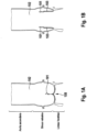
- FIG.1 is shown schematically and in a sectional view the anatomy of an aortic valve 100 suffering from endocarditis, in which FIG 1A the aortic valve closed and in FIG 1B the aortic valve is shown closed.
- the aortic valve 100 is one of the four heart valves. It is located in the aorta 102, directly at its origin from the left ventricle and prevents the backflow of blood at the beginning of the relaxation phase (diastole) of the heart.
- the aortic valve 100 is a pocket valve that usually consists of three crescent-shaped pockets.
- the valve and its bulges (sinus) are located in the initial part of the ascending aorta 102 (aorta ascendens).
- the pockets are named according to the branches of the two coronary arteries from the corresponding sinuses: right coronary pocket at the branch of the right coronary artery, left coronary pocket at the branch of the left coronary artery and acoronary pocket (sinus without a branching coronary artery).
- aortic valve insufficiency and/or aortic valve endocarditis it is often necessary to replace the native aortic valve 100 with a replacement heart valve 10.
- Aortic valve endocarditis can be caused by numerous microorganisms. Gram-positive bacterial species such as streptococci, enterococci and staphylococci are particularly common as human pathogens in infectious endocarditis. If these colonize the endocardium of the native aortic valve 100, for example, as a result of bacteremia, infectious endocarditis occurs, which is an inflammation of the inner lining of the heart (endocardium). If left untreated, the disease is usually fatal.
- tissue deposits 101 of the heart valves 100 are also formed by bacteria, their metabolic products and other components of the human organism. Such tissue deposits 101 are also referred to as "heart valve vegetation". So-called non-bacterial thrombotic vegetations can be considered a prerequisite for bacterial colonization. These are platelets that attach themselves to damaged endothelium of the heart valves 100.
- the heart valve vegetation 101 is formed in particular in the form of thread-like or membrane-like structures on the native heart valves 100, which can be up to more than 25 mm long.
- a further complication is the risk of germs being spread to other organs, where abscesses can then form.
- Blood poisoning and septic or toxic shock caused by poisonous bacteria can lead to acute organ failure (e.g. kidney, liver and/or lung failure).
- the invention provides that the heart valve vegetation 101 is appropriately compartmentalized during the replacement of a heart valve 100 suffering from endocarditis. This can preferably be done before the native heart valve 100 is replaced by a heart valve prosthesis 10, or during the replacement or after the replacement of the diseased native heart valve 100.
- An implant 1 is used to compartmentalize the heart valve vegetation 101, which has a capture device 2, wherein this capture device 2 can be introduced into the patient's body in a compressed state in a minimally invasive manner and can be expanded at the implantation site on the diseased heart valve 100.
- the capture device 2 is designed to encompass and/or receive tissue deposits 101 (heart valve vegetation) at least in some areas, at least in the implanted and expanded state, and thus to compartmentalize them.
- the implant 1 with the capture device 2 further comprises a corresponding replacement heart valve 10, which is either a self-expandable or balloon-expandable replacement valve, which can be introduced into the patient's body in a compressed state, in particular in a minimally invasive manner. and is expandable at the implantation site on the diseased heart valve 100 such that the replacement heart valve 10 at least substantially takes over the function of a native heart valve 100.
- a corresponding replacement heart valve 10 which is either a self-expandable or balloon-expandable replacement valve, which can be introduced into the patient's body in a compressed state, in particular in a minimally invasive manner. and is expandable at the implantation site on the diseased heart valve 100 such that the replacement heart valve 10 at least substantially takes over the function of a native heart valve 100.
- the replacement heart valve 10 is preferably assigned a stent 3 to support and carry the replacement heart valve 10.
- the stent 3 assigned to the replacement valve 10 is designed to radially displace the diseased native heart valve 100 or the heart valve leaflets 103 of the diseased, native heart valve 100 in order to stretch the replacement heart valve 10 in its place and to enable faultless valve function during systole and diastole of the heart.
- the stent 3 associated with the replacement valve 10 is particularly structurally designed so that it can provide a secure hold during the periodic heartbeat of the replacement heart valve 10, so that the implant 1 cannot be detached from the native biological tissue, in particular from the vessel wall, and washed out of the implantation site due to changing pressure conditions in the heart.
- the at least one stent 3 associated with the replacement valve 10 preferably also serves as an anchoring structure for the capture device 2 of the implant 1.
- the at least one stent 3 associated with the replacement valve 10 preferably also serves as an anchoring structure for the capture device 2 of the implant 1.
- several stents 3 or stent systems for these functions carrier and support structure of the replacement heart valve 10 and anchoring structure of the capture device 2, which are suitably connected to one another or can be connected.
- the stent(s) 3 of the implant 1 according to the invention can be expanded by balloon expansion using a balloon catheter and positioned at the implantation site.
- the compressed stent 3 hidden in the catheter is expanded by a catheter balloon that is filled with liquid or gas.
- the at least one stent 3 of the implant 1 according to the invention can be a self-expanding stent 3.
- the stent 3 consists of a shape memory alloy, preferably nitinol.
- nitinol In addition to the shape memory effect at a specific transition temperature close to body temperature, nitinol also has superelasticity, biocompatibility and corrosion resistance. Nitinol is therefore already widely used in medical technology.
- superelasticity is advantageous with regard to the compressed delivery form of a stent in the transcatheter procedure and the expansion at the implantation site.
- the radial prestressing force of the at least one stent 3 of the implant 1 can be further increased after self-expansion by balloon expansion, whereby in turn a higher stability of the implant 1 according to the invention can be achieved in the implanted state.
- the replacement heart valve 10 attached to the at least one stent 3 can be a pericardial valve, a biological (for example, porcine or bovine) heart valve, an artificial heart valve 100, preferably made of biocompatible materials, or a comparable implant or transplant which is suitable for replacing a heart valve 100 suffering from endocarditis.
- the implant 1 according to the invention thus offers the advantage of being able to have the optimal design of a replacement heart valve 10 depending on the patient's specific conditions.
- the replacement heart valve 10 has at least two leaflets 103.
- the use with more than two, in particular with three leaflets 103 is also conceivable.
- the use of the implant 1 according to the invention is not only limited to the treatment and replacement of a native aortic valve 100 suffering from endocarditis, in particular not by the number of leaflets 103.
- the leaflets 103 of the replacement heart valve 10 have two positions in particular, which they assume during the systole and the diastole of the heart.
- an equivalent transfer of the functionality of the leaflets 103 in accordance with the biological model is also conceivable for the replacement of the other native heart valves 100.
- a first position of the leaflets 103 during the diastole of the heart, the flow connection between the left ventricle and the aorta 102 is completely closed, so that blood backflow is prevented.
- the commissures of the leaflets 103 ie the edges located on the inside of the vessel, are in contact with one another.
- the leaflets 103 assume a second, open position so that blood can be pumped from the ventricle into the aorta 102.
- the commissures of the leaflets 103 have no contact with each other in this second position.
- the capture device 2 of the implant 1 according to the invention can have an anchoring structure in the form of a stent 3, whereby this stent 3 can also serve as a carrier and support structure of the replacement heart valve 10. In this way, the capture device 2 can be suitably fixed and positioned in the implantation site.
- a capture structure 4 is connected to the anchoring structure 3, which extends downstream from the anchoring structure 3 in the direction of blood flow into a vessel 102 that is fluidly connected to the diseased heart valve 100, in particular into the aorta, and in the expanded state has at least one clamping region 5, which is designed to interact with at least one heart valve leaflet 103 of the diseased heart valve 100 in the expanded and implanted state of the capture device 2 in such a way that the at least one heart valve leaflet 103 is positioned between the anchoring structure 3 and the capture structure 4.
- the clamping region 5 of the catching device 2 can have at least one clamping arm or clamping bracket, which is designed to expand at least partially in the radial direction during the expansion of the catching device 2 in the implantation site.
- the clamping region 5 can have at least one region 6 pointing at least substantially in the direction of the anchoring structure 3 at a distal end region facing away from the anchoring structure 3 in order to optimize an encircling or reception of the heart valve vegetation 101 and to interact in a force-fitting or form-fitting manner with a structure 7 according to the invention (e.g. abutment implant).
- a structure 7 according to the invention e.g. abutment implant
- a structure 7 can be inserted before the implant 1 with the capture device 2 and the replacement heart valve 10 is introduced, which structure has a substantially ring-shaped structure and can be supported, for example, in the pockets of the native heart valve 100 and can fill them.
- This structure 7 serves as an abutment for the implant 1 to be implanted subsequently.
- the ring-shaped abutment structure 7 has a shape and height in the longitudinal direction which, in the implanted state, does not block the openings of the coronary arteries.
- the implant 1 according to the invention can - as shown in the drawings - be implanted step by step as a coherent system within the framework of an introduction procedure.
- the implant is implanted step by step, wherein in a first step the capture device is expanded and pushed downwards and connected to the abutment implant 7 in a force-fitting or form-fitting manner and in a second step the heart valve is expanded and released.
- the implant 1 is expanded step by step over time, wherein in a first step the replacement heart valve 10 is implanted and expanded, and in a subsequent second step the capture device 2 is expanded.
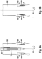
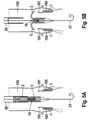
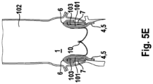
- FIG. 5A to FIG. 5E The insertion procedure shown provides that first the capture device 2 is expanded and then the replacement heart valve 10.
- the implant 1 which is held in a compressed state in a catheter tip of an insertion catheter system 20, is introduced to the implantation site via a transfemoral access.
- the implant 1 it is also conceivable for the implant 1 to be introduced via a transapical route, ie coming from the apex of the heart.
- the ring-shaped abutment 7 is preferably first introduced into the pockets of the native heart valve 100.
- the invention is not limited to the provision of such an abutment 7.
- abutment implant 7 provides for this to be introduced coaxially in the catheter, i.e. with radial compression and thus axial stretching via a catheter and then to expand radially (itself).
- Another embodiment of the abutment implant 7 provides for this to be introduced not coaxially, but at least essentially folded and orthogonal to the catheter axis in order to introduce a larger volume with the same catheter diameter.
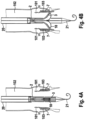
- the implant 1 according to the invention is then implanted via a catheter 20, in the catheter tip of which the implant 1 is received in a compressed state.
- the implant 1 is received in the catheter tip of the insertion catheter system 20 in a state that is stretched in the longitudinal direction of the implant 1 and reduced with respect to the radial direction of the implant 1, in order to be able to minimize the diameter of the catheter system 20.
- a guide wire 21 is preferably used for implantation in order to simplify and make the insertion of the catheter safer.
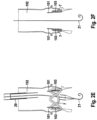
- the catheter tip is moved in the direction of the ventricle until the replacement heart valve 10 accommodated in the catheter tip is at the level of the native heart valve 100.
- the stent 3 assigned to the replacement heart valve 10 expands, it presses the native heart valve leaflets 103 of the diseased heart valve 100 in the radial direction, with the ring-shaped structure 7 optionally previously inserted into the pockets of the native heart valve 100 serving as an abutment.
- FIG.4B In the state shown, it is particularly possible to check the correct positioning of the replacement heart valve 10 and its perfect functionality. If it turns out that the replacement heart valve 10 is not positioned in the right place, this can be easily corrected. If, however, the replacement heart valve 10 does not function properly, it can be returned to the catheter sleeve and the implant 1 can be removed from the patient's body.
- the capture device 2 can then be released by displacing a corresponding second sleeve-shaped region of the catheter tip distally.
- the capture device 2 is preferably "programmed" in such a way that when it expands it encloses the heart valve vegetation 101 and thus removes it from the main blood flow.
- the capture device 2 is first released from the catheter tip.
- the replacement heart valve 10 or the stent 3 associated with the replacement heart valve 10 is then released.
- This insertion procedure has the advantage that the heart valve vegetation 101 is already compartmentalized before the replacement heart valve 10 expands; however, the FIG. 5A to 5E The insertion procedure shown requires that the catheter tip be inserted further towards the ventricle.
- FIG. 3A to FIG 3F and in FIG. 5A to 5E In the insertion procedures shown, when the capture device 2 is released, a clamping area 5 initially expands, wherein this clamping area 5 is connected to an anchoring structure 3 of the implant 1 (not yet implanted).
- clamping region 5 has at least one region 6 pointing essentially in the direction of the anchoring structure 3 at a distal end region facing away from the anchoring structure 3, which region significantly simplifies the capture and enclosing of the heart valve vegetation 101.
- the replacement heart valve 10 or a stent 3 associated with the replacement heart valve 10 is released by manipulating a front sleeve-shaped region of the catheter tip in the proximal direction.
- the implant 1 and/or the ring-shaped abutment 7 inserted into the pockets of the native heart valve 100 are/is particularly designed to release one or more active substances, in particular antibacterial, antithrombotic and cell growth-inhibiting compounds, in situ.
- Implant 1 for treating and/or replacing a heart valve 100 suffering from inflammation and/or infection wherein the implant 1 has a capture device 2 which, in a compressed state, can be introduced into the patient's body in a minimally invasive manner and can be expanded at the implantation site on the diseased heart valve 100, wherein the capture device 2 is designed to compartmentalize tissue changes or tissue deposits 101, in particular in the form of heart valve vegetations or deposits, at least in the implanted and expanded state, in particular by the tissue change or deposit 101 being encompassed and/or received by the capture device 2 at least in part.
- tissue changes or tissue deposits 101 in particular in the form of heart valve vegetations or deposits
- Implant 1 according to aspect 1, wherein the capture device 2 has an anchoring structure 3 for fixing and/or positioning the capture device 2 at the implantation site, and wherein the capture device 2 has a capture structure 4 connected to the heart valve 3, which extends downstream from the anchoring structure 3 in a extends into a vessel 102 that is fluidically connected to the diseased heart valve 100 and, in the expanded state, has at least one clamping region 5 that is designed to interact with at least one heart valve leaflet 103 of the diseased heart valve 100 in the expanded and implanted state of the capture device 2 in such a way that at least one heart valve leaflet 103 is pressed in the direction of a vessel wall and/or at least partially enclosed by the capture device 2.
- Implant 1 wherein the at least one clamping region 5 has at least one clamping arm or clamping bracket, which is designed to expand at least partially in the radial direction during the expansion of the capture device 2 in the implantation site, wherein the clamping region 5 is preferably designed to interact with a further abutment structure 7 to be implanted at a distal end region facing away from the anchoring structure 3.
- Implant 1 according to one of aspects 1 to 3, wherein the implant 1 further comprises an expandable replacement heart valve 10, which in a compressed state can be introduced into the patient's body in particular in a minimally invasive manner and can be expanded at the implantation site on the diseased heart valve 100 such that the replacement heart valve 10 takes over the function of a native heart valve 100, wherein the replacement heart valve 10 and the capture device 2 are preferably connected or connectable to one another, preferably via a common anchoring structure 3, which is designed to be positioned and fixed in particular in the region of the roots of the heart valve leaflets 103 of the native heart valve 100.
- a common anchoring structure 3 which is designed to be positioned and fixed in particular in the region of the roots of the heart valve leaflets 103 of the native heart valve 100.
- Implant 1 according to aspect 4, wherein the implant 1 is designed to expand step by step in the implantation site on the diseased native heart valve 100, wherein in a first step the capture device 2 and in a second step the replacement heart valve 10 expand; or wherein the implant 1 is designed to be implanted step by step in the implantation site on the diseased native heart valve 100. expand, whereby in a first step the replacement heart valve 10 expands and in a second step the capture device 2 expands.
- Implant 1 according to one of aspects 1 to 5, wherein the implant 1 further comprises a structure 7 which can be implanted in particular separately from the capture device 2 and heart valve 3, which structure in particular has a substantially ring-shaped self-expanding structure and can be inserted into the pockets of the native heart valve 100 and serves as an abutment in particular for the capture device 2 or the clamping region 5 of the implant 1.
- a structure 7 which can be implanted in particular separately from the capture device 2 and heart valve 3, which structure in particular has a substantially ring-shaped self-expanding structure and can be inserted into the pockets of the native heart valve 100 and serves as an abutment in particular for the capture device 2 or the clamping region 5 of the implant 1.
- Implant 1 according to one of aspects 1 to 6, wherein the implant 1 and/or an abutment structure 7 associated with the implant 1 are designed to release antimicrobial, antithrombotic or cell growth-inhibiting active substances, at least in the implanted state.
- Implant 1 according to aspect 7, wherein the capture device 2 and/or a replacement heart valve 10 possibly belonging to the implant 1 and/or an abutment structure 7 associated with the implant 1 has a coating with active substances for releasing the active substances.
- Implant 1 according to aspect 7 or 8, wherein, for the release of the active substances, the implant 1 or components of the implant 1 and/or an abutment structure 7 associated with the implant 1 has at least one bioresorbable structure, which in particular represents a thread, fleece and/or membrane structure; and/or wherein the implant 1 or components of the implant 1 and/or an abutment structure 7 associated with the implant 1 have/have at least one active substance-releasing region which is at least partially coated or covered with at least one polymer material and is designed to control the direction of an active substance release and/or to at least greatly reduce an active substance release in the direction of the at least one polymer material used for the coating.
- the implant 1 or components of the implant 1 and/or an abutment structure 7 associated with the implant 1 has at least one bioresorbable structure, which in particular represents a thread, fleece and/or membrane structure; and/or wherein the implant 1 or components of the implant 1 and/or an abutment structure 7 associated with the implant 1 have/have at least one active substance-releasing region
- Catheter 20 for introducing an implant 1 into the body of a patient, in particular an implant 1 for treating or replacing an inflamed, thrombosed or degenerated heart valve 100 according to one of aspects 1 to 9, wherein the catheter 20 has a catheter tip which can be manipulated via a handle of the catheter 20 such that the implant 1 can be gradually released from the catheter tip.
- the system has an additional and/or independent, in particular at least substantially ring-shaped, self-expanding implant 7, which is designed to serve in particular as an abutment for the implant 1, and which is foldable in particular via an extension in a radial direction and can be accommodated in folded form in a catheter tip and implanted at the implantation site in such a way that in the implanted state of the implant, at least one valve leaflet 103 of the heart valve 100 to be treated can be accommodated at least in some regions between the implant 1 and the additional and/or independent implant 7.
- the additional and/or independent implant 7 is designed to be accommodated in the catheter tip in the compressed state such that the additional and/or independent implant 7 is not aligned coaxially but orthogonally to the catheter tip axis in the compressed state and can also be released step by step at the implantation site by means of one or more pressure-stable connections.
- Method for treating or replacing a heart valve 100 that is inflamed, thrombosed or degenerated comprising the step of compartmentalizing tissue changes or tissue deposits 101, in particular in the form of heart valve vegetations or deposits, in particular by Tissue changes or tissue deposits 101 are at least partially absorbed and/or encompassed by a capture device 2.
- Method according to aspect 14 wherein the method further comprises the method step of implanting a replacement heart valve 10 to replace the diseased native heart valve 100, wherein the step of compartmentalization and the step of implanting the replacement heart valve 10 and the abutment 7 are preferably carried out one after the other in time; and/or wherein the method further comprises the method step of releasing antimicrobial, antithrombotic and cell growth-inhibiting active substances, wherein the release takes place in situ.
Landscapes
- Health & Medical Sciences (AREA)
- Cardiology (AREA)
- Engineering & Computer Science (AREA)
- Biomedical Technology (AREA)
- Heart & Thoracic Surgery (AREA)
- Transplantation (AREA)
- Oral & Maxillofacial Surgery (AREA)
- Vascular Medicine (AREA)
- Life Sciences & Earth Sciences (AREA)
- Animal Behavior & Ethology (AREA)
- General Health & Medical Sciences (AREA)
- Public Health (AREA)
- Veterinary Medicine (AREA)
- Prostheses (AREA)
Abstract
Description
- Die vorliegende Erfindung ist aus dem Gebiet der Herzchirurgie und Kardiologie und betrifft insbesondere die Behandlung und/oder den Ersatz einer an einer Entzündung und/oder Infektion erkrankten Herzklappe.
- Es gibt vier Klappen in den nativen Herzen, die zum Ausrichten des Blutflusses durch die beiden Seiten des Herzens in einer Richtung nach vorne dienen. An der linken (systemischen) Seite des Herzes sind die Mitralklappe, die zwischen dem linken Vorhof und der linken Kammer liegt, und die Aortenklappe, die zwischen der linken Kammer und der Aorta liegt. Diese beiden Klappen leiten sauerstoffreiches Blut, welches von der Lunge kommt, durch die linke Seite des Herzens hindurch in die Aorta hinein zum Verteilen auf den Körper. An der rechten (pulmonalen) Seite des Herzens sind die Trikuspidalklappe, die zwischen dem rechten Vorhof und der rechten Kammer liegt, und die Pulmonalklappe, die zwischen der rechten Kammer und der Pulmonalarterie liegt. Diese beiden Klappen leiten sauerstoffarmes Blut, welches von dem Körper kommt, durch die rechte Seite des Herzens hindurch in die Pulmonalarterie hinein zum Verteilen auf die Lunge, wo es wieder sauerstoffangereichert wird, um den Kreislauf von neuem zu beginnen.
- Alle vier dieser Herzklappen sind passive Strukturen dadurch, dass sie selbst keinerlei Energie aufwenden und keinerlei aktive kontraktile Funktion durchführen. Sie bestehen aus beweglichen "Segeln", die gelegentlich auch als "Leaflets" bezeichnet werden, und die dafür bestimmt sind, in Erwiderung auf unterschiedliche Drücke an jeder Seite der Klappe einfach zu öffnen und zu schließen. Die Mitral- und Trikuspidalklappe werden wegen ihrer Lage zwischen einem Vorhof und einer Kammer an jeder Seite des Herzens als "Vorhof-Kammerklappen" bezeichnet. Die Mitralklappe hat zwei Segel und die Trikuspidalklappe hat drei Segel. Die Aorten- und Pulmonalklappe werden als "halbmondförmige Klappen" bezeichnet, welche passenderweise "Segel" genannt werden. Die Aorten- und Pulmonalklappen haben jeweils drei Segel.
- Die Endokarditis ist eine Entzündung der Herzinnenhaut (Endokard), welche die Herzhöhlen und den herznahen Anteil der Arterien und Venen auskleidet und auch die Struktur der Herzklappensegel bildet. Zahlreiche Mikroorganismen können eine Endokarditis verursachen - besonders grampositive Bakterienspezies wie Streptokokken, Enterokokken und Staphylokokken. Wenn diese im Zuge einer Bakteriämie das Endokard besiedeln, entsteht eine infektiöse Endokarditis.
- Abhängig von der Art des Auslösers tritt eine mortale Folge der Endokarditis in ca. 25% der Fälle ein.
- Eine Möglichkeit zur Behandlung einer Endokarditis ist nach dem Stand der Technik die chirurgische Entfernung der entzündeten Herzklappe und die Implantation einer künstlichen Herzklappe bzw. Ersatzherzklappe. In der Regel werden hierfür arbeits- und kostenintensive Operationen durchgeführt, die mit einer hohen Patientenbelastung und einem beträchtlichen Risiko verbunden sind. Im Detail wird der Brustkorb des Patienten eröffnet, das Herz mittels kardiopleger Lösung zum Stillstand gebracht, die körpereigene Herzklappe entfernt und an dessen Stelle eine künstliche Herzklappe an das körpereigene Gewebe angenäht. Neuere Methoden, wie in
WO2006/076890 A1 dargestellt, sehen eine Transkatheter-Implantation künstlicher Herzklappen unter Einsatz eines Stents als Stützstruktur vor, die aber nur bei degenerierten Aortenklappenerkrankungen einsetzbar sind. - Bei entzündeten Herzklappen mit bakteriellen An- bzw. Ablagerungen im Sinne von größeren Vegetationen sind bisher nur operative Verfahren anwendbar, die das infizierte, entzündete Material im umliegenden Gewebe der Herzklappe und die Herzklappe selbst entfernen und eine künstliche Herzklappe einnähen. Die kathetergeführten Klappenimplantationen sind bei entzündeten Herzklappen kontraindiziert, da, wie oben genannt, dass entzündete Material hierbei nicht entfernt werden kann. Gerade bei der Endokarditis sind aber die operativen Verfahren, die bei 75% der Fälle mit Endokarditis angewandt werden (25% werden nicht operiert, weil die Patienten entweder nicht mehr operabel sind oder weil es sich nur um eine leichte Entzündung handelt) aber besonders risikoreich. Dies liegt daran, dass die Patienten mit einer Endokarditis meist erhebliche Begleiterkrankungen aufweisen, die im Zusammenhang mit der Herzklappenentzündung stehen, wie Embolisationen in das Gehirn, Nieren, Haut und weitere Organe und weil die Patienten septisch, d.h. mit hohem Fieber und entzündungsbedingten Beeinträchtigungen und einer destruierten Klappe, die zu einer Herzinsuffizienz geführt hat, notfallmäßig operiert werden.
- Auf der Grundlage dieser Problemstellung liegt der Erfindung somit die Aufgabe zu Grunde, durch die Implantation einer kathetergeführten Herzklappe, die lokal gleichzeitig die Infektion und/oder Thrombose und die degenerierte Herzklappe behandeln kann.
- Im Hinblick auf das Implantat wird die der Erfindung zu Grunde liegende Aufgabe insbesondere durch den Gegenstand des unabhängigen Patentanspruches 1 gelöst, wobei vorteilhafte Weiterbildungen des erfindungsgemäßen Implantates in den entsprechenden Unteransprüchen angegeben sind.
- Im Hinblick auf das Verfahren wird die der Erfindung zu Grunde liegende Aufgabe insbesondere durch den Gegenstand des nebengeordneten Patentanspruches 14 gelöst.
- Demgemäß betrifft die Erfindung insbesondere ein Implantat zur Behandlung oder zum Ersatz einer an einer Entzündung und/oder Infektion erkrankten Herzklappe, wobei das Implantat eine Fangeinrichtung aufweist, welche in einem komprimierten Zustand minimal-invasiv in den Körper des Patienten einführbar und im Implantationsort an der erkrankten Herzklappe expandierbar ist. Die Fangeinrichtung ist insbesondere ausgebildet, zumindest im implantierten und expandierten Zustand Gewebeauflagerung insbesondere in Gestalt einer Herzklappenvegetation zu kompartimentieren, und zwar insbesondere indem die Gewebeauflagerung zumindest bereichsweise von der Fangeinrichtung umgriffen und/oder aufgenommen wird.
- Für die Fangeinrichtung des erfindungsgemäßen Implantates kommen verschiedene Ausführungsformen in Frage. So ist es beispielsweise denkbar, dass die Fangeinrichtung eine netz- oder gitter- oder membranartige Struktur aufweist, über welche die Gewebeauflagerung an der erkrankten nativen Herzklappe zumindest bereichsweise umgriffen und/oder aufgenommen werden kann, um diese so entsprechend zu kompartimentieren.
- Alternativ oder zusätzlich hierzu ist es aber auch denkbar, dass die Fangeinrichtung zumindest bereichsweise eine Gewebestruktur insbesondere aus einem bioresorbierbaren Material aufweist, um so im implantierten und expandierten Zustand des Implantates bzw. der Fangeinrichtung eine Einkapselung der Gewebeauflagerung im Bereich der zu behandelnden nativen Herzklappe ermöglichen zu können. Die Gewebestruktur der Fangeinrichtung kann beispielsweise aus bioresorbierbaren Fäden, insbesondere Mikro-Fasern, aufgebaut sein, die beispielsweise derart untereinander vernetzt sind, dass ein Vlies oder vliesartige Struktur gebildet wird.
- Selbstverständlich kommen aber auch andere Ausführungsformen sowie deren Kombination für die Fangeinrichtung in Frage.
- Um eine möglichst genaue und sichere Fixierung und/oder Positionierung der Fangeinrichtung im Implantationsort ermöglichen zu können, ist der Fangeinrichtung in bevorzugter Weise eine geeignete Verankerungsstruktur zugeordnet. Dabei kann vorgesehen sein, dass eine Fangstruktur geeignet mit der Verankerungsstruktur verbunden ist, um so insgesamt die Fangeinrichtung auszubilden. In Blutstromrichtung gesehen sollte gemäß Ausführungsformen der Fangeinrichtung die mit der Verankerungsstruktur verbundene Fangstruktur sicher stromabwärts in ein strömungsmäßig mit der erkrankten Herzklappe verbundenes Gefäß erstrecken, wenn das Implantat im implantierten Zustand vorliegt.
- Darüber hinaus kann die Fangstruktur im expandierten Zustand mindestens einen Aufspannbereich aufweisen, welcher ausgebildet ist, im expandierten und implantierten Zustand der Fangeinrichtung mit mindestens einem Herzklappensegel der erkrankten Herzklappe derart wechselzuwirken, dass das mindestens eine Herzklappensegel in Richtung einer Gefäßwand gedrückt wird. Vorzugsweise ist der Aufspannbereich der Fangeinrichtung ausgebildet, dass möglichst alle Herzklappensegel der erkrankten Herzklappe geeignet in Richtung der Gefäßwand gedrückt werden. Auf diese Weise können nicht nur die Gewebeauflagerung (insbesondere Herzklappenvegetation) an den Segeln der erkrankten Herzklappe kompartimentiert werden, sondern es wird gleichzeitig auch schon die erkrankte Herzklappe für den Ersatz durch eine Ersatzherzklappe (Herzklappenprothese) vorbereitet.
- Als Aufspannbereich, über den der bzw. die Herzklappensegel der erkrankten nativen Herzklappe in Richtung der Gefäßwand gedrückt werden, kann auf unterschiedliche Weise ausgebildet sein. Insbesondere bietet es sich an, dass der mindestens eine Aufspannbereich zu mindestens einen Aufspannarm oder Aufspannbügel aufweist, welcher ausgebildet ist, bei der Expansion der Fangeinrichtung im Implantationsort zumindest bereichsweise in radialer Richtung zu expandieren.
- Um eine möglichst wirksame Kompartimentierung der Gewebeauflagerung erzielen zu können, ist gemäß Ausführungen der Erfindung vorgesehen, dass der Aufspannbereich an einem der Verankerungsstruktur abgewandten, distalen Endbereich mindestens einen zumindest im Wesentlichen in Richtung der Verankerungsstruktur zeigenden Bereich aufweist.
- Gemäß Ausführungsformen des erfindungsgemäßen Implantats weist dieses ferner eine insbesondere separat von der Fangeinrichtung implantierbare Struktur auf, welche insbesondere einen im Wesentlichen ringförmigen Aufbau aufweist und in die Taschen (zwischen den Segeln und der Gefäßwand) der nativen Herzklappe einsetzbar ist und als Widerlager insbesondere für die Fangeinrichtung und/oder den Aufspannbereich des Implantats dient.
- Beispielsweise kann diese insbesondere separat von der Fangeinrichtung implantierbare Struktur als ein insbesondere zumindest im Wesentlichen ringförmiges Widerlager-Implantat ausgeführt sein, welches derart im Implantationsort implantierbar ist, dass im implantierten Zustand des Implantates zwischen dem Implantat und dem Widerlager-Implantat zumindest bereichsweise mindestens ein Klappensegel der zu behandelnden Herzklappe aufnehmbar ist.
- Gemäß einem weiteren Aspekt der vorliegenden Erfindung dient das Implantat insbesondere zum Ersatz einer an einer Entzündung und/oder Thrombose und/oder Degeneration erkrankten, und insbesondere einer an einer Endokarditis erkrankten Herzklappe, wobei das Implantat zusätzlich zu der bereits diskutierten Fangeinrichtung eine expandierbare Ersatzherzklappe bzw. Herzklappenprothese aufweist, welche in einem komprimierten Zustand insbesondere minimal-invasiv in den Körper des Patienten einführbar und im Implantationsort an der erkrankten Herzklappe derart expandierbar ist, dass die Ersatzherzklappe bzw. Herzklappenprothese zumindest im Wesentlichen die Funktion einer nativen Herzklappe übernimmt.
- Gemäß Ausführungsformen ist der Ersatzherzklappe mindestens ein geeigneter Stent zugeordnet, um die Ersatzherzklappe insbesondere im implantierten Zustand geeignet abzustützen und zu halten. Der Stent stellt somit die Träger- und Stützstruktur der Ersatzherzklappe dar und dient gleichzeitig der Positionierung und Fixierung der Ersatzherzklappe am Implantationsort.
- Selbstverständlich ist es in diesem Zusammenhang aber auch denkbar, dass der Ersatzherzklappe nicht nur ein einziger Stent, sondern mehrere, insbesondere zwei oder drei Stents zugeordnet sind, um beispielsweise im Implantationsort eine so genannte Stent-in-Stent-Lösung realisieren zu können, wonach ein erster Stent im Bereich zwischen Aortenwand und der nativen Herzklappensegel als Widerlager fixiert ist, und ein zweiter Stent mit der daran befestigten Ersatzherzklappe in den bereits implantierten Stent eingesetzt wird. Eine solche Stent-In-Stent-Lösung bietet den Vorteil, dass die Ersatzherzklappe einen festen Sitz hat und biologisches Material effizienter kompartimentiert werden kann. Ein weiterer Vorteil ist darin zu sehen, dass das Implantat zum Ersatz einer an einer Endokarditis erkrankten Herzklappe komponentenweise implantiert werden kann, so dass ein Einführ-Kathetersystem mit einem maximalen Katheterdurchmesser von insbesondere weniger als 22 Fr verwendet werden kann, da beide Komponenten auch Träger von Wirksubstanzen seien können und somit bei gleichem Katheterdurchmesser insgesamt ein größeres Volumen eingeführt werden kann.
- Gemäß Realisierungen des erfindungsgemäßen Implantates ist vorgesehen, dass diese zusätzlich zu der Fangeinrichtung zur Kompartimentierung der Gewebeauflagerungen eine geeignete Ersatzherzklappe mit einem entsprechend zugeordneten Stent aufweist, wobei dieser Stent die Träger- und Stützstruktur der Ersatzherzklappe darstellt. Darüber hinaus kann der der Ersatzherzklappe zugeordnete Stent ausgebildet sein, im Implantationsort die Herzklappensegel der nativen Herzklappe zu verdrängen, insbesondere in radialer Richtung und vorzugsweise derart, dass die Herzklappensegel der nativen Herzklappe an oder in Richtung der Gefäßwand gedrückt werden.
- In diesem Zusammenhang bietet es sich auch an, dass der der Ersatzherzklappe zugeordnete Stent, gleichzeitig eine oder die Verankerungsstruktur der Fangeinrichtung ausbildet. Mit anderen Worten, dem der Ersatzherzklappe zugeordnete Stent kann eine Doppelfunktion zukommen: zum einen kann der Stent als Träger- und Stützstruktur der Ersatzherzklappe dienen, wobei gleichzeitig die Positionierung und Fixierung der Ersatzherzklappe im Implantationsort an der erkrankten nativen Herzklappe sichergestellt ist. Andererseits kann der, der Ersatzherzklappe zugeordnete Stent, als Verankerungsstruktur für die Fangeinrichtung dienen, wobei dann eine entsprechende Fangstruktur an dem als Verankerungsstruktur der Fangeinrichtung dienenden Stent befestigt oder befestigbar ist.
- Um zu erreichen, dass das Implantat in einer möglichst minimal-invasiven Weise unter Verwendung eines möglichst dünnen Einführ-Kathetersystems in den Körper des Patienten einführbar ist, bietet es sich an, dass das Implantat ausgebildet ist, im Implantationsort an der erkrankten nativen Herzklappe zeitlich gesehen nacheinander schrittweise zu expandieren. Gemäß Ausführungsformen ist dabei vorgesehen, dass in einem ersten Schritt die Fangeinrichtung expandiert, um die Gewebeauflagerungen zu einzufangen und zu kompartimentieren, wobei anschließend eine Expansion der Ersatzherzklappe erfolgt. Selbstverständlich ist die Erfindung jedoch nicht auf diese Reihenfolge beschränkt. Vielmehr kann das Implantat auch ausgebildet sein, dass in einem ersten Schritt die Ersatzherzklappe expandiert und dadurch die Herzklappensegel der nativen Herzklappe mit den Gewebeauflagerungen radial nach außen drückt, wobei anschließend mit Hilfe der Fangeinrichtung die radial nach außen gedrückten Herzklappensegel und insbesondere Gewebeauflagerungen an den Herzklappensegeln der nativen Herzklappe - beispielsweise auch in Verbindung mit einer zuvor separat eingefügten Widerlager-Struktur - geeignet kompartimentiert werden.
- In einer bevorzugten Weiterbildung ist das erfindungsgemäße Implantat ferner ausgebildet, im implantierten Zustand Wirkstoffe freizusetzen. Auf diese Weise kann vor Ort, das heißt in situ und topisch, die Entzündung, Thrombose oder Degeneration der nativen Herzklappe behandelt und die Infektion, Thrombose oder Degeneration kontrolliert werden, ohne das eine zusätzliche Belastung/Gefährdung des Patienten durch eine chirurgische Behandlung der nativen Herzklappe erforderlich ist.
- Als Wirkstoffe kommen insbesondere antimikrobielle, antibiotische, bakterizide, antithrombotische, thrombolytische, zelltoxische und/oder vergleichbare Wirkstoffe in Frage, die mit Hilfe des erfindungsgemäßen Implantates am Ort der Erkrankung an das umliegende Gewebe und in die Blutbahn abgebbar sind.
- Beispielsweise ist es in diesem Zusammenhang denkbar, dass zum Freisetzen der Wirkstoffe die Fangeinrichtung und/oder eine gegebenenfalls zum Implantat gehörende Ersatzherzklappe bzw. ein einer solcher Ersatzherzklappe zugeordneter Stent eine Beschichtung mit den Wirkstoffen aufweist.
- Gemäß Ausführungsformen der vorliegenden Erfindung kommt zum Freisetzen der Wirkstoffe eine bioresorbierbare Struktur zum Einsatz, welche Teil des erfindungsgemäßen Implantates ist, und welche insbesondere eine Faden- und/oder Vliesstruktur und/oder Membranstruktur mit einem Wirkstoff aufweist.
- Das erfindungsgemäße Implantat ist insbesondere ausgelegt, die oben genannten Wirkstoffe am Ort der Erkrankung an das umliegende Gewebe und in die Blutbahn abzugeben.
- Dazu kann das erfindungsgemäße Implantat ein Stent-Wirkstoff-System mit mindestens einem Stent aufweisen, an dem die Fangeinrichtung und/oder eine Ersatzherzklappe befestigt sind/ist. Insbesondere weist das erfindungsgemäße Implantat biokompatible Materialien auf, um eine gute Integrierbarkeit des Systems in das biologische Umfeld nach der Implantation zu gewährleisten. Der mindestens eine Stent stellt die Träger- und Stützstruktur der Ersatzherzklappe dar und dient gleichzeitig der Positionierung und Fixierung des erfindungsgemäßen Systems und insbesondere der Fangeinrichtung am Implantationsort.
- Das Stent-Wirkstoff-System muss die insuffiziente, native Herzklappe radial verdrängen können, um die Herzvegetation mit der Fangeinrichtung zu kompartimentieren und die Ersatzherzklappe anstelle der nativen Herzklappe aufzuspannen und eine fehlerfreie Klappenfunktion während der Systole und Diastole des Herzens sicherzustellen. Auch muss der mindestens eine Stent dazu geeignet sein, während des periodischen Herzschlags der Ersatzherzklappe einen sicheren Halt zu bieten, so dass das erfindungsgemäße System nicht aufgrund wechselnder Druckverhältnissen im Herzen vom biologischen Gewebe, insbesondere von der Gefäßwand, abgelöst und vom Implantationsort ausgeschwemmt werden kann.
- Hierzu kann das erfindungsgemäße System mindestens einen Stent auf, der per Ballonexpansion mit Hilfe eines Ballonkatheters expandiert und am Implantationsort positioniert werden kann. Dabei wird der komprimierte und im Katheter verborgene Stent durch einen mit Flüssigkeit oder Gas zu füllenden Katheterballon expandiert.
- Alternativ kann der mindestens eine Stent des erfindungsgemäßen Systems ein selbstexpandierender Stent sein. Insbesondere besteht der Stent hierzu aus einer Formgedächtnislegierung, vorzugsweise aus Nitinol. Neben dem Formgedächtniseffekt bei einer spezifischen Sprungtemperatur, nahe der Körpertemperatur, weist Nitinol gleichfalls Superelastizität, Biokompatibilität und Korrosionsbeständigkeit auf. So wird Nitinol bereits vielfach in der Medizintechnik angewendet. Insbesondere die Superelastizität ist vorteilhaft hinsichtlich der komprimierten Zuführungsform eines Stents im Transkatheter-Verfahren und der Expansion am Implantationsort. Neben den zwei separat ausgeführten Expansionsverfahren ist gleichfalls auch eine Kombination beider Verfahren möglich. Insbesondere die radiale Vorspannkraft des Stents kann nach der Selbstexpansion durch eine Ballonexpansion noch zusätzlich gesteigert werden, wobei wiederrum eine höhere Stabilität des erfindungsgemäßen Systems im implantierten Zustand erreicht wird.
- In diesem Zusammenhang ist es auch möglich, dass statt einer strebenartigen Stentstruktur mit Fangeinrichtung eine Gewebestruktur aus Nitinol-, einem anderen metallhaltigen Werkstoff, oder stabilen Polymerstreben als Gerüst zum Tragen der Ersatzherzklappe und Auffangrichtung dienen kann. Insbesondere eine gewebeartige Stentstruktur ist geeignet, eine Verkürzung, wie in
FIG. 3A bis FIG. 3F dargestellt, der Fangeinrichtung auf die Ringstruktur des Auffanglagers zu erreichen. - Die an dem mindestens einen Stent befestigte Ersatzherzklappe kann eine Perikardklappe sein, eine biologische Herzklappe, eine künstliche Herzklappe, vorzugsweise bestehend aus biokompatiblen Materialien, oder ein vergleichbares Implantat oder Transplantat, welches zum Ersatz einer insuffizienten Herzklappe geeignet ist. Somit bietet das System den Vorteil, in Abhängigkeit von den patientenspezifischen Bedingungen die optimale Ausführung einer Ersatzherzklappe aufweisen zu können. Des Weiteren weist die Ersatzherzklappe mindestens zwei Leaflets auf. Hinsichtlich des Ersatzes einer dreiteiligen Herzklappe ist auch der Einsatz mit mehr als zwei, insbesondere mit drei Leaflets, vorstellbar. Somit ist die Verwendung des erfindungsgemäßen Systems nicht nur auf den Ersatz einer insuffizienten, nativen Aortenklappe begrenzt, insbesondere nicht durch die Anzahl der Leaflets.
- Die Leaflets der Ersatzherzklappe weisen in ihrer vorgesehenen Verwendung insbesondere zwei Positionen auf, die sie während der Systole und der Diastole des Herzens einnehmen. Mit dem Ziel eine native Herzklappe als biologisches Vorbild zu imitieren, ist eine äquivalente Übertragung der Funktionalität der Leaflets dem biologischen Vorbild entsprechend auch für den Ersatz der weiteren nativen Herzklappen vorstellbar. In einer ersten Position der Leaflets, während der Diastole des Herzens, wird die strömungsmäßige Verbindung zwischen linkem Ventrikel und Aorta vollständig abgeschlossen, so dass ein Blutrückfluss verhindert wird. Hierbei weisen die Kommissuren der Leaflets, die gefäßinnenseitig liegenden Kanten, Kontakt zueinander auf. Während der Systole des Herzens nehmen die Leaflets eine zweite, geöffnete Position ein, so dass das Blut vom Ventrikel aus in die Aorta gefördert werden kann. Die Kommissuren der Leaflets weisen in dieser zweiten Position keinen Kontakt zueinander auf.
- Eine Ausführungsform des mindestens einen Stents weist vorzugsweise an der Innenseite und/oder Außenseite eine Beschichtung auf, die aus einer antimikrobiellen Substanz oder einem antimikrobiell wirkenden Trägermaterial besteht. Somit kann der mindestens eine Stent einen oder mehrere antimikrobielle Wirkstoffe freisetzen und eine verbesserte Integrierbarkeit des implantierten System im Kontakt mit der umliegenden Gefäßwand erzielen. Insbesondere bei Einsatz eines antimikrobiell wirkenden Trägermaterials ist eine Kombination mit weiteren Komponenten wie Antikoagulantien, weiteren antimikrobiellen Wirkstoffen wie Bakteriziden, etc. möglich, die an und/oder auf dem Trägermaterial platziert werden. Um derartige Beschichtungen erzeugen zu können, sind u.a. die Aufbringung einer Folie/Membran auf der Stent-Oberfläche sowie weitere physikalische und/oder chemische Ablagerungsverfahren zur Aufbringung einer Oberflächenbeschichtung für das erfindungsgemäße System anwendbar. Es ist somit möglich, an der Stent-Oberfläche eine komplexe Freisetzungskinetiken auch unterschiedlicher Wirkstoffe zu erzielen.
- Eine Beschichtung der Stent-Oberfläche kann in einer weiteren Ausführungsform kontrolliert aktivierbar sein. Dabei tritt ein vorzugsweise antimikrobieller Effekt erst ein, wenn eine Aktivierung der Oberflächenbeschichtung erfolgt ist. Vorzugsweise kann eine derartige, kontrollierte Aktivierung der Oberflächenbeschichtung durch die Applikation von Ultraschall von außerhalb des Körpers des Patienten erfolgen, wobei mindestens eine, an spezielle Trägermedien gebundene, toxische Substanze, wie beispielsweise Kohlenstoffdioxid, an der Stent-Oberfläche freigesetzt wird.
- Die Aufbringung kann auch in Form von Mikrofäden oder Vliesen erfolgen, aus denen der Wirkstoff freigesetzt werden kann, wobei es sich hierbei insbesondere um bioresorbierbare Polymermaterialien wie etwa Polylactide, Polyglycolide, Polylactone, Polydioxanone, Polyglycolen, Kombinationen und/oder chemischen Modifikationen daraus handeln kann, in die der oder die Wirkstoffe eingebracht wurden.
- Alternativ oder zusätzlich hierzu weist das erfindungsgemäße System einen ersten Schürzenbereich innerhalb und einen zweiten Schürzenbereich außerhalb des vorgesehenen Stents auf, wobei mindestens eine auf- oder eingebrachte bzw. eingefüllte Substanz im ventrikelseitigen Retentionsbereich des Stents freigesetzt wird. Insbesondere wird unter dem ventrikelseitigen Retentionsbereich im Falle eines Aortenklappenersatzes der Retentionsbereich eines erfindungsgemäßen Stents bzw. Stent-Systems verstanden, der dem linken Ventrikel des Herzens zugewandt und dem aortaseitigen Retentionsbereich gegenübergestellt ist. Somit ergibt sich ein Blutfluss durch das erfindungsgemäße System, wobei mindestens eine Substanz am ventrikelseitigen Bluteingang des Systems freigesetzt wird, während der Blutstrom auf der Blutausgangsseite des erfindungsgemäßen Systems, am aortaseitigen Retentionsbereich, in die Aorta übergeht. Entsprechend der erfindungsgemäßen Verwendung des beanspruchten Systems, ist auch bei Ersatz anderer Herzklappen die Freisetzung der mindestens einen Substanz stets auf der Bluteingangsseite des erfindungsgemäßen Systems anzunehmen.
- Die Erfindung betrifft ferner einen geeigneten Katheter zum Einführen eines Implantates in den Körper eines Patienten, insbesondere eines Implantates der zuvor genannten Art, welches zur Behandlung oder zum Ersatz einer an einer Entzündung, Thrombose oder Degeneration erkrankten Herzklappe dient. Der Katheter weist hierzu eine Katheterspitze auf, welche über eine Handhabe des Katheters derart manipulierbar ist, dass das Implantat sequenziell, das heißt schrittweise, von der Katheterspitze freigebbar ist.
- Gemäß einem weiteren Aspekt der vorliegenden Erfindung betrifft diese ein entsprechendes System zur Behandlung oder zum Ersatz einer an einer Entzündung und/oder Infektion erkrankten Herzklappe, wobei dieses System ein Implantat gemäß der vorliegenden Erfindung sowie einen Katheter der zuvor genannten Art aufweist. Hierbei ist das Implantat vorzugsweise ausgebildet, in einem in Längsrichtung des Implantates gestreckten und im Hinblick auf die Radialrichtung des Implantates komprimierten oder reduzierten Zustand in der Katheterspitze des Einführ-Katheters aufnehmbar zu sein. Andererseits ist die Katheterspitze des Einführ-Katheters vorzugsweise ausgebildet, das Implantat in seinem in Längsrichtung des Implantates gestreckten und im Hinblick auf die Radialrichtung des Implantates reduzierten Zustand aufzunehmen.
- Indem gemäß diesen Ausführungsformen das Implantat in einem gestreckten Zustand in der Katheterspitze aufnehmbar ist, kann der effektive Außendurchmesser der Katheterspitze und insbesondere auch eines Kathetersystems, welches die Katheterspitze mit der Handhabe des Katheters verbindet, einen besonders geringen Durchmesser aufweisen. Gemäß bevorzugten Realisierungen liegt der Durchmesser des Katheters bei 18F oder darunter.
- Bei dem erfindungsgemäßen Verfahren zur Behandlung einer an einer Entzündung und/oder Infektion erkrankten Herzklappe ist insbesondere vorgesehen, dass zunächst hyperplastische Gewebeveränderungen insbesondere in Gestalt einer Herzklappenvegetation bei der erkrankten (nativen) Herzklappe kompartimentiert werden, und zwar insbesondere indem die hyperplastischen Gewebeveränderungen zumindest bereichsweise von einer geeigneten Fangeinrichtung, die in dem Körper des Patienten zu implantieren ist, aufgenommen und/oder umgriffen werden.
- Anschließend kann eine Ersatzherzklappe implantiert werden, um die Funktion der erkrankten, nativen Herzklappe zu ersetzen. Ferner kann das Verfahren den weiteren Verfahrensschritt der Freigabe von antimikrobiellen Wirkstoffen aufweisen, wobei die Freigabe vorzugsweise in situ erfolgt.
- Das erfindungsgemäße Implantat ist insbesondere ausgebildet, im Implantationsort an der erkrankten nativen Herzklappe zeitlich gesehen nacheinander schrittweise zu expandieren, wobei in einem ersten Schritt die Fangeinrichtung und in einem zweiten Schritt die Ersatzherzklappe expandiert.
- Alternativ hierzu ist das Implantat ausgebildet, im Implantationsort an der erkrankten nativen Herzklappe zeitlich gesehen nacheinander schrittweise zu expandieren, wobei in einem ersten Schritt die Ersatzherzklappe und in einem zweiten Schritt die Fangeinrichtung expandiert.
- Gemäß bevorzugten Realisierungen weist das Implantat eine insbesondere separat von der Fangeinrichtung und Herzklappe implantierbare Struktur auf, welche insbesondere einen im Wesentlichen ringförmigen selbstexpandierenden Aufbau aufweist und in die Taschen der nativen Herzklappe einsetzbar ist und als Widerlager insbesondere für die Fangeinrichtung oder den Aufspannbereich des Implantats dient.
- Die Erfindung betrifft ferner einen Katheter zum Einführen eines Implantates in den Körper eines Patienten, insbesondere eines Implantates zur Behandlung oder zum Ersatz einer an einer entzündeten, thrombosierten oder degenerierten Herzklappe der zuvor genannten Art, wobei der Katheter eine Katheterspitze aufweist, welche über eine Handhabe des Katheters derart manipulierbar ist, dass das Implantat schrittweise von der Katheterspitze freisetzbar ist.
- Darüber hinaus betrifft die Erfindung ein System zur Behandlung oder zum Ersatz einer an einer entzündeten, thrombosierten oder degenerierten Herzklappe mit einem Implantat der erfindungsgemäßen Art und einem Katheter der zuvor genannten Art, wobei das Implantat ausgebildet ist, insbesondere in einem in Längsrichtung des Implantates gestreckten und im Hinblick auf die Radialrichtung des Implantates reduzierten Zustand in der Katheterspitze aufnehmbar zu sein, und wobei die Katheterspitze ausgebildet ist, das Implantat insbesondere in seinem in Längsrichtung des Implantates gestreckten und im Hinblick auf die Radialrichtung des Implantates reduzierten Zustand aufzunehmen.
- Gemäß Ausführungsformen weist das System ein zusätzliches und/oder unabhängiges insbesondere zumindest im Wesentlichen ringförmiges, selbstexpandierendes Implantat auf, welches hierin auch als "Widerlager-Implantat" bezeichnet wird und ausgebildet ist, insbesondere als Widerlager für das Implantat zu dienen, und welches insbesondere über eine Streckung in einer radialen Richtung faltbar und in gefalteter Form in einer Katheterspitze aufnehmbar und derart am Implantationsort implantierbar ist, dass im implantierten Zustand des Implantates zwischen dem Implantat und dem zusätzlichen und/oder unabhängigen Implantat zumindest bereichsweise mindestens ein Klappensegel der zu behandelnden Herzklappe aufnehmbar ist.
- Das Widerlager-Implantat kann ausgebildet sein, im komprimierten Zustand in der Katheterspitze so aufnehmbar zu sein, dass das Widerlager-Implantat im komprimierten Zustand nicht koaxial, sondern orthogonal zur Katheterspitzenachse ausgerichtet ist und mittels einer oder mehrerer druckstabiler Verbindungen auch schrittweise am Implantationsort freisetzbar ist.
- Ferner betrifft die Erfindung ein Verfahren zur Behandlung oder zum Ersatz einer an einer entzündeten, thrombosierten oder degenerierten Herzklappe, wobei das Verfahren den Verfahrensschritt der Kompartimentierung von Gewebeveränderungen oder Gewebeauflagerungen insbesondere in Gestalt von Herzklappenvegetationen oder -auflagerungen aufweist, und zwar insbesondere indem die Gewebeveränderungen oder Gewebeauflagerungen zumindest bereichsweise von einer Fangeinrichtung aufgenommen und/oder umgriffen werden.
- Das Verfahren weist vorzugsweise ferner den Verfahrensschritt des Implantierens einer Ersatzherzklappe auf zum Ersatz der erkrankten nativen Herzklappe, wobei der Schritt der Kompartimentierung und der Schritt der Implantierung der Ersatzherzklappe und des Widerlagers vorzugsweise zeitlich gesehen nacheinander ausgeführt werden.
- Insbesondere weist das Verfahren ferner den Verfahrensschritt der Freigabe von antimikrobiellen, antithrombotischen und zellwachstumshemmenden Wirkstoffen auf, wobei die Freigabe in-situ erfolgt.
- Nachfolgend werden exemplarische Ausführungsformen der Erfindung anhand der beiliegenden Zeichnungen näher beschrieben.
- Es zeigen:
- FIG. 1A und 1B
- schematisch und in einer Schnittansicht eine an einer Endokarditis erkrankte Aortenklappe mit bakterieller Vegetation, wobei
FIG. 1A die Aortenklappe im geschlossenen Zustand undFIG. 1B die Aortenklappe im geöffneten Zustand zeigt; - FIG 2A und 2B
- schematisch und in einer Schnittansicht das Einbringen (
FIG. 2A ) und die finale Position (FIG. 2B ) eines als Widerlager für einen weiteren Stent dienendes, mit Wirkstoff beschicktes Implantat; - FIG 2C bis 2F
- schematisch und in einer teilgeschnittenen Ansicht (
FIG. 2C bis 2E ) bzw. geschnittenen Ansicht (FIG. 2F ) das Einführen orthogonal zur Katheterachse, das Herausschieben aus dem Katheter und das Platzieren in hinter den Segeln der Aortenklappe eines als Widerlager für einen weiteren Stent dienendes, mit Wirkstoff beschicktes Implantats; - FIG. 3A bis 3F
- schematisch und in einer Schnittansicht das Einbringen, Platzieren und Freisetzen einer ersten exemplarischen Ausführungsform zur Behandlung und zum Ersatz einer an einer Endokarditis erkrankten Aortenklappe;
- FIG. 4A bis 4D
- schematisch und in einer Schnittansicht das Einbringen, Platzieren und Freisetzen einer zweiten exemplarischen Ausführungsform zur Behandlung und zum Ersatz einer an einer Endokarditis erkrankten Aortenklappe; und
- FIG. 5A bis 5E
- schematisch und in einer Schnittansicht das Einbringen, Platzieren und Freisetzen einer dritten exemplarischen Ausführungsform zur Behandlung und zum Ersatz einer an einer Endokarditis erkrankten Aortenklappe.
- In
FIG. 1 ist schematisch und in einer Schnittansicht die Anatomie einer an einer Endokarditis erkrankten Aortenklappe 100 gezeigt, wobei inFIG 1A die Aortenklappe geschlossen und inFIG 1B die Aortenklappe geschlossen dargestellt ist. - Kurz zusammengefasst ist die Aortenklappe 100 eine der vier Herzklappen. Sie liegt in der Aorta 102, direkt an deren Ursprung aus der linken Herzkammer und verhindert den Rückfluss des Blutes zu Beginn der Erschlaffungsphase (Diastole) des Herzens.
- Die Aortenklappe 100 besteht als Taschenklappe zumeist aus drei halbmondförmigen Taschen. Die Klappe liegt mit ihren Ausbuchtungen (Sinus) im Anfangsteil der aufsteigenden Aorta 102 (Aorta ascendens). Auf Deutsch werden die Taschen entsprechend der Abgänge der beiden Herzkranzarterien aus den zugehörigen Sinus bezeichnet: rechtskoronare Tasche am Abgang der rechten Herzkranzarterie, linkskoronare Tasche am Abgang der linken Herzkranzarterie und akoronare Tasche (Sinus ohne abgehende Herzkranzarterie). Bei einer Aortenklappeninsuffizienz und/oder einer Aortenklappen-Endokarditis ist es häufig erforderlich, die native Aortenklappe 100 durch eine Ersatzherzklappe 10 auszutauschen.
- Eine Aortenklappen-Endokarditis kann durch zahlreiche Mikroorganismen verursacht werden. Besonders grammpositive Bakterienspezies wie z.B. Streptokokken, Enterokokken und Staphylokokken treten häufig als humanpathogene Keime bei infektiöser Endokarditis auf. Wenn diese im Zuge einer Bakteriämie das Endokard beispielsweise der nativen Aortenklappe 100 besiedeln, entsteht eine infektiöse Endokarditis, bei welcher es sich um eine Entzündung der Herzinnenhaut (Endokard) handelt. Unbehandelt ist der Krankheitsverlauf meist tödlich.
- Im Rahmen einer bakteriellen Endokarditis werden ferner Gewebeauflagerungen 101 der Herzklappen 100 durch Bakterien, deren Stoffwechselprodukte sowie weiteren Bestandteilen des menschlichen Organismus gebildet. Derartige Gewebeauflagerungen 101 werden auch als "Herzklappenvegetation" bezeichnet. Als Voraussetzung für die bakterielle Besiedelung können sogenannte nicht bakterielle thrombotische Vegetationen angesehen werden. Dabei handelt es sich um Thrombozyten, die sich auf geschädigtem Endothel der Herzklappen 100 festsetzen.
- Bei einer Herzklappen-Endokarditis ist die Herzklappenvegetation 101 insbesondere in Gestalt von faden- oder membranartigen Strukturen an den nativen Herzklappen 100 ausgebildet, welche bis über 25 mm lang sein können.
- Hierbei besteht die Gefahr, dass die Vegetationen 101 durch das pumpende Herz losgerissen werden und bei ihrem Fluss durch den Blutkreislauf Blutgefäße in den Organen verstopfen. Daraus entstehende, gefürchtete Komplikationen können u.a. sein: ein Schlaganfall oder eine Nierenembolie, wobei vor allem der Schlaganfall gefürchtet ist, da bei ihm ein großes Risiko von Entzündungen des Gehirns oder der Hirnhäute besteht.
- Eine weitere Komplikation ist darin zu sehen, dass die Gefahr der Verschleppung von Keimen in andere Organe besteht, wo sich dann Abszesse bilden können. Im Zuge einer Blutvergiftung und dem septischen bzw. toxischen Schock bei giftbildenden Bakterien kann es zu einem akuten Organausfall kommen (beispielsweise Nieren-, Leber- und/oder Lungenversagen).
- Um das von der Herzklappenvegetation 101 ausgehende Risiko bei der Behandlung einer Aortenklappen-Endokarditis zu minimieren, ist erfindungsgemäß vorgesehen, dass bei einem im Rahmen des Ersatzes einer an einer Endokarditis erkrankten Herzklappe 100 die Herzklappenvegetation 101 entsprechend kompartimentiert wird. Dies kann vorzugsweise vor dem Ersatz der nativen Herzklappe 100 durch eine Herzklappenprothese 10, oder aber auch während des Ersatzes oder im Anschluss des Ersatzes der erkrankten nativen Herzklappe 100 erfolgen.
- Zur Kompartimentierung der Herzklappenvegetation 101 kommt ein Implantat 1 zum Einsatz, welches eine Fangeinrichtung 2 aufweist, wobei diese Fangeinrichtung 2 in einem komprimierten Zustand minimal-invasiv in den Körper des Patienten einführbar und im Implantationsort an der erkrankten Herzklappe 100 expandierbar ist. Die Fangeinrichtung 2 ist ausgebildet, zumindest im implantierten und expandierten Zustand Gewebeauflagerungen 101 (Herzklappenvegetation) zumindest bereichsweise zu umgreifen und/oder aufzunehmen und somit zu kompartimentieren.
- Bei dem in
FIG. 3A bis 3F ,FIG 4A bis 4D und inFIG. 5A bis 5E gezeigten Ausführungsformen weist das Implantat 1 mit der Fangeinrichtung 2 ferner eine entsprechende Ersatzherzklappe 10 auf, bei welcher es sich um eine entweder selbst-expandierbare oder ballon-expandierbare Ersatzklappe handelt, die in einem komprimierten Zustand insbesondere minimal-invasiv in den Körper des Patienten einführbar und im Implantationsort an der erkrankten Herzklappe 100 derart expandierbar ist, dass die Ersatzherzklappe 10 zumindest im Wesentlichen die Funktion einer nativen Herzklappe 100 übernimmt. - Der Ersatzherzklappe 10 ist vorzugsweise ein Stent 3 zugeordnet, um die Ersatzherzklappe 10 abzustützen und zu tragen. Der der Ersatzklappe 10 zugeordnete Stent 3 ist ausgelegt, die erkrankte native Herzklappe 100 bzw. die Herzklappensegel 103 der erkrankten, nativen Herzklappe 100 radial zu verdrängen, um die Ersatzherzklappe 10 an dessen Stelle aufzuspannen und eine fehlerfreie Klappenfunktion während der Systole und Diastole des Herzens zu ermöglichen.
- Der der Ersatzklappe 10 zugeordnete Stent 3 ist insbesondere strukturell ausgebildet, damit er währen des periodischen Herzschlages der Ersatzherzklappe 10 einen sicheren Halt bieten kann, so dass das Implantat 1 nicht aufgrund wechselnder Druckverhältnisse im Herzen von dem nativen biologischen Gewebe, insbesondere von der Gefäßwand, abgelöst und vom Implantationsort ausgeschwemmt werden kann.
- Der mindestens eine der Ersatzklappe 10 zugeordnete Stent 3 dient vorzugsweise ferner als Verankerungsstruktur für die Fangeinrichtung 2 des Implantats 1. Selbstverständlich ist es in diesem Zusammenhang aber auch denkbar, für diese Funktionen (Träger- und Stützstruktur der Ersatzherzklappe 10 und Verankerungsstruktur der Fangeinrichtung 2) mehrere Stents 3 oder Stent-Systeme zu verwenden, die geeignet miteinander verbunden oder verbindbar sind.
- Der oder die Stents 3 des erfindungsgemäßen Implantats 1 können per Ballon-Expansion mit Hilfe eines Ballonkatheters expandiert und am Implantationsort positioniert werden. Dabei wird der komprimierte und im Katheter verborgene Stent 3 durch einen mit Flüssigkeit oder Gas zu füllenden Katheterballon expandiert.
- Alternativ kann der mindestens eine Stent 3 des erfindungsgemäßen Implantats 1 ein selbst-expandierbarer Stent 3 sein. Insbesondere besteht der Stent 3 hierzu aus einer Formgedächtnislegierung, vorzugsweise aus Nitinol. Neben dem Formgedächtniseffekt bei einer spezifischen Sprungtemperatur nahe der Körpertemperatur weist Nitinol gleichfalls Superelastizität, Biokompatibilität und Korrosionsbeständigkeit auf. So wird Nitinol bereits vielfach in der Medizintechnik angewendet.
- Insbesondere die Superelastizität ist vorteilhaft hinsichtlich der komprimierten Zuführungsform eines Stents im Transkatheter-Verfahren und der Expansion am Implantationsort.
- Neben den zwei separat ausgeführten Expansionsverfahren ist gleichfalls auch eine Kombination beider Verfahren möglich. Insbesondere die radiale Vorspannkraft des mindestens einen Stents 3 des Implantats 1 kann nach der Selbstexpansion durch eine Ballonexpansion noch zusätzlich gesteigert werden, wobei wiederum eine höhere Stabilität des erfindungsgemäßen Implantats 1 im implantierten Zustand erreicht werden.
- Die an dem mindestens einen Stent 3 befestigte Ersatzherzklappe 10 kann eine Perikardklappe sein, eine biologische (beispielsweise Schweine- oder Rinder-) Herzklappe, eine künstliche Herzklappe 100, vorzugsweise aus bio-kompatiblen Materialien, oder ein vergleichbares Implantat oder Transplantat, welches zum Ersatz einer an Endokarditis erkrankten Herzklappe 100 geeignet ist. Somit bietet das erfindungsgemäße Implantat 1 den Vorteil, in Abhängigkeit von den Patienten spezifischen Bedingungen die optimale Ausführung einer Ersatzherzklappe 10 aufweisen zu können.
- Die Ersatzherzklappe 10 weist mindestens zwei Herzklappensegel 103 (Englisch: Leaflets) auf. Hinsichtlich des Ersatzes einer dreiteiligen Herzklappe 100 ist auch der Einsatz mit mehr als zwei, insbesondere mit drei Leaflets 103, vorstellbar. Somit ist die Verwendung des erfindungsgemäßen Implantats 1 nicht nur auf die Behandlung und den Ersatz einer an einer Endokarditis erkrankten nativen Aortenklappe 100 begrenzt, insbesondere nicht durch die Anzahl der Leaflets 103.
- Die Leaflets 103 der Ersatzherzklappe 10 weisen in ihrer vorgesehenen Verwendung insbesondere zwei Positionen auf, die sie währen der Systole und der Diastole des Herzens einnehmen. Mit dem Ziel, eine native Herzklappe 100 als biologisches Vorbild zu imitieren, ist eine äquivalente Übertragung der Funktionalität der Leaflets 103 dem biologischen Vorbild entsprechend auch für den Ersatz der weiteren nativen Herzklappen 100 vorstellbar. In einer ersten Position der Leaflets 103, während der Diastole des Herzens, wird die strömungsmäßige Verbindung zwischen dem linken Ventrikel und der Aorta 102 vollständig abgeschlossen, so dass ein Blutrückfluss verhindert wird. Dabei weisen die Kommissuren der Leaflets 103, d.h. die gefäßinnenseitig liegenden Kanten, Kontakt zueinander auf.
- Während der Systole des Herzens nehmen die Leaflets 103 eine zweite, geöffnete Position ein, so dass das Blut vom Ventrikel aus in die Aorta 102 gefördert werden kann. Die Kommissuren der Leaflets 103 weisen in dieser zweiten Position keinen Kontakt zueinander auf.
- Die Fangeinrichtung 2 des erfindungsgemäßen Implantats 1 kann eine Verankerungsstruktur in Gestalt eines Stents 3 aufweisen, wobei dieser Stent 3 gleichwohl als Träger und Stützstruktur der Ersatzherzklappe 10 dienen kann. Auf diese Weise kann auf die Fangeinrichtung 2 im Implantationsort geeignet fixiert und positioniert werden.
- Mit der Verankerungsstruktur 3 ist eine Fangstruktur 4 verbunden, welche in Blutstromrichtung gesehen sich von der Verankerungsstruktur 3 stromabwärts in ein strömungsmäßig mit der erkrankten Herzklappe 100 verbundenes Gefäß 102, insbesondere in die Aorta, erstreckt und im expandierten Zustand mindestens einen Aufspannbereich 5 aufweist, welcher ausgebildet ist, im expandierten und implantierten Zustand der Fangeinrichtung 2 mit mindestens einem Herzklappensegel 103 der erkrankten Herzklappe 100 derart wechselzuwirken, dass der mindestens eine Herzklappensegel 103 zwischen Verankerungsstruktur 3 und Fangstruktur 4 positioniert wird.
- Der Aufspannbereich 5 der Fangeinrichtung 2 kann mindestens einen Aufspannarm oder Aufspannbügel aufweisen, welcher ausgebildet ist, bei der Expansion der Fangeinrichtung 2 im Implantationsort zumindest bereichsweise in radialer Richtung zu expandieren.
- Gemäß Ausführungsformen kann der Aufspannbereich 5 an einem der Verankerungsstruktur 3 abgewandten, distalen Endbereich mindestens einen zumindest im Wesentlichen in Richtung der Verankerungsstruktur 3 zeigenden Bereich 6 aufweisen, um eine Umgreifung oder eine Aufnahme der Herzklappenvegetation 101 zu optimieren und kraft- oder formschlüssig mit einer erfindungsgemäßen Struktur 7 (z.B. Widerlager-Implantat) wechselzuwirken.
- Bei der Behandlung bzw. dem Ersatz einer an einer Endokarditis erkrankten Herzklappe 100, insbesondere Aortenklappe 100, kann vor dem Einführen des Implantats 1 mit der Fangeinrichtung 2 und der Ersatzherzklappe 10 zunächst eine Struktur 7 eingesetzt werden, welche einen im Wesentlichen ringförmigen Aufbau aufweist und sich beispielsweise in den Taschen der nativen Herzklappe 100 abstützt und diese ausfüllen kann. Diese Struktur 7 dient als Widerlager für das im Anschluss daran zu implantierende Implantat 1. Vorzugsweise weist die ringförmige Widerlagerstruktur 7 eine Form und Höhe in Längsrichtung auf, welche im implantierten Zustand nicht die Öffnungen der Koronararterien blockiert.
- Das erfindungsgemäße Implantat 1 kann - wie in den Zeichnungen dargestellt - als ein zusammenhängendes System im Rahmen einer Einführprozedur schrittweise implantiert werden. Allerdings ist es aber auch denkbar, das Implantat 1 und die Struktur 7 über eine Reihe von separaten Einführprozeduren nacheinander zu implantieren und insbesondere dann, d.h. im implantierten Zustand die Komponenten des Implantats 1, insbesondere die Fangeinrichtung 2 und die Ersatzherzklappe 10 bzw. ein der Ersatzherzklappe 10 zugeordneter Stent 3, zu verbinden.
- Bei der in
FIG. 3A bis 3F gezeigten Ausführungsform wird das Implantat zeitlich gesehen schrittweise implantiert, wobei in einem ersten Schritt die Fangeinrichtung expandiert und nach unten geschoben und mit dem Widerlager-Implantat 7 kraft- oder formschlüssig verbunden wird und in einem zweiten Schritt die Herzklappe expandiert und freigesetzt wird. - Bei der in
FIG. 4A bis FIG. 4D gezeigten Ausführungsform wird das Implantat 1 zeitlich gesehen nacheinander schrittweise expandiert, wobei in einem ersten Schritt die Ersatzherzklappe 10 implantiert und expandiert wird, und in einem nachfolgenden zweiten Schritt die Fangeinrichtung 2 expandiert. - Hingegen ist bei der in
FIG. 5A bis FIG. 5E gezeigten Einführprozedur vorgesehen, dass zunächst die Fangeinrichtung 2 expandiert und anschließend die Ersatzherzklappe 10. - Bei beiden Einführprozeduren wird das in einer Katheterspitze eines Einführkathetersystems 20 im komprimierten Zustand aufgenommene Implantat 1 über einen transfemoralen Zugang zum Implantationsort vorgebracht. Grundsätzlich ist es aber auch denkbar, wenn das Implantat 1 über einen transapikalen Weg, d.h. von der Herzspitze kommend, eingeführt wird.
- Zur Implantation wird zunächst vorzugsweise das ringförmige Widerlager 7 in die Taschen der nativen Herzklappe 100 eingeführt. Allerdings ist die Erfindung nicht auf das Vorsehen eines solchen Widerlagers 7 beschränkt.
- Eine Ausführungsform des Widerlager-Implantates 7 sieht vor, dieses koaxial im Katheter, d.h. mit radialer Kompression und dadurch axialer Streckung über einen Katheter einzuführen und dann radial (selbst) zu expandieren. Eine andere Ausführungsform des Widerlager-Implantates 7 sieht vor, dieses nicht koaxial, sondern zumindest im Wesentlichen gefaltet und orthogonal zur Katheterachse einzuführen, um durch bei gleichem Katheterdurchmesser ein größeres Volumen einzubringen.
- Anschließend erfolgt die Implantation des erfindungsgemäßen Implantats 1 über einen Katheter 20, in dessen Katheterspitze das Implantat 1 in einem komprimierten Zustand aufgenommen ist. Vorzugsweise ist das Implantat 1 in einem in Längsrichtung des Implantats 1 gestreckten und im Hinblick auf die Radialrichtung des Implantats 1 reduzierten Zustand in der Katheterspitze des Einführkathetersystems 20 aufgenommen, um so den Durchmesser des Kathetersystems 20 minimieren zu können.
- Darüber hinaus kommt zur Implantation vorzugsweise ein Führungsdraht 21 zum Einsatz, um die Einfuhr des Katheters zu vereinfachen und sicherer zu gestalten.
- Bei der in
FIG. 4A bis 4C gezeigten Einführprozedur wird die Katheterspitze soweit in Richtung des Ventrikels verschoben, dass die in der Katheterspitze aufgenommene Ersatzherzklappe 10 in Höhe der nativen Herzklappe 100 vorliegt. Anschließend findet die Expansion eines der Ersatzherzklappe 10 zugeordneten Stents 3, an welchem die Ersatzherzklappe 10 geeignet befestigt ist, statt. - Dies erfolgt, in dem die Katheterspitze geeignet manipuliert wird, um einen hülsenförmigen Bereich, welcher zumindest bereichsweise die Katheterspitze ausbildet und das Implantat 1 im komprimierten Zustand hält, in proximaler Richtung verschoben wird. Aufgrund dieser Verschiebung wird ein Teil des Implantats 1 freigegeben, und insbesondere der der Ersatzherzklappe 10 zugeordnete Stent 3 mit der daran befestigten Ersatzherzklappe 10.
- Bei der Expansion des der Ersatzherzklappe 10 zugeordneten Stents 3 drückt dieser die nativen Herzklappensegel 103 der erkrankten Herzklappe 100 in radialer Richtung, wobei die optional zuvor in die Taschen der nativen Herzklappe 100 eingesetzte ringförmige Struktur 7 als Widerlager dient.
- In dem in
FIG. 4B gezeigten Zustand ist es insbesondere möglich, die korrekte Positionierung der Ersatzherzklappe 10 sowie deren einwandfreie Funktionalität zu überprüfen. Sollte sich hierbei zeigen, dass die Ersatzherzklappe 10 nicht an richtiger Stelle positioniert ist, so kann dies ohne Weiteres problemlos korrigiert werden. Sollte die Ersatzherzklappe 10 hingegen nicht ordnungsgemäß funktionieren, so kann diese wieder in die Katheterhülse zurückgeführt und das Implantat 1 wieder aus dem Körper des Patienten entfernt werden. - Sobald die richtige Positionierung und die Funktionsweise der Ersatzherzklappe 10 verifiziert wurden, kann dann die Fangeinrichtung 2 freigegeben werden, und zwar indem ein entsprechend zweiter hülsenförmiger Bereich der Katheterspitze distal verschoben wird. Die Fangeinrichtung 2 ist vorzugsweise derart "programmiert", dass sie bei ihrer Expansion die Herzklappenvegetation 101 umschließt und so aus dem Hauptblutstrom nimmt.
- Bei den in
FIG. 3A bis FIG. 3F undFIG. 5A bis FIG. 5E gezeigten alternativen Einführprozeduren wird zunächst die Fangeinrichtung 2 von der Katheterspitze freigegeben. Anschließend erfolgt die Freigabe der Ersatzherzklappe 10 bzw. des der Ersatzherzklappe 10 zugeordneten Stents 3. - Diese Einführprozedur weist den Vorteil auf, dass die Herzklappenvegetation 101 bereits kompartimentiert ist, bevor die Ersatzherzklappe 10 expandiert; allerdings erfordert die in
FIG. 5A bis 5E gezeigte Einführprozedur, dass die Katheterspitze weiter in Richtung Ventrikel eingeführt werden muss. - Bei den in
FIG. 3A bis FIG 3F und inFIG. 5A bis 5E gezeigten Einführprozeduren expandiert bei der Freigabe der Fangeinrichtung 2 zunächst ein Aufspannbereich 5, wobei dieser Aufspannbereich 5 mit einer Verankerungsstruktur 3 des Implantats 1 (noch nicht implantiert) verbunden ist. - Den Darstellungen in
FIG. 5B und5C ist zu entnehmen, dass der Aufspannbereich 5 an einem der Verankerungsstruktur 3 abgewandten distalen Endbereich mindestens einen im Wesentlichen in Richtung der Verankerungsstruktur 3 zeigenden Bereich 6 aufweist, welcher das Einfangen und Umschließen der Herzklappenvegetation 101 wesentlich vereinfacht. - Nach der vollständigen Freigabe und Expansion der Fangeinrichtung 2 (vgl.
FIG. 5D sowie auchFIG. 3C ) wird durch Manipulation eines vorderen hülsenförmigen Bereichs der Katheterspitze in proximaler Richtung die Ersatzherzklappe 10 bzw. ein der Ersatzherzklappe 10 zugeordneter Stent 3 freigegeben. - Das Implantat 1 und/oder das ringförmige und in die Taschen der nativen Herzklappe 100 eingesetzte Widerlager 7 sind/ist insbesondere ausgebildet, in situ einen oder mehrere Wirkstoffe, insbesondere antibakterielle, antithrombotische und zellwachstumshemmende Verbindungen, freizusetzen.
- Nachfolgend werden einige Aspekte der vorliegenden Offenbarung kurz zusammengefasst:
- Implantat 1 zur Behandlung und/oder zum Ersatz einer an einer Entzündung und/oder Infektion erkrankten Herzklappe 100, wobei das Implantat 1 eine Fangeinrichtung 2 aufweist, welche in einem komprimierten Zustand minimal-invasiv in den Körper des Patienten einführbar und im Implantationsort an der erkrankten Herzklappe 100 expandierbar ist, wobei die Fangeinrichtung 2 ausgebildet ist, zumindest im implantierten und expandierten Zustand Gewebeveränderungen oder Gewebeauflagerungen 101 insbesondere in Gestalt von Herzklappenvegetationen oder -auflagerungen zu kompartimentieren, insbesondere indem die Gewebeveränderung oder -auflagerung 101 zumindest bereichsweise von der Fangeinrichtung 2 umgriffen und/oder aufgenommen wird.
- Implantat 1 nach Aspekt 1, wobei die Fangeinrichtung 2 eine Verankerungsstruktur 3 aufweist zum Fixieren und/oder Positionieren der Fangeinrichtung 2 am Implantationsort, und wobei die Fangeinrichtung 2 eine mit der Herzklappe 3 verbundene Fangstruktur 4 aufweist, welche sich in Blutstromrichtung gesehen von der Verankerungsstruktur 3 stromabwärts in ein mit der erkrankten Herzklappe 100 strömungsmäßig verbundenes Gefäß 102 erstreckt und im expandierten Zustand mindestens einen Aufspannbereich 5 aufweist, welcher ausgebildet ist, im expandierten und implantierten Zustand der Fangeinrichtung 2 mit mindestens einem Herzklappensegel 103 der erkrankten Herzklappe 100 derart wechselzuwirken, dass mindestens ein Herzklappensegel 103 in Richtung einer Gefäßwand gedrückt und/oder mindestens teilweise von der Fangeinrichtung 2 umschlossen wird.
- Implantat 1 nach Aspekt 2, wobei der mindestens eine Aufspannbereich 5 mindestens einen Aufspannarm oder Aufspannbügel aufweist, welcher ausgebildet ist, bei der Expansion der Fangeinrichtung 2 im Implantationsort zumindest bereichsweise in radialer Richtung zu expandieren, wobei der Aufspannbereich 5 vorzugsweise ausgebildet ist, an einem der Verankerungsstruktur 3 abgewandten distalen Endbereich mit einer weiteren zu implantierenden Widerlagerstruktur 7 zu interagieren.
- Implantat 1 nach einem der Aspekte 1 bis 3, wobei das Implantat 1 ferner eine expandierbare Ersatzherzklappe 10 aufweist, welche in einem komprimierten Zustand insbesondere minimal-invasiv in den Körper des Patienten einführbar und im Implantationsort an der erkrankten Herzklappe 100 derart expandierbar ist, dass die Ersatzherzklappe 10 die Funktion einer nativen Herzklappe 100 übernimmt, wobei die Ersatzherzklappe 10 und die Fangeinrichtung 2 vorzugsweise miteinander verbunden oder verbindbar sind, vorzugsweise über eine gemeinsame Verankerungsstruktur 3, welche ausgebildet ist, insbesondere im Bereich der Wurzeln der Herzklappensegel 103 der nativen Herzklappe 100 positioniert und fixiert zu werden.
- Implantat 1 nach Aspekt 4, wobei das Implantat 1 ausgebildet ist, im Implantationsort an der erkrankten nativen Herzklappe 100 zeitlich gesehen nacheinander schrittweise zu expandieren, wobei in einem ersten Schritt die Fangeinrichtung 2 und in einem zweiten Schritt die Ersatzherzklappe 10 expandiert; oder
wobei das Implantat 1 ausgebildet ist, im Implantationsort an der erkrankten nativen Herzklappe 100 zeitlich gesehen nacheinander schrittweise zu expandieren, wobei in einem ersten Schritt die Ersatzherzklappe 10 und in einem zweiten Schritt die Fangeinrichtung 2 expandiert. - Implantat 1 nach einem der Aspekte 1 bis 5, wobei das Implantat 1 ferner eine insbesondere separat von der Fangeinrichtung 2 und Herzklappe 3 implantierbare Struktur 7 aufweist, welche insbesondere einen im Wesentlichen ringförmigen selbstexpandierenden Aufbau aufweist und in die Taschen der nativen Herzklappe 100 einsetzbar ist und als Widerlager insbesondere für die Fangeinrichtung 2 oder den Aufspannbereich 5 des Implantats 1 dient.
- Implantat 1 nach einem der Aspekte 1 bis 6, wobei das Implantat 1 und/oder eine dem Implantat 1 zugeordnete Widerlager-Struktur 7 ausgebildet sind/ist, zumindest im implantierten Zustand antimikrobielle, antithrombotische oder zellwachstumshemmende Wirkstoffe freizusetzen.
- Implantat 1 nach Aspekt 7, wobei zum Freisetzen der Wirkstoffe die Fangeinrichtung 2 und/oder eine gegebenenfalls zum Implantat 1 gehörende Ersatzherzklappe 10 und/oder eine dem Implantat 1 zugeordnete Widerlager-Struktur 7 eine Beschichtung mit Wirkstoffen aufweist.
- Implantat 1 nach Aspekt 7 oder 8, wobei zum Freisetzen der Wirkstoffe das Implantat 1 oder Bestandteile des Implantats 1 und/oder eine dem Implantat 1 zugeordnete Widerlager-Struktur 7 mindestens eine bioresorbierbare Struktur aufweist, welche insbesondere eine Faden-, Vlies- und/oder Membranstruktur darstellt; und/oder
wobei das das Implantat 1 oder Bestandteile des Implantats 1 und/oder eine dem Implantat 1 zugeordnete Widerlager-Struktur 7 mindestens einen wirkstofffreisetzenden Bereich aufweisen/aufweist, der zumindest bereichsweise mit mindestens einem Polymermaterial beschichtet oder überzogen und ausgebildet ist, die Richtung einer Wirkstofffreisetzung zu steuern und/oder eine Wirkstofffreisetzung in Richtung des zur Beschichtung verwendeten mindestens einen Polymermaterials zumindest stark zu vermindern. - Katheter 20 zum Einführen eines Implantates 1 in den Körper eines Patienten, insbesondere eines Implantates 1 zur Behandlung oder zum Ersatz einer an einer entzündeten, thrombosierten oder degenerierten Herzklappe 100 nach einem der Aspekte 1 bis 9, wobei der Katheter 20 eine Katheterspitze aufweist, welche über eine Handhabe des Katheters 20 derart manipulierbar ist, dass das Implantat 1 schrittweise von der Katheterspitze freisetzbar ist.
- System zur Behandlung oder zum Ersatz einer an einer entzündeten, thrombosierten oder degenerierten Herzklappe 100 mit einem Implantat 1 nach einem der Aspekte 1 bis 9 und einem Katheter 20 nach Aspekt 10, wobei das Implantat 1 ausgebildet ist, insbesondere in einem in Längsrichtung des Implantates 1 gestreckten und im Hinblick auf die Radialrichtung des Implantates 1 reduzierten Zustand in der Katheterspitze aufnehmbar zu sein, und wobei die Katheterspitze ausgebildet ist, das Implantat 1 insbesondere in seinem in Längsrichtung des Implantates 1 gestreckten und im Hinblick auf die Radialrichtung des Implantates 1 reduzierten Zustand aufzunehmen.
- System nach Aspekt 11, wobei das System ein zusätzliches und/oder unabhängiges insbesondere zumindest im Wesentlichen ringförmiges, selbstexpandierendes Implantat 7 aufweist, welches ausgebildet ist, insbesondere als Widerlager für das Implantat 1 zu dienen, und welches insbesondere über eine Streckung in einer radialen Richtung faltbar und in gefalteter Form in einer Katheterspitze aufnehmbar und derart am Implantationsort implantierbar ist, dass im implantierten Zustand des Implantates zwischen dem Implantat 1 und dem zusätzlichen und/oder unabhängigen Implantat 7 zumindest bereichsweise mindestens ein Klappensegel 103 der zu behandelnden Herzklappe 100 aufnehmbar ist.
- System nach Aspekt 12, wobei das zusätzliche und/oder unabhängige Implantat 7 ausgebildet ist, im komprimierten Zustand in der Katheterspitze so aufnehmbar zu sein, dass das zusätzliche und/oder unabhängige Implantat 7 im komprimierten Zustand nicht koaxial, sondern orthogonal zur Katheterspitzenachse ausgerichtet ist und mittels einer oder mehrerer druckstabiler Verbindungen auch schrittweise am Implantationsort freisetzbar ist.
- Verfahren zur Behandlung oder zum Ersatz einer an einer entzündeten, thrombosierten oder degenerierten Herzklappe 100, wobei das Verfahren den Verfahrensschritt der Kompartimentierung von Gewebeveränderungen oder Gewebeauflagerungen 101 insbesondere in Gestalt von Herzklappenvegetationen oder -auflagerungen aufweist, und zwar insbesondere indem die Gewebeveränderungen oder Gewebeauflagerungen 101 zumindest bereichsweise von einer Fangeinrichtung 2 aufgenommen und/oder umgriffen werden.
- Verfahren nach Aspekt 14, wobei das Verfahren ferner den Verfahrensschritt des Implantierens einer Ersatzherzklappe 10 aufweist zum Ersatz der erkrankten nativen Herzklappe 100, wobei der Schritt der Kompartimentierung und der Schritt der Implantierung der Ersatzherzklappe 10 und des Widerlagers 7 vorzugsweise zeitlich gesehen nacheinander ausgeführt werden; und/oder wobei das Verfahren ferner den Verfahrensschritt der Freigabe von antimikrobiellen, antithrombotischen und zellwachstumshemmenden Wirkstoffen aufweist, wobei die Freigabe in-situ erfolgt.
- Die Erfindung ist nicht auf die in den Zeichnungen gezeigten Ausführungsformen beschränkt, sondern ergibt sich aus einer Zusammenschau sämtlicher hierin offenbarter Merkmale.
-
- 1
- Implantat
- 2
- Fangeinrichtung
- 3
- Stent
- 4
- Fangstruktur
- 5
- Aufspannbereich
- 6
- Zur Widerlager-Struktur zeigender Bereich der Fangstruktur
- 7
- Widerlager-Implantat/Widerlager-Struktur
- 10
- Herzklappenprothese
- 20
- Katheter
- 21
- Führungsdraht
- 100
- Herzklappe
- 101
- Herzklappenvegetation/Gewebeauflagerung
- 102
- Aorta
- 103
- (natives) Herzklappensegel
Claims (15)
- Implantat (1) zur Behandlung und/oder zum Ersatz einer an einer Entzündung und/oder Infektion erkrankten Herzklappe (100), wobei das Implantat (1) eine Fangeinrichtung (2) aufweist, welche in einem komprimierten Zustand minimal-invasiv in den Körper des Patienten einführbar und im Implantationsort an der erkrankten Herzklappe (100) expandierbar ist, wobei die Fangeinrichtung (2) ausgebildet ist, zumindest im implantierten und expandierten Zustand Gewebeveränderungen oder Gewebeauflagerungen in Gestalt von Herzklappenvegetationen oder - auflagerungen zu kompartimentieren, indem die Gewebeveränderung oder -auflagerung zumindest bereichsweise von der Fangeinrichtung (2) umgriffen und/oder aufgenommen wird, und wobei der Fangeinrichtung (2) eine Verankerungsstruktur (3) zugeordnet ist zum Fixieren und/oder Positionieren der Fangeinrichtung (2) am Implantationsort.
- Implantat (1) nach Anspruch 1,
wobei die Fangeinrichtung (2) mit der Verankerungsstruktur (3) verbunden ist. - Implantat (1) nach Anspruch 1 oder 2,
wobei die Fangeinrichtung (2) eine netz- oder gitter-, membran- oder folienartige Struktur aufweist, über welche die Gewebeauflagerung an der erkrankten nativen Herzklappe (100) zumindest bereichsweise umgriffen und/oder aufgenommen werden kann, um diese so entsprechend zu kompartimentieren. - Implantat (1) nach Anspruch 1 oder 2,
wobei die Fangeinrichtung (2) zumindest bereichsweise eine Gewebestruktur insbesondere aus einem bioresorbierbaren Material aufweist, um so im implantierten und expandierten Zustand des Implantates (1) bzw. der Fangeinrichtung (2) eine Einkapselung der Gewebeauflagerung im Bereich der zu behandelnden nativen Herzklappe (100) zu bewirken, wobei die Gewebestruktur der Fangeinrichtung (2) vorzugsweise aus bioresorbierbaren Fäden, insbesondere Mikro-Fasern, aufgebaut ist, die insbesondere derart untereinander vernetzt sind, dass ein Vlies oder eine vlies- oder folienartige Struktur gebildet wird. - Implantat (1) nach Anspruch 4,
wobei die Gewebestruktur der Fangeinrichtung (2) ausgebildet ist, im implantierten Zustand des Implantats (1) mindestens einen Wirkstoff an das umliegende Gewebe abzugeben, wobei der mindestens eine Wirkstoff insbesondere einen antimikrobiellen, antibiotischen, bakteriziden, antithrombotische, thrombolytischen und/oder einen vergleichbaren Wirkstoff enthält. - Implantat (1) nach einem der Ansprüche 1 bis 5,wobei die Fangeinrichtung (2) eine mit der Verankerungsstruktur (3) verbundene Fangstruktur (4) aufweist, welche sich in Blutstromrichtung gesehen von der Verankerungsstruktur (3) stromabwärts in ein mit der erkrankten Herzklappe (100) strömungsmäßig verbundenes Gefäß (102) erstreckt und im expandierten Zustand mindestens einen Aufspannbereich (5) aufweist, welcher ausgebildet ist, im expandierten und implantierten Zustand der Fangeinrichtung (2) mit mindestens einem Herzklappensegel (103) der erkrankten Herzklappe (100) derart wechselzuwirken, dass mindestens ein Herzklappensegel (103) in Richtung einer Gefäßwand gedrückt und mindestens teilweise von der Fangeinrichtung (2) umschlossen wird,wobei der mindestens eine Aufspannbereich (5) vorzugsweise mindestens einen Aufspannarm oder Aufspannbügel aufweist, welcher ausgebildet ist, bei der Expansion der Fangeinrichtung (2) im Implantationsort zumindest bereichsweise in radialer Richtung zu expandieren, wobei der Aufspannbereich (5) vorzugsweise ausgebildet ist, an einem der Verankerungsstruktur (3) abgewandten distalen Endbereich mit einer Widerlagerstruktur (7) zu interagieren.
- Implantat (1) nach einem der Ansprüche 1 bis 6,
wobei das Implantat (1) ferner eine expandierbare Ersatzherzklappe (10) aufweist, welche in einem komprimierten Zustand insbesondere minimal-invasiv in den Körper des Patienten einführbar und im Implantationsort an der erkrankten Herzklappe (100) derart expandierbar ist, dass die Ersatzherzklappe (10) die Funktion einer nativen Herzklappe (100) übernimmt, wobei die Ersatzherzklappe (10) und die Fangeinrichtung (2) vorzugsweise miteinander verbunden oder verbindbar sind, vorzugsweise über eine gemeinsame Verankerungsstruktur (3), welche ausgebildet ist, insbesondere im Bereich der Wurzeln der Herzklappensegel (103) der nativen Herzklappe (100) positioniert und fixiert zu werden. - Implantat (1) nach Anspruch 7,wobei das Implantat (1) ausgebildet ist, im Implantationsort an der erkrankten nativen Herzklappe (100) zeitlich gesehen nacheinander schrittweise zu expandieren, wobei in einem ersten Schritt die Fangeinrichtung (2) und in einem zweiten Schritt die Ersatzherzklappe (10) expandiert; oderwobei das Implantat (1) ausgebildet ist, im Implantationsort an der erkrankten nativen Herzklappe (100) zeitlich gesehen nacheinander schrittweise zu expandieren, wobei in einem ersten Schritt die Ersatzherzklappe (10) und in einem zweiten Schritt die Fangeinrichtung (2) expandiert.
- Implantat (1) nach einem der Ansprüche 1 bis 8,
wobei das Implantat (1) ferner eine wahlweise separat von der Fangeinrichtung (2) und Herzklappe (100) implantierbare Struktur (7) aufweist, welche insbesondere einen im Wesentlichen ringförmigen selbstexpandierenden Aufbau aufweist und in die Taschen der nativen Herzklappe (100) einsetzbar ist und als Widerlager insbesondere für die Fangeinrichtung (2) oder den Aufspannbereich (5) des Implantats (1) dient. - Implantat (1) nach einem der Ansprüche 1 bis 9,
wobei das Implantat (1) und/oder eine dem Implantat (1) zugeordnete Widerlager-Struktur (7) ausgebildet sind/ist, zumindest im implantierten Zustand antimikrobielle, antithrombotische oder zellwachstumshemmende Wirkstoffe freizusetzen. - Implantat (1) nach Anspruch 10,
wobei zum Freisetzen der Wirkstoffe die Fangeinrichtung (2) und/oder eine gegebenenfalls zum Implantat (1) gehörende Ersatzherzklappe (10) und/oder eine dem Implantat (1) zugeordnete Widerlager-Struktur (7) eine Beschichtung mit Wirkstoffen aufweist. - Implantat (1) nach Anspruch 10 oder 11,wobei zum Freisetzen der Wirkstoffe das Implantat (1) oder Bestandteile des Implantats (1) und/oder eine dem Implantat (1) zugeordnete Widerlager-Struktur (7) mindestens eine bioresorbierbare Struktur aufweist, welche insbesondere eine Faden-, Vlies-, Membran- und/oder Folienstruktur darstellt; und/oderwobei das das Implantat (1) oder Bestandteile des Implantats (1) und/oder eine dem Implantat (1) zugeordnete Widerlager-Struktur (7) mindestens einen wirkstofffreisetzenden Bereich aufweisen/aufweist, der zumindest bereichsweise mit mindestens einem Polymermaterial beschichtet oder überzogen und ausgebildet ist, die Richtung einer Wirkstofffreisetzung zu steuern und/oder eine Wirkstofffreisetzung in Richtung des zur Beschichtung verwendeten mindestens einen Polymermaterials zumindest stark zu vermindern.
- System zur Behandlung oder zum Ersatz einer an einer entzündeten, thrombosierten oder degenerierten Herzklappe (100) mit einem Implantat (1) nach einem der Ansprüche 1 bis 12 und einem Katheter (20) zum Einführen des Implantates (1) in den Körper eines Patienten, wobei das Implantat (1) ausgebildet ist, insbesondere in einem in Längsrichtung des Implantates (1) gestreckten und im Hinblick auf die Radialrichtung des Implantates (1) reduzierten Zustand in der Katheterspitze aufnehmbar zu sein, und wobei die Katheterspitze ausgebildet ist, das Implantat (1) insbesondere in seinem in Längsrichtung des Implantates (1) gestreckten und im Hinblick auf die Radialrichtung des Implantates (1) reduzierten Zustand aufzunehmen.
- System nach Anspruch 13,
wobei das System ein zusätzliches und/oder unabhängiges insbesondere zumindest im Wesentlichen ringförmiges, selbstexpandierendes Implantat (7) aufweist, welches ausgebildet ist, insbesondere als Widerlager für das Implantat (1) zu dienen, und welches insbesondere über eine Streckung in einer radialen Richtung faltbar und in gefalteter Form in einer Katheterspitze aufnehmbar und derart am Implantationsort implantierbar ist, dass im implantierten Zustand des Implantates zwischen dem Implantat (1) und dem zusätzlichen und/oder unabhängigen Implantat (7) zumindest bereichsweise mindestens ein Klappensegel (103) der zu behandelnden Herzklappe (100) aufnehmbar ist. - System nach Anspruch 14,
wobei das zusätzliche und/oder unabhängige Implantat (7) ausgebildet ist, im komprimierten Zustand in der Katheterspitze so aufnehmbar zu sein, dass das zusätzliche und/oder unabhängige Implantat (7) im komprimierten Zustand nicht koaxial, sondern orthogonal zur Katheterspitzenachse ausgerichtet ist und mittels einer oder mehrerer druckstabiler Verbindungen auch schrittweise am Implantationsort freisetzbar ist.
Applications Claiming Priority (3)
| Application Number | Priority Date | Filing Date | Title |
|---|---|---|---|
| US201862743828P | 2018-10-10 | 2018-10-10 | |
| PCT/EP2019/058666 WO2020074130A1 (de) | 2018-10-10 | 2019-04-05 | Implantat zur behandlung und/oder zum ersatz einer entzündeten, thrombosierten oder degenerierten herzklappe |
| EP19719438.4A EP3863567B1 (de) | 2018-10-10 | 2019-04-05 | Implantat zur behandlung und/oder zum ersatz einer entzündeten, thrombosierten oder degenerierten herzklappe |
Related Parent Applications (1)
| Application Number | Title | Priority Date | Filing Date |
|---|---|---|---|
| EP19719438.4A Division EP3863567B1 (de) | 2018-10-10 | 2019-04-05 | Implantat zur behandlung und/oder zum ersatz einer entzündeten, thrombosierten oder degenerierten herzklappe |
Publications (2)
| Publication Number | Publication Date |
|---|---|
| EP4406510A2 true EP4406510A2 (de) | 2024-07-31 |
| EP4406510A3 EP4406510A3 (de) | 2024-10-02 |
Family
ID=66286300
Family Applications (2)
| Application Number | Title | Priority Date | Filing Date |
|---|---|---|---|
| EP24165540.6A Pending EP4406510A3 (de) | 2018-10-10 | 2019-04-05 | Implantat zur behandlung und/oder zum ersatz einer entzündeten, thrombosierten oder degenerierten herzklappe |
| EP19719438.4A Active EP3863567B1 (de) | 2018-10-10 | 2019-04-05 | Implantat zur behandlung und/oder zum ersatz einer entzündeten, thrombosierten oder degenerierten herzklappe |
Family Applications After (1)
| Application Number | Title | Priority Date | Filing Date |
|---|---|---|---|
| EP19719438.4A Active EP3863567B1 (de) | 2018-10-10 | 2019-04-05 | Implantat zur behandlung und/oder zum ersatz einer entzündeten, thrombosierten oder degenerierten herzklappe |
Country Status (5)
| Country | Link |
|---|---|
| US (1) | US20210386541A1 (de) |
| EP (2) | EP4406510A3 (de) |
| CN (2) | CN112822991B (de) |
| ES (1) | ES2983342T3 (de) |
| WO (1) | WO2020074130A1 (de) |
Families Citing this family (15)
| Publication number | Priority date | Publication date | Assignee | Title |
|---|---|---|---|---|
| US9308087B2 (en) | 2011-04-28 | 2016-04-12 | Neovasc Tiara Inc. | Sequentially deployed transcatheter mitral valve prosthesis |
| US9345573B2 (en) | 2012-05-30 | 2016-05-24 | Neovasc Tiara Inc. | Methods and apparatus for loading a prosthesis onto a delivery system |
| US10631984B2 (en) | 2015-12-15 | 2020-04-28 | Neovasc Tiara Inc. | Transseptal delivery system |
| CA3007670C (en) | 2016-01-29 | 2024-09-17 | Neovasc Tiara Inc. | PROSTHETIC VALVE PREVENTING OBSTRUCTION THAT WOULD PREVENT FLOW |
| WO2019036810A1 (en) | 2017-08-25 | 2019-02-28 | Neovasc Tiara Inc. | TRANSCATHETER MITRAL VALVULE PROSTHESIS WITH SEQUENTIAL DEPLOYMENT |
| AU2019374743B2 (en) | 2018-11-08 | 2022-03-03 | Neovasc Tiara Inc. | Ventricular deployment of a transcatheter mitral valve prosthesis |
| EP3934591A4 (de) | 2019-03-08 | 2022-11-23 | Neovasc Tiara Inc. | Rückholbares prothesenfreisetzungssystem |
| EP3946163B1 (de) | 2019-04-01 | 2025-08-20 | Neovasc Tiara Inc. | Steuerbar einsetzbare klappenprothese |
| AU2020271896B2 (en) | 2019-04-10 | 2022-10-13 | Neovasc Tiara Inc. | Prosthetic valve with natural blood flow |
| CN114025813B (zh) | 2019-05-20 | 2024-05-14 | 内奥瓦斯克迪亚拉公司 | 具有止血机构的引入器 |
| AU2020295566B2 (en) | 2019-06-20 | 2023-07-20 | Neovasc Tiara Inc. | Low profile prosthetic mitral valve |
| US11759460B2 (en) | 2020-08-14 | 2023-09-19 | Devie Medical Gmbh | Method of local antibiotic treatment of infective endocarditis |
| CN113796989B (zh) * | 2020-12-18 | 2025-06-20 | 宁波健世科技股份有限公司 | 一种便于装载输送的瓣膜夹 |
| DE102021000811A1 (de) | 2021-02-10 | 2022-08-11 | Devie Medical Gmbh | Wirkstofffreisetzende Herzklappenprothese, welche infizierte Gewebestrukturen im Herzen kompartimentiert oder einer postoperativen Infektion vorbeugt |
| CN119868010B (zh) * | 2023-10-25 | 2025-10-10 | 上海臻亿医疗科技有限公司 | 瓣膜支架及人工瓣膜 |
Citations (1)
| Publication number | Priority date | Publication date | Assignee | Title |
|---|---|---|---|---|
| WO2006076890A1 (de) | 2005-01-20 | 2006-07-27 | Fraunhofer-Gesellschaft zur Förderung der angewandten Forschung e.V. | Katheter für die transvaskuläre implantation von herzklappenprothesen |
Family Cites Families (16)
| Publication number | Priority date | Publication date | Assignee | Title |
|---|---|---|---|---|
| US6402780B2 (en) * | 1996-02-23 | 2002-06-11 | Cardiovascular Technologies, L.L.C. | Means and method of replacing a heart valve in a minimally invasive manner |
| US6893460B2 (en) * | 2001-10-11 | 2005-05-17 | Percutaneous Valve Technologies Inc. | Implantable prosthetic valve |
| US8500798B2 (en) * | 2005-05-24 | 2013-08-06 | Edwards Lifesciences Corporation | Rapid deployment prosthetic heart valve |
| DE102005052628B4 (de) * | 2005-11-04 | 2014-06-05 | Jenavalve Technology Inc. | Selbstexpandierendes, flexibles Drahtgeflecht mit integrierter Klappenprothese für den transvaskulären Herzklappenersatz und ein System mit einer solchen Vorrichtung und einem Einführkatheter |
| US8323335B2 (en) * | 2008-06-20 | 2012-12-04 | Edwards Lifesciences Corporation | Retaining mechanisms for prosthetic valves and methods for using |
| ES2659322T3 (es) * | 2008-07-27 | 2018-03-14 | Pi-R-Squared Ltd. | Fracturación de calcificaciones en válvulas cardíacas |
| US8852272B2 (en) * | 2011-08-05 | 2014-10-07 | Mitraltech Ltd. | Techniques for percutaneous mitral valve replacement and sealing |
| US9011468B2 (en) * | 2011-09-13 | 2015-04-21 | Abbott Cardiovascular Systems Inc. | Independent gripper |
| US9750603B2 (en) * | 2014-01-27 | 2017-09-05 | Medtronic Vascular Galway | Stented prosthetic heart valve with variable stiffness and methods of use |
| WO2015169869A1 (en) * | 2014-05-06 | 2015-11-12 | Dsm Ip Assets B.V. | Method of making a prosthetic valve and valve obtained therewith |
| EP3000436B1 (de) * | 2014-09-24 | 2017-04-05 | Alexander Lauten | System zum Ersatz einer an einer Entzündung oder einer Infektion erkrankten Klappe des Herzens |
| US9750607B2 (en) * | 2014-10-23 | 2017-09-05 | Caisson Interventional, LLC | Systems and methods for heart valve therapy |
| US9931204B2 (en) * | 2015-12-10 | 2018-04-03 | Medtronic, Inc. | Transcatheter heart valve replacement systems, heart valve prostheses, and methods for percutaneous heart valve replacement |
| CN106264793B (zh) * | 2016-10-24 | 2021-04-27 | 宁波健世生物科技有限公司 | 一种自适应的心脏瓣膜假体 |
| US11185406B2 (en) * | 2017-01-23 | 2021-11-30 | Edwards Lifesciences Corporation | Covered prosthetic heart valve |
| WO2018165064A1 (en) * | 2017-03-06 | 2018-09-13 | Boston Scientific Scimed, Inc. | Replacement heart valve system having docking station with sacrificial valve |
-
2019
- 2019-04-05 WO PCT/EP2019/058666 patent/WO2020074130A1/de not_active Ceased
- 2019-04-05 CN CN201980066868.2A patent/CN112822991B/zh active Active
- 2019-04-05 ES ES19719438T patent/ES2983342T3/es active Active
- 2019-04-05 CN CN202410767650.2A patent/CN118542759A/zh active Pending
- 2019-04-05 EP EP24165540.6A patent/EP4406510A3/de active Pending
- 2019-04-05 EP EP19719438.4A patent/EP3863567B1/de active Active
- 2019-04-05 US US17/283,947 patent/US20210386541A1/en not_active Abandoned
Patent Citations (1)
| Publication number | Priority date | Publication date | Assignee | Title |
|---|---|---|---|---|
| WO2006076890A1 (de) | 2005-01-20 | 2006-07-27 | Fraunhofer-Gesellschaft zur Förderung der angewandten Forschung e.V. | Katheter für die transvaskuläre implantation von herzklappenprothesen |
Also Published As
| Publication number | Publication date |
|---|---|
| EP3863567B1 (de) | 2024-04-03 |
| EP3863567A1 (de) | 2021-08-18 |
| US20210386541A1 (en) | 2021-12-16 |
| CN118542759A (zh) | 2024-08-27 |
| CN112822991B (zh) | 2024-06-28 |
| EP3863567C0 (de) | 2024-04-03 |
| ES2983342T3 (es) | 2024-10-22 |
| EP4406510A3 (de) | 2024-10-02 |
| WO2020074130A1 (de) | 2020-04-16 |
| CN112822991A (zh) | 2021-05-18 |
Similar Documents
| Publication | Publication Date | Title |
|---|---|---|
| EP3863567B1 (de) | Implantat zur behandlung und/oder zum ersatz einer entzündeten, thrombosierten oder degenerierten herzklappe | |
| EP3000436B1 (de) | System zum Ersatz einer an einer Entzündung oder einer Infektion erkrankten Klappe des Herzens | |
| EP1942834B1 (de) | Selbstexpandierbares medizinisches instrument zur behandlung von defekten am herzen eines patienten | |
| EP3528748B2 (de) | Intraluminale gefaessprothese zur implantation in das herz oder herzgefaesse eines patienten | |
| DE69922514T2 (de) | Implantat für das myokardium | |
| DE202008009610U1 (de) | Herzklappenprothesensystem | |
| DE102009037739A1 (de) | Perkutan implantierbarer Klappenstent, Vorrichtung zu seiner Applizierung sowie Verfahren zur Herstellung des Klappenstents | |
| EP3897454B1 (de) | Vorrichtung zum zuführen und setzen eines implantats in ein blutgefäss | |
| EP4215128B1 (de) | Okkluder, system aus okkluder und einführkatheter und verfahren zur bereitstellung des systems | |
| DE202013011734U1 (de) | Katheter-Zuführsystem zum Einführen einer expandierbaren Herzklappenprothese sowie medizinische Vorrichtung zum Behandeln eines Herzklappendefekts | |
| WO2000045874A1 (de) | Vorrichtung zur intravasalen herzklappenoperation | |
| WO2007048529A1 (de) | Vorrichtung zur implantation und befestigung von herzklappenprothesen | |
| WO2004019825A1 (de) | Vorrichtung zur implantation und befestigung von herzklappenprothesen | |
| EP2710985A2 (de) | Implantat, System aus einem Implantat und einem Katheter sowie Verfahren zur Herstellung eines solchen Systems | |
| EP4277576B1 (de) | System zur behandlung, prävention und/oder zum ersatz einer herzklappe, insbesondere einer entzündeten, infizierten, thrombosierten oder degenerierten herzklappe | |
| EP2789313A2 (de) | Einführvorrichtung, insbesondere Katheter, zum Einführen eines medizinischen Hybridimplantats sowie medizinisches Hybridimplantat zu einem Einführen mit einer Einführvorrichtung | |
| EP3231393B1 (de) | Minimal-invasiv implantierbare mitral- und trikuspidalklappe | |
| DE10320517A1 (de) | Endovaskularprothese zur Implantation in ein Gefäß sowie System mit einer solchen Endovaskularprothese | |
| EP4522074A1 (de) | Herzklappenersatz, vorrichtung zum ausführen einer katheterbasierten implantation eines herzklappenersatzes, vorrichtung für einen in-situ-austausch eines inneren herzklappenersatzes, verfahren zum explantieren eines herzklappenersatzes und verfahren zum reimplantieren eines künstlichen herzklappenersatzes | |
| DE102024108793A1 (de) | Herzklappenprothese zur Behandlung von Trikuspidalklappeninsuffizienz | |
| DE10306443A1 (de) | Aortenklappenstent mit integriertem Internen Bypass |
Legal Events
| Date | Code | Title | Description |
|---|---|---|---|
| PUAI | Public reference made under article 153(3) epc to a published international application that has entered the european phase |
Free format text: ORIGINAL CODE: 0009012 |
|
| STAA | Information on the status of an ep patent application or granted ep patent |
Free format text: STATUS: THE APPLICATION HAS BEEN PUBLISHED |
|
| AC | Divisional application: reference to earlier application |
Ref document number: 3863567 Country of ref document: EP Kind code of ref document: P |
|
| AK | Designated contracting states |
Kind code of ref document: A2 Designated state(s): AL AT BE BG CH CY CZ DE DK EE ES FI FR GB GR HR HU IE IS IT LI LT LU LV MC MK MT NL NO PL PT RO RS SE SI SK SM TR |
|
| REG | Reference to a national code |
Ref country code: DE Ref legal event code: R079 Free format text: PREVIOUS MAIN CLASS: A61F0002000000 Ipc: A61F0002240000 |
|
| PUAL | Search report despatched |
Free format text: ORIGINAL CODE: 0009013 |
|
| AK | Designated contracting states |
Kind code of ref document: A3 Designated state(s): AL AT BE BG CH CY CZ DE DK EE ES FI FR GB GR HR HU IE IS IT LI LT LU LV MC MK MT NL NO PL PT RO RS SE SI SK SM TR |
|
| RIC1 | Information provided on ipc code assigned before grant |
Ipc: A61F 2/00 20060101ALN20240827BHEP Ipc: A61F 2/24 20060101AFI20240827BHEP |
|
| STAA | Information on the status of an ep patent application or granted ep patent |
Free format text: STATUS: REQUEST FOR EXAMINATION WAS MADE |
|
| 17P | Request for examination filed |
Effective date: 20250331 |