EP4404370A1 - Sammelschienenanordnung zur verhinderung von schäden durch auftreten von feuer und batteriepack damit - Google Patents
Sammelschienenanordnung zur verhinderung von schäden durch auftreten von feuer und batteriepack damit Download PDFInfo
- Publication number
- EP4404370A1 EP4404370A1 EP23875100.2A EP23875100A EP4404370A1 EP 4404370 A1 EP4404370 A1 EP 4404370A1 EP 23875100 A EP23875100 A EP 23875100A EP 4404370 A1 EP4404370 A1 EP 4404370A1
- Authority
- EP
- European Patent Office
- Prior art keywords
- busbar
- assembly according
- busbar assembly
- cover member
- protrusion
- Prior art date
- Legal status (The legal status is an assumption and is not a legal conclusion. Google has not performed a legal analysis and makes no representation as to the accuracy of the status listed.)
- Pending
Links
Images


Classifications
-
- H—ELECTRICITY
- H01—ELECTRIC ELEMENTS
- H01M—PROCESSES OR MEANS, e.g. BATTERIES, FOR THE DIRECT CONVERSION OF CHEMICAL ENERGY INTO ELECTRICAL ENERGY
- H01M50/00—Constructional details or processes of manufacture of the non-active parts of electrochemical cells other than fuel cells, e.g. hybrid cells
- H01M50/50—Current conducting connections for cells or batteries
- H01M50/502—Interconnectors for connecting terminals of adjacent batteries; Interconnectors for connecting cells outside a battery casing
- H01M50/507—Interconnectors for connecting terminals of adjacent batteries; Interconnectors for connecting cells outside a battery casing comprising an arrangement of two or more busbars within a container structure, e.g. busbar modules
-
- H—ELECTRICITY
- H01—ELECTRIC ELEMENTS
- H01M—PROCESSES OR MEANS, e.g. BATTERIES, FOR THE DIRECT CONVERSION OF CHEMICAL ENERGY INTO ELECTRICAL ENERGY
- H01M50/00—Constructional details or processes of manufacture of the non-active parts of electrochemical cells other than fuel cells, e.g. hybrid cells
- H01M50/20—Mountings; Secondary casings or frames; Racks, modules or packs; Suspension devices; Shock absorbers; Transport or carrying devices; Holders
- H01M50/204—Racks, modules or packs for multiple batteries or multiple cells
-
- H—ELECTRICITY
- H01—ELECTRIC ELEMENTS
- H01M—PROCESSES OR MEANS, e.g. BATTERIES, FOR THE DIRECT CONVERSION OF CHEMICAL ENERGY INTO ELECTRICAL ENERGY
- H01M50/00—Constructional details or processes of manufacture of the non-active parts of electrochemical cells other than fuel cells, e.g. hybrid cells
- H01M50/50—Current conducting connections for cells or batteries
- H01M50/502—Interconnectors for connecting terminals of adjacent batteries; Interconnectors for connecting cells outside a battery casing
- H01M50/503—Interconnectors for connecting terminals of adjacent batteries; Interconnectors for connecting cells outside a battery casing characterised by the shape of the interconnectors
-
- H—ELECTRICITY
- H01—ELECTRIC ELEMENTS
- H01M—PROCESSES OR MEANS, e.g. BATTERIES, FOR THE DIRECT CONVERSION OF CHEMICAL ENERGY INTO ELECTRICAL ENERGY
- H01M50/00—Constructional details or processes of manufacture of the non-active parts of electrochemical cells other than fuel cells, e.g. hybrid cells
- H01M50/50—Current conducting connections for cells or batteries
- H01M50/502—Interconnectors for connecting terminals of adjacent batteries; Interconnectors for connecting cells outside a battery casing
- H01M50/521—Interconnectors for connecting terminals of adjacent batteries; Interconnectors for connecting cells outside a battery casing characterised by the material
- H01M50/522—Inorganic material
-
- H—ELECTRICITY
- H01—ELECTRIC ELEMENTS
- H01M—PROCESSES OR MEANS, e.g. BATTERIES, FOR THE DIRECT CONVERSION OF CHEMICAL ENERGY INTO ELECTRICAL ENERGY
- H01M50/00—Constructional details or processes of manufacture of the non-active parts of electrochemical cells other than fuel cells, e.g. hybrid cells
- H01M50/50—Current conducting connections for cells or batteries
- H01M50/502—Interconnectors for connecting terminals of adjacent batteries; Interconnectors for connecting cells outside a battery casing
- H01M50/521—Interconnectors for connecting terminals of adjacent batteries; Interconnectors for connecting cells outside a battery casing characterised by the material
- H01M50/526—Interconnectors for connecting terminals of adjacent batteries; Interconnectors for connecting cells outside a battery casing characterised by the material having a layered structure
-
- H—ELECTRICITY
- H01—ELECTRIC ELEMENTS
- H01M—PROCESSES OR MEANS, e.g. BATTERIES, FOR THE DIRECT CONVERSION OF CHEMICAL ENERGY INTO ELECTRICAL ENERGY
- H01M50/00—Constructional details or processes of manufacture of the non-active parts of electrochemical cells other than fuel cells, e.g. hybrid cells
- H01M50/50—Current conducting connections for cells or batteries
- H01M50/572—Means for preventing undesired use or discharge
- H01M50/584—Means for preventing undesired use or discharge for preventing incorrect connections inside or outside the batteries
- H01M50/588—Means for preventing undesired use or discharge for preventing incorrect connections inside or outside the batteries outside the batteries, e.g. incorrect connections of terminals or busbars
-
- H—ELECTRICITY
- H01—ELECTRIC ELEMENTS
- H01M—PROCESSES OR MEANS, e.g. BATTERIES, FOR THE DIRECT CONVERSION OF CHEMICAL ENERGY INTO ELECTRICAL ENERGY
- H01M50/00—Constructional details or processes of manufacture of the non-active parts of electrochemical cells other than fuel cells, e.g. hybrid cells
- H01M50/50—Current conducting connections for cells or batteries
- H01M50/572—Means for preventing undesired use or discharge
- H01M50/584—Means for preventing undesired use or discharge for preventing incorrect connections inside or outside the batteries
- H01M50/59—Means for preventing undesired use or discharge for preventing incorrect connections inside or outside the batteries characterised by the protection means
- H01M50/591—Covers
-
- H—ELECTRICITY
- H01—ELECTRIC ELEMENTS
- H01M—PROCESSES OR MEANS, e.g. BATTERIES, FOR THE DIRECT CONVERSION OF CHEMICAL ENERGY INTO ELECTRICAL ENERGY
- H01M2220/00—Batteries for particular applications
- H01M2220/20—Batteries in motive systems, e.g. vehicle, ship, plane
-
- H—ELECTRICITY
- H01—ELECTRIC ELEMENTS
- H01M—PROCESSES OR MEANS, e.g. BATTERIES, FOR THE DIRECT CONVERSION OF CHEMICAL ENERGY INTO ELECTRICAL ENERGY
- H01M2220/00—Batteries for particular applications
- H01M2220/30—Batteries in portable systems, e.g. mobile phone, laptop
-
- Y—GENERAL TAGGING OF NEW TECHNOLOGICAL DEVELOPMENTS; GENERAL TAGGING OF CROSS-SECTIONAL TECHNOLOGIES SPANNING OVER SEVERAL SECTIONS OF THE IPC; TECHNICAL SUBJECTS COVERED BY FORMER USPC CROSS-REFERENCE ART COLLECTIONS [XRACs] AND DIGESTS
- Y02—TECHNOLOGIES OR APPLICATIONS FOR MITIGATION OR ADAPTATION AGAINST CLIMATE CHANGE
- Y02E—REDUCTION OF GREENHOUSE GAS [GHG] EMISSIONS, RELATED TO ENERGY GENERATION, TRANSMISSION OR DISTRIBUTION
- Y02E60/00—Enabling technologies; Technologies with a potential or indirect contribution to GHG emissions mitigation
- Y02E60/10—Energy storage using batteries
Definitions
- the present invention relates to a busbar assembly capable of preventing damage by fire and a battery pack including the same, and more particularly to a busbar assembly capable of preventing fire in a battery cell received in one of a plurality of battery modules from spreading to a battery module adjacent thereto in a direction toward a busbar assembly, thereby preventing damage by fire, and a battery pack including the same.
- Secondary batteries which are capable of being charged and discharged, are intimately used in daily life.
- secondary batteries are used in mobile devices, electric vehicles, and hybrid electric vehicles.
- fire may break out in a battery cell received in a battery module due to external impact, short circuit, overcurrent, etc., and such fire may cause secondary damage along a busbar that connects adjacent battery modules to each other.
- FIG. 1 is a perspective view showing a conventional flexible busbar assembly.
- the conventional flexible busbar assembly includes a busbar 10 configured to electrically connect adjacent battery modules to each other and a cover member 20 configured to wrap the busbar 10.
- a specific part of the conventional flexible busbar assembly may be deformed into a desired shape, for example, by bending in order to easily electrically connect battery modules provided on a complex path to each other.
- the cover member 20 may melt and the exposed busbar 10 may come into contact with a metal adjacent thereto, whereby short circuit may occur.
- fire and venting gas may be transferred to neighboring battery modules via the busbar 10 and the cover member 20, whereby secondary damage, such as fire spread, may occur.
- Patent Document 1 Korean Patent Application Publication No. 2015-0101154
- the present invention has been made in view of the above problems, and it is an object of the present invention to provide a busbar assembly capable of inhibiting short circuit due to contact between a busbar and a metal adjacent thereto as the result of a covering member being lost due to fire, thereby preventing damage by fire, and a battery pack including the same.
- a busbar assembly includes a busbar (100) including a copper material and a cover member (200) wrapping a part of the busbar (100), wherein the busbar (100) includes a first busbar (110) and a second busbar, the first busbar protrudes from each of opposite sides of the cover member (200) and the second busbar (120) is wrapped by the cover member (200), and the width (W2) of the second busbar (120) is less than the width (W1) of the first busbar (110).
- the height (L2) of the second busbar (120) may be less than the height (L1) of the first busbar (110).
- the second busbar (120) may include at least one protrusion provided at an outer surface thereof , wherein the at least one protrusion is spaced apart from the first busbar (110).
- the protrusion (121) may have a quadrangular sectional shape.
- the protrusion (121) may be provided in a plurality, so as to form an uneven shape.
- the protrusion (121) may have a right triangular sectional shape.
- an inclined surface of the right triangular shape is formed to face the middle of the second busbar (120).
- a metal layer (111) having a predetermined thickness may be formed on each of an upper surface and a lower surface of the first busbar (110).
- the metal layer (111) may be formed by copper clad aluminum (CCA) welding.
- the cover member (200) may include a refractory material.
- the refractory material may include at least one of a ceramized silicone, a resin mixed with a polyethylene and an ethylene copolymer, and mica.
- the present invention provides a battery pack including a busbar assembly having the aforementioned features.
- a busbar assembly according to the present invention has an advantage in that a step is formed between a first busbar and a second busbar, whereby it is possible to prevent fire and venting gas from being introduced between the busbar and a cover member.
- the busbar assembly according to the present invention has an advantage in that a protrusion is formed on the second busbar, whereby it is possible to inhibit the movement of the fire and the venting gas introduced between the busbar and the cover member.
- the busbar assembly according to the present invention has an advantage in that the cover member is not lost by fire, whereby it is possible to block contact between the busbar and a metal adjacent thereto, and therefore it is possible to prevent short circuit.
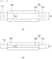
- FIG. 2 is a sectional view of a busbar assembly according to a first preferred embodiment of the present invention, cut in a vertical direction and a horizontal direction.
- the busbar assembly includes a busbar 100 and a cover member 200 configured to wrap a part of the busbar 100.
- the busbar 100 may be made of a flat copper material, and may include a first busbar 110 located at each of opposite ends and a second busbar 120 wrapped by the cover member 200, the second busbar being configured to connect the first busbars 110 located at the opposite ends to each other.
- the first busbar 110 may be connected to a terminal of a battery module adjacent thereto, and the second busbar 120 connects the first busbars 110 located at opposite sides thereof to each other through a wall configured to partition each battery module zone in a case configured to receive a battery module in a state of being wrapped by the cover member 200.
- the width W2 of the second busbar 120 may be less than the width W1 of the first busbar 110, and the height L2 of the second busbar 120 may be less than the height L1 of the first busbar 110, whereby a step may be formed between the first busbar 110 and the second busbar 120.
- the second busbar 120 is wrapped by the cover member 200. Even though fire or venting gas occurs in a direction toward the first busbar 110, therefore, it is difficult for the venting gas to be introduced between the second busbar 120 and the cover member due to the step formed between the first busbar 110 and the second busbar 120, whereby safety may be improved.
- the cover member 200 which wraps the second busbar 120 to prevent short circuit due to contact between the second busbar 120 and a metal adjacent thereto, may be made of an insulative material.
- the cover member 200 may be made of a refractory material that does not melt in the event of fire or at high temperatures.
- the cover member may be made of a material including at least one of ceramized silicone, a ceramic material, a resin mixed with a polyethylene and ethylene copolymer, mica, glass fiber woven fabric, and a mixture of mPPO and GF20.
- the movement of the cover member 200 in a longitudinal direction thereof may be restricted by the step formed between the first busbar 110 and the second busbar 120, whereby fixation force may be improved.
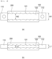
- FIG. 3 is a sectional view of a busbar assembly according to a second preferred embodiment of the present invention, cut in the vertical direction and the horizontal direction.
- the busbar assembly according to the second preferred embodiment of the present invention is identical to the busbar assembly according to the first embodiment described with reference to FIG. 2 except for the shape of a second busbar 120, and therefore a description of the same configuration will be omitted.
- At least one band-shaped protrusion 121 may be formed on an outer surface of the second busbar 120 along the perimeter of the second busbar 120, and the sectional shape of the protrusion 121 may be quadrangular.
- a plurality of protrusions 121 may be provided, and the protrusions may be spaced apart from each other by a predetermined distance to form an uneven shape.
- each protrusion 121 may block venting gas introduced between the second busbar 120 and a cover member 200, whereby the effect of blocking the movement of the venting gas may be improved, compared to when only one protrusion 121 is formed.
- the outermost protrusion 121 may be formed so as to be spaced apart from a first busbar 110.
- the reason for this is that, if the protrusion 121 is formed so as to be in tight contact with the first busbar 110, no step is formed between the first busbar 110 and the second busbar 120, whereby the effect of inhibiting the inflow of venting gas due to the step may be reduced.
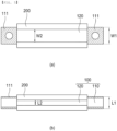
- FIG. 4 is a sectional view of a busbar assembly according to a third preferred embodiment of the present invention, cut in the vertical direction and the horizontal direction.
- the busbar assembly according to the third preferred embodiment of the present invention is identical to the busbar assembly according to the first embodiment described with reference to FIG. 2 except for the shape of a second busbar 120, and therefore a description of the same configuration will be omitted.
- At least one band-shaped protrusion 121 may be formed on an outer surface of the second busbar 120 along the perimeter of the second busbar 120.
- the sectional shape of the protrusion 121 may be right triangular, and an inclined surface of the right triangular shape inclined at a predetermined angle may be formed so as to face the middle of the second busbar 120.
- a plurality of protrusions 121 may be provided so as to be spaced apart from each other. When a plurality of protrusions 121 is formed, each protrusion 121 may block venting gas introduced between the second busbar 120 and a cover member 200, whereby the effect of blocking the movement of the venting gas may be improved, compared to when only one protrusion 121 is formed.
- the outermost protrusion 121 may be formed so as to be spaced apart from a first busbar 110.
- the reason for this is that, if the protrusion 121 is formed so as to be in tight contact with the first busbar 110, no step is formed between the first busbar 110 and the second busbar 120, whereby the effect of inhibiting the inflow of venting gas due to the step may be reduced.
- FIG. 5 is a sectional view of a busbar assembly according to a fourth preferred embodiment of the present invention, cut in the vertical direction and the horizontal direction.
- the busbar assembly according to the fourth preferred embodiment of the present invention is identical to the busbar assembly according to the first embodiment described with reference to FIG. 2 except that a metal layer 111 is formed on a first busbar 110, and therefore a description of the same configuration will be omitted.
- a metal layer 111 having a predetermined thickness may be formed on each of an upper surface and a lower surface of a first busbar 110 located at each of opposite ends.
- the metal layer 111 may be made of aluminum, and may be formed by copper clad aluminum (CCA) welding.
- CCA copper clad aluminum
- a step may be formed between the first busbar 110 and a second busbar 120, whereby it is possible to prevent venting gas from being introduced between the first busbar 120 and a cover member 200.
- the height of the first busbar 110 excluding the metal layer 111 is shown as being greater than the height of the second busbar 120 in the figure, the height of the first busbar 110 excluding the metal layer 111 may be equal to the height of the second busbar 120, since the metal layer 111 may be formed on the first busbar 110 to form a step.
- the present invention may provide a battery pack including the busbar assembly and a device having the battery pack mounted therein.
Landscapes
- Chemical & Material Sciences (AREA)
- Chemical Kinetics & Catalysis (AREA)
- Electrochemistry (AREA)
- General Chemical & Material Sciences (AREA)
- Inorganic Chemistry (AREA)
- Connection Of Batteries Or Terminals (AREA)
- Battery Mounting, Suspending (AREA)
Applications Claiming Priority (2)
| Application Number | Priority Date | Filing Date | Title |
|---|---|---|---|
| KR1020220125944A KR20240046934A (ko) | 2022-10-04 | 2022-10-04 | 화재발생으로 인한 피해를 방지할 수 있는 버스바 어셈블리 및 이를 포함하는 전지 팩 |
| PCT/KR2023/013785 WO2024076032A1 (ko) | 2022-10-04 | 2023-09-14 | 화재발생으로 인한 피해를 방지할 수 있는 버스바 어셈블리 및 이를 포함하는 전지 팩 |
Publications (2)
| Publication Number | Publication Date |
|---|---|
| EP4404370A1 true EP4404370A1 (de) | 2024-07-24 |
| EP4404370A4 EP4404370A4 (de) | 2025-03-12 |
Family
ID=90608701
Family Applications (1)
| Application Number | Title | Priority Date | Filing Date |
|---|---|---|---|
| EP23875100.2A Pending EP4404370A4 (de) | 2022-10-04 | 2023-09-14 | Sammelschienenanordnung zur verhinderung von schäden durch auftreten von feuer und batteriepack damit |
Country Status (6)
| Country | Link |
|---|---|
| US (1) | US20250038365A1 (de) |
| EP (1) | EP4404370A4 (de) |
| JP (1) | JP2024541176A (de) |
| KR (1) | KR20240046934A (de) |
| CN (1) | CN118202516A (de) |
| WO (1) | WO2024076032A1 (de) |
Families Citing this family (2)
| Publication number | Priority date | Publication date | Assignee | Title |
|---|---|---|---|---|
| KR20250164414A (ko) * | 2024-05-16 | 2025-11-25 | 주식회사 엘지에너지솔루션 | 버스바 조립체 및 이를 포함하는 전지 팩 |
| KR20260046565A (ko) * | 2024-09-30 | 2026-04-07 | 주식회사 엘지에너지솔루션 | 버스바 커버 및 이를 포함하는 배터리 팩 |
Family Cites Families (12)
| Publication number | Priority date | Publication date | Assignee | Title |
|---|---|---|---|---|
| JPS5636057Y2 (de) * | 1976-07-17 | 1981-08-25 | ||
| JPS61121663U (de) * | 1985-01-18 | 1986-07-31 | ||
| KR100946579B1 (ko) * | 2005-10-21 | 2010-03-09 | 주식회사 엘지화학 | 중대형 전지팩용 유연성 버스 바 |
| KR20150101154A (ko) | 2014-02-26 | 2015-09-03 | 엘에스전선 주식회사 | 플렉서블 버스바 |
| KR20190009120A (ko) * | 2017-07-18 | 2019-01-28 | 한국단자공업 주식회사 | 버스바조립체 및 그 제조방법 |
| KR102382386B1 (ko) * | 2018-02-09 | 2022-04-01 | 주식회사 엘지에너지솔루션 | 전류 차단부를 구비한 버스바 및 그것을 포함한 배터리 모듈 |
| KR101996444B1 (ko) * | 2018-04-25 | 2019-10-01 | 주식회사 유라코퍼레이션 | 버스바 어셈블리 |
| JP7028825B2 (ja) * | 2019-05-22 | 2022-03-02 | 本田技研工業株式会社 | 組電池 |
| KR102815964B1 (ko) * | 2019-08-12 | 2025-05-30 | 주식회사 엘지에너지솔루션 | 부분 인서트 사출을 적용한 플랙서블 버스바 |
| KR102926964B1 (ko) * | 2020-05-15 | 2026-02-11 | 주식회사 엘지에너지솔루션 | 화재 안전성이 우수한 버스바 |
| KR102567783B1 (ko) | 2021-03-08 | 2023-08-16 | 손정훈 | 어구 인양기용 구동 제어 장치 |
| CN216698651U (zh) * | 2021-11-24 | 2022-06-07 | 福建飞毛腿动力科技有限公司 | 电池中使用的软铜排结构 |
-
2022
- 2022-10-04 KR KR1020220125944A patent/KR20240046934A/ko active Pending
-
2023
- 2023-09-14 EP EP23875100.2A patent/EP4404370A4/de active Pending
- 2023-09-14 WO PCT/KR2023/013785 patent/WO2024076032A1/ko not_active Ceased
- 2023-09-14 CN CN202380013963.2A patent/CN118202516A/zh active Pending
- 2023-09-14 JP JP2024516738A patent/JP2024541176A/ja active Pending
- 2023-09-14 US US18/696,603 patent/US20250038365A1/en active Pending
Also Published As
| Publication number | Publication date |
|---|---|
| US20250038365A1 (en) | 2025-01-30 |
| CN118202516A (zh) | 2024-06-14 |
| EP4404370A4 (de) | 2025-03-12 |
| JP2024541176A (ja) | 2024-11-08 |
| WO2024076032A1 (ko) | 2024-04-11 |
| KR20240046934A (ko) | 2024-04-12 |
Similar Documents
| Publication | Publication Date | Title |
|---|---|---|
| US11777158B2 (en) | Battery module and battery pack including same | |
| EP3644403B1 (de) | Batteriemodul mit gasentladungsstruktur | |
| CN113826270B (zh) | 电池组、电子装置及车辆 | |
| US10236482B2 (en) | Battery module of improved safety and battery pack containing the same | |
| JP2023519400A (ja) | 火災抑制のための隔壁及び断熱層を備えた電池モジュール | |
| EP4404370A1 (de) | Sammelschienenanordnung zur verhinderung von schäden durch auftreten von feuer und batteriepack damit | |
| EP2293361A2 (de) | Mittelgrosses oder grosses batteriepack mit verbesserter sicherheit | |
| EP4131610A1 (de) | Batteriemodul mit brandausbreitungverhinderungsstruktur und batteriepack damit | |
| CN117280534A (zh) | 包括排放单元的二次电池 | |
| CN117616625A (zh) | 电池模块和包括该电池模块的电池组和车辆 | |
| KR102949034B1 (ko) | 배터리 모듈, 이러한 배터리 모듈을 포함하는 배터리 팩 및 이러한 배터리 팩을 포함하는 자동차 | |
| CN118523034A (zh) | 电池装置 | |
| US20250062498A1 (en) | Inter-Module Busbar Capable of Delaying Thermal Runaway Propagation and Battery Pack Including the Same | |
| US20260031456A1 (en) | Battery pack having excellent impact resistance | |
| EP4645562A1 (de) | Batteriemodul, batteriepack und fahrzeug damit | |
| EP4700957A1 (de) | Batteriemodul und batteriepack sowie fahrzeug damit | |
| US20240347851A1 (en) | Battery device and battery system including the same | |
| CN121285902A (zh) | 电池模块和包括该电池模块的电池组 | |
| KR20250178559A (ko) | 배터리 모듈, 이를 포함하는 배터리 팩 및 자동차 | |
| KR20250046804A (ko) | 배터리 모듈 | |
| CN121079839A (zh) | 电池模块、以及包括该电池模块的电池组和车辆 | |
| KR20250098756A (ko) | 이차전지모듈 | |
| KR20250147220A (ko) | 배터리 모듈 그리고 이를 포함하는 배터리 팩 및 자동차 | |
| KR20260012566A (ko) | 배터리 모듈, 이를 포함하는 배터리 팩 및 자동차 | |
| CN121569397A (zh) | 电池模块和包括该电池模块的电池组及车辆 |
Legal Events
| Date | Code | Title | Description |
|---|---|---|---|
| STAA | Information on the status of an ep patent application or granted ep patent |
Free format text: STATUS: THE INTERNATIONAL PUBLICATION HAS BEEN MADE |
|
| PUAI | Public reference made under article 153(3) epc to a published international application that has entered the european phase |
Free format text: ORIGINAL CODE: 0009012 |
|
| STAA | Information on the status of an ep patent application or granted ep patent |
Free format text: STATUS: REQUEST FOR EXAMINATION WAS MADE |
|
| 17P | Request for examination filed |
Effective date: 20240416 |
|
| AK | Designated contracting states |
Kind code of ref document: A1 Designated state(s): AL AT BE BG CH CY CZ DE DK EE ES FI FR GB GR HR HU IE IS IT LI LT LU LV MC ME MK MT NL NO PL PT RO RS SE SI SK SM TR |
|
| A4 | Supplementary search report drawn up and despatched |
Effective date: 20250211 |
|
| RIC1 | Information provided on ipc code assigned before grant |
Ipc: H01M 50/526 20210101ALI20250205BHEP Ipc: H01M 50/204 20210101ALI20250205BHEP Ipc: H01M 50/522 20210101ALI20250205BHEP Ipc: H01M 50/503 20210101ALI20250205BHEP Ipc: H01M 50/507 20210101ALI20250205BHEP Ipc: H01M 50/588 20210101ALI20250205BHEP Ipc: H01M 50/591 20210101AFI20250205BHEP |
|
| STAA | Information on the status of an ep patent application or granted ep patent |
Free format text: STATUS: EXAMINATION IS IN PROGRESS |
|
| 17Q | First examination report despatched |
Effective date: 20250902 |
|
| DAV | Request for validation of the european patent (deleted) | ||
| DAX | Request for extension of the european patent (deleted) |