EP4404352A1 - Batteriekasten, batterie und stromverbrauchende vorrichtung - Google Patents
Batteriekasten, batterie und stromverbrauchende vorrichtung Download PDFInfo
- Publication number
- EP4404352A1 EP4404352A1 EP22946471.4A EP22946471A EP4404352A1 EP 4404352 A1 EP4404352 A1 EP 4404352A1 EP 22946471 A EP22946471 A EP 22946471A EP 4404352 A1 EP4404352 A1 EP 4404352A1
- Authority
- EP
- European Patent Office
- Prior art keywords
- housing
- end cap
- battery case
- battery
- sealing
- Prior art date
- Legal status (The legal status is an assumption and is not a legal conclusion. Google has not performed a legal analysis and makes no representation as to the accuracy of the status listed.)
- Pending
Links
Images


Classifications
-
- H—ELECTRICITY
- H01—ELECTRIC ELEMENTS
- H01M—PROCESSES OR MEANS, e.g. BATTERIES, FOR THE DIRECT CONVERSION OF CHEMICAL ENERGY INTO ELECTRICAL ENERGY
- H01M50/00—Constructional details or processes of manufacture of the non-active parts of electrochemical cells other than fuel cells, e.g. hybrid cells
- H01M50/10—Primary casings; Jackets or wrappings
- H01M50/147—Lids or covers
- H01M50/166—Lids or covers characterised by the methods of assembling casings with lids
-
- H—ELECTRICITY
- H01—ELECTRIC ELEMENTS
- H01M—PROCESSES OR MEANS, e.g. BATTERIES, FOR THE DIRECT CONVERSION OF CHEMICAL ENERGY INTO ELECTRICAL ENERGY
- H01M50/00—Constructional details or processes of manufacture of the non-active parts of electrochemical cells other than fuel cells, e.g. hybrid cells
- H01M50/20—Mountings; Secondary casings or frames; Racks, modules or packs; Suspension devices; Shock absorbers; Transport or carrying devices; Holders
- H01M50/258—Modular batteries; Casings provided with means for assembling
-
- H—ELECTRICITY
- H01—ELECTRIC ELEMENTS
- H01M—PROCESSES OR MEANS, e.g. BATTERIES, FOR THE DIRECT CONVERSION OF CHEMICAL ENERGY INTO ELECTRICAL ENERGY
- H01M50/00—Constructional details or processes of manufacture of the non-active parts of electrochemical cells other than fuel cells, e.g. hybrid cells
- H01M50/10—Primary casings; Jackets or wrappings
- H01M50/102—Primary casings; Jackets or wrappings characterised by their shape or physical structure
- H01M50/103—Primary casings; Jackets or wrappings characterised by their shape or physical structure prismatic or rectangular
-
- H—ELECTRICITY
- H01—ELECTRIC ELEMENTS
- H01M—PROCESSES OR MEANS, e.g. BATTERIES, FOR THE DIRECT CONVERSION OF CHEMICAL ENERGY INTO ELECTRICAL ENERGY
- H01M50/00—Constructional details or processes of manufacture of the non-active parts of electrochemical cells other than fuel cells, e.g. hybrid cells
- H01M50/10—Primary casings; Jackets or wrappings
- H01M50/147—Lids or covers
- H01M50/148—Lids or covers characterised by their shape
- H01M50/15—Lids or covers characterised by their shape for prismatic or rectangular cells
-
- H—ELECTRICITY
- H01—ELECTRIC ELEMENTS
- H01M—PROCESSES OR MEANS, e.g. BATTERIES, FOR THE DIRECT CONVERSION OF CHEMICAL ENERGY INTO ELECTRICAL ENERGY
- H01M50/00—Constructional details or processes of manufacture of the non-active parts of electrochemical cells other than fuel cells, e.g. hybrid cells
- H01M50/10—Primary casings; Jackets or wrappings
- H01M50/147—Lids or covers
- H01M50/148—Lids or covers characterised by their shape
- H01M50/152—Lids or covers characterised by their shape for cells having curved cross-section, e.g. round or elliptic
-
- H—ELECTRICITY
- H01—ELECTRIC ELEMENTS
- H01M—PROCESSES OR MEANS, e.g. BATTERIES, FOR THE DIRECT CONVERSION OF CHEMICAL ENERGY INTO ELECTRICAL ENERGY
- H01M50/00—Constructional details or processes of manufacture of the non-active parts of electrochemical cells other than fuel cells, e.g. hybrid cells
- H01M50/20—Mountings; Secondary casings or frames; Racks, modules or packs; Suspension devices; Shock absorbers; Transport or carrying devices; Holders
- H01M50/204—Racks, modules or packs for multiple batteries or multiple cells
- H01M50/207—Racks, modules or packs for multiple batteries or multiple cells characterised by their shape
- H01M50/209—Racks, modules or packs for multiple batteries or multiple cells characterised by their shape adapted for prismatic or rectangular cells
-
- H—ELECTRICITY
- H01—ELECTRIC ELEMENTS
- H01M—PROCESSES OR MEANS, e.g. BATTERIES, FOR THE DIRECT CONVERSION OF CHEMICAL ENERGY INTO ELECTRICAL ENERGY
- H01M50/00—Constructional details or processes of manufacture of the non-active parts of electrochemical cells other than fuel cells, e.g. hybrid cells
- H01M50/20—Mountings; Secondary casings or frames; Racks, modules or packs; Suspension devices; Shock absorbers; Transport or carrying devices; Holders
- H01M50/233—Mountings; Secondary casings or frames; Racks, modules or packs; Suspension devices; Shock absorbers; Transport or carrying devices; Holders characterised by physical properties of casings or racks, e.g. dimensions
- H01M50/24—Mountings; Secondary casings or frames; Racks, modules or packs; Suspension devices; Shock absorbers; Transport or carrying devices; Holders characterised by physical properties of casings or racks, e.g. dimensions adapted for protecting batteries from their environment, e.g. from corrosion
-
- H—ELECTRICITY
- H01—ELECTRIC ELEMENTS
- H01M—PROCESSES OR MEANS, e.g. BATTERIES, FOR THE DIRECT CONVERSION OF CHEMICAL ENERGY INTO ELECTRICAL ENERGY
- H01M50/00—Constructional details or processes of manufacture of the non-active parts of electrochemical cells other than fuel cells, e.g. hybrid cells
- H01M50/20—Mountings; Secondary casings or frames; Racks, modules or packs; Suspension devices; Shock absorbers; Transport or carrying devices; Holders
- H01M50/244—Secondary casings; Racks; Suspension devices; Carrying devices; Holders characterised by their mounting method
-
- H—ELECTRICITY
- H01—ELECTRIC ELEMENTS
- H01M—PROCESSES OR MEANS, e.g. BATTERIES, FOR THE DIRECT CONVERSION OF CHEMICAL ENERGY INTO ELECTRICAL ENERGY
- H01M50/00—Constructional details or processes of manufacture of the non-active parts of electrochemical cells other than fuel cells, e.g. hybrid cells
- H01M50/20—Mountings; Secondary casings or frames; Racks, modules or packs; Suspension devices; Shock absorbers; Transport or carrying devices; Holders
- H01M50/249—Mountings; Secondary casings or frames; Racks, modules or packs; Suspension devices; Shock absorbers; Transport or carrying devices; Holders specially adapted for aircraft or vehicles, e.g. cars or trains
-
- H—ELECTRICITY
- H01—ELECTRIC ELEMENTS
- H01M—PROCESSES OR MEANS, e.g. BATTERIES, FOR THE DIRECT CONVERSION OF CHEMICAL ENERGY INTO ELECTRICAL ENERGY
- H01M50/00—Constructional details or processes of manufacture of the non-active parts of electrochemical cells other than fuel cells, e.g. hybrid cells
- H01M50/20—Mountings; Secondary casings or frames; Racks, modules or packs; Suspension devices; Shock absorbers; Transport or carrying devices; Holders
- H01M50/262—Mountings; Secondary casings or frames; Racks, modules or packs; Suspension devices; Shock absorbers; Transport or carrying devices; Holders with fastening means, e.g. locks
- H01M50/264—Mountings; Secondary casings or frames; Racks, modules or packs; Suspension devices; Shock absorbers; Transport or carrying devices; Holders with fastening means, e.g. locks for cells or batteries, e.g. straps, tie rods or peripheral frames
-
- H—ELECTRICITY
- H01—ELECTRIC ELEMENTS
- H01M—PROCESSES OR MEANS, e.g. BATTERIES, FOR THE DIRECT CONVERSION OF CHEMICAL ENERGY INTO ELECTRICAL ENERGY
- H01M50/00—Constructional details or processes of manufacture of the non-active parts of electrochemical cells other than fuel cells, e.g. hybrid cells
- H01M50/20—Mountings; Secondary casings or frames; Racks, modules or packs; Suspension devices; Shock absorbers; Transport or carrying devices; Holders
- H01M50/271—Lids or covers for the racks or secondary casings
-
- H—ELECTRICITY
- H01—ELECTRIC ELEMENTS
- H01M—PROCESSES OR MEANS, e.g. BATTERIES, FOR THE DIRECT CONVERSION OF CHEMICAL ENERGY INTO ELECTRICAL ENERGY
- H01M50/00—Constructional details or processes of manufacture of the non-active parts of electrochemical cells other than fuel cells, e.g. hybrid cells
- H01M50/20—Mountings; Secondary casings or frames; Racks, modules or packs; Suspension devices; Shock absorbers; Transport or carrying devices; Holders
- H01M50/296—Mountings; Secondary casings or frames; Racks, modules or packs; Suspension devices; Shock absorbers; Transport or carrying devices; Holders characterised by terminals of battery packs
-
- Y—GENERAL TAGGING OF NEW TECHNOLOGICAL DEVELOPMENTS; GENERAL TAGGING OF CROSS-SECTIONAL TECHNOLOGIES SPANNING OVER SEVERAL SECTIONS OF THE IPC; TECHNICAL SUBJECTS COVERED BY FORMER USPC CROSS-REFERENCE ART COLLECTIONS [XRACs] AND DIGESTS
- Y02—TECHNOLOGIES OR APPLICATIONS FOR MITIGATION OR ADAPTATION AGAINST CLIMATE CHANGE
- Y02E—REDUCTION OF GREENHOUSE GAS [GHG] EMISSIONS, RELATED TO ENERGY GENERATION, TRANSMISSION OR DISTRIBUTION
- Y02E60/00—Enabling technologies; Technologies with a potential or indirect contribution to GHG emissions mitigation
- Y02E60/10—Energy storage using batteries
Definitions
- the present application relates to the technical field of electric vehicles, and in particular to a battery case, a battery and a power consuming device.
- the battery includes a plurality of battery modules and a battery case.
- the plurality of battery modules are accommodated in the battery case to prevent liquid or other foreign matter from affecting charging or discharging of the battery modules.
- An existing battery case includes a housing and an end cap.
- the end cap is connected and fixed to the housing by means of a bolt, and a sealing gasket is arranged between the end cap and the housing to seal the battery case.
- a sealing gasket is arranged between the end cap and the housing to seal the battery case.
- the present application provides a battery case, a battery and a power consuming device, which can solve the problem that a sealing structure occupies the space in a height direction inside the battery case.
- a battery case in a first aspect of the present application, includes a housing, an end cap and a sealing member.
- the housing has an open end.
- the end cap fits with the housing and covers the open end, the end cap is provided with a groove and a sealing region, the groove is provided in a surface of the end cap facing away from the housing, and the sealing region is arranged on a peripheral surface of the end cap and corresponding to an inner side wall of the groove.
- the sealing member is arranged between an inner wall of the housing and the sealing region.
- the end cap when the end cap is connected and fixed to the housing, the end cap closes the open end of the housing, and a part of a body of the end cap is arranged in the open end of the housing.
- the sealing member is correspondingly arranged between the sealing region on an outer side of the groove and the inner wall of the housing, and the sealing between the end cap and the housing is realized by using the sealing member.
- a sealing structure formed between the sealing region, the sealing member and the inner wall of the housing is located in a circumferential direction of the end cap, which reduces the space in a height direction occupied by the sealing structure inside the battery case, so that the space inside the battery case is increased, the PACK grouping efficiency of the battery case is improved, and the battery case can be applied to application scenarios in which the height is limited.
- the groove is provided in the height direction of the housing, and the dimension of the sealing region in the height direction of the housing is less than or equal to the depth of the groove.
- the groove is formed in the end cap, and its depth direction is arranged in the height direction of the housing.
- the sealing region is formed on an edge of the end cap at the position where the edge of the end cap corresponds to a side wall of the groove. Controlling the dimension of the sealing region in the height direction of the housing enables the space occupied by the sealing structure in the height direction of the battery case to be further reduced while ensuring the sealing effect between the end cap and the housing, so that the internal space inside the battery case is increased.
- the dimension of the sealing region in the height direction of the housing is 10 mm, and the distance between the sealing region and the inner wall of the housing is 10 mm.
- the sealing region is sized, so that the space occupied by the sealing structure in the height direction of the battery case is effectively reduced, and the internal space of the battery case is increased, while ensuring the sealing effect between the end cap and the housing.
- a side wall of the groove is connected and fixed to the housing by means of TOX riveting.
- the side wall of the groove is connected and fixed to the inner wall of the housing by means of TOX riveting, and the sealing member is sandwiched between the inner wall of the housing and the sealing region of the end cap.
- At least one TOX riveting point of the side wall of the groove and the housing is provided, the sealing member is provided with avoidance holes with the same number as the TOX riveting points, and the avoidance holes corresponds to the TOX riveting points in a one-to-one basis.
- the sealing member is provided with the avoidance holes, and when the end cap is connected and fixed to the housing, the avoidance holes are arranged corresponding to the TOX riveting points, which ensures that the end cap and the housing can be riveted effectively, and further ensures the strength of connection and fixation between the end cap and the housing.
- a plurality of TOX riveting points are provided, and all the TOX riveting points are arranged at intervals in a circumferential direction of the open end.
- the plurality of TOX riveting points are provided to further increase riveting positions between the end cap and the housing, so that the strength of connection between the end cap and the housing is further enhanced.
- a first connecting structure is provided on an edge of the end cap, a second connecting structure is provided on a peripheral surface of the open end, and the first connecting structure fits with the second connecting structure to connect and fix the end cap to the housing.
- the second connecting structure is located on an outer side of the housing, and the first connecting structure fits with the second connecting structure to realize the connection and fixation between the end cap and the housing.
- the connection position between the end cap and the housing is provided on the outer side of the battery case, which not only facilitates the connection and fixation between the end cap and the housing, but also further avoids occupying the internal space of the battery case.
- the second connecting structure is of a plate-like structure in snap fit with the first connecting structure, and a side of the plate-like structure facing the bottom of the housing is arranged at a preset angle a with respect with a side face of the housing, wherein 0° ⁇ a ⁇ 90°.
- the second connecting structure is configured as the plate-like structure, the angle a between the plate-like structure and the outer surface of the housing is set such that the second connecting structure of the plate-like structure is inclined to the side of the bottom of the housing, and when the first connecting structure fits with the second connecting structure, the strength of the first connecting structure and the second connecting structure is ensured.
- the first connecting structure is of a hook structure.
- the first connecting structure is configured as the hook structure, so that the end cap is connected and fixed to the housing so long as the hook structure is hooked onto the second connecting structure of the plate-like structure.
- the hook structure has a simple structure and a low manufacturing cost, and facilitates the assembly when the end cap is connected and fixed to the housing.
- the hook structure is provided with a notch at a corner of the end cap.
- the first connecting structure of the hook structure is arranged in the circumferential direction of the end cap, the end cap has the corner, and the hook structure is provided with the notch at the corner, so that the hook structure is prevented from interfering at the corner, and the fit between the first connecting structure and the second connecting structure is ensured.
- the first connecting structure is of an edge-folded structure.
- the first connecting structure is configured as the edge-folded structure.
- the first connecting structure is edge-folded by using an edge folding apparatus after the end cap, the sealing member and the housing are mounted in place, to connect and fix the first connecting structure to the second connecting structure.
- the first connecting structure is configured as the edge-folded structure, which improves the strength of connection between the first connecting structure and the second connecting structure, and further ensures the strength of connection between the end cap and the housing.
- the edge-folded structure is provided with a notch at a corner of the end cap.
- the first connecting structure of the edge-folded structure is arranged in the circumferential direction of the end cap, the end cap has the corner, and the edge-folded structure is provided with the notch at the corner, so that the edge-folded structure is prevented from interfering at the corner, and the fit between the first connecting structure and the second connecting structure is ensured.
- an abutting structure is provided in the housing, the abutting structure is arranged in the circumferential direction of the open end, and the sealing member abuts against the abutting structure.
- a battery in a second aspect of the present application, includes a battery case as described above.
- a power consuming device in a third aspect of the present application, includes a battery as described above.
- a plurality of means two or more (including two), similarly the term “a plurality of groups” means two or more groups (including two groups), and the term “a plurality of pieces” means two or more pieces (including two pieces).
- the technical terms such as “mount”, “couple”, “connect”, and “fix” should be understood in a broad sense, for example, they may be a fixed connection, a detachable connection, or an integrated connection; may be a mechanical connection or an electric connection; and may be a direct connection or an indirect connection by means of an intermediate medium, or may be internal communication between two elements or interaction between the two elements.
- mount may be a fixed connection, a detachable connection, or an integrated connection
- traction batteries are used more and more widely.
- the traction batteries are not only used in energy storage power systems such as hydroelectric power plants, thermal power plants, wind power plants and solar power plants, but also widely used in electric transportation means such as electric bicycles, electric motorcycles, and electric vehicles and in many fields such as military equipment and aerospace. With the continuous expansion of the application field of traction batteries, market demand for traction batteries is also expanding.
- an end cap of an existing battery case is connected and fixed to a housing of the battery case by means of a bolt, and a sealing gasket is arranged between the end cap and the housing to seal the battery case.
- a sealing gasket is arranged between the end cap and the housing to seal the battery case.
- the end cap may be provided with a groove, and a sealing region may be provided on the end cap on the outer side of a side wall of the groove.
- the end cap closes an open end of the housing, and a part of a body of the end cap is arranged in the open end of the housing.
- a sealing member is correspondingly arranged between the sealing region on the outer side of the groove and an inner wall of the housing, and the sealing between the end cap and the housing is realized by using the sealing member.
- a sealing structure formed between the sealing region, the sealing member and the inner wall of the housing is located in a circumferential direction of the end cap, which reduces the space in a height direction occupied by the sealing structure inside the battery case, so that the space inside the battery case is increased, the PACK grouping efficiency of the battery case is improved, and the battery case can be applied to application scenarios in which the height is limited.
- the battery cell disclosed in the embodiments of the present application may be used in, but is not limited to, a power consuming device, such as a vehicle, a ship, or an aircraft.
- a power supply system provided with the power consuming device composed of a battery cell, a battery and the like disclosed in the present application may be used.
- the embodiments of the present application provide a power consuming device using a battery as a power supply.
- the power consuming device may be, but is not limited to, a mobile phone, a tablet, a laptop, an electric toy, an electric tool, an electric scooter, an electric vehicle, a ship, a spacecraft, etc.
- the electric toy may include a stationary or mobile electric toy, such as a game console, an electric vehicle toy, an electric ship toy, and an electric airplane toy.
- the spacecraft may include an airplane, a rocket, a space shuttle, a spaceship, etc.
- FIG. 1 is a schematic structural diagram of a vehicle 1000 according to some embodiments of the present application.
- the vehicle 1000 may be a fuel vehicle, a gas vehicle, or a new energy vehicle.
- the new energy vehicle may be a battery electric vehicle, a hybrid electric vehicle, or an extended-range vehicle, etc.
- a battery 100 is provided inside the vehicle 1000, and the battery 100 may be arranged at the bottom, the front or the back of the vehicle 1000.
- the battery 100 may be configured to supply power to the vehicle 1000.
- the battery 100 may be used as a power supply for operating the vehicle 1000.
- the vehicle 1000 may further include a controller 200 and a motor 300.
- the controller 200 is configured to control the battery 100 to supply power to the motor 300, for example, to meet working power requirements during starting, navigation and traveling of the vehicle 1000.
- the battery 100 can not only serve as a power supply for operating the vehicle 1000, but also serve as a power supply for driving the vehicle 1000, instead of or partially instead of fuel or natural gas, to provide driving power for the vehicle 1000.
- the battery 100 may include a plurality of battery cells 11, the battery cell 11 referring to a minimum unit that constitutes a battery module 10 or the battery 100.
- the plurality of battery cells 11 may be connected in series and/or in parallel via electrode terminals 111a for various applications.
- the battery 100 mentioned in the present application includes the battery module 10 or a battery pack.
- the plurality of battery cells 11 may be connected in series or in parallel or in series-parallel.
- the series-parallel connection refers to a combination of serial connection and parallel connection.
- the battery 100 may also be referred to as a battery pack.
- the plurality of battery cells 11 may directly form a battery pack, or may first form battery modules 10, and the battery modules 10 may then form a battery pack.
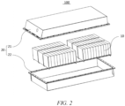
- FIG. 2 shows a schematic structural diagram of a battery 100 according to an embodiment of the present application.
- the battery 100 may include a plurality of battery modules 10 and a battery case 20.
- the plurality of battery modules 10 are accommodated in the battery case 20.
- the battery case 20 is used to accommodate the battery cells 11 or the battery modules 10, so as to prevent liquid or other foreign matter from affecting charging or discharging of the battery cells 11.
- the battery case 20 may be of a simple three-dimensional structure such as an individual cuboid, cylinder or sphere, or of a complex three-dimensional structure composed of simple three-dimensional structures such as a cuboid, a cylinder or a sphere, which is not limited in the embodiments of the present application.
- a material of the battery case 20 may be an alloy material such as aluminum alloy and ferroalloy, or a polymer material such as polycarbonate and polyisocyanurate foam plastic, or a composite material such as a combination of glass fiber and epoxy resin, which is not limited in the embodiments of the present application.
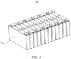
- FIG. 3 shows a schematic structural diagram of a battery module 10 according to an embodiment of the present application.
- the battery module 10 may include a plurality of battery cells 11.
- the plurality of battery cells 11 may be first connected in series or in parallel or in series-parallel to form a battery module 10, and the plurality of battery modules 10 may be then connected in series or in parallel or in series-parallel to form a battery.
- the battery cell 11 may include a lithium-ion battery cell, a sodium-ion battery cell, a magnesium-ion battery cell, etc., which is not limited in the embodiments of the present application.
- the battery cell 11 may be cylindrical, flat, cuboid or in another shape, which is not limited in the embodiments of the present application.
- the battery cells 11 are generally divided into three types depending on the way of package: cylindrical battery cells, prismatic battery cells and pouch battery cells, which is also not limited in the embodiments of the present application.
- the battery cell 11 refers to the minimum unit of the battery 100. As shown in FIG. 4 , the battery cell 11 includes a cell assembly 113.
- a cover 111 refers to a component that covers an opening of a shell body 112 to isolate an internal environment of the battery cell 11 from an external environment.
- the end cap 111 may be provided with functional components such as an electrode terminal 111a, and the electrode terminal 111a may be electrically connected to the cell assembly 113 for outputting or inputting electric energy of the battery cell 11.
- the shell body 112 is an assembly for fitting with the cover 111 to form the internal environment of the battery cell 11, wherein the formed internal environment may be used for accommodating the cell assembly 113, an electrolyte solution (not shown in the figure) and other components.
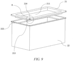
- the battery case 20 may include an end cap 21, a sealing member and a housing 22.
- the end cap 21 and the housing 22 are fitted together in a covering manner and the sealing member is arranged between the end cap 21 and the housing 22.
- a space for accommodating the battery cell is jointly defined by the end cap 21 and the housing 22.
- the joint between the end cap 21 and the housing 22 is sealed by using the sealing member.
- the end cap 21 refers to a component that covers an opening of the housing 22 to isolate an internal environment of the battery from an external environment.
- the end cap 21 may be shaped to adapt to the shape of the housing 22 so as to fit with the housing 22.
- the end cap 21 may be made of a material with certain hardness and strength (such as aluminum alloy or rigid plastics), and thus the end cap 21 is less prone to deformation when being pressed or collided, so that the battery can have a higher structural strength, and safety performance can also be improved.
- the housing 22 is an assembly that is configured to fit with the end cap 21 to form the internal environment of the battery, wherein the formed internal environment may be used for accommodating the battery module 10 and other components.
- the housing 22 and the end cap 21 may be independent components, an opening may be provided in the housing 22, and the end cap 21 covers the opening at the opening to form the internal environment of the battery cell.
- the end cap 21 and the housing 22 may also be integrated with each other.
- the end cap 21 and the housing 22 may form a common connection face before other components are inserted into the housing.
- the end cap 21 covers the housing 22.
- the housing 22 may be of various shapes and various sizes, for example, in the shape of a cuboid, a square, etc.
- the shape of the housing 22 may be determined according to the specific shape and size of the battery module.
- the housing 22 may be made of various materials, such as copper, iron, aluminum, stainless steel, an aluminum alloy, plastic, which is not particularly limited in the embodiments of the present application.
- the sealing member 23 is a component for sealing the joint between the housing 22 and the end cap 21.
- the sealing member 23 is a flexible member. After the end cap 21 and the housing 22 are assembled and fixed, the sealing member 23 abuts against each of an inner wall of the housing 22 and a sealing region and deforms (elastically deforms), thus ensuring the sealing effect between the end cap 21 and the housing 22 and further preventing the external environment from adversely affecting the interior of the battery case 20.
- the sealing member 23 may be a rubber ring or a silicone ring, etc.
- the sealing member 23 is configured as a rubber ring or a silicone ring to ensure good sealing performance of the sealing member 23 and prevent deterioration of the sealing of the battery case 20 due to aging of the sealing member 23.
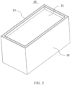
- the battery case 20 includes a housing 22, an end cap 21 and a sealing member 23.
- the housing 22 has an open end.
- the end cap 21 fits with the housing 22 and covers the open end.
- the end cap 21 is provided with a groove 211 and a sealing region 212.
- the groove 211 is provided in a surface of the end cap 21 facing away from the housing 22, and the sealing region 212 is arranged on a peripheral surface of the end cap 21 and corresponding to an inner side wall of the groove 211.
- the sealing member 23 is arranged between the inner wall of the housing 22 and the sealing region 212.
- the end cap 21 when the end cap 21 is connected and fixed to the housing 22, the end cap 21 closes the open end of the housing 22, and a part of a body of the end cap 21 is arranged in the open end of the housing 22.
- the sealing member 23 is correspondingly arranged between the sealing region 212 on an outer side of the groove 211 and the inner wall of the housing 22, and the sealing between the end cap 21 and the housing 22 is realized by using the sealing member 23.
- a sealing structure formed between the sealing region 212, the sealing member 23 and the inner wall of the housing 22 is located in a circumferential direction of the end cap 21, which reduces the space in a height direction occupied by the sealing structure inside the battery case 20, so that the space inside the battery case 20 is increased, the PACK grouping efficiency of the battery case 20 is improved and the battery case 20 can be applied to application scenarios in which the height is limited.
- the sealing region 212 is arranged in the circumferential direction of the end cap 21, and the sealing region 212 extends along the circumference of the end cap 21.
- the sealing region 212 is formed on an edge of the end cap 21 and corresponds to a side wall of the groove 211. After the end cap 21 fits with the housing 22, the sealing region 212 enters the housing 22 from the open end of the housing 22.
- the sealing member 23 is arranged between the sealing region 212 and the inner wall of the housing 22. Compared with the fact that the existing sealing member 23 arranged below the end cap 21, the sealing structure formed by the sealing member 23 enables the space occupied in a height direction of the housing 22 to be reduced, so that the PACK grouping efficiency of the battery case 20 is improved and the battery case 20 can be applied to application scenarios in which the height is limited.
- the groove 211 is provided in the height direction of the housing 22, and the dimension of the sealing region 212 in the height direction of the housing 22 is less than or equal to the depth of the groove 211.
- the groove 211 is provided in a side face of the end cap 21 facing away from the housing 22, and a depth direction of the groove 211 is arranged in the height direction of the housing 22.
- the sealing region 212 is formed on the edge of the end cap 21 at the position where the edge of the end cap 21 corresponds to the side wall of the groove 211. Controlling the dimension of the sealing region 212 in the height direction of the housing 22 enables the space occupied by the sealing structure in the height direction of the battery case 20 to be further reduced while ensuring the sealing effect between the end cap 21 and the housing 22, so that the internal space inside the battery case 20 is increased.
- the end cap 21 is a rectangular plate
- the groove 211 is provide in one side face of the rectangular plate (the groove 211 may be provided by punching a plate-like part or removing a material (for example, the groove 211 is milled by a milling cutter))
- the sealing region 212 is formed on the edge of the rectangular plate and corresponds to the side wall of the groove 211.
- the dimension of the sealing region 212 in the height direction of the housing 22 is less than or equal to the depth of the groove 211 (the dimension of the groove 211 in the height direction of the housing 22). Controlling the dimension of the sealing region 212 in the height direction of the housing 22 enables the edge of the end cap 21 to fully meet the sealing requirements, which in turn ensures the sealing of the battery case 20.
- sealing region 212 is adapted to the structure of the sealing member 23, that is, the sealing region 212 is sized to meet the requirements for abutting against the sealing member 23 and sealing.
- the dimension of the sealing region in the height direction of the housing is 10 mm, and the distance between the sealing region and the inner wall of the housing is 10 mm.
- the sealing region is sized, so that the space occupied by the sealing structure in the height direction of the battery case is effectively reduced, and the internal space of the battery case is increased, while ensuring the sealing effect between the end cap and the housing.
- the side wall of the groove 211 is connected and fixed to the housing 22 by means of TOX riveting (also called rivetless riveting).
- the end cap 21 and the sealing member 23 are mounted in place at the open end of the housing 22, the side wall of the groove 211 is riveted and fixed to the housing 22 are by using a TOX riveting apparatus, and the sealing member 23 is sandwiched between the inner wall of the housing 22 and the sealing region 212 of the end cap 21.
- TOX riveting the connection strength is high, which ensures the sealing effect between the end cap 21 and the housing 22, and at the same time, it is easy to assemble the end cap 21 and the housing 22, so that the production efficiency can be effectively improved.
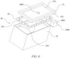
- a lower TOX die 2002 of a TOX die 2000 is arranged in the groove 211 of the end cap 21 and an upper TOX die 2001 is arranged on an outer side of the housing 22.
- the lower TOX die 2002 abuts against the side wall of the groove 211, and the upper TOX die 2001 is driven to rivet from the outer side of the housing 22 to one side of the end cap 21, thereby riveting the housing 22 and the end cap 21 together.
- end cap 21 is connected and fixed to the housing 22 by means of TOX riveting, and by means of riveting from the housing 22 to one side of the side wall of the groove 211, formation of a protrusion structure on an outer surface of the battery case 20 is prevented, which in turn ensures variations of external dimensions of the battery case 20, so that the battery case 20 can meet the use requirements in various application scenarios.
- the connecting structure between the end cap 21 and the housing 22 is arranged in a direction perpendicular to the height direction of the housing 22, which further prevents the connecting and fixing structure from occupying the space in the height direction of the housing 22, so that the internal space of the battery case 20 further improves the PACK grouping efficiency of the battery case 20, and the battery case 20 can be applied to application scenarios in which the height is limited.
- At least one TOX riveting point of the side wall of the groove 211 and the housing 22 is provided, the sealing member 23 is provided with avoidance holes 231 with the same number as the TOX riveting points, and the avoidance holes 231 corresponds to the TOX riveting points in a one-to-one basis.
- the end cap 21 is connected and fixed to the housing 22 by means of TOX riveting, and the end cap 21 is connected and fixed to the housing 22 by using at least one TOX riveting point.
- the avoidance holes 231 are arranged corresponding to the TOX riveting points, which ensures that in the process of TOX riveting, the structure at the riveting point passes through the avoidance hole 231 and is riveted and fixed, thereby ensuring that the end cap 21 and the housing 22 can be riveted effectively, and further ensuring the strength of connection and fixation between the end cap 21 and the housing 22.
- the avoidance hole 231 is provided, so that the sealing member 23 can be prevented from influencing the process of TOX riveting, which ensures the strength and stability of the riveting position.
- the avoidance hole 231 may be a circular hole, a square hole, a triangular hole or a hole in other shapes. As shown in FIG. 6 , in an embodiment of the present application, the avoidance hole 231 is a circular hole, the aperture of the circular hole being greater than or equal to the size of the riveting point.
- a plurality of TOX riveting points are provided, and all the TOX riveting points are arranged at intervals in a circumferential direction of the open end.
- the plurality of TOX riveting points are provided, and all the TOX riveting points are arranged at intervals in a circumferential direction (a circumferential direction of the open end of the housing 22) of the side wall of the groove 211.
- the plurality of TOX riveting points are provided to further increase riveting positions between the end cap 21 and the housing 22, so that the strength of connection between the end cap 21 and the housing 22 is further enhanced and the sealing between the end cap 21 and the housing 22 is further ensured.
- a first connecting structure 213 is provided on the edge of the end cap 21, a second connecting structure 222 is provided on a peripheral surface of the open end, and the first connecting structure 213 fits with the second connecting structure 222 to connect and fix the end cap 21 to the housing 22.
- the first connecting structure 213 is arranged on the end cap 21, and the second connecting structure 222 is arranged on the housing 22.
- the end cap 21 and the sealing member 23 are mounted in place at the open end of the housing 22, and the connection and fixation between the end cap 21 and the housing 22 are realized by means of the fit between the first connecting structure 213 and the second connecting structure 222.
- the second connecting structure 222 is located on the outer side of the housing 22, and the first connecting structure 213 fits with the second connecting structure 222 to realize the connection and fixation between the end cap 21 and the housing 22.
- the connecting position between the end cap 21 and the housing 22 is provided on the outer side of the battery case 20, which not only facilitates the connection and fixation between the end cap 21 and the housing 22, but also avoids occupying the internal space of the battery case 20.
- the second connecting structure 222 is of a plate-like structure in snap fit with the first connecting structure 213, and a side of the plate-like structure facing the bottom of the housing 22 is arranged at a preset angle a with respect to a side face of the housing 22, wherein 0° ⁇ a ⁇ 90°.
- the second connecting structure 222 is arranged on the outer surface of the housing 22, and the second connecting structure 222 of the plate-like structure protrudes outwards from the outer surface of the housing 22.
- the second connecting structure 222 is configured as the plate-like structure, the angle a between the plate-like structure and the outer surface of the housing 22 is set such that the second connecting structure 222 of the plate-like structure is inclined to the side of the bottom of the housing 22, and when the first connecting structure 213 fits with the second connecting structure 222, the strength of the first connecting structure 213 and the second connecting structure 222 is ensured.
- the second connecting structure 222 is configured as the plate-like structure to facilitate the connection and fixation between the first connecting structure 213 and the second connecting structure 222, thus facilitating the assembly of the battery case 20 and effectively improving the production efficiency.
- the second connecting structure 222 of the plate-like structure may be a structure integrated with the housing 22, or a structure separated from the housing 22.
- simultaneous processing and manufacturing e.g., cast molding or stamp molding
- the integrated structure has a high strength, which ensures the strength and stability of connection between the second connecting structure 222 and the housing 22; and in the case where the second connecting structure 222 is separated from the housing 22, the second connecting structure 222 and the housing 22 are processed and manufactured separately, and then the second connecting structure 222 is connected and fixed to the housing 22 by means of welding or bonding, so that the separated structure facilitates processing and can effectively improve the processing efficiency.
- the preset angle a between the housing 22 and the plate-like structure may be 30°, 40°, 50°, 60°, 70°, 80° ... 90°. In the present application, the preset angle a is 90°.
- the first connecting structure 213 may be of various structures.
- the first connecting structure 213 is of a hook structure.
- the first connecting structure 213 is configured as the hook structure, so that the end cap 21 is connected and fixed to the housing 22 so long as the hook structure is hooked onto the second connecting structure 222 of the plate-like structure.
- the hook structure has a simple structure and a low manufacturing cost, and facilitates the assembly when the end cap 21 is connected and fixed to the housing 22.
- first connecting structure 213 of the hook structure is arranged on the edge of the end cap 21, and when the end cap 21 is connected and fixed to the housing 22, an external force drives the hook structure to elastically deform. After the hook structure passes over the second connecting structure 222 of the plate-like structure, the end cap 21 is mounted in place on the housing 22, the external force is removed, the hook structure restores from the elastic deformation, and the hook structure is hooked onto the plate-like structure, thus realizing the fit between the first connecting structure 213 and the second connecting structure 222.
- the dimension of the hook structure is less than or equal to the dimension of the plate-like structure, so that the strength of engagement between the hook structure and the plate-like structure is ensured, which ensures the strength and stability of connection between the end cap 21 and the housing 22.
- the hook structure is adapted to the plate-like structure.
- the plate-like structure extends along the circumference of the housing 22.
- the plate-like structure may be of a continuous or discontinuous structure in the circumferential direction of the housing 22.
- the hook structure may also be of a continuous or discontinuous structure in the circumferential direction of the housing 22.
- the hook structure is provided with a notch 214 at a corner of the end cap 21.
- the housing 22 is of a rectangular structure
- the end cap 21 is also of a rectangular structure.
- the first connecting structure 213 of the hook structure is arranged in the circumferential direction of the end cap 21, the end cap 21 has the corner, and the hook structure is provided with the notch 214 at the corner, so that the hook structure is prevented from interference at the corner, which ensures the fit between the first connecting structure 213 and the second connecting structure 222.
- the hook structure is provided with the notch 214 at the corner of the end cap 21, which can prevent the end cap 21 from breakage due to stress concentration at the corner.
- the first connecting structure 213 is of an edge-folded structure.
- the first connecting structure 213 is of a plate-like structure; and in the case where the end cap 21 is connected and fixed to the housing 22, the first connecting structure 213 is bent by using an edge folding apparatus after the end cap 21, the sealing member 23 and the housing 22 are mounted in place, such that the first connecting structure 213 of the plate-like structure is bent relative to the second connecting structure 222 and surround the edge of the second connecting structure 222, forming an edge-folded structure to connect and fix the first connecting structure 213 to the second connecting structure 222.
- the first connecting structure 213 is configured as the edge-folded structure, which improves the strength of connection between the first connecting structure 213 and the second connecting structure 222 and further ensures the strength of connection between the end cap 21 and the housing 22.
- the first connecting structure 213 of the edge-folded structure is arranged on the edge of the end cap 21, and when the end cap 21 is connected and fixed to the housing 22, the edge-folded structure is arranged corresponding to the second connecting structure 222 of the plate-like structure.
- the edge-folded structure is edge-folded by using the edge folding apparatus, so that the edge-folded structure is formed on the outer side of the plate-like structure to realize the connection between the first connecting structure 213 and the second connecting structure 222, which in turn realizes the connection and fixation between the end cap 21 to the housing 22.
- the dimension of the edge-folded structure is less than or equal to the dimension of the plate-like structure, so that the strength of connection between the edge-folded structure and the plate-like structure is ensured, which ensures the strength and stability of connection between the end cap 21 and the housing 22.
- edge-folded structure is adapted to the plate-like structure.
- the plate-like structure extends along the circumference of the housing 22.
- the plate-like structure may be of a continuous or discontinuous structure in the circumferential direction of the housing 22.
- the edge-folded structure may also be of a continuous or discontinuous structure in the circumferential direction of the housing 22.
- the edge-folded structure is provided with a notch 214 at a corner of the end cap 21.
- the housing 22 is of a rectangular structure
- the end cap 21 is also of a rectangular structure.
- the first connecting structure 213 of the edge-folded structure is arranged in the circumferential direction of the end cap 21, the end cap 21 has the corner, and the edge-folded structure is provided with the notch 214 at the corner, so that the edge-folded structure is prevented from interference at the corner, which ensures the fit between the first connecting structure 213 and the second connecting structure 222.
- edge-folded structure is provided with the notch 214 at the corner of the end cap 21, which can prevent the end cap 21 from breakage due to stress concentration at the corner.
- an abutting structure 221 is provided in the housing 22, the abutting structure 221 is arranged in the circumferential direction of the open end, and the sealing member 23 abuts against the abutting structure 221.
- the abutting structure 221 is arranged on an inner side wall of the housing 22 and close to the open end of the housing 22.
- the sealing member 23 is first arranged in the housing 22 and abuts against the abutting structure 221, and then the end cap 21 is fitted with the housing 22.
- the sealing member 23 is sandwiched between the sealing region 212 and the inner wall of the housing 22, thus forming a sealing structure.
- abutting structure 221 may be of a plate-like structure or a boss structure formed on the inner wall of the housing 22.
- a battery cell 11 is provided.
- the battery cell 11 includes a battery case 20 as described above.
- a battery 100 is provided.
- the battery 100 includes a battery cell 11 as described above.
- a power consuming device in a fourth aspect of the present application, includes a battery 100 as described above.
- the present application further provides a battery case 20.
- the battery case 20 includes the end cap 21 and the housing 22.
- the end cap 21 is provided with the groove 211.
- the sealing region 212 is formed in a region at the edge of the end cap 21 corresponding to the groove 211.
- the sealing member 23 is arranged on the abutting structure 221 in the housing 22, and then the end cap 21 is arranged on the housing 22 and covers the open end of the housing 22.
- the housing 22 is connected and fixed to the side wall of the groove 211 by means of TOX riveting to fix the housing 22 to the end cap 21.
- the sealing member 23 is sandwiched between the inner wall of the housing 22 and the sealing region 212 of the end cap 21 to form a sealing structure.
- the sealing structure can enables the space occupied in the height direction of the battery case 20 to be reduced, so that the space in the battery case 20 is increased, which in turn improves the PACK grouping efficiency of the battery case 20 and enables the battery case 20 to be applied to application scenarios in which the height is limited.
- the sealing structure of the battery case 20 enables a sealing interface to be reduced from 23 mm*23 mm to 10 mm* 10 mm.
Landscapes
- Chemical & Material Sciences (AREA)
- Chemical Kinetics & Catalysis (AREA)
- Electrochemistry (AREA)
- General Chemical & Material Sciences (AREA)
- Engineering & Computer Science (AREA)
- Aviation & Aerospace Engineering (AREA)
- Battery Mounting, Suspending (AREA)
Applications Claiming Priority (2)
| Application Number | Priority Date | Filing Date | Title |
|---|---|---|---|
| CN202221508061.5U CN217086752U (zh) | 2022-06-16 | 2022-06-16 | 电池箱、电池及用电装置 |
| PCT/CN2022/115131 WO2023240798A1 (zh) | 2022-06-16 | 2022-08-26 | 电池箱、电池及用电装置 |
Publications (2)
| Publication Number | Publication Date |
|---|---|
| EP4404352A1 true EP4404352A1 (de) | 2024-07-24 |
| EP4404352A4 EP4404352A4 (de) | 2025-04-16 |
Family
ID=82503982
Family Applications (1)
| Application Number | Title | Priority Date | Filing Date |
|---|---|---|---|
| EP22946471.4A Pending EP4404352A4 (de) | 2022-06-16 | 2022-08-26 | Batteriekasten, batterie und stromverbrauchende vorrichtung |
Country Status (4)
| Country | Link |
|---|---|
| US (1) | US20240283063A1 (de) |
| EP (1) | EP4404352A4 (de) |
| CN (1) | CN217086752U (de) |
| WO (1) | WO2023240798A1 (de) |
Families Citing this family (4)
| Publication number | Priority date | Publication date | Assignee | Title |
|---|---|---|---|---|
| CN217086752U (zh) * | 2022-06-16 | 2022-07-29 | 宁德时代新能源科技股份有限公司 | 电池箱、电池及用电装置 |
| CN220492092U (zh) * | 2023-11-07 | 2024-02-13 | 宁德时代新能源科技股份有限公司 | 电池及用电装置 |
| CN220492099U (zh) * | 2023-11-09 | 2024-02-13 | 宁德时代新能源科技股份有限公司 | 电池的箱体组件、电池以及用电装置 |
| CN117239336B (zh) * | 2023-11-10 | 2024-03-29 | 宁德时代新能源科技股份有限公司 | 一种电池箱、电池箱的制造方法、电池和用电装置 |
Family Cites Families (16)
| Publication number | Priority date | Publication date | Assignee | Title |
|---|---|---|---|---|
| DE542267C (de) * | 1932-01-22 | Gottfried Hagen Akt Ges | Deckelabdichtung fuer Akkumulatorenzellen | |
| DE1173553B (de) * | 1962-12-17 | 1964-07-09 | Grubenlampenwerke Veb | Loesbare Verbindung von Zellengefaess und Deckel fuer Akkumulatoren |
| US4052537A (en) * | 1976-10-01 | 1977-10-04 | P. R. Mallory & Co. Inc. | Electrical device |
| IT1204261B (it) * | 1986-01-24 | 1989-03-01 | Olimpio Stocchiero | Coperchio per accumulatori chiuso a pressione sul contenitore |
| JP4786159B2 (ja) * | 2004-09-22 | 2011-10-05 | 日産自動車株式会社 | 電池収納容器及びその組立方法 |
| KR101132115B1 (ko) * | 2010-05-31 | 2012-04-05 | 삼성에스디아이 주식회사 | 이차전지 케이스 및이를 구비한 이차전지 |
| JP6062668B2 (ja) * | 2012-01-18 | 2017-01-18 | シャープ株式会社 | 二次電池及び二次電池モジュール |
| CN106784479A (zh) * | 2016-12-29 | 2017-05-31 | 芜湖天量电池系统有限公司 | 一种挤紧式铆接结构电池模组 |
| CN106784451A (zh) * | 2017-02-12 | 2017-05-31 | 苏州市博得立电源科技有限公司 | 一种双层密封电池包箱体 |
| CN207719268U (zh) * | 2017-11-15 | 2018-08-10 | 深圳市沃特玛电池有限公司 | 一种电池箱 |
| US20220102789A1 (en) * | 2018-12-28 | 2022-03-31 | Panasonic Intellectual Property Management Co., Ltd. | Battery and method for producing same |
| CN210325919U (zh) * | 2019-08-15 | 2020-04-14 | 深圳市南海高新科技有限公司 | 一种高空间利用率电池箱 |
| CN212934796U (zh) * | 2020-08-28 | 2021-04-09 | 厦门海辰新能源科技有限公司 | 一种基于多腔体外壳的电池组件 |
| CN214477607U (zh) * | 2021-03-12 | 2021-10-22 | 东莞鑫电能源有限公司 | 一种锂电池的封装结构 |
| CN214505621U (zh) * | 2021-03-29 | 2021-10-26 | 宁德时代新能源科技股份有限公司 | 一种电池单体、电池及使用电池单体作为电源的装置 |
| CN217086752U (zh) * | 2022-06-16 | 2022-07-29 | 宁德时代新能源科技股份有限公司 | 电池箱、电池及用电装置 |
-
2022
- 2022-06-16 CN CN202221508061.5U patent/CN217086752U/zh active Active
- 2022-08-26 WO PCT/CN2022/115131 patent/WO2023240798A1/zh not_active Ceased
- 2022-08-26 EP EP22946471.4A patent/EP4404352A4/de active Pending
-
2024
- 2024-04-17 US US18/638,660 patent/US20240283063A1/en active Pending
Also Published As
| Publication number | Publication date |
|---|---|
| WO2023240798A1 (zh) | 2023-12-21 |
| US20240283063A1 (en) | 2024-08-22 |
| EP4404352A4 (de) | 2025-04-16 |
| CN217086752U (zh) | 2022-07-29 |
Similar Documents
| Publication | Publication Date | Title |
|---|---|---|
| EP4404352A1 (de) | Batteriekasten, batterie und stromverbrauchende vorrichtung | |
| CN216389570U (zh) | 电池的箱体、电池、用电装置及电池的制造设备 | |
| EP4325642A1 (de) | Gehäuse, batterie und stromverbrauchende vorrichtung | |
| CN217589163U (zh) | 电池壳体、电池单体、电池及用电装置 | |
| CN217485657U (zh) | 顶盖组件、电池单体、电池及用电设备 | |
| US20240186646A1 (en) | Battery cell, cover assembly, battery, electricity-consuming apparatus, method and device of manufacturing battery cell | |
| CN116762220A (zh) | 容纳装置、电池、用电设备、电池的制造设备及方法 | |
| CN221201410U (zh) | 电池箱体、电池及用电装置 | |
| US20240380039A1 (en) | Battery top cover, top cover assembly, battery cell, battery, and power consuming device | |
| US20230238642A1 (en) | Battery cell, battery, power consuming device, and method for manufacturing battery cell | |
| KR102812545B1 (ko) | 전지, 전기 장치, 전지의 제조 방법 및 제조 설비 | |
| EP4475252A1 (de) | Batteriezelle, batterie, elektrische vorrichtung und herstellungsverfahren | |
| KR102749680B1 (ko) | 어댑터 부재, 전지 셀, 전지, 전기 장치 및 전지 셀의 제조 방법 및 제조 설비 | |
| KR20260029450A (ko) | 배터리 및 전기기기 | |
| EP4350816A1 (de) | Batteriezelle, batterie und stromverbrauchende vorrichtung | |
| KR102932827B1 (ko) | 배터리 셀, 배터리, 전기 장치 및 배터리 셀의 제조 방법 | |
| EP4672461A1 (de) | Träger, batteriezelle, batterie und elektrische vorrichtung | |
| JP7595748B2 (ja) | 電池セル、電池、電力消費装置及び電池セルの製造方法と製造機器 | |
| EP4672459A1 (de) | Batteriezelle, batterie, elektrische vorrichtung und träger | |
| CN216850117U (zh) | 电池的箱体、电池及用电装置 | |
| EP4503221A1 (de) | Endkappenanordnung, batteriezelle, batterie und elektrische vorrichtung | |
| CN220963537U (zh) | 电池单体及其端盖、电池及用电装置 | |
| EP4685979A1 (de) | Hochspannungsgehäuse, batterie und elektrische vorrichtung | |
| US20250183468A1 (en) | Housing component, battery cell, battery and electrical device | |
| CN223052295U (zh) | 电池单体、端盖、电池以及用电装置 |
Legal Events
| Date | Code | Title | Description |
|---|---|---|---|
| STAA | Information on the status of an ep patent application or granted ep patent |
Free format text: STATUS: THE INTERNATIONAL PUBLICATION HAS BEEN MADE |
|
| PUAI | Public reference made under article 153(3) epc to a published international application that has entered the european phase |
Free format text: ORIGINAL CODE: 0009012 |
|
| STAA | Information on the status of an ep patent application or granted ep patent |
Free format text: STATUS: REQUEST FOR EXAMINATION WAS MADE |
|
| 17P | Request for examination filed |
Effective date: 20240415 |
|
| AK | Designated contracting states |
Kind code of ref document: A1 Designated state(s): AL AT BE BG CH CY CZ DE DK EE ES FI FR GB GR HR HU IE IS IT LI LT LU LV MC MK MT NL NO PL PT RO RS SE SI SK SM TR |
|
| RAP1 | Party data changed (applicant data changed or rights of an application transferred) |
Owner name: CONTEMPORARY AMPEREX TECHNOLOGY(HONG KONG) LIMITED |
|
| A4 | Supplementary search report drawn up and despatched |
Effective date: 20250319 |
|
| RIC1 | Information provided on ipc code assigned before grant |
Ipc: H01M 50/15 20210101ALI20250313BHEP Ipc: H01M 50/271 20210101ALI20250313BHEP Ipc: H01M 50/249 20210101ALI20250313BHEP Ipc: H01M 50/244 20210101ALI20250313BHEP Ipc: H01M 50/24 20210101ALI20250313BHEP Ipc: H01M 50/152 20210101ALI20250313BHEP Ipc: H01M 50/258 20210101AFI20250313BHEP |
|
| DAV | Request for validation of the european patent (deleted) | ||
| DAX | Request for extension of the european patent (deleted) |