EP4404236A1 - Ionenstrahlätzmaschine und unterelektrodenstruktur dafür - Google Patents
Ionenstrahlätzmaschine und unterelektrodenstruktur dafür Download PDFInfo
- Publication number
- EP4404236A1 EP4404236A1 EP22869127.5A EP22869127A EP4404236A1 EP 4404236 A1 EP4404236 A1 EP 4404236A1 EP 22869127 A EP22869127 A EP 22869127A EP 4404236 A1 EP4404236 A1 EP 4404236A1
- Authority
- EP
- European Patent Office
- Prior art keywords
- lower electrode
- electrode structure
- electrode plate
- pressing ring
- elastic member
- Prior art date
- Legal status (The legal status is an assumption and is not a legal conclusion. Google has not performed a legal analysis and makes no representation as to the accuracy of the status listed.)
- Pending
Links
Images


Classifications
-
- H—ELECTRICITY
- H01—ELECTRIC ELEMENTS
- H01J—ELECTRIC DISCHARGE TUBES OR DISCHARGE LAMPS
- H01J37/00—Discharge tubes with provision for introducing objects or material to be exposed to the discharge, e.g. for the purpose of examination or processing thereof
- H01J37/32—Gas-filled discharge tubes
-
- H—ELECTRICITY
- H01—ELECTRIC ELEMENTS
- H01J—ELECTRIC DISCHARGE TUBES OR DISCHARGE LAMPS
- H01J37/00—Discharge tubes with provision for introducing objects or material to be exposed to the discharge, e.g. for the purpose of examination or processing thereof
- H01J37/02—Details
- H01J37/20—Means for supporting or positioning the object or the material; Means for adjusting diaphragms or lenses associated with the support
-
- H—ELECTRICITY
- H01—ELECTRIC ELEMENTS
- H01J—ELECTRIC DISCHARGE TUBES OR DISCHARGE LAMPS
- H01J37/00—Discharge tubes with provision for introducing objects or material to be exposed to the discharge, e.g. for the purpose of examination or processing thereof
- H01J37/02—Details
- H01J37/244—Detectors; Associated components or circuits therefor
-
- H—ELECTRICITY
- H01—ELECTRIC ELEMENTS
- H01J—ELECTRIC DISCHARGE TUBES OR DISCHARGE LAMPS
- H01J37/00—Discharge tubes with provision for introducing objects or material to be exposed to the discharge, e.g. for the purpose of examination or processing thereof
- H01J37/30—Electron-beam or ion-beam tubes for localised treatment of objects
- H01J37/305—Electron-beam or ion-beam tubes for localised treatment of objects for casting, melting, evaporating, or etching
- H01J37/3053—Electron-beam or ion-beam tubes for localised treatment of objects for casting, melting, evaporating, or etching for evaporating or etching
-
- H—ELECTRICITY
- H01—ELECTRIC ELEMENTS
- H01J—ELECTRIC DISCHARGE TUBES OR DISCHARGE LAMPS
- H01J37/00—Discharge tubes with provision for introducing objects or material to be exposed to the discharge, e.g. for the purpose of examination or processing thereof
- H01J37/32—Gas-filled discharge tubes
- H01J37/32431—Constructional details of the reactor
- H01J37/32532—Electrodes
- H01J37/32568—Relative arrangement or disposition of electrodes; moving means
-
- H—ELECTRICITY
- H01—ELECTRIC ELEMENTS
- H01J—ELECTRIC DISCHARGE TUBES OR DISCHARGE LAMPS
- H01J37/00—Discharge tubes with provision for introducing objects or material to be exposed to the discharge, e.g. for the purpose of examination or processing thereof
- H01J37/32—Gas-filled discharge tubes
- H01J37/32431—Constructional details of the reactor
- H01J37/32715—Workpiece holder
-
- H10P72/7606—
-
- H10P72/7612—
-
- H—ELECTRICITY
- H01—ELECTRIC ELEMENTS
- H01J—ELECTRIC DISCHARGE TUBES OR DISCHARGE LAMPS
- H01J2237/00—Discharge tubes exposing object to beam, e.g. for analysis treatment, etching, imaging
- H01J2237/20—Positioning, supporting, modifying or maintaining the physical state of objects being observed or treated
- H01J2237/202—Movement
- H01J2237/20221—Translation
- H01J2237/20235—Z movement or adjustment
-
- H—ELECTRICITY
- H01—ELECTRIC ELEMENTS
- H01J—ELECTRIC DISCHARGE TUBES OR DISCHARGE LAMPS
- H01J2237/00—Discharge tubes exposing object to beam, e.g. for analysis treatment, etching, imaging
- H01J2237/245—Detection characterised by the variable being measured
- H01J2237/24571—Measurements of non-electric or non-magnetic variables
- H01J2237/24578—Spatial variables, e.g. position, distance
-
- Y—GENERAL TAGGING OF NEW TECHNOLOGICAL DEVELOPMENTS; GENERAL TAGGING OF CROSS-SECTIONAL TECHNOLOGIES SPANNING OVER SEVERAL SECTIONS OF THE IPC; TECHNICAL SUBJECTS COVERED BY FORMER USPC CROSS-REFERENCE ART COLLECTIONS [XRACs] AND DIGESTS
- Y02—TECHNOLOGIES OR APPLICATIONS FOR MITIGATION OR ADAPTATION AGAINST CLIMATE CHANGE
- Y02P—CLIMATE CHANGE MITIGATION TECHNOLOGIES IN THE PRODUCTION OR PROCESSING OF GOODS
- Y02P70/00—Climate change mitigation technologies in the production process for final industrial or consumer products
- Y02P70/50—Manufacturing or production processes characterised by the final manufactured product
Definitions
- the present disclosure relates to the field of etching machine, and in particular to an ion beam etching machine and lower electrode structure thereof.
- the principle of glow discharge is used to decompose an argon gas into argon ions, and the argon ions are accelerated by an anode electric field to physically bombard a surface of a sample to achieve an etching effect.
- a lower electrode structure of an ion beam etching machine includes an electrode plate and a supporting component.
- the supporting component driven by a lifting mechanism, may be raised or descended relative to the electrode plate to place a to-be-etched component, such as a wafer, on the electrode plate and press the to-be-etched component tightly.
- the lifting mechanism first drives the supporting component to rise relative to the electrode plate to facilitate receiving the to-be-etched component transferred. Then the lifting mechanism drives the supporting component, where the to-be-etched component is placed, to descend to place and press tightly the to-be-etched component on the electrode plate.
- An ion beam etching machine and a lower electrode structure thereof are provided according to the present disclosure.
- the arrangement of the lower electrode structure can prevent the to-be-etched component from being crushed and improve product yield.
- the lower electrode structure includes an electrode plate, a pressing ring mechanism and a lifting mechanism.
- the pressing ring mechanism is configured to support a to-be-etched component.
- the lifting mechanism is configured for driving the pressing ring mechanism to rise and descend relative to the electrode plate.
- the lower electrode structure further includes a position detection mechanism, the position detection mechanism is configured to detect a position to which the pressing ring mechanism descends relative to the electrode plate, and the lifting mechanism is configured to stop driving the pressing ring mechanism to descend based on detection information fed back by the position detection mechanism.
- the lower electrode structure of the ion beam etching machine is provided with the position detection mechanism for detecting the position to which the pressing ring mechanism descends relative to the electrode plate.
- the lifting mechanism can stop driving the pressing ring mechanism to descend based on the detection information fed back by the position detection mechanism.
- a setting position where the to-be-etched component is placed on the electrode plate and the pressing ring mechanism may fit the electrode plate to press the to-be-etched component, may be determined based on a relative position arrangement of the pressing ring mechanism and the electrode plate.
- the position detection mechanism may detect whether the pressing ring mechanism descends to the setting position. In a case that the pressing ring mechanism descends to the setting position, the position detection mechanism may feedback the corresponding information.
- the lifting mechanism stops driving based on the feedback information to prevent the pressing ring mechanism from continuing to descend and crushing the to-be-etched component.
- the position, to which the pressing ring mechanism driven by the lifting mechanism to descend may be accurately detected to prevent the to-be-etched component from being crushed, which may improve the product yield and save costs.
- the position detection mechanism includes an elastic member and a sensor.
- the elastic member may be compressed and deformed in a lifting direction of the pressing ring mechanism.
- the elastic member is disposed below the pressing ring mechanism.
- the pressing ring mechanism may press the elastic member during descending relative to the electrode plate.
- the sensor is configured to detect a deformation amount of the elastic member.
- the position detection mechanism includes a driving part, and the driving part is configured to drive the elastic member to rise and descend relative to the electrode plate to adjust an initial relative position between the elastic member and the electrode plate.
- the driving part includes a cylinder.
- the cylinder includes a telescopic end connected to a mounting base, and the elastic member and the sensor are both mounted on the mounting base.
- the elastic member is a bellows, and/or, the sensor is a fiber optic sensor.
- the pressing ring mechanism includes a pressure ring, a weight plate and a push rod.
- the pressure ring and the weight plate are connected by the push rod.
- the push rod is configured to pass through the electrode plate.
- the pressure ring is disposed above the electrode plate.
- the weight plate is disposed below the electrode plate.
- the pressure ring is provided with a supporting structure for supporting the to-be-etched component.
- the supporting structure includes a support ring.
- the support ring is fixed to a side of the pressure ring facing the electrode plate.
- the support ring includes a supporting surface facing the pressure ring, and the supporting surface is configured to support the to-be-etched component.
- the electrode plate is provided with a groove corresponding to the support ring, and the support ring may be embedded in the groove.
- the lower electrode structure includes a guide mechanism, and the guide mechanism is configured to guide the pressing ring mechanism to rise and descend.
- the guide mechanism includes a fixed base and a guide shaft.
- the guide shaft is configured to pass through the weight plate and is fixedly connected to the fixed base.
- the fixed base is fixedly connected to the electrode plate, and an axial direction of the guide shaft is parallel to a lifting direction of the pressing ring mechanism.
- the guide mechanism further includes a plunger base and a plunger.
- the guide shaft is configured to pass through the plunger base disposed below the weight plate, and the plunger is movable relative to the plunger base in order to apply a force to the guide shaft in a radial direction of the guide shaft.
- the ion beam etching machine includes a vacuum chamber and a lower electrode structure disposed in the vacuum chamber.
- the lower electrode structure is the lower electrode structure described in any one of the above embodiments.
- the ion etching machine including the lower electrode structure also has the same technical effects, which will not be discussed again here.
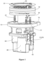
- Figure 1 is a structural schematic diagram of a lower electrode structure of an ion beam etching machine according to an embodiment of the present disclosure.
- Figure 2 is an exploded view of the lower electrode structure shown in Figure 1 .
- Figure 3 is a front view of the lower electrode structure shown in Figure 1 .
- the ion beam etching machine includes a vacuum chamber for etching and a lower electrode structure disposed in the vacuum chamber.
- the lower electrode structure is improved in the embodiment of the present disclosure.
- the lower electrode structure is explained in detail below.
- the lower electrode structure of the ion beam etching machine includes a pressing ring mechanism 10, a lifting mechanism 20 and an electrode plate 30.
- the pressing ring mechanism 10 is configured to support a to-be-etched component, such as a wafer 90.
- the lifting mechanism 20 is configured to drive the pressing ring mechanism 10 to rise and descend relative to the electrode plate 30, to place the to-be-etched component, such as the wafer 90, on the electrode plate 30 to facilitate subsequent etching operations.
- the wafer 90 is configured to represent a to-be-etched component. In actual applications, the to-be-etched component may also be other component as needed.
- the lifting mechanism 20 first drives the pressing ring mechanism 10 to rise relative to the electrode plate 30. That is, the pressing ring mechanism 10 moves upward in a direction away from the electrode plate 30.
- the wafer 90 transferred may be placed on the supporting structure of the pressing ring mechanism 10 by a robot or other equipment. Then the lifting mechanism 20 drives the pressing ring mechanism 10 to descend relative to the electrode plate 30 to place and press tightly the wafer 90 on the electrode plate 30.
- the lower electrode structure includes a partition 70, and the electrode plate 30 and the pressing ring mechanism 10 are disposed above the partition 70.
- the partition 70 is configured to separate a vacuum region and an atmosphere region in the main body of the lower electrode structure.
- the electrode plate 30 is a platform on which the wafer 90 is placed during the etching process. During the etching process, the electrode plate 30 may rotate around its axis, driving the wafer 90 to rotate together to improve the uniformity of etching.
- the lower electrode structure further includes a rotating mechanism 80 for driving the electrode plate 30 to rotate.
- the lifting mechanism 20 includes a lifting driving source 21 and a first bellows 22.
- the lifting driving source 21 may be a cylinder or a linear motor.
- the lifting driving source 21 is disposed below the partition 70.
- a movable end of the lifting driving source 21 is connected to the first bellows 22 to drive the first bellows 22 to rise and descend relative to the electrode plate 30.
- the first bellows 22 is disposed above the partition 70.
- An upper end of the first bellows 22 is connected to the pressing ring mechanism 10 through fasteners such as screws.
- the lifting driving source 21 drives the pressing ring mechanism 10 to rise and descend through the first bellows 22.
- first bellows 22 may be two or more according to actual needs, to facilitate arrangement.
- Each first bellows 22 may be provided with a corresponding driving source such as a cylinder. These first bellows 22 need to move synchronously.
- first bellows 22 may also be replaced by other components with elastic expansion and contraction functions.
- the lower electrode structure includes a position detection mechanism 40.
- the position detection mechanism 40 is configured to detect the position to which the pressing ring mechanism 10 descending relative to the electrode plate 30.
- the lifting mechanism 20 may also stop driving the pressing ring mechanism 10 to descend based on the detection information fed back by the position detection mechanism 40.
- a setting position where the wafer 90 is placed on the electrode plate 30 and the pressing ring mechanism 10 may fit the electrode plate 30 to press the wafer 90, may be determined based on a relative position arrangement of the pressing ring mechanism 10 and the electrode plate 30.
- the position detection mechanism 40 may detect whether the pressing ring mechanism 10 descends to the setting position. In a case that the pressing ring mechanism 10 descends to the setting position, the position detection mechanism 40 may feedback the corresponding information.
- the lifting mechanism 20 stops driving based on the feedback information to prevent the pressing ring mechanism 10 from continuing to descend and crushing the wafer 90.
- the position, to which the pressing ring mechanism 10 driven by the lifting mechanism 20 to descend may be accurately detected to prevent the wafer 90 from being crushed, which may improve the product yield and save costs.
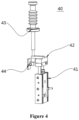
- Figure 4 is a schematic structural diagram of the position detection mechanism of the lower electrode structure in a specific embodiment.
- the position detection mechanism 40 includes an elastic member and a sensor 44.
- the elastic member may be compressed and deformed in a lifting direction of the pressing ring mechanism 10.
- the elastic member is disposed below the pressing ring mechanism 10.
- the pressing ring mechanism 10 may press the elastic member in a case of descending relative to the electrode plate 30.
- the sensor 44 is configured to detect a deformation amount of the elastic member.
- the elastic member is in the form of a bellows.
- the elastic member here is called a second bellows 43.
- the second bellows 43 of the position detection mechanism 40 is also disposed above the partition 70.
- the pressing ring mechanism 10 When the pressing ring mechanism 10 descends under the driving of the lifting mechanism 20, the pressing ring mechanism 10 may press the second bellows 43.
- the second bellows 43 is pressed to move downward.
- the sensor 44 may be configured to detect a position of the second bellows 43 to determine the position to which the pressing ring mechanism 10 descending.
- a position state of the pressing ring mechanism 10, when the pressing ring mechanism 10 first contacts the second bellows 43, may be determined in advance during descending of the pressing ring mechanism 10. Based on the position state, it is determined that how far the pressing ring mechanism 10 continues to descend to meet requirements for placing and pressing the wafer 90.
- the sensor 44 may feedback the detection information accordingly to determine whether the pressing ring mechanism 10 has dropped to a proper position.
- the position detection mechanism 40 may also include a driving part 41.
- the driving part 41 is configured to drive the second bellows 43 to rise and descend relative to the electrode plate 30, to adjust an initial relative position between the second bellows 43 and the pressing ring mechanism 10 to improve adaptability.
- the driving part 41 may be a cylinder or other driving structure.
- a telescopic end of the cylinder may be connected to a mounting base 42.
- the second bellows 43 and the sensor 44 are both mounted on the mounting base 42.
- the sensor 44 may be a photoelectric sensor or other sensing element capable of detecting a position of the second bellows 43.
- the driving part 41 of the position detection mechanism 40 and the lifting driving source 21 of the lifting mechanism 20 may be installed on the support frame 60 below the partition 70.
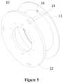
- Figure 5 is a schematic structural diagram of the pressing ring mechanism of the lower electrode structure in a specific embodiment.
- the pressing ring mechanism 10 includes a pressure ring 11, a weight plate 12 and a push rod 13.
- the pressure ring 11 and the weight plate 12 are connected through the push rod 13.
- the pressure ring 11 and the weight plate 12 can be connected by three push rods 13 to ensure the stability of the pressing ring mechanism 10.
- the three push rods 13 are evenly distributed in a circumferential direction of the pressure ring 11 to ensure the balance of the force during the lifting process.
- the number and arrangement of the push rods 13 may be set according to actual needs.
- the push rods 13 of the pressing ring mechanism 10 are configured to pass through the electrode plate 30.
- the pressure ring 11 of the pressing ring mechanism 10 is disposed above the electrode plate 30.
- the weight plate 12 is disposed below the electrode plate 30.
- the pressing ring 11 is provided with a supporting structure for supporting the wafer 90.
- the supporting structure for supporting the wafer 90 includes a support ring 14.
- the support ring 14 is fixed to a bottom surface of the pressure ring 11 facing the electrode plate 30.
- the support ring 14 has a spaced distance with the bottom surface of the electrode plate 30.
- the support ring 14 is provided with a supporting surface facing the pressure ring 11, that is, an upward supporting surface.
- the wafer 90 is supported by the supporting surface of the support ring 14, which can be understood with reference to Figure 3 .
- the wafer 90 may be placed on the electrode plate 30.
- a groove is further provided at a position of the electrode plate 30 corresponding to the support ring 14, to avoid interference between the support ring 14 and the electrode plate 30.
- the support ring 14 may be embedded in the groove after being descended to ensure that the wafer 90 is placed on the electrode plate.
- three support rings 14 may be evenly arranged in the circumferential direction of the pressure ring 11, to ensure the stability of supporting the wafer 90 and the reliability of driving the wafer 90 to rise and descend.
- other numbers and arrangements may also be used.
- the support ring 14 may be fixed to the pressure ring 11 through fasteners such as screws.
- the pressing ring mechanism 10 may rise and descend relative to the electrode plate 30. That is, the push rods 13 of the pressing ring mechanism 10 are in sliding fit with the electrode plate 30.
- the lower electrode structure further includes a guide mechanism 50, to ensure the accuracy of the rising and descending of the pressing ring mechanism 10.
- the guide mechanism 50 is configured to guide the rising and descending of the pressing ring mechanism 10 to prevent the pressing ring mechanism 10 from shifting during the lifting process. The product reliability is improved.
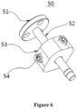
- Figure 6 is a schematic structural diagram of the guide mechanism in a specific embodiment.
- Figure 7 is a schematic cross-sectional view of the guide mechanism at the position of the plunger base in Figure 6 .
- the guide mechanism 50 includes a fixed base 51 and a guide shaft 52.
- the fixed base 51 is fixed to the bottom surface of the electrode plate 30.
- the guide shaft 52 is fixedly connected to the fixed base 51 and configured to pass through the weight plate 12.
- the axis direction of the guide shaft 52 is parallel to the lifting direction of the pressing ring mechanism 10. In this way, during the lifting process of the pressing ring mechanism 10, the weight plate 12 slides up and down along the guide shaft 52 to ensure the corresponding lifting direction of the electrode plate 30.
- the guide mechanism 50 further includes a plunger base 53 and a plunger 54 to further improve the reliability of the guide.
- the guide shaft 52 is also configured to pass through the plunger base 53.
- the plunger base 53 is disposed below the weight plate 12.
- the plunger 54 may move relative to the plunger base 53 to apply force to the guide shaft 52 in the radial direction of the guide shaft 52, to ensure that the position of the guide shaft 52 does not change.
- plungers 54 are provided.
- the four plungers 54 are connected to the plunger base 53 through threads along the radial direction of the guide shaft 52. In this way, the plunger 54 may be rotated to move in the radial direction of the guide shaft 52.
- the plunger 54 may be a spherical plunger. By rotating the four plungers 54, the guide shaft 52 can be clamped to ensure its guide position.
Landscapes
- Chemical & Material Sciences (AREA)
- Analytical Chemistry (AREA)
- Physics & Mathematics (AREA)
- Engineering & Computer Science (AREA)
- Plasma & Fusion (AREA)
- Drying Of Semiconductors (AREA)
Applications Claiming Priority (2)
| Application Number | Priority Date | Filing Date | Title |
|---|---|---|---|
| CN202111081752.1A CN115810530B (zh) | 2021-09-15 | 2021-09-15 | 离子束刻蚀机及其下电极结构 |
| PCT/CN2022/118026 WO2023040758A1 (zh) | 2021-09-15 | 2022-09-09 | 离子束刻蚀机及其下电极结构 |
Publications (2)
| Publication Number | Publication Date |
|---|---|
| EP4404236A1 true EP4404236A1 (de) | 2024-07-24 |
| EP4404236A4 EP4404236A4 (de) | 2025-10-08 |
Family
ID=85481902
Family Applications (1)
| Application Number | Title | Priority Date | Filing Date |
|---|---|---|---|
| EP22869127.5A Pending EP4404236A4 (de) | 2021-09-15 | 2022-09-09 | Ionenstrahlätzmaschine und unterelektrodenstruktur dafür |
Country Status (6)
| Country | Link |
|---|---|
| US (1) | US20250140512A1 (de) |
| EP (1) | EP4404236A4 (de) |
| KR (1) | KR102886201B1 (de) |
| CN (1) | CN115810530B (de) |
| TW (1) | TWI837823B (de) |
| WO (1) | WO2023040758A1 (de) |
Families Citing this family (3)
| Publication number | Priority date | Publication date | Assignee | Title |
|---|---|---|---|---|
| CN116525399A (zh) * | 2023-05-19 | 2023-08-01 | 中国科学院自动化研究所 | 离子束刻蚀电极装置 |
| CN117116734B (zh) * | 2023-09-04 | 2024-03-19 | 珠海恒格微电子装备有限公司 | 一种用于刻蚀腔的封闭式控制装置及其刻蚀机 |
| CN118588529B (zh) * | 2024-08-06 | 2024-11-15 | 苏州佑伦真空设备科技有限公司 | 一种ibe离子束刻蚀装置 |
Family Cites Families (10)
| Publication number | Priority date | Publication date | Assignee | Title |
|---|---|---|---|---|
| KR200195099Y1 (ko) * | 1997-12-16 | 2000-09-01 | 김영환 | 반도체 웨이퍼용 클램핑장치 |
| JP2000077392A (ja) * | 1998-09-01 | 2000-03-14 | Matsushita Electric Ind Co Ltd | 真空処理装置 |
| US20040066601A1 (en) * | 2002-10-04 | 2004-04-08 | Varian Semiconductor Equipment Associates, Inc. | Electrode configuration for retaining cooling gas on electrostatic wafer clamp |
| KR20080092766A (ko) * | 2007-04-13 | 2008-10-16 | (주)소슬 | 기판 지지대 및 이를 구비하는 플라즈마 처리 장치 |
| CN103367215B (zh) * | 2013-06-08 | 2016-08-24 | 天通吉成机器技术有限公司 | 一种等离子刻蚀设备的基片定位升降装置 |
| CN105390430B (zh) * | 2014-09-09 | 2018-08-24 | 北京北方华创微电子装备有限公司 | 一种压环压紧机构 |
| CN105609459B (zh) * | 2014-11-14 | 2020-01-03 | 北京北方华创微电子装备有限公司 | 基片固定方法及装置、半导体加工设备 |
| CN107611054B (zh) * | 2016-07-12 | 2020-02-14 | 北京北方华创微电子装备有限公司 | 反应腔室 |
| US10460916B2 (en) * | 2017-05-15 | 2019-10-29 | Applied Materials, Inc. | Real time monitoring with closed loop chucking force control |
| CN111341720A (zh) * | 2018-12-19 | 2020-06-26 | 江苏鲁汶仪器有限公司 | 一种晶圆卸载和压紧装置 |
-
2021
- 2021-09-15 CN CN202111081752.1A patent/CN115810530B/zh active Active
-
2022
- 2022-09-09 US US18/681,776 patent/US20250140512A1/en active Pending
- 2022-09-09 EP EP22869127.5A patent/EP4404236A4/de active Pending
- 2022-09-09 WO PCT/CN2022/118026 patent/WO2023040758A1/zh not_active Ceased
- 2022-09-09 KR KR1020247004459A patent/KR102886201B1/ko active Active
- 2022-09-13 TW TW111134594A patent/TWI837823B/zh active
Also Published As
| Publication number | Publication date |
|---|---|
| TWI837823B (zh) | 2024-04-01 |
| CN115810530B (zh) | 2025-02-14 |
| CN115810530A (zh) | 2023-03-17 |
| KR20240031387A (ko) | 2024-03-07 |
| KR102886201B1 (ko) | 2025-11-13 |
| EP4404236A4 (de) | 2025-10-08 |
| TW202314763A (zh) | 2023-04-01 |
| WO2023040758A1 (zh) | 2023-03-23 |
| US20250140512A1 (en) | 2025-05-01 |
Similar Documents
| Publication | Publication Date | Title |
|---|---|---|
| EP4404236A1 (de) | Ionenstrahlätzmaschine und unterelektrodenstruktur dafür | |
| KR102642283B1 (ko) | 운반 장치 및 반도체 반응 챔버 | |
| KR102197957B1 (ko) | 모터 전단커버 단면 런아웃 측정장치 | |
| CN111426972B (zh) | 一种多通道阻差均衡及聚能快固一体机 | |
| CN109270285B (zh) | 一种真空进样装置 | |
| CN112952175A (zh) | 用于压装燃料电池堆的压装机及压装方法 | |
| CN118100546A (zh) | 一种永磁伺服电机定转子合装与分离装置 | |
| CN115597444B (zh) | 一种配重加压机构、含能粉体材料压装装置及压装设备 | |
| CN212113618U (zh) | 上电极提升装置及半导体设备 | |
| WO2023068844A1 (ko) | 용접 압력 제어 시스템, 이를 이용하는 용접 압력 제어 방법 및 이를 이용하는 용접대상물 두께 측정방법 | |
| CN113804279B (zh) | 一种输送链上的称重装置及其工作方法 | |
| CN213398658U (zh) | 用于面板的对准装置 | |
| CN108195335B (zh) | 一种电机轴向间隙自动检测和修正设备 | |
| CN100517631C (zh) | 举升装置及调整举升装置平面度的方法 | |
| CN221090049U (zh) | 一种氢能电极板热压设备 | |
| CN210617118U (zh) | 一种金属件的注塑机自动上料装置 | |
| CN218539799U (zh) | 一种真空腔体用升降结构及系统 | |
| CN217444366U (zh) | 一种晶圆载台装置及晶圆压紧机构 | |
| CN112952174A (zh) | 用于压装燃料电池堆的压装机及压装组件 | |
| CN217114355U (zh) | 一种晶圆对准装置及安装结构 | |
| CN115451030A (zh) | 一种滚针轴承装配结构 | |
| CN112687568A (zh) | 半导体工艺设备及其承载装置 | |
| CN115896738A (zh) | 环形屏蔽件及薄膜沉积设备 | |
| CN216980529U (zh) | 晶圆压紧装置 | |
| CN117450979B (zh) | 一种中大型深沟球轴承径向游隙检测机构 |
Legal Events
| Date | Code | Title | Description |
|---|---|---|---|
| STAA | Information on the status of an ep patent application or granted ep patent |
Free format text: STATUS: THE INTERNATIONAL PUBLICATION HAS BEEN MADE |
|
| PUAI | Public reference made under article 153(3) epc to a published international application that has entered the european phase |
Free format text: ORIGINAL CODE: 0009012 |
|
| STAA | Information on the status of an ep patent application or granted ep patent |
Free format text: STATUS: REQUEST FOR EXAMINATION WAS MADE |
|
| 17P | Request for examination filed |
Effective date: 20240415 |
|
| AK | Designated contracting states |
Kind code of ref document: A1 Designated state(s): AL AT BE BG CH CY CZ DE DK EE ES FI FR GB GR HR HU IE IS IT LI LT LU LV MC MK MT NL NO PL PT RO RS SE SI SK SM TR |
|
| DAV | Request for validation of the european patent (deleted) | ||
| DAX | Request for extension of the european patent (deleted) | ||
| A4 | Supplementary search report drawn up and despatched |
Effective date: 20250910 |
|
| RIC1 | Information provided on ipc code assigned before grant |
Ipc: H01J 37/305 20060101AFI20250904BHEP Ipc: H01J 37/32 20060101ALI20250904BHEP Ipc: H01L 21/687 20060101ALI20250904BHEP |