EP4404218A1 - Power cable with non-metallic tape armour - Google Patents
Power cable with non-metallic tape armour Download PDFInfo
- Publication number
- EP4404218A1 EP4404218A1 EP24152413.1A EP24152413A EP4404218A1 EP 4404218 A1 EP4404218 A1 EP 4404218A1 EP 24152413 A EP24152413 A EP 24152413A EP 4404218 A1 EP4404218 A1 EP 4404218A1
- Authority
- EP
- European Patent Office
- Prior art keywords
- power cable
- meshed
- tape
- cable
- armour
- Prior art date
- Legal status (The legal status is an assumption and is not a legal conclusion. Google has not performed a legal analysis and makes no representation as to the accuracy of the status listed.)
- Pending
Links
- 239000004020 conductor Substances 0.000 claims abstract description 19
- 239000003292 glue Substances 0.000 claims description 9
- 239000000463 material Substances 0.000 claims description 7
- 239000007769 metal material Substances 0.000 claims description 7
- 239000011248 coating agent Substances 0.000 claims description 5
- 238000000576 coating method Methods 0.000 claims description 5
- 239000005445 natural material Substances 0.000 claims description 2
- 239000002861 polymer material Substances 0.000 claims description 2
- 239000010410 layer Substances 0.000 description 45
- 238000004519 manufacturing process Methods 0.000 description 9
- 239000002184 metal Substances 0.000 description 9
- 229910052751 metal Inorganic materials 0.000 description 9
- RYGMFSIKBFXOCR-UHFFFAOYSA-N Copper Chemical compound [Cu] RYGMFSIKBFXOCR-UHFFFAOYSA-N 0.000 description 6
- 239000012790 adhesive layer Substances 0.000 description 5
- 238000009413 insulation Methods 0.000 description 5
- -1 polypropylene Polymers 0.000 description 5
- 238000004804 winding Methods 0.000 description 5
- 230000017525 heat dissipation Effects 0.000 description 4
- 239000000203 mixture Substances 0.000 description 4
- 239000004743 Polypropylene Substances 0.000 description 3
- 229910000831 Steel Inorganic materials 0.000 description 3
- 239000004744 fabric Substances 0.000 description 3
- 239000000945 filler Substances 0.000 description 3
- 239000012943 hotmelt Substances 0.000 description 3
- 229920001155 polypropylene Polymers 0.000 description 3
- 239000010959 steel Substances 0.000 description 3
- 239000004698 Polyethylene Substances 0.000 description 2
- 229920006226 ethylene-acrylic acid Polymers 0.000 description 2
- 239000011152 fibreglass Substances 0.000 description 2
- 239000011810 insulating material Substances 0.000 description 2
- 229920000728 polyester Polymers 0.000 description 2
- 229920000573 polyethylene Polymers 0.000 description 2
- 229920000642 polymer Polymers 0.000 description 2
- XLYOFNOQVPJJNP-UHFFFAOYSA-N water Substances O XLYOFNOQVPJJNP-UHFFFAOYSA-N 0.000 description 2
- OKTJSMMVPCPJKN-UHFFFAOYSA-N Carbon Chemical compound [C] OKTJSMMVPCPJKN-UHFFFAOYSA-N 0.000 description 1
- 229920012266 Poly(ether sulfone) PES Polymers 0.000 description 1
- 239000004952 Polyamide Substances 0.000 description 1
- 238000005299 abrasion Methods 0.000 description 1
- 238000009954 braiding Methods 0.000 description 1
- 229910052799 carbon Inorganic materials 0.000 description 1
- 229910052802 copper Inorganic materials 0.000 description 1
- 239000010949 copper Substances 0.000 description 1
- 239000003822 epoxy resin Substances 0.000 description 1
- QHZOMAXECYYXGP-UHFFFAOYSA-N ethene;prop-2-enoic acid Chemical group C=C.OC(=O)C=C QHZOMAXECYYXGP-UHFFFAOYSA-N 0.000 description 1
- 238000001125 extrusion Methods 0.000 description 1
- 230000005294 ferromagnetic effect Effects 0.000 description 1
- 239000000835 fiber Substances 0.000 description 1
- 239000011521 glass Substances 0.000 description 1
- 238000009434 installation Methods 0.000 description 1
- 150000002739 metals Chemical class 0.000 description 1
- 238000000034 method Methods 0.000 description 1
- 239000013307 optical fiber Substances 0.000 description 1
- 238000013021 overheating Methods 0.000 description 1
- 229920002647 polyamide Polymers 0.000 description 1
- 229920000647 polyepoxide Polymers 0.000 description 1
- 239000004800 polyvinyl chloride Substances 0.000 description 1
- 230000001681 protective effect Effects 0.000 description 1
- 229920005989 resin Polymers 0.000 description 1
- 239000011347 resin Substances 0.000 description 1
- 239000002356 single layer Substances 0.000 description 1
- 238000009941 weaving Methods 0.000 description 1
Images

Classifications
-
- H—ELECTRICITY
- H01—ELECTRIC ELEMENTS
- H01B—CABLES; CONDUCTORS; INSULATORS; SELECTION OF MATERIALS FOR THEIR CONDUCTIVE, INSULATING OR DIELECTRIC PROPERTIES
- H01B7/00—Insulated conductors or cables characterised by their form
- H01B7/14—Submarine cables
-
- H—ELECTRICITY
- H01—ELECTRIC ELEMENTS
- H01B—CABLES; CONDUCTORS; INSULATORS; SELECTION OF MATERIALS FOR THEIR CONDUCTIVE, INSULATING OR DIELECTRIC PROPERTIES
- H01B7/00—Insulated conductors or cables characterised by their form
- H01B7/17—Protection against damage caused by external factors, e.g. sheaths or armouring
- H01B7/18—Protection against damage caused by wear, mechanical force or pressure; Sheaths; Armouring
- H01B7/182—Protection against damage caused by wear, mechanical force or pressure; Sheaths; Armouring comprising synthetic filaments
-
- H—ELECTRICITY
- H01—ELECTRIC ELEMENTS
- H01B—CABLES; CONDUCTORS; INSULATORS; SELECTION OF MATERIALS FOR THEIR CONDUCTIVE, INSULATING OR DIELECTRIC PROPERTIES
- H01B7/00—Insulated conductors or cables characterised by their form
- H01B7/02—Disposition of insulation
- H01B7/0208—Cables with several layers of insulating material
- H01B7/0225—Three or more layers
-
- H—ELECTRICITY
- H01—ELECTRIC ELEMENTS
- H01B—CABLES; CONDUCTORS; INSULATORS; SELECTION OF MATERIALS FOR THEIR CONDUCTIVE, INSULATING OR DIELECTRIC PROPERTIES
- H01B7/00—Insulated conductors or cables characterised by their form
- H01B7/02—Disposition of insulation
- H01B7/0275—Disposition of insulation comprising one or more extruded layers of insulation
- H01B7/0283—Disposition of insulation comprising one or more extruded layers of insulation comprising in addition one or more other layers of non-extruded insulation
-
- H—ELECTRICITY
- H01—ELECTRIC ELEMENTS
- H01B—CABLES; CONDUCTORS; INSULATORS; SELECTION OF MATERIALS FOR THEIR CONDUCTIVE, INSULATING OR DIELECTRIC PROPERTIES
- H01B7/00—Insulated conductors or cables characterised by their form
- H01B7/17—Protection against damage caused by external factors, e.g. sheaths or armouring
- H01B7/18—Protection against damage caused by wear, mechanical force or pressure; Sheaths; Armouring
- H01B7/182—Protection against damage caused by wear, mechanical force or pressure; Sheaths; Armouring comprising synthetic filaments
- H01B7/183—Protection against damage caused by wear, mechanical force or pressure; Sheaths; Armouring comprising synthetic filaments forming part of an outer sheath
-
- H—ELECTRICITY
- H01—ELECTRIC ELEMENTS
- H01B—CABLES; CONDUCTORS; INSULATORS; SELECTION OF MATERIALS FOR THEIR CONDUCTIVE, INSULATING OR DIELECTRIC PROPERTIES
- H01B7/00—Insulated conductors or cables characterised by their form
- H01B7/17—Protection against damage caused by external factors, e.g. sheaths or armouring
- H01B7/18—Protection against damage caused by wear, mechanical force or pressure; Sheaths; Armouring
- H01B7/1855—Sheaths comprising helical wrapped non-metallic layers
-
- H—ELECTRICITY
- H01—ELECTRIC ELEMENTS
- H01B—CABLES; CONDUCTORS; INSULATORS; SELECTION OF MATERIALS FOR THEIR CONDUCTIVE, INSULATING OR DIELECTRIC PROPERTIES
- H01B7/00—Insulated conductors or cables characterised by their form
- H01B7/17—Protection against damage caused by external factors, e.g. sheaths or armouring
- H01B7/18—Protection against damage caused by wear, mechanical force or pressure; Sheaths; Armouring
- H01B7/1865—Sheaths comprising braided non-metallic layers
-
- H—ELECTRICITY
- H01—ELECTRIC ELEMENTS
- H01B—CABLES; CONDUCTORS; INSULATORS; SELECTION OF MATERIALS FOR THEIR CONDUCTIVE, INSULATING OR DIELECTRIC PROPERTIES
- H01B7/00—Insulated conductors or cables characterised by their form
- H01B7/17—Protection against damage caused by external factors, e.g. sheaths or armouring
- H01B7/18—Protection against damage caused by wear, mechanical force or pressure; Sheaths; Armouring
- H01B7/1875—Multi-layer sheaths
- H01B7/188—Inter-layer adherence promoting means
-
- H—ELECTRICITY
- H01—ELECTRIC ELEMENTS
- H01B—CABLES; CONDUCTORS; INSULATORS; SELECTION OF MATERIALS FOR THEIR CONDUCTIVE, INSULATING OR DIELECTRIC PROPERTIES
- H01B7/00—Insulated conductors or cables characterised by their form
- H01B7/17—Protection against damage caused by external factors, e.g. sheaths or armouring
- H01B7/18—Protection against damage caused by wear, mechanical force or pressure; Sheaths; Armouring
- H01B7/1895—Internal space filling-up means
-
- H—ELECTRICITY
- H01—ELECTRIC ELEMENTS
- H01B—CABLES; CONDUCTORS; INSULATORS; SELECTION OF MATERIALS FOR THEIR CONDUCTIVE, INSULATING OR DIELECTRIC PROPERTIES
- H01B7/00—Insulated conductors or cables characterised by their form
- H01B7/42—Insulated conductors or cables characterised by their form with arrangements for heat dissipation or conduction
- H01B7/421—Insulated conductors or cables characterised by their form with arrangements for heat dissipation or conduction for heat dissipation
-
- H—ELECTRICITY
- H01—ELECTRIC ELEMENTS
- H01B—CABLES; CONDUCTORS; INSULATORS; SELECTION OF MATERIALS FOR THEIR CONDUCTIVE, INSULATING OR DIELECTRIC PROPERTIES
- H01B9/00—Power cables
- H01B9/02—Power cables with screens or conductive layers, e.g. for avoiding large potential gradients
-
- H—ELECTRICITY
- H01—ELECTRIC ELEMENTS
- H01B—CABLES; CONDUCTORS; INSULATORS; SELECTION OF MATERIALS FOR THEIR CONDUCTIVE, INSULATING OR DIELECTRIC PROPERTIES
- H01B7/00—Insulated conductors or cables characterised by their form
- H01B7/17—Protection against damage caused by external factors, e.g. sheaths or armouring
- H01B7/18—Protection against damage caused by wear, mechanical force or pressure; Sheaths; Armouring
- H01B7/22—Metal wires or tapes, e.g. made of steel
- H01B7/228—Metal braid
-
- H—ELECTRICITY
- H01—ELECTRIC ELEMENTS
- H01B—CABLES; CONDUCTORS; INSULATORS; SELECTION OF MATERIALS FOR THEIR CONDUCTIVE, INSULATING OR DIELECTRIC PROPERTIES
- H01B9/00—Power cables
- H01B9/02—Power cables with screens or conductive layers, e.g. for avoiding large potential gradients
- H01B9/027—Power cables with screens or conductive layers, e.g. for avoiding large potential gradients composed of semi-conducting layers
Definitions
- the present disclosure refers to a power cable with non-metallic tape armour particularly but not exclusively suitable for underwater deployment.
- AC alternate current
- power cables for underwater deployment at low depth, e.g. lower than 500 m, but all the following considerations can be applied also to any type of power cable.
- a power cable typically includes at least one cable core usually formed by an electrically conductive metal conductor covered by an insulation system.
- the insulation system can be sequentially formed by an inner polymeric semiconductive layer, an intermediate polymeric insulating layer, and an outer polymeric semiconductive layer.
- the insulation system is usually then surrounded by a metallic screen generally made of lead and/or copper and, optionally by a semiconductive sheath.
- a bedding layer for example made of wound polymeric yarns or tapes, may surround the at least one core.
- the power cable may also comprise a filler material or shaped filling elements between the cores that are together surrounded by the bedding layer.
- the bedding layer is then surrounded by an armour which is designed in view of the intended application and which can be surrounded by a serving layer.
- the armour in case of deployment at low depth (like 200 m) can be made of a single layer of steel wires surrounded by bituminous polypropylene yarns as a serving layer in order to avoid abrasion.
- the main aim of the armour is to provide protection against lateral stress, i.e. against impact and crushing.
- metallic armours besides being a heavy portion of the cable, can be a source of power loss in AC cables. This could be avoided by using amagnetic metals but these are generally quite more expensive.
- the armour can be made of a mixture of ferromagnetic or, better, amagnetic metal wires and dielectric wires, e.g. fiberglass coated polyethylene wires: such a mixed armour is less expensive than that made of amagnetic metal only, but also less performing in terms of meshed tape tear resistance and of heat dissipation as the dielectric wires generally have a thermal conductivity lower than the metallic wires.
- An armour can be be made of solely dielectric wires, for example in form of fiberglass coated polyethylene wires having a round cross-section. This kind of armour is even more economic and light, but the above mentioned problems of low meshed tape tear resistance and thermal conductivity increase.
- Another problem relates to the manufacturing of a wire armoured cable, especially for "big" cable, for example cables for a voltage greater than or equal to 220 kV and/or with conductors having each a cross-section greater than or equal to 1000 mm2.
- each bobbin contains 3 km of one armour wire and when an armoured cable 20 km-long and with an armour layer made of 110 wires is to be produced, the manufacturing lines should be stopped from about 50 up to about 100 times every 3 km to replace the empty bobbin and jointing the wires. This clearly reduces the productivity and increases the cost.
- GB836660 relates to electric cables for telecommunication purposes, for underground, aerial or submarine installation.
- various proposals have been made for reducing the amount of steel wire and using strong insulating materials which in addition to their electrical function also take part of the function of the armour.
- the use of polypropylene as insulating material for the conductors and as a protective covering so that it can take the mechanical stresses, is highly successful owing to its remarkable characteristics of mechanical strength and its extreme lightness. It enables the steel wire armour to be eliminated entirely in many cases.
- the cable for telecommunications comprises two or more conductors insulated by an insulating composition consisting at least predominantly of a linear, highly crystalline, polypropylene in the form of a sheath formed by extrusion or applying it in the form of ropes or tapes.
- US7555182 relates to an armor laminate for use with a variety of different cable structures.
- the armor wrap has at least one water absorbing fabric layer, at least one polymer layer, and at least one layer fabricated from a metal.
- the water absorbing fabric can comprise a carded polyester non-woven material.
- the polymer layer is ethylene acrylic acid (EAA) or a coextruded blend thereof.
- US20160358693 relates to a method for manufacturing a cable.
- An armor layer is provided between the inner protection jacket layer and the outer protection jacket layer, and the armor layer is formed by lap wrapping a double-layer metal tape along an identical direction with a gap.
- WO2022067934 relates to a special degaussing cable for a fixed winding for an underwater vehicle comprising, inter alia, an armour layer which can be made of two layers of tinned copper wire net.
- the armoring layer is woven from two layers of tinned copper wire mesh with the same specification, the specification of the tinned copper wire mesh is 40/in, the two layers of copper wire mesh are staggered, and the weaving angle is 40 ⁇ 60°, the braiding coverage rate is 88%-92%, the diameter of the single wire of the copper core is 0.2-0.4mm, and it is twisted into strands with a pitch ratio of 8 to 10 times, and the strands are twisted in the opposite direction to the original bundle.
- the Applicant faced the problem of providing a power cable, particularly for submarine applications, with an armour simple to be manufactured and at the same time capable of assuring protection against lateral stress, good heat dissipation and low power losses.
- a metal tape still gives problems of power loss and could not provide the sought protection against side stress.
- An amagnetic metal tape reduces the power loss problem, but not that of the lateral protection, besides being more expensive.
- the Applicant has thought to make the armour with a tape of non-metallic material, in particular, a non-metallic material capable of assuring the protection against lateral stress.
- a non-metallic material generally has a thermal conductivity lower than that of a metal, and an armour in form of a tape of non-metallic material could give rise to overheating problems.
- a non-metallic armour in form of a meshed tape with an openness factor of at least 30% and a meshed tape tear resistance of at least 200 N assures a good heat dissipation and suitable protection against lateral stress.
- openness factor it is intended the percentage of perforation in a surface unit. Higher openness percentages indicate a looser fabric weave.
- the present disclosure relates to a power cable comprising:
- the power cable of the present disclosure can carry either alternate current or direct current.
- the cable of the present disclosure have three insulated conductors twisted one another along the cable longitudinal direction.
- the at least one meshed tape of the present disclosure has a thickness of from 0.5 to 2.5 mm.
- the non-metallic armour allows easing the cable manufacturing and increasing the speed thereof.
- the tape can be stored in pads that are simpler and quicker to be changed with respect to bobbins.
- the number of pads is certainly smaller than the number of bobbins since the tape, typically wider than 10 mm, can cover a surface of the power cable far greater than than of a wire (typically having a diameter of 6-8 mm). The manufacturing results to be simpler, faster and cheaper with respect to the wire armours.
- the manufacturing lines has to be stopped about 30 times to replace the empty pad and jointing the tapes, thus much less times with respect to the wire armoured cable.
- the overall diameter of the finished power cable results to be lower with respect to that of a wire armoured cable of the same voltage class, since the thicknes of the tape is smaller than the diameter of the wire used for the armours. And it is apparent that also the cable weight is reduced.
- the non-metallic armour comprises at least two meshed tapes wherein a first meshed tape surrounds the bedding layer and a second meshed tape surrounds the first meshed tape.
- non-metallic armour is made of weft yarns and warp yarns interwoven to each other.
- the weft yarns and the warp yarns can be made of a polymeric material such as polyester or polyethersulfone (PES), or of an inorganic and non-metallic material such as glass or carbon fibre, or of a natural material; or of a mixture thereof.
- a polymeric material such as polyester or polyethersulfone (PES)
- PES polyethersulfone
- an inorganic and non-metallic material such as glass or carbon fibre, or of a natural material; or of a mixture thereof.
- weft yarns and warp yarns of the meshed tape of the disclosure are coated with a coating.
- the coating is made of a polymer material such as polyvinylchloride (PVC) or a polyamide; or of a resin such as an epoxy resin.
- PVC polyvinylchloride
- a resin such as an epoxy resin.
- the at least one meshed tape has an outer surface and an inner surface wherein the outer surface is at least partially coated with a glue.
- the non-metallic armour comprises at least two meshed tapes
- the presence of a glue on the outer surface improves the overall stability of the non-metallic armour.
- the inner surface of at least one meshed tape is at least partially coated with a glue. In this way the adhesion between the meshed tape and the bedding layer is more stable.
- the non-metallic armour comprises at least two meshed tapes, the presence of a glue on the inner surface improves the overall stability of the non-metallic armour.
- insulation layer it is meant a layer made of a material having a conductivity comprised between 10 -16 and 10 -14 S/m.
- semiconductor layer it is meant a layer made of a material having a conductivity comprised between 10 -1 and 10 S/m.
- the power cable 100 comprises three insulated conductors 110 twisted one another along a longitudinal direction (A).
- Each insulated conductor 110 comprises one electric conductor 115 surrounded by a polymeric insulation system 200.
- Each polymeric insulation system 200 is sequentially formed by an inner polymeric semiconductive layer 210, a polymeric insulating layer 220, and an outer polymeric semiconductive layer 230.
- Each insulated conductor 100 may comprise also a metallic screen 240 arranged in a radially outer position with respect to the outer polymeric semiconductive layer 230.
- a semiconductive sheath 250 may be arranged in a radially outer position with respect to the metallic screen 240 like in the embodiment of Figure 1 .
- the three insulated conductors 110 may be twisted to each other forming a cable core and a bedding layer 260 surrounds the three insulated conductors 110.
- the power cable 100 also may comprise a filler (not illustrated) placed inside the space between the cable core and the bedding layer 260.
- the filler in particular, may be made of an extruded polymeric material or of polymeric filaments, or may be in form of three shaped elements each defining a plurality of spaces that can be used as seats for optical fiber cables (not illustrated).
- a non-metallic armour 120 surrounds the bedding layer 260.
- the non-metallic armour 120 is made by two meshed tapes 120', 120'' helically wound around the bedding layer 260.
- Each meshed tape has an openness factor of at least 30% and a meshed tape tear resistance warp/weft of at least 200 N.
- a higher limit of the openness factor for the meshed tape of the disclosure is the one corresponding to the minimum value of the meshed tape tear resistance warp/weft.
- Such higher limit value is the one corresponding to the minimum value of the openness factor.
- the non-metallic armour is made by two meshed tapes 120', 120'' wherein a first meshed tape 120' surrounds the bedding layer 260 according to a first winding direction and a second meshed tape 120" surrounds the first meshed tape 120' according to a second winding direction.
- the first winding direction may be opposite or may be substantially parallel to the second winding direction.
- a single meshed tape has a thickness of about 0.5 to 2.5 mm. Therefore, for example, in the embodiments with two meshed tapes the overall thickness is about 1 to 5 mm.
- the non-metallic armour 120 may be made of polymeric weft yarns and polymeric warp yarns interwoven to each other, optionally coated with a polymeric coating.
- the power cable 100 may comprise a serving layer 270 that surrounds the outer meshed tape like in the embodiment of Figure 1 .
- Each one of the meshed tapes 120', 120" has an outer surface and an inner surface and at least the outer surface of the second meshed tape 120'' is at least partially covered by an adhesive layer (not illustrated) made, for example, by hot-melt glue that results to be placed between the outer meshed tape 120" and the serving layer 270.
- the inner surface of at least the first meshed tape 120' is at least partially covered by an adhesive layer (not illustrated) made, for example, by hot-melt glue that results to be placed between the first meshed tape 120' and the bedding layer 270.
- the outer surface of the first meshed tape 120' and/or the inner surface of the second meshed tape 120" may be at least partially covered by an adhesive layer.
- the presence of an adhesive layer on the outer surface of the first meshed tape 120' and, at the same time, on the inner surface of the second meshed tape 120" could be redundant.
- a third adhesive layer (not illustrated) made for example by hot-melt glue between two consecutive meshed tape 120' 120" like in the embodiment of Figure 1 .
Landscapes
- Insulated Conductors (AREA)
Abstract
Power cable (100) comprising:
- at least one insulated conductor (110) extending along a cable longitudinal direction (A);
- a bedding layer (260) surrounding the at least one insulated conductor (110);
- a non-metallic armour (120) surrounding the bedding layer (260), the non-metallic armour (120) being made by at least one meshed tape (120', 120") helically wound onto the bedding layer (260), and having an openness factor of at least 30% and a meshed tape tear resistance of at least 200 N according to DIN 53363 of 2003.
- at least one insulated conductor (110) extending along a cable longitudinal direction (A);
- a bedding layer (260) surrounding the at least one insulated conductor (110);
- a non-metallic armour (120) surrounding the bedding layer (260), the non-metallic armour (120) being made by at least one meshed tape (120', 120") helically wound onto the bedding layer (260), and having an openness factor of at least 30% and a meshed tape tear resistance of at least 200 N according to DIN 53363 of 2003.
Description
- The present disclosure refers to a power cable with non-metallic tape armour particularly but not exclusively suitable for underwater deployment.
- In the present description reference will be made to AC (alternate current) power cables for underwater deployment at low depth, e.g. lower than 500 m, but all the following considerations can be applied also to any type of power cable.
- Typically, a power cable includes at least one cable core usually formed by an electrically conductive metal conductor covered by an insulation system. The insulation system can be sequentially formed by an inner polymeric semiconductive layer, an intermediate polymeric insulating layer, and an outer polymeric semiconductive layer. The insulation system is usually then surrounded by a metallic screen generally made of lead and/or copper and, optionally by a semiconductive sheath. A bedding layer, for example made of wound polymeric yarns or tapes, may surround the at least one core. When the power cable comprises more than one cable core, i.e. three cable cores, the power cable may also comprise a filler material or shaped filling elements between the cores that are together surrounded by the bedding layer.
- In any case the bedding layer is then surrounded by an armour which is designed in view of the intended application and which can be surrounded by a serving layer.
- For example, in case of deployment at low depth (like 200 m) the armour can be made of a single layer of steel wires surrounded by bituminous polypropylene yarns as a serving layer in order to avoid abrasion.
- In the case of low-depth cable, the main aim of the armour is to provide protection against lateral stress, i.e. against impact and crushing. However metallic armours, besides being a heavy portion of the cable, can be a source of power loss in AC cables. This could be avoided by using amagnetic metals but these are generally quite more expensive. As an alternative, the armour can be made of a mixture of ferromagnetic or, better, amagnetic metal wires and dielectric wires, e.g. fiberglass coated polyethylene wires: such a mixed armour is less expensive than that made of amagnetic metal only, but also less performing in terms of meshed tape tear resistance and of heat dissipation as the dielectric wires generally have a thermal conductivity lower than the metallic wires.
- An armour can be be made of solely dielectric wires, for example in form of fiberglass coated polyethylene wires having a round cross-section. This kind of armour is even more economic and light, but the above mentioned problems of low meshed tape tear resistance and thermal conductivity increase.
- Another problem relates to the manufacturing of a wire armoured cable, especially for "big" cable, for example cables for a voltage greater than or equal to 220 kV and/or with conductors having each a cross-section greater than or equal to 1000 mm2.
- Indeed for such big cables it is necessary to arrange one or more bobbin for each wire depending on the size of the cable. Depending on the size of the cable to be armoured, it could be necessary to stop the manufacturing line several times to replace the empty bobbin and jointing the wires.
- For example, when each bobbin contains 3 km of one armour wire and when an armoured cable 20 km-long and with an armour layer made of 110 wires is to be produced, the manufacturing lines should be stopped from about 50 up to about 100 times every 3 km to replace the empty bobbin and jointing the wires. This clearly reduces the productivity and increases the cost.
-
GB836660 US7555182 relates to an armor laminate for use with a variety of different cable structures. The armor wrap has at least one water absorbing fabric layer, at least one polymer layer, and at least one layer fabricated from a metal. The water absorbing fabric can comprise a carded polyester non-woven material. The polymer layer is ethylene acrylic acid (EAA) or a coextruded blend thereof. -
US20160358693 relates to a method for manufacturing a cable. An armor layer is provided between the inner protection jacket layer and the outer protection jacket layer, and the armor layer is formed by lap wrapping a double-layer metal tape along an identical direction with a gap. -
WO2022067934 relates to a special degaussing cable for a fixed winding for an underwater vehicle comprising, inter alia, an armour layer which can be made of two layers of tinned copper wire net. The armoring layer is woven from two layers of tinned copper wire mesh with the same specification, the specification of the tinned copper wire mesh is 40/in, the two layers of copper wire mesh are staggered, and the weaving angle is 40 ~ 60°, the braiding coverage rate is 88%-92%, the diameter of the single wire of the copper core is 0.2-0.4mm, and it is twisted into strands with a pitch ratio of 8 to 10 times, and the strands are twisted in the opposite direction to the original bundle. - The Applicant faced the problem of providing a power cable, particularly for submarine applications, with an armour simple to be manufactured and at the same time capable of assuring protection against lateral stress, good heat dissipation and low power losses.
- In order to simplify the manufacturing of the cable the Applicant considered to make an armour in form of tape instead of an armour made of a plurality of wires.
- But a metal tape still gives problems of power loss and could not provide the sought protection against side stress. An amagnetic metal tape reduces the power loss problem, but not that of the lateral protection, besides being more expensive.Thus the Applicant has thought to make the armour with a tape of non-metallic material, in particular, a non-metallic material capable of assuring the protection against lateral stress. However, a non-metallic material generally has a thermal conductivity lower than that of a metal, and an armour in form of a tape of non-metallic material could give rise to overheating problems.
- The Applicant experienced that a non-metallic armour in form of a meshed tape with an openness factor of at least 30% and a meshed tape tear resistance of at least 200 N assures a good heat dissipation and suitable protection against lateral stress.
- For openness factor it is intended the percentage of perforation in a surface unit. Higher openness percentages indicate a looser fabric weave.
- Therefore, according to a first aspect, the present disclosure relates to a power cable comprising:
- at least one insulated conductor extending along a cable longitudinal direction;
- a bedding layer surrounding the at least one insulated conductor;
- a non-metallic armour surrounding the bedding layer, the non-metallic armour being made by at least one meshed tape helically wound onto the bedding layer, and having an openness factor of at least 30% and a meshed tape tear resistance warp/weft of at least 200 N according to DIN 53363 of 2003.
- The power cable of the present disclosure can carry either alternate current or direct current.
- In an embodiment, the cable of the present disclosure have three insulated conductors twisted one another along the cable longitudinal direction.
- In an embodiment, the at least one meshed tape of the present disclosure has a thickness of from 0.5 to 2.5 mm.
- The non-metallic armour allows easing the cable manufacturing and increasing the speed thereof.
- In this way, it is avoided the use of several bobbins that requires high storage space and several changes during the manufacturing since the tape can be stored in pads that are simpler and quicker to be changed with respect to bobbins. Moreover, the number of pads is certainly smaller than the number of bobbins since the tape, typically wider than 10 mm, can cover a surface of the power cable far greater than than of a wire (typically having a diameter of 6-8 mm). The manufacturing results to be simpler, faster and cheaper with respect to the wire armours.
- For example, for making a 3 km-long cable with 3 insulated conductors, by considering bobbins cointaining about 800 m of meshed tape, the manufacturing lines has to be stopped about 30 times to replace the empty pad and jointing the tapes, thus much less times with respect to the wire armoured cable.
- In addition, the overall diameter of the finished power cable results to be lower with respect to that of a wire armoured cable of the same voltage class, since the thicknes of the tape is smaller than the diameter of the wire used for the armours. And it is apparent that also the cable weight is reduced.
- Being the non-metallic armour of the present disclosure in form of a meshed tape with the given openness factor, an effective heat dissipation can be achieved in spite of the inherent thermal conductivity of the non-metallic material of the tape.
- In an embodiment the non-metallic armour comprises at least two meshed tapes wherein a first meshed tape surrounds the bedding layer and a second meshed tape surrounds the first meshed tape.
- In an embodiment the non-metallic armour is made of weft yarns and warp yarns interwoven to each other.
- For example, the weft yarns and the warp yarns can be made of a polymeric material such as polyester or polyethersulfone (PES), or of an inorganic and non-metallic material such as glass or carbon fibre, or of a natural material; or of a mixture thereof.
- In an embodiment the weft yarns and warp yarns of the meshed tape of the disclosure are coated with a coating.
- For example the coating is made of a polymer material such as polyvinylchloride (PVC) or a polyamide; or of a resin such as an epoxy resin.
- In an embodiment the at least one meshed tape has an outer surface and an inner surface wherein the outer surface is at least partially coated with a glue.
- In this way the adhesion between the meshed tape and the subsequent serving layer is more stable. When the non-metallic armour comprises at least two meshed tapes, the presence of a glue on the outer surface improves the overall stability of the non-metallic armour.
- In an embodiment also the inner surface of at least one meshed tape is at least partially coated with a glue. In this way the adhesion between the meshed tape and the bedding layer is more stable. When the non-metallic armour comprises at least two meshed tapes, the presence of a glue on the inner surface improves the overall stability of the non-metallic armour.
- For the purpose of the present description and of the claims that follow, except where otherwise indicated, all numbers expressing amounts, quantities, percentages, and so forth, are to be understood as being modified in all instances by the term "about". Also, all ranges include any combination of the maximum and minimum points disclosed and include any intermediate ranges therein, which may or may not be specifically enumerated herein.
- Also, the terms "a" and "an" are employed to describe elements and components of the disclosure. This is done merely for convenience and to give a general sense of the disclosure. This description should be read to include one or at least one, and the singular also includes the plural unless it is obvious that it is meant otherwise.
- As "insulating layer" it is meant a layer made of a material having a conductivity comprised between 10-16 and 10-14 S/m.
- As "semicondcutive layer" it is meant a layer made of a material having a conductivity comprised between 10-1 and 10 S/m.
- The present disclosure, in at least one of the aforementioned aspects, can be implemented according to one or more of the present embodiments, optionally combined together.
- Further characteristics will be apparent from the detailed description given hereinafter with reference to the accompanying drawings, in which:
-
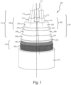
Figures 1 is a schematic perspective view partially sectioned of a power cable according to an embodiment of the present disclosure; -
Figure 2 is a schematic cross-section view of the power cable ofFigure 1 . - With reference to the figures, a power cable according to the present disclosure is schematically represented. The
power cable 100 comprises threeinsulated conductors 110 twisted one another along a longitudinal direction (A). - Each
insulated conductor 110 comprises oneelectric conductor 115 surrounded by apolymeric insulation system 200. Eachpolymeric insulation system 200 is sequentially formed by an innerpolymeric semiconductive layer 210, a polymeric insulatinglayer 220, and an outerpolymeric semiconductive layer 230. Eachinsulated conductor 100 may comprise also ametallic screen 240 arranged in a radially outer position with respect to the outerpolymeric semiconductive layer 230. Asemiconductive sheath 250 may be arranged in a radially outer position with respect to themetallic screen 240 like in the embodiment ofFigure 1 . - The three
insulated conductors 110 may be twisted to each other forming a cable core and abedding layer 260 surrounds the threeinsulated conductors 110. - The
power cable 100 also may comprise a filler (not illustrated) placed inside the space between the cable core and thebedding layer 260. - The filler, in particular, may be made of an extruded polymeric material or of polymeric filaments, or may be in form of three shaped elements each defining a plurality of spaces that can be used as seats for optical fiber cables (not illustrated).
- A
non-metallic armour 120, according to the present disclosure, surrounds thebedding layer 260. In the present embodiment, thenon-metallic armour 120 is made by two meshed tapes 120', 120'' helically wound around thebedding layer 260. Each meshed tape has an openness factor of at least 30% and a meshed tape tear resistance warp/weft of at least 200 N. - As apparent to the skilled person, an increase of the openness factor corresponds to a decrease of the meshed tape tear resistance warp/weft. Thus, a higher limit of the openness factor for the meshed tape of the disclosure is the one corresponding to the minimum value of the meshed tape tear resistance warp/weft. The same applies to the higher limit for the meshed tape tear resistance. Such higher limit value is the one corresponding to the minimum value of the openness factor.
- In the embodiment of
Figure 1 , the non-metallic armour is made by two meshed tapes 120', 120'' wherein a first meshed tape 120' surrounds thebedding layer 260 according to a first winding direction and a secondmeshed tape 120" surrounds the first meshed tape 120' according to a second winding direction. - The first winding direction may be opposite or may be substantially parallel to the second winding direction. In an embodiment, a single meshed tape has a thickness of about 0.5 to 2.5 mm. Therefore, for example, in the embodiments with two meshed tapes the overall thickness is about 1 to 5 mm.
- The
non-metallic armour 120 may be made of polymeric weft yarns and polymeric warp yarns interwoven to each other, optionally coated with a polymeric coating. - The
power cable 100 may comprise aserving layer 270 that surrounds the outer meshed tape like in the embodiment ofFigure 1 . - Each one of the
meshed tapes 120', 120" has an outer surface and an inner surface and at least the outer surface of the second meshed tape 120'' is at least partially covered by an adhesive layer (not illustrated) made, for example, by hot-melt glue that results to be placed between the outermeshed tape 120" and theserving layer 270. - In certain embodiments also the inner surface of at least the first meshed tape 120' is at least partially covered by an adhesive layer (not illustrated) made, for example, by hot-melt glue that results to be placed between the first meshed tape 120' and the
bedding layer 270. - The outer surface of the first meshed tape 120' and/or the inner surface of the second
meshed tape 120" may be at least partially covered by an adhesive layer. The presence of an adhesive layer on the outer surface of the first meshed tape 120' and, at the same time, on the inner surface of the secondmeshed tape 120" could be redundant. - In case of a plurality of meshed tapes one surrounding the other it may be provided also a third adhesive layer (not illustrated) made for example by hot-melt glue between two consecutive meshed tape 120' 120" like in the embodiment of
Figure 1 .
Claims (12)
- Power cable (100) comprising:- at least one insulated conductor (110) extending along a cable longitudinal direction (A);- a bedding layer (260) surrounding the at least one insulated conductor (110);- a non-metallic armour (120) surrounding the bedding layer (260), the non-metallic armour (120) being made by at least one meshed tape (120', 120'') helically wound onto the bedding layer (260), and having an openness factor of at least 30% and a meshed tape tear resistance warp/weft of at least 200 N according to DIN 53363 of 2003.
- Power cable (100) according to claim 1 having three insulated conductors (110) twisted one another along the cable longitudinal direction (A).
- Power cable (100) according to claim 1 wherein the at least one meshed tape (120', 120") has a thickness of from 0.5 to 2.5 mm.
- Power cable (100) according to claim 1 wherein the non-metallic armour (120) comprises at least two meshed tapes (120', 120'') wherein a first meshed tape (120') surrounds the bedding layer (260) and a second meshed tape (120'') surrounds the first meshed tape (120').
- Power cable (100) according to claim 1 wherein the non-metallic armour (120) is made of weft yarns and warp yarns interwoven to each other.
- Power cable (100) according to claim 5 the weft yarns and warp yarns are made of a polymeric material.
- Power cable (100) according to claim 5 the weft yarns and warp yarns are made of an inorganic and non-metallic material.
- Power cable (100) according to claim 5 the weft yarns and warp yarns are made of a natural material.
- Power cable (100) according to claim 5 wherein the weft yarns and warp yarns are coated with a coating.
- Power cable (100) according to claim 9 wherein the coating is made of a polymer material.
- Power cable (100) according to claim 1 wherein the at least one meshed tape (120', 120") has an outer surface and an inner surface wherein the outer surface is at least partially coated with a glue.
- Power cable (100) according to claim 9 wherein the inner surface of at least one meshed tape (120', 120") is at least partially coated with a glue.
Applications Claiming Priority (1)
| Application Number | Priority Date | Filing Date | Title |
|---|---|---|---|
| IT102023000000684A IT202300000684A1 (en) | 2023-01-18 | 2023-01-18 | ELECTRIC CABLE WITH NON-METALLIC TAPE ARMOUR. |
Publications (1)
| Publication Number | Publication Date |
|---|---|
| EP4404218A1 true EP4404218A1 (en) | 2024-07-24 |
Family
ID=85685208
Family Applications (1)
| Application Number | Title | Priority Date | Filing Date |
|---|---|---|---|
| EP24152413.1A Pending EP4404218A1 (en) | 2023-01-18 | 2024-01-17 | Power cable with non-metallic tape armour |
Country Status (7)
| Country | Link |
|---|---|
| US (1) | US20240242855A1 (en) |
| EP (1) | EP4404218A1 (en) |
| CN (1) | CN118366701A (en) |
| AR (1) | AR131616A1 (en) |
| AU (1) | AU2024200144A1 (en) |
| CA (1) | CA3224938A1 (en) |
| IT (1) | IT202300000684A1 (en) |
Citations (8)
| Publication number | Priority date | Publication date | Assignee | Title |
|---|---|---|---|---|
| GB836660A (en) | 1956-11-02 | 1960-06-09 | Montedison Spa | Electric cables for telecommunication purposes |
| US7555182B2 (en) | 2005-03-29 | 2009-06-30 | Reynolds Packaging Llc | Multi-layered water blocking cable armor laminate containing water swelling fabrics and associated methods of manufacture |
| US20130000948A1 (en) * | 2009-12-17 | 2013-01-03 | Giovanni Joseph Ida Henssen | Electrical cable |
| US20160358693A1 (en) | 2014-08-26 | 2016-12-08 | Shandong Hualing Gable Co.Ltd. | Class 1E cable for third generation passive nuclear power plant in mild environment and manufacturing method thereof |
| CN110690004A (en) * | 2019-11-21 | 2020-01-14 | 金杯电工衡阳电缆有限公司 | Mine use nitrile composite insulated tensile cable |
| KR20200144529A (en) * | 2018-12-10 | 2020-12-29 | 넥쌍 | High-shielding light-weight cables including shielding layer of polymer-carbon composite |
| CN214796823U (en) * | 2021-05-11 | 2021-11-19 | 江苏上上电缆集团有限公司 | Compound high temperature travelling cable |
| WO2022067934A1 (en) | 2020-09-29 | 2022-04-07 | 安徽华宇电缆集团有限公司 | Special degaussing cable for fixed winding for underwater vehicle |
Family Cites Families (7)
| Publication number | Priority date | Publication date | Assignee | Title |
|---|---|---|---|---|
| JPH062174Y2 (en) * | 1985-07-23 | 1994-01-19 | 古河電気工業株式会社 | Water-blocking rubber, plastic insulated power cable |
| GB0719215D0 (en) * | 2007-10-02 | 2007-11-14 | Wellstream Int Ltd | Thermal insulation of flexible pipes |
| WO2010126099A1 (en) * | 2009-04-28 | 2010-11-04 | 財団法人 国際超電導産業技術研究センター | Current terminal structure of superconducting wire material and superconducting cable having this current terminal structure |
| EP2605908B1 (en) * | 2010-08-17 | 2020-11-11 | Low & Bonar Gmbh | Composite material with coating material |
| KR102238971B1 (en) * | 2014-02-21 | 2021-04-12 | 엘에스전선 주식회사 | Termination connection box for DC cable |
| DE202018100248U1 (en) * | 2018-01-17 | 2018-01-23 | Certoplast Technische Klebebänder Gmbh | Abrasion-resistant adhesive tape |
| JP7243433B2 (en) * | 2019-05-20 | 2023-03-22 | 住友電気工業株式会社 | CABLE CONNECTION STRUCTURE, CABLE CONNECTION STRUCTURE MEMBER, AND CABLE CONNECTION STRUCTURE MANUFACTURING METHOD |
-
2023
- 2023-01-18 IT IT102023000000684A patent/IT202300000684A1/en unknown
- 2023-12-28 CA CA3224938A patent/CA3224938A1/en active Pending
-
2024
- 2024-01-10 AU AU2024200144A patent/AU2024200144A1/en active Pending
- 2024-01-16 AR ARP240100090A patent/AR131616A1/en unknown
- 2024-01-17 EP EP24152413.1A patent/EP4404218A1/en active Pending
- 2024-01-17 CN CN202410072021.8A patent/CN118366701A/en active Pending
- 2024-01-17 US US18/415,132 patent/US20240242855A1/en active Pending
Patent Citations (8)
| Publication number | Priority date | Publication date | Assignee | Title |
|---|---|---|---|---|
| GB836660A (en) | 1956-11-02 | 1960-06-09 | Montedison Spa | Electric cables for telecommunication purposes |
| US7555182B2 (en) | 2005-03-29 | 2009-06-30 | Reynolds Packaging Llc | Multi-layered water blocking cable armor laminate containing water swelling fabrics and associated methods of manufacture |
| US20130000948A1 (en) * | 2009-12-17 | 2013-01-03 | Giovanni Joseph Ida Henssen | Electrical cable |
| US20160358693A1 (en) | 2014-08-26 | 2016-12-08 | Shandong Hualing Gable Co.Ltd. | Class 1E cable for third generation passive nuclear power plant in mild environment and manufacturing method thereof |
| KR20200144529A (en) * | 2018-12-10 | 2020-12-29 | 넥쌍 | High-shielding light-weight cables including shielding layer of polymer-carbon composite |
| CN110690004A (en) * | 2019-11-21 | 2020-01-14 | 金杯电工衡阳电缆有限公司 | Mine use nitrile composite insulated tensile cable |
| WO2022067934A1 (en) | 2020-09-29 | 2022-04-07 | 安徽华宇电缆集团有限公司 | Special degaussing cable for fixed winding for underwater vehicle |
| CN214796823U (en) * | 2021-05-11 | 2021-11-19 | 江苏上上电缆集团有限公司 | Compound high temperature travelling cable |
Also Published As
| Publication number | Publication date |
|---|---|
| CN118366701A (en) | 2024-07-19 |
| AR131616A1 (en) | 2025-04-16 |
| AU2024200144A1 (en) | 2024-08-01 |
| IT202300000684A1 (en) | 2024-07-18 |
| CA3224938A1 (en) | 2025-05-08 |
| US20240242855A1 (en) | 2024-07-18 |
Similar Documents
| Publication | Publication Date | Title |
|---|---|---|
| US5216202A (en) | Metal-shielded cable suitable for electronic devices | |
| EP3623854B1 (en) | Optical cables for harsh environments | |
| US9378865B2 (en) | High strength tether for transmitting power and communications signals | |
| US4497537A (en) | Electric and/or optical cable | |
| CN101707067A (en) | Low-smoke halogen-free flame-retardant multifunctional armored cable for ship and marine engineering | |
| CN116682605B (en) | Cross-linked polyethylene insulated medium-high voltage power cable | |
| CN216719546U (en) | Reinforced coal mining machine cable | |
| CN111009342A (en) | Temperature-resistant cable | |
| US20240242855A1 (en) | Power cable with non-metallic tape armour | |
| CN213781660U (en) | Compound longitudinal watertight cable for ships | |
| US11177054B2 (en) | Armoured cable for transporting alternate current | |
| EP3811384B1 (en) | Armoured power cable | |
| BR102024000807A2 (en) | POWER CABLE | |
| GB2101392A (en) | An electric and/or optical cable | |
| JP2984071B2 (en) | Electronic equipment cable | |
| RU90253U1 (en) | ELECTRICAL WIRE OR CABLE (OPTIONS) | |
| GB2101798A (en) | Electric cable | |
| RU217369U1 (en) | HIGH-FREQUENCY COMBINED CABLE FOR UNDERWATER OBJECTS | |
| CN222883273U (en) | Anti-twisting loose strand lead sheathed low voltage armored cable | |
| CN220584960U (en) | Mine is with flexible antitorque commentaries on classics middling pressure trailing cable | |
| RU215403U1 (en) | Power cable for voltage 6-20 kV | |
| CN215183207U (en) | Longitudinal watertight composite cable | |
| CN218729957U (en) | Low-voltage multi-core photoelectric composite submarine cable | |
| CN220913941U (en) | Cable with improved cable characteristics | |
| CN215770559U (en) | Offshore drilling platform top drive moving jumper wire composite cable |
Legal Events
| Date | Code | Title | Description |
|---|---|---|---|
| PUAI | Public reference made under article 153(3) epc to a published international application that has entered the european phase |
Free format text: ORIGINAL CODE: 0009012 |
|
| STAA | Information on the status of an ep patent application or granted ep patent |
Free format text: STATUS: THE APPLICATION HAS BEEN PUBLISHED |
|
| AK | Designated contracting states |
Kind code of ref document: A1 Designated state(s): AL AT BE BG CH CY CZ DE DK EE ES FI FR GB GR HR HU IE IS IT LI LT LU LV MC ME MK MT NL NO PL PT RO RS SE SI SK SM TR |
|
| STAA | Information on the status of an ep patent application or granted ep patent |
Free format text: STATUS: REQUEST FOR EXAMINATION WAS MADE |
|
| 17P | Request for examination filed |
Effective date: 20250122 |