EP4404194A1 - Mehrkanal-echounterdrückungsverfahren und zugehörige vorrichtung - Google Patents
Mehrkanal-echounterdrückungsverfahren und zugehörige vorrichtung Download PDFInfo
- Publication number
- EP4404194A1 EP4404194A1 EP22897378.0A EP22897378A EP4404194A1 EP 4404194 A1 EP4404194 A1 EP 4404194A1 EP 22897378 A EP22897378 A EP 22897378A EP 4404194 A1 EP4404194 A1 EP 4404194A1
- Authority
- EP
- European Patent Office
- Prior art keywords
- far
- microphone
- microphone signal
- signal
- frequency domain
- Prior art date
- Legal status (The legal status is an assumption and is not a legal conclusion. Google has not performed a legal analysis and makes no representation as to the accuracy of the status listed.)
- Pending
Links
Images


Classifications
-
- H—ELECTRICITY
- H04—ELECTRIC COMMUNICATION TECHNIQUE
- H04R—LOUDSPEAKERS, MICROPHONES, GRAMOPHONE PICK-UPS OR LIKE ACOUSTIC ELECTROMECHANICAL TRANSDUCERS; ELECTRIC HEARING AIDS; PUBLIC ADDRESS SYSTEMS
- H04R3/00—Circuits for transducers
- H04R3/02—Circuits for transducers for preventing acoustic reaction, i.e. acoustic oscillatory feedback
-
- G—PHYSICS
- G10—MUSICAL INSTRUMENTS; ACOUSTICS
- G10L—SPEECH ANALYSIS TECHNIQUES OR SPEECH SYNTHESIS; SPEECH RECOGNITION; SPEECH OR VOICE PROCESSING TECHNIQUES; SPEECH OR AUDIO CODING OR DECODING
- G10L21/00—Speech or voice signal processing techniques to produce another audible or non-audible signal, e.g. visual or tactile, in order to modify its quality or its intelligibility
- G10L21/02—Speech enhancement, e.g. noise reduction or echo cancellation
- G10L21/0208—Noise filtering
-
- H—ELECTRICITY
- H04—ELECTRIC COMMUNICATION TECHNIQUE
- H04M—TELEPHONIC COMMUNICATION
- H04M9/00—Arrangements for interconnection not involving centralised switching
- H04M9/08—Two-way loud-speaking telephone systems with means for conditioning the signal, e.g. for suppressing echoes for one or both directions of traffic
-
- G—PHYSICS
- G10—MUSICAL INSTRUMENTS; ACOUSTICS
- G10L—SPEECH ANALYSIS TECHNIQUES OR SPEECH SYNTHESIS; SPEECH RECOGNITION; SPEECH OR VOICE PROCESSING TECHNIQUES; SPEECH OR AUDIO CODING OR DECODING
- G10L21/00—Speech or voice signal processing techniques to produce another audible or non-audible signal, e.g. visual or tactile, in order to modify its quality or its intelligibility
- G10L21/02—Speech enhancement, e.g. noise reduction or echo cancellation
- G10L21/0208—Noise filtering
- G10L2021/02082—Noise filtering the noise being echo, reverberation of the speech
Definitions
- This application relates to the technical field of audio processing, and in particular, to a multi-channel echo cancellation technology.
- a voice communication device needs to perform echo cancellation on the obtained multi-channel audio signals.
- the A terminal includes a microphone and a loudspeaker
- the B terminal also includes a microphone and a loudspeaker. A sound emitted by the loudspeaker of the B terminal may be transmitted to the A terminal through the microphone of the B terminal, resulting in an unnecessary echo, which needs to be cancelled.
- a current echo cancellation method usually brings large delay due to multiple echo paths, especially long echo paths. To reduce the delay, the order of a filter has to be increased, so that the calculation complexity of multi-channel echo cancellation is very high and the multi-channel echo cancellation cannot be really applied to production.
- this application provides a multi-channel echo cancellation method and a related apparatus, so that delay caused by an echo path and the like can be reduced, the calculation amount and calculation complexity of multi-channel echo cancellation can be greatly simplified, and better convergence performance can be achieved.
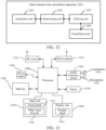
- the embodiments of this application provide a multi-channel echo cancellation apparatus.
- the multi-channel echo cancellation apparatus includes a first acquisition unit, a second acquisition unit, a determining unit, a filtering unit and a cancellation unit.
- the first acquisition unit is configured to obtaining a microphone signal outputted by a near-end microphone and including multiple microphone signal frames, and obtain multiple far-end audio signals respectively outputted by the multiple channels.
- the second acquisition unit is configured to obtain a first filter coefficient matrix corresponding to a k th microphone signal frame among the multiple microphone signal frames, where the first filter coefficient matrix includes frequency domain filter coefficients of filter sub-blocks corresponding to each of the multiple channels, and k is an integer greater than or equal to 1.
- the determining unit is configured to partition the plurality of far-end audio signals to obtain a k th frame of far-end audio signals, and partition each of the k th frame of far-end audio signals into blocks, to obtain a far-end frequency domain signal matrix corresponding to the k th microphone signal frame, the far-end frequency domain signal matrix comprising far-end frequency domain signals that is of each of the plurality channels and that respectively correspond to the filter sub-blocks.
- the filtering unit is configured to perform filtering processing by using the first filter coefficient matrix and the far-end frequency domain signal matrix to obtain an echo signal in the k th microphone signal frame;
- the cancellation unit is configured to perform echo cancellation by using a frequency domain signal of the k th microphone signal frame and the echo signal in the k th microphone signal frame to obtain a near-end audio signal outputted by the near-end microphone.
- the embodiments of this application provide a computer device.
- the computer device includes a processor and a memory:
- the embodiments of this application provide a computer-readable storage medium.
- the computer-readable storage medium is configured to store program codes, and the program codes are used for performing the method according to the first aspect.
- the embodiments of this application provide a computer program product.
- the computer program product includes a computer program, where the computer program implements the method according to the first aspect when being executed by a processor.
- the multiple far-end audio signals outputted by the multiple channels may be obtained, and when the near-end microphone outputs the k th microphone signal frame, the first filter coefficient matrix corresponding to the k th microphone signal frame may be obtained, where the first filter coefficient matrix includes the frequency domain filter coefficients of the filter sub-blocks corresponding to the multiple channels. Then, frame-partitioning and block-partitioning processing is performed according to the multiple far-end audio signals to determine a far-end frequency domain signal matrix, where the far-end frequency domain signal matrix includes the frequency domain signals of the filter sub-blocks corresponding to the multiple channels.
- the echo cancellation may be implemented quickly to obtain the near-end audio signal outputted by the near-end microphone.
- it is unnecessary to increase the order of the filter, but the calculation is transformed into the frequency domain and is combined with the frame-partitioning and block-partitioning processing, thereby reducing the delay caused by the echo path and the like, greatly reducing the calculation amount and calculation complexity of multi-channel echo cancellation, and achieving better convergence performance.
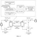
- the voice of a far-end user is collected by a far-end microphone 101 and transmitted to a voice communication device. After wireless or wired transmission, the voice of the far-end user reaches a near-end voice communication device, and is played through a near-end loudspeaker 202.
- the played voice (which may be referred to as a far-end audio signal during signal transmission) is collected by a near-end microphone 201 to form an acoustic echo signal, and the acoustic echo signal is transmitted and returned to a far-end voice communication device and played through a far-end loudspeaker 102, so that the far-end user hears his/her own echo.
- signals outputted by the far-end loudspeaker 102 include the echo signal and the near-end audio signal.
- AEC acoustic echo cancellation
- the embodiments of this application provide a multi-channel echo cancellation method.
- the method does not need to increase the order of the filter, but transforms the calculation into a frequency domain and combines the calculation with frame-partitioning and block-partitioning processing, thereby reducing the delay caused by the echo path and the like, greatly reducing the calculation amount and calculation complexity of multi-channel echo cancellation, and achieving better convergence performance.
- the method provided by the embodiments of this application may be applied to a related application of voice communication scenarios or a related voice communication device, in particular to various scenarios of multi-channel voice communication requiring echo cancellation, such as an audio and video conference application, an online classroom application, a telemedicine application, and a voice communication device capable of performing hands-free calls. These are not limited by the embodiments of this application.
- the method provided by the embodiments of this application may relate to the field of cloud technologies, such as cloud computing, cloud application, cloud education, and cloud conference.
- the system architecture includes a terminal 201 and a terminal 202, where the terminal 201 and the terminal 202 are voice communication devices, the terminal 201 may be a near-end voice communication device, and the terminal 202 may be a far-end voice communication device.
- the terminal 201 includes multiple loudspeakers 2011 and at least one microphone 2012, where the multiple loudspeakers 2011 are configured to play a far-end audio signal transmitted by the terminal 202, and the at least one microphone 2012 is configured to collect a near-end audio signal and may collect the far-end audio signal played by the multiple loudspeakers 2011 so as to form an echo signal.
- the terminal 202 may include a loudspeaker 2021 and a microphone 2022. Because the microphone 2012 collects the far-end audio signal played by the multiple loudspeakers 2011 while collecting the near-end audio signal, so to prevent a user corresponding to the terminal 202 from hearing his/her own echo, the terminal 202 may perform the multi-channel echo cancellation method provided by the embodiments of this application. This embodiment does not limit the number of the loudspeaker 2021 and the microphone 2022 included in the terminal 202; and the number of the loudspeaker 2021 may be one or more, and the number of the microphone 2022 may also be one or more.
- the terminal 201 and the terminal 202 may be a smart phone, a tablet computer, a notebook computer, a desktop computer, a smart loudspeaker, a smart watch, a vehicle-mounted terminal, a smart television, a dedicated audio and video conference device and the like, but are not limited thereto.
- FIG. 1 takes the case where the terminal 201 and the terminal 202 are smart phones as an example for description, and users respectively corresponding to the terminal 201 and the terminal 202 may perform voice communication.
- the embodiments of this application mainly use the scenario where the audio and video conference applications are installed on the terminal 201 and the terminal 202 so as to perform audio and video conference as an example for description.
- a server may support the terminal 201 and the terminal 202 in a background to provide a service (such as the audio and video conference) for the user.
- the server may be an independent physical server, a server cluster or a distributed system composed of multiple physical servers, or a cloud server providing a cloud computing service.
- the terminal 201, the terminal 202 and the server may be connected directly or indirectly through wired or wireless communication, which is not limited in this application.
- the terminal 202 may obtain multiple far-end audio signals, where the multiple far-end audio signals are respectively outputted by multiple channels.
- the multiple channels may be formed by multiple far-end loudspeakers, such as the loudspeakers 2011 in FIG. 1 .
- each of the loudspeakers corresponds to one of the multiple channels.
- the terminal 202 may perform echo cancellation through frame partitioning and block partitioning. Therefore, in a case that a near-end microphone outputs a k th microphone signal, the terminal 202 may obtain a first filter coefficient matrix corresponding to the k th microphone signal, where the first filter coefficient matrix includes frequency domain filter coefficients of filter sub-blocks corresponding to the multiple channels, thereby performing block partitioning on the filter to obtain the filter sub-blocks.
- the terminal 202 performs frame-partitioning and block-partitioning processing according to the multiple far-end audio signals, and determines a far-end frequency domain signal matrix corresponding to the k th microphone signal frame, where the far-end frequency domain signal matrix includes the far-end frequency domain signals of the filter sub-blocks corresponding to the multiple channels.
- the terminal 202 may quickly realize echo cancellation according to the frequency domain signal of the k th microphone signal frame and the echo signal in the k th microphone signal frame, and obtain the near-end audio signal outputted by the near-end microphone.
- the multi-channel echo cancellation method performed by the terminal 202 is taken as an example for description.
- the multi-channel echo cancellation method may be performed by the server corresponding to the terminal 202, or the multi-channel echo cancellation method may be performed by the terminal 202 and the server in cooperation.
- the embodiments of this application do not limit the performing subject of the multi-channel echo cancellation method.
- the multi-channel echo cancellation method provided by the embodiments of this application may be integrated into an echo canceller, and the echo canceller is installed into the related application of the voice communication scenario or the related voice communication device, so as to cancel the echo of other users collected by the near-end voice communication device, retain only the voice spoken by local users, and improve voice communication experience.
- FIG. 3 shows a flowchart of a multi-channel echo cancellation method. The method includes:
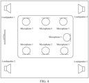
- FIG. 4 shows an example diagram of the multi-channel recording and playback of the dedicated audio and video conference device, including multiple loudspeakers (such as a loudspeaker 1, a loudspeaker 2, a loudspeaker 3, and a loudspeaker 4) and multiple microphones (such as a microphone 1, a microphone 2, ..., and a microphone 7). In some cases, one microphone may be included.
- FIG. 4 only takes multiple microphones as an example.
- the far-end audio signals transmitted by the multiple loudspeakers will be transmitted back to the far-end terminal to form the echo signal.
- the far-end audio signals played by the loudspeakers are reflected by obstacles such as walls, floors and ceilings, and the reflected voices and direct voices (that is, unreflected far-end audio signals) are picked up by microphones to form echo signals, so the multi-channel echo cancellation is required.
- the echo canceller may be installed into the dedicated audio and video conference device.
- a user a enters an online conference room, and the user a turns on the microphone and starts to speak, as shown in a user interface in FIG. 5 .
- the voice of the user a is collected by the microphone, and the voices of other users in the online conference are also collected by the microphone after being played through the loudspeaker of the terminal, so that other users online can hear their own voices, that is, the echo signals, while hearing the voice of the user a, so that the multi-channel echo cancellation is required.
- the echo canceller may be installed into the audio and video conference application.
- the multiple far-end audio signals are the audio signals outputted by the multiple loudspeakers included in the near-end terminal, and the far-end terminal may obtain multiple far-end audio signals.
- the embodiments of this application provide multiple exemplary methods to obtain the multiple far-end audio signals.
- One method may be that the far-end terminal directly determines the multiple audio signals according to the voice emitted by a corresponding user, and the other method may be that the near-end terminal determines the multiple far-end audio signals outputted by the loudspeaker, so that the far-end terminal may obtain the multiple far-end audio signals from the near-end terminal.
- S302 Obtain the first filter coefficient matrix corresponding to the k th microphone signal frame outputted by the near-end microphone, where the first filter coefficient matrix includes the frequency domain filter coefficients of the filter sub-blocks corresponding to each of the multiple channels.
- a filter is usually used for simulating the echo path.
- the echo signal obtained by the far-end audio signal passing through the echo path may be simulated by a processing result of processing the far-end audio signal by using the filter coefficients.
- the processing may be performing an operation on the filter coefficients and the far-end audio signal.
- the processing result may be obtained by multiplying the filter coefficients with the far-end audio signal.
- the far-end terminal may perform echo cancellation through frame partitioning and block partitioning. Therefore, During the echo cancellation performed for the k th microphone signal, the filter may be subjected to block partitioning.
- each part may be referred to as a filter sub-block, and each filter sub-block has a same length.
- the length of the filter is N
- the filter is partitioned into P filter sub-blocks
- the filtering function of the filter is embodied by filter coefficients.
- each filter sub-block may filter a corresponding far-end audio signal in parallel.
- the filtering function of the filter sub-block also needs to be embodied by corresponding filter coefficients obtained after the block-partitioning processing, so that each filter sub-block has the corresponding filter coefficient. Therefore, for each filter sub-block, the filter coefficient is used for operating with the far-end audio signal on the filter sub-block, thereby realizing the parallel processing of the far-end audio signals by the P parallel filter sub-blocks.
- the embodiments of this application may transform the filter coefficient of each filter sub-block to the frequency domain through the Fourier transform, thereby obtaining the frequency domain filter coefficient of each filter sub-block.
- the frequency domain filter coefficients of the filter sub-blocks corresponding to the multiple channels may form the filter coefficient matrix. In this way, for each frame of the microphone signal used for performing operations with the corresponding far-end audio signal, that is, the filter coefficient matrix corresponding to the frame of microphone signal.
- the far-end terminal may obtain the first filter coefficient matrix corresponding to the k th microphone signal frame, where the first filter coefficient matrix includes the frequency domain filter coefficients of the filter sub-blocks corresponding to the multiple channels.
- the near-end microphone here refers to the microphone on the near-end terminal.
- the k th microphone signal frame outputted by the near-end microphone is the k th microphone signal frame collected by the near-end microphone, including the near-end audio signal and the echo signal (that is, the echo signal generated based on the multiple far-end audio signals), where k is an integer greater than or equal to 1.
- the first filter coefficient matrix corresponding to the k th microphone signal frame may be acquired by obtaining a second filter coefficient matrix corresponding to a (k-1) th microphone signal frame.
- the second filter coefficient matrix includes the frequency domain filter coefficients of the filter sub-blocks corresponding to each channel when the near-end microphone outputs the (k-1) th microphone signal frame, where k is an integer greater than 1. Further, the second filter coefficient matrix is iteratively updated to obtain the first filter coefficient matrix.
- the first filter coefficient matrix used for the multi-channel echo cancellation of the current microphone signal frame may be iteratively updated according to the second filter coefficient matrix corresponding to a previous microphone signal frame (for example, the (k-1) th microphone signal frame), so that the filter coefficient matrix is continuously optimized and quickly converged.
- the filter may be a Kalman filter and the filter sub-blocks may be obtained by performing block-partitioning processing on a frequency domain Kalman filter, where the frequency domain Kalman filter includes at least two filter sub-blocks.
- Block-partitioned frequency-domain Kalman filtering is performed through a block-partitioned frequency-domain Kalman filter without performing nonlinear preprocessing on the far-end audio signal and without performing double-end intercom detection, thereby avoiding correlation interference in the multi-channel echo cancellation, reducing the calculation complexity and improving the convergence efficiency.
- a frequency domain observation signal model and a frequency domain state signal model may be constructed first.
- the principle of constructing the observation signal model and the state signal model is described below with reference to the block diagram of a system of multi-channel recording and playing shown in FIG. 6 .
- v(n) represents the near-end audio signal, and usually, the near-end audio signal is the sum of the near-end voice signal and background noise
- v(n) represents the near-end audio signal, which is usually the sum of the near-end voice signal and the background noise
- H represents the number of channels, that is, the number of loudspeakers.
- the observation signal model of the frequency domain is constructed based on a formula shown in (1).
- Frequency domain signal processing is based on frame processing.
- the echo path w i (n) is divided into P sub-blocks with equal length, and each sub-block may be referred to as the filter sub-block.
- W i ,p k F w i ,p k 0 L ⁇ 1
- 0 L ⁇ 1 represents an all-zero column vector with the number of dimensions being L ⁇ 1.
- x i (n) [x i (n), ... , x i (n - N + 1)] T
- frame-partitioning and block-partitioning processing is performed on the far-end audio signal of the p th filter sub-block of the i th channel, and the far-end audio signal is transformed to the frequency domain:
- x i ,p k diag F x i kL ⁇ pL ⁇ L , ... , x i kL ⁇ pL + L ⁇ 1 T
- diag ⁇ represents the operation of transforming a vector into a diagonal matrix.
- F [] represents the Fourier transform.
- v(kL + L - 1)] T are respectively the frequency domain signal of the k-th microphone signal frame and the frequency domain signal of the near-end audio signal
- G 01 is a windowing matrix, thereby ensuring that a result of cyclic convolution is consistent with that of linear convolution
- 0 1 ⁇ L is an all-zero matrix with the number of dimensions of 1 ⁇ L.
- X H,P-1 (k)] is a matrix composed of the frequency domain signals of the far-end audio signals of H channels, and may be referred to as the far-end frequency domain signal matrix;
- X(k) G 01 [X 10 (k), ... , X 1,P-1 (k), ... , X H,0 (k), ... , X H,P-1 (k)] is the first filter coefficient matrix corresponding to the k th microphone signal frame composed of all the filter sub-blocks of the H channels. So far, the frequency domain observation signal model under the framework of the multi-channel echo cancellation is constructed.
- a frequency domain state signal model is constructed.
- the above formula describes the change of the echo path with time by using the transfer parameter A and the energy of a real echo path.
- a process noise covariance matrix estimation method provided by the formula (10) may better cope with larger echo path changes, even for the larger parameter A.
- an accurate partitioned-block frequency domain Kalman filtering algorithm may be derived.
- the second filter coefficient matrix is updated iteratively.
- the first filter coefficient matrix may be obtained by obtaining the observation covariance matrix corresponding to the k th microphone signal frame and the state covariance matrix corresponding to the (k-1) th microphone signal frame, where the observation covariance matrix and the state covariance matrix are diagonal matrices, respectively representing the uncertainty of a residual signal prediction value estimation and a state estimation in the Kalman filtering.
- a gain coefficient is calculated, where the gain coefficient represents the influence of the residual signal prediction value estimation on the state estimation.
- the first filter coefficient matrix is determined according to the second filter coefficient matrix, the gain coefficient and the residual signal prediction value corresponding to the k th microphone signal frame, so that in the iterative updating process, the accuracy of the state estimation (that is, a new filter coefficient matrix such as the first filter coefficient matrix) is improved by continuously modifying the gain coefficient and the residual signal prediction value corresponding to the k th microphone signal frame.
- the observation covariance matrix corresponding to the k th microphone signal frame may be obtained by the following steps: perform filtering processing according to the second filter coefficient matrix and the far-end frequency domain signal matrix, and obtain the residual signal prediction value corresponding to the k th microphone signal frame; and calculate the observation covariance matrix corresponding to the k th microphone signal according to the residual signal prediction value corresponding to the k th microphone signal.
- the filtering processing according to the second filter coefficient matrix and the far-end frequency domain signal matrix may be as follows: perform product summation on the second filter coefficient matrix and the far-end frequency domain signal matrix, and the residual signal prediction value corresponding to the k th microphone signal frame may represent the echo signal possibly corresponding to a next microphone signal frame predicted based on the second filter coefficient matrix.
- E(k) represents the frequency domain representation of the residual signal prediction value corresponding to the k th microphone signal frame
- Y(k) represents the frequency domain signal of the k th microphone signal frame
- X i (k) represents the far-end frequency domain signal matrix corresponding to the k th microphone signal frame
- W i (k - 1) represents the second filter coefficient matrix corresponding to the (k-1) th microphone signal frame
- H is the number of channels
- L is the length of each filter sub-block
- i represents the subscript of each element in the matrix.
- the calculation may be combined with the observation covariance matrix corresponding to the (k-1) th microphone signal frame.
- ⁇ s (k) represents the observation covariance matrix corresponding to the (k-1) th microphone signal
- ⁇ is a smoothing factor and is set according to the actual experience
- E(k) is the frequency domain representation of the residual signal prediction value corresponding to the k th microphone signal frame
- ⁇ represents dot product operation
- diag ⁇ represents the operation of transforming the vector into the diagonal
- the state covariance matrix corresponding to the (k-1) th microphone signal frame may be obtained by calculating the state covariance matrix corresponding to the (k-1) th microphone signal frame according to the second filter coefficient matrix.
- P i,j (k - 1) represents the state covariance matrix corresponding to the (k-1) th microphone signal frame
- P i,j (k - 2) represents the state covariance matrix corresponding to a (k-2) th microphone signal frame
- K i (k - 1) represents the gain coefficient corresponding to (k-1) th microphone signal
- X i (k - 1) represents the far-end frequency domain signal matrix corresponding to the (k-1) th microphone signal frame
- W i (k - 1) represents the second filter coefficient matrix corresponding
- Some variables corresponding to the (k-1) th microphone signal may be calculated according to the variables corresponding to the previous microphone signal frame, or may be set initial values.
- the state covariance matrix corresponding to the (k-1) th microphone signal frame and the state covariance matrix corresponding to the (k-2) th microphone signal frame may also be set initial values.
- D x (k) is the gain estimation intermediate variable
- R is the frame shift
- M is the frame length
- X i (k) represents the far-end frequency domain signal matrix corresponding to the k th microphone signal frame
- P i,j (k - 1) represents the state covariance matrix corresponding to (k-1) th microphone signal frame
- X ⁇ j ⁇ k represents the conjugate transposition of the far-end frequency domain signal matrix corresponding to the k th microphone signal frame
- ⁇ s (k) represents the observed covariance matrix corresponding to the
- K i (k) represents the gain coefficient
- P i,j (k - 1) represents the state covariance matrix corresponding to the (k-1) th microphone signal frame
- X ⁇ j ⁇ k represents the conjugate transposition of the far-end frequency domain signal matrix corresponding to the k th microphone signal frame
- D x ⁇ 1 k inversely transform the gain estimation intermediate variable
- R is the frame shift
- M is the frame length
- j is the subscript of the elements in the matrix.
- S303 Partition the multiple far-end audio signals to obtain a k th frame of far-end audio signals, and partition each of the k th frame of far-end audio signals into blocks to obtain the far-end frequency domain signal matrix corresponding to the k th microphone signal frame, where the far-end frequency domain signal matrix includes far-end frequency domain signals that is of each of the multiple channels and that respectively correspond to the filter sub-blocks.
- S304 Perform filtering processing by using the first filter coefficient matrix and the far-end frequency domain signal matrix to obtain the echo signal in the k th microphone signal frame.
- the far-end audio signal may include multiple frames, and the embodiments of this application are to perform the echo cancellation for each microphone signal frame.
- the echo cancellation for the k th microphone signal frame it is necessary to select the far-end audio signal corresponding to the k th microphone signal frame from multiple frames of far-end audio signals to realize the echo cancellation in units of frames.
- the filter is partitioned to multiple filter sub-blocks to perform parallel processing on the far-end audio signal through the multiple filter sub-blocks, that is, each filter sub-block is used to process a part of the far-end audio signal.
- the far-end terminal partitions the multiple far-end audio signals to obtain a frame of far-end audio signals corresponding to the k th microphone signal frame, that is, far-end audio signals at the same time instant as the k th microphone signal frame in the time domain, and each of the frame of far-end audio signals is partitioned into multiple blocks of the same quantity as the filter sub-blocks, where each block corresponds to one filter sub-block, and multiple blocks corresponding to the multiple frames of the far-end audio signals form the far-end audio signal matrix.
- each filter sub-block processes a corresponding part of the far-end audio signal.
- the embodiments of this application may transform the far-end audio signal after frame-partitioning and block-partitioning processing to the frequency domain through the Fourier transform, thereby obtaining the frequency domain representation of the far-end audio signal, and correspondingly, the far-end audio signal matrix is transformed into the far-end frequency domain signal matrix.
- the far-end frequency domain signal matrix includes the far-end frequency domain signals of the filter sub-blocks corresponding to the multiple channels.
- the way to determine the far-end frequency domain signal matrix by performing frame-partitioning and block-partitioning processing according to the multiple far-end audio signals may be as follows: obtain the far-end frequency domain signal of each filter sub-block corresponding to the multiple channels according to a preset frame shift and a preset frame length by adopting an overlap reservation algorithm , and the far-end frequency domain signal of each filter sub-block corresponding to the multiple channels form the far-end frequency-domain signal matrix.
- the preset frame shift may be represented by R.
- the far-end audio signals x h (n) of H channels are partitioned.
- w h (n) is the time domain representation of the filter coefficient corresponding to the h th channel
- w h,l (n) is the time domain representation of the filter coefficient of an l th filter sub-block corresponding to the h th channel
- n represents the discrete sampling time.
- the filtering processing according to the first filter coefficient matrix and the far-end frequency domain signal matrix may be a product summation operation of X i (k) and W i (k) to obtain the echo signal in the k th microphone signal frame.
- S305 Perform the echo cancellation by using the frequency domain signal of the k th microphone signal frame and the echo signal in the k th microphone signal frame to obtain the near-end audio signal outputted by the near-end microphone.
- the far-end terminal may subtract the echo signal from the frequency domain signal of the k th microphone signal frame, thereby realizing the echo cancellation and obtaining the near-end audio signal outputted by the near-end microphone.
- the near-end microphone is located on the voice communication device, where the voice communication device may include a microphone which is the near-end microphone.
- the obtained near-end audio signal outputted by the near-end microphone is finally played to the far-end user.
- the voice communication device may include multiple microphones, for example, T microphones, where T is an integer greater than 1.
- the near-end microphone is a t th microphone of the T microphones, where 0 ⁇ t ⁇ T-1 and t is an integer.
- the obtained near-end audio signal outputted by the near-end microphone is the near-end audio signal outputted by each microphone.
- signal mixing may be performed on the near-end audio signals respectively outputted by the T microphones to obtain the target audio signal, thereby improving the quality of the target audio signal played to the far-end user through mixing.
- the near-end audio signals outputted by the T microphones are respectively S 0 , ..., and S T-1 .
- Signal mixing is performed on S 0 , ..., and S T-1 to obtain the target audio signal.
- the near-end audio signal may include the voice signal and the background noise
- the background noise included in the near-end audio signal may be cancelled.
- the T microphones may output T near-end audio signals, to avoid cancelling the background noise for each near-end audio signal, the background noise included in the target audio signal may be estimated after the target audio signal is obtained, so that the background noise may be cancelled from the target audio signal to obtain the near-end voice signal.
- the background noise cancellation of each near-end audio signal is avoided by performing signal mixing first and then cancelling the background noise, thereby reducing the calculation amount and improving the calculation efficiency.
- the multiple far-end audio signals outputted by the multiple channels may be obtained, and when the near-end microphone outputs the k th microphone signal frame, the first filter coefficient matrix corresponding to the k th microphone signal frame may be obtained, where the first filter coefficient matrix includes the frequency domain filter coefficients of the filter sub-blocks corresponding to the multiple channels. Then, frame-partitioning and block-partitioning processing is performed according to the multiple far-end audio signals to determine a far-end frequency domain signal matrix, where the far-end frequency domain signal matrix includes the frequency domain signals of the filter sub-blocks corresponding to the multiple channels.
- the echo cancellation may be implemented quickly to obtain the near-end audio signal outputted by the near-end microphone.
- it is unnecessary to increase the order of the filter, but the calculation is transformed into the frequency domain and is combined with the frame-partitioning and block-partitioning processing, thereby reducing the delay caused by the echo path and the like, greatly reducing the calculation amount and calculation complexity of multi-channel echo cancellation, and achieving better convergence performance.
- Method 1 may be referenced to FIG. 7 and Method 2 may be referenced to FIG. 8 .
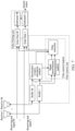
- Method 1 is to use an echo filter to perform echo filtering on M paths of receiving-end signals to obtain M paths of filtered receiving-end signals, and subtract the M paths of filtered receiving-end signals from sending-end signals to obtain system output signals that cancel the echo of the receiving end; at the same time, a buffer (a buffer 1, ..., and a buffer M) is used for buffering M paths of receiving-end signals and calculating a decorrelation matrix according to the buffered M paths of receiving-end signals within each preset length.
- a buffer a buffer 1, ..., and a buffer M
- the decorrelation matrix is used for decomposing the buffered M paths of receiving-end signals into M paths of decorrelated receiving-end signals and calculating the update amount of the echo filter according to the decorrelation matrix, the M paths of decorrelated receiving-end signals and the feedback system output signals.
- Method 1 actually introduces a preprocessing method.
- the preprocessing method can reduce the voice quality and the user experience while removing correlation between channels. At the same time, the setting of parameters needs to be balanced between the two.
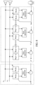
- Method 2 is to model each echo path independently, and finally copy independently modeled coefficients to a new filter.
- this solution may estimate each echo path more accurately.
- NLMS normalized least mean square
- the method provided by the embodiments of this application has a significant performance advantage. It is unnecessary to perform any nonlinear preprocessing on the far-end audio signal and to adopt a double-end intercom detection method, thereby avoiding the correlation interference in the multi-channel echo cancellation, reducing the calculation complexity, and improving the convergence efficiency.
- FIG. 9 is an example diagram of an MSD curve of the above three echo cancellation methods in a single-speaking state, where the larger the value of the MSD is, the worse the performance is.
- the multi-channel echo cancellation method provided by the embodiments of this application achieves better performance quickly, that is, the value of MSD decreases rapidly, and the echo path changes in seconds (an echo path mutation is simulated by multiplying the echo path by -1), thereby reducing the performance of all three echo cancellation methods and increasing the value of MSD immediately.
- the multi-channel echo cancellation method provided by the embodiments of this application achieves better performance quickly after the echo path mutation. It can be seen that the performance of the multi-channel echo cancellation method provided by the embodiments of this application is superior to that of Method 1 and Method 2.
- FIG. 11 is an example diagram of the MSD curve of the above three echo cancellation methods in a double-speaking state. It can be seen from FIG. 10 that the near-end audio signal appears in 20s-30s and 40s-50s respectively. It can be seen from FIG. 11 that Method 1 and Method 2 diverge rapidly when there is interference of the near-end audio signal in two time intervals of 20s-30s and 40s-50s, that is, the value of MSD becomes obviously larger, resulting causing performance degradation.
- the multi-channel echo cancellation method provided by the embodiments of this application has a rapid decline in MSD, that is, the method has good robustness to the interference of the near-end audio signal in a case of no double-speaking detection.
- This application may be further combined to provide more implementations based on the implementations provided in the above aspects.
- the embodiments of this application further provide a multi-channel echo cancellation apparatus.
- the apparatus 1200 includes an acquisition unit 1201, a determining unit 1202, a filtering unit 1203 and a cancellation unit 1204.
- the acquiring unit 1201 is configured to obtain a microphone signal outputted by a near-end microphone and including multiple microphone signal frames, and obtain multiple far-end audio signals, where the multiple far-end audio signals are respectively outputted by the multiple channels.
- the acquisition unit 1201 is further configured to obtain a first filter coefficient matrix corresponding to the k th microphone signal frame among the plurality of microphone signal frames, where the first filter coefficient matrix includes frequency domain filter coefficients of filter sub-blocks corresponding to each of the multiple channels, and k is an integer greater than or equal to 1.
- the determining unit 1202 is configured to partition the plurality of far-end audio signals to obtain a k th frame of far-end audio signals, and partition each of the k th frame of far-end audio signals into blocks, to obtain a far-end frequency domain signal matrix corresponding to the k th microphone signal frame, the far-end frequency domain signal matrix comprising far-end frequency domain signals that is of each of the plurality channels and that respectively correspond to the filter sub-blocks.
- the filtering unit 1203 is configured to perform filtering processing by using the first filter coefficient matrix and the far-end frequency domain signal matrix to obtain the echo signal in the k th microphone signal frame.
- the cancellation unit 1204 is configured to perform the echo cancellation by using the frequency domain signal of the k th microphone signal frame and the echo signal in the k th microphone signal frame to obtain a near-end audio signal outputted by the near-end microphone.
- the acquisition unit 1201 is specifically configured to:
- the acquisition unit 1201 is specifically configured to:
- the acquisition unit 1201 is specifically configured to:
- the determining unit 1202 is configured to:
- the near-end microphone is located on the voice communication device.
- the voice communication device includes T microphones, where T is an integer greater than 1, the near-end microphone is a t th microphone of the T microphones, 0 ⁇ t ⁇ T-1 and t is an integer.
- the apparatus further includes an audio mixing unit.
- the audio mixing unit is configured to perform signal mixing on the near-end audio signals respectively outputted by the T microphones to obtain the microphone signal.
- the apparatus further includes an estimation unit.
- the estimation unit is configured to estimate the background noise included in the target audio signal.
- the cancellation unit 1204 is further configured to cancel the background noise from the microphone signal to obtain the near-end voice signal.
- the embodiments of this application further provide a computer device.
- the computer device may be a voice communication device.
- the voice communication device may be a terminal. Taking the case where the terminal is a smart phone as an example:
- FIG. 13 is a block diagram of a part of a structure of a smart phone according to an embodiment of this application.
- the smart phone includes: a radio frequency (RF) circuit 1310, a memory 1320, an input unit 1330, a display unit 1340, a sensor 1350, an audio-frequency circuit 1360, a wireless fidelity (WiFi) module 1370, a processor 1380, a power supply 1390 and other components.
- the input unit 1330 may include a touch panel 1331 and another input device 1332.
- the display unit 1340 may include a display panel 1341.
- the audio circuit 1360 may include a loudspeaker 1361 and a microphone 1362.
- the smart phone structure shown in FIG. 13 does not constitute a limitation to the smart phone, may include more or fewer parts than those shown in the figure, or may combine some parts, or may arrange different parts.
- the memory 1320 may be configured to store software programs and modules, and the processor 1380 performs various functional applications and data processing of the smart phone by running the software programs and modules stored in the memory 1320.
- the memory 1320 may mainly include a program storage area and a data storage area.
- the program storage area may store an operating system, an application program required by at least one function (for example, a sound playing function and an image playing function), or the like.
- the data storage area may store data (such as audio data and a phone book) created according to the use of the smart phone.
- the memory 1320 may include a high-speed random access memory, and may further include a nonvolatile memory, such as at least one disk storage device, a flash memory device or other volatile solid-state storage devices.
- the processor 1380 is a control center of the smart phone, connects various parts of the whole smart phone by various interfaces and lines, and performs various functions and processes data of the smart phone by running or executing software programs and/or modules stored in the memory 1320 and recalling data stored in the memory 1320, thereby overally monitoring the smart phone.
- the processor 1380 may include one or more processing units.
- the processor 1380 may integrate an application processor and a modem processor, where the application processor mainly processes an operating system, a user interface, and an application program; and the modem processor mainly processes wireless communication. It may be understood that the modem processor described above may also not be integrated into the processor 1380.
- the processor 1380 in the smart phone may perform the multi-channel echo cancellation method provided by the embodiments of this application.
- FIG. 14 is a structural diagram of a server 1400 according to an embodiment of this application.
- the server 1400 may vary greatly due to different configurations or performance, and may include one or more central processing units (CPU) 1422 (for example, one or more processors) and a memory 1432.
- the one or more storage media 1430 (for example, one or more mass storage devices) for storing an application program 1442 or data 1444.
- the memory 1432 and the storage medium 1430 may be transient storage or persistent storage.
- the program stored in the storage medium 1430 may include one or more modules (not shown in the figure). Each of the modules may include a series of instruction operations in the server.
- the central processor 1422 may be configured to communicate with the storage medium 1430 to perform a series of instruction operations in the storage medium 1430 on the server 1400.
- the server 1400 may further include one or more power supplies 1426, one or more wired or wireless network interfaces 1450, one or more input and output interfaces 1458, and/or one or more operating systems 1441, such as Windows Server TM , Mac OS X TM , Unix TM , Linux TM and FreeBSD TM .
- operating systems 1441 such as Windows Server TM , Mac OS X TM , Unix TM , Linux TM and FreeBSD TM .
- the steps performed by the central processor 1422 in the server 1400 may be implemented based on the structure shown in FIG. 14 .
- a computer-readable storage medium configured to store program codes, and the program codes are used for performing the multi-channel echo cancellation method in the foregoing embodiments.
- a computer program product or a computer program includes a computer instruction, and the computer instruction is stored in the computer-readable storage medium.
- the processor of the computer device reads the computer instruction from the computer-readable storage medium, and executes the computer instruction to cause the computer device to perform the methods provided in various optional implementations of the above embodiments.
- the disclosed system, apparatus and method may be implemented in other manners.
- the embodiments of the apparatus described above is only schematic, for example, division into the units is only logical function division. There may be other division, manners in actual implementation, for example, multiple units or components may be combined or integrated into other systems, or some features may be ignored or not performed.
- the displayed or discussed mutual couplings or direct couplings or communication connections may be implemented by using some interfaces.
- the indirect couplings or communication connections between apparatuses or units may be implemented in electronic, mechanical, or other forms.
- the units described as separate parts may or may not be physically separated, and parts shown as units may or may not be physical units, that is, may be located in one location, or may be distributed on multiple network units. Some or all of the units may be selected according to actual needs to achieve the objective of the solutions of the embodiments.
- the integrated unit if implemented in the form of a software functional unit and sold or used as a stand-alone product, may be stored in a computer readable storage medium.
- a computer readable storage medium including several instructions to enable a computer device (which may be a personal computer, a server, or a network device) to perform all or part of the steps of the methods described in the embodiments of this application.
- the storage medium includes: any medium that can store program code, such as a USB flash disk, a removable hard disk, a read-only memory (ROM), a random access memory (RAM), a magnetic disk, or an optical disc.
Landscapes
- Engineering & Computer Science (AREA)
- Signal Processing (AREA)
- Acoustics & Sound (AREA)
- Physics & Mathematics (AREA)
- Health & Medical Sciences (AREA)
- Human Computer Interaction (AREA)
- Audiology, Speech & Language Pathology (AREA)
- Quality & Reliability (AREA)
- Computational Linguistics (AREA)
- Multimedia (AREA)
- General Health & Medical Sciences (AREA)
- Otolaryngology (AREA)
- Cable Transmission Systems, Equalization Of Radio And Reduction Of Echo (AREA)
Applications Claiming Priority (2)
| Application Number | Priority Date | Filing Date | Title |
|---|---|---|---|
| CN202111424702.9A CN116189697A (zh) | 2021-11-26 | 2021-11-26 | 一种多通道回声消除方法和相关装置 |
| PCT/CN2022/122387 WO2023093292A1 (zh) | 2021-11-26 | 2022-09-29 | 一种多通道回声消除方法和相关装置 |
Publications (2)
| Publication Number | Publication Date |
|---|---|
| EP4404194A1 true EP4404194A1 (de) | 2024-07-24 |
| EP4404194A4 EP4404194A4 (de) | 2024-12-25 |
Family
ID=86442788
Family Applications (1)
| Application Number | Title | Priority Date | Filing Date |
|---|---|---|---|
| EP22897378.0A Pending EP4404194A4 (de) | 2021-11-26 | 2022-09-29 | Mehrkanal-echounterdrückungsverfahren und zugehörige vorrichtung |
Country Status (4)
| Country | Link |
|---|---|
| US (1) | US20230403506A1 (de) |
| EP (1) | EP4404194A4 (de) |
| CN (1) | CN116189697A (de) |
| WO (1) | WO2023093292A1 (de) |
Families Citing this family (3)
| Publication number | Priority date | Publication date | Assignee | Title |
|---|---|---|---|---|
| US12231602B2 (en) * | 2021-08-04 | 2025-02-18 | Nokia Technologies Oy | Apparatus, methods and computer programs for performing acoustic echo cancellation |
| EP4202922A1 (de) * | 2021-12-23 | 2023-06-28 | GN Audio A/S | Audiovorrichtung und verfahren zur sprecherextraktion |
| CN119626242B (zh) * | 2024-12-30 | 2025-08-29 | 马栏山音视频实验室 | 一种回声消除方法、装置、设备及存储介质 |
Family Cites Families (14)
| Publication number | Priority date | Publication date | Assignee | Title |
|---|---|---|---|---|
| WO2002017487A1 (en) * | 2000-08-21 | 2002-02-28 | Koninklijke Philips Electronics N.V. | Partioned block frequency domain adaptive filter |
| US8924337B2 (en) * | 2011-05-09 | 2014-12-30 | Nokia Corporation | Recursive Bayesian controllers for non-linear acoustic echo cancellation and suppression systems |
| EP3125429A1 (de) * | 2015-07-28 | 2017-02-01 | Fraunhofer-Gesellschaft zur Förderung der angewandten Forschung e.V. | Adaptive filtervorrichtung der partitionierten blockfrequenzdomäne mit adaptationsmodulen und korrekturmodulen |
| US9881630B2 (en) * | 2015-12-30 | 2018-01-30 | Google Llc | Acoustic keystroke transient canceler for speech communication terminals using a semi-blind adaptive filter model |
| CN111213359B (zh) * | 2017-10-04 | 2021-09-10 | 主动音频有限公司 | 回声消除器和用于回声消除器的方法 |
| CN108806709B (zh) * | 2018-06-13 | 2022-07-12 | 南京大学 | 基于频域卡尔曼滤波的自适应声回声抵消方法 |
| DE102018122438A1 (de) * | 2018-09-13 | 2020-03-19 | Harman Becker Automotive Systems Gmbh | Akustische Echounterdrückung mit Raumänderungserfassung |
| CN110956973A (zh) * | 2018-09-27 | 2020-04-03 | 深圳市冠旭电子股份有限公司 | 一种回声消除方法、装置及智能终端 |
| CN112242145B (zh) * | 2019-07-17 | 2025-01-07 | 南京人工智能高等研究院有限公司 | 语音滤波方法、装置、介质和电子设备 |
| CN111341336B (zh) * | 2020-03-16 | 2023-08-08 | 北京字节跳动网络技术有限公司 | 一种回声消除方法、装置、终端设备及介质 |
| EP4199368B1 (de) * | 2020-08-12 | 2025-08-20 | Auzdsp Co., Ltd. | Adaptiver verzögerungsdiversitätsfilter und verfahren zu dessen verwendung |
| CN112820311A (zh) * | 2021-04-16 | 2021-05-18 | 成都启英泰伦科技有限公司 | 一种基于空间预测的回声消除方法及装置 |
| CN113470675B (zh) * | 2021-06-30 | 2024-06-25 | 北京小米移动软件有限公司 | 音频信号处理方法及装置 |
| CN113489855B (zh) * | 2021-06-30 | 2024-03-19 | 北京小米移动软件有限公司 | 声音处理方法、装置、电子设备和存储介质 |
-
2021
- 2021-11-26 CN CN202111424702.9A patent/CN116189697A/zh active Pending
-
2022
- 2022-09-29 EP EP22897378.0A patent/EP4404194A4/de active Pending
- 2022-09-29 WO PCT/CN2022/122387 patent/WO2023093292A1/zh not_active Ceased
-
2023
- 2023-08-25 US US18/456,054 patent/US20230403506A1/en active Pending
Also Published As
| Publication number | Publication date |
|---|---|
| EP4404194A4 (de) | 2024-12-25 |
| WO2023093292A9 (zh) | 2024-09-19 |
| CN116189697A (zh) | 2023-05-30 |
| WO2023093292A1 (zh) | 2023-06-01 |
| US20230403506A1 (en) | 2023-12-14 |
Similar Documents
| Publication | Publication Date | Title |
|---|---|---|
| EP4404194A1 (de) | Mehrkanal-echounterdrückungsverfahren und zugehörige vorrichtung | |
| US9768829B2 (en) | Methods for processing audio signals and circuit arrangements therefor | |
| JP3506138B2 (ja) | 複数チャンネルエコーキャンセル方法、複数チャンネル音声伝送方法、ステレオエコーキャンセラ、ステレオ音声伝送装置および伝達関数演算装置 | |
| US20100217590A1 (en) | Speaker localization system and method | |
| US9210504B2 (en) | Processing audio signals | |
| US7831035B2 (en) | Integration of a microphone array with acoustic echo cancellation and center clipping | |
| US7773743B2 (en) | Integration of a microphone array with acoustic echo cancellation and residual echo suppression | |
| EP2749016B1 (de) | Verarbeitung von tonsignalen | |
| CN111951819A (zh) | 回声消除方法、装置及存储介质 | |
| US8462962B2 (en) | Sound processor, sound processing method and recording medium storing sound processing program | |
| CN110265054B (zh) | 语音信号处理方法、装置、计算机可读存储介质和计算机设备 | |
| JP5391103B2 (ja) | 多チャネルエコー消去方法、多チャネルエコー消去装置、多チャネルエコー消去プログラム及びその記録媒体 | |
| CN114143668B (zh) | 音频信号处理、混响检测和会议方法、设备及存储介质 | |
| US20260057897A1 (en) | Method for processing audio signal, electronic device, and computer-readable storage medium | |
| JP2012039441A (ja) | 多チャネルエコー消去方法、多チャネルエコー消去装置及びそのプログラム | |
| CN112997249B (zh) | 语音处理方法、装置、存储介质及电子设备 | |
| CN115175063A (zh) | 啸叫抑制方法、装置、音响及扩音系统 | |
| Wung | A system approach to multi-channel acoustic echo cancellation and residual echo suppression for robust hands-free teleconferencing | |
| JP4920511B2 (ja) | マルチチャンネルエコーキャンセラ | |
| CN113783551A (zh) | 滤波器系数确定方法、回声消除方法及装置 | |
| HK40087228A (zh) | 一种多通道回声消除方法和相关装置 | |
| JP2002261659A (ja) | 多チャネルエコーキャンセル方法、その装置、そのプログラム及び記録媒体 | |
| JP6075783B2 (ja) | エコー消去装置、エコー消去方法及びプログラム | |
| Ruiz et al. | Distributed combined acoustic echo cancellation and noise reduction using GEVD-based distributed adaptive node specific signal estimation with prior knowledge | |
| Fîciu et al. | A Decomposition-Based RLS Algorithm for Stereophonic Acoustic Echo Cancellation |
Legal Events
| Date | Code | Title | Description |
|---|---|---|---|
| STAA | Information on the status of an ep patent application or granted ep patent |
Free format text: STATUS: THE INTERNATIONAL PUBLICATION HAS BEEN MADE |
|
| PUAI | Public reference made under article 153(3) epc to a published international application that has entered the european phase |
Free format text: ORIGINAL CODE: 0009012 |
|
| STAA | Information on the status of an ep patent application or granted ep patent |
Free format text: STATUS: REQUEST FOR EXAMINATION WAS MADE |
|
| 17P | Request for examination filed |
Effective date: 20240418 |
|
| AK | Designated contracting states |
Kind code of ref document: A1 Designated state(s): AL AT BE BG CH CY CZ DE DK EE ES FI FR GB GR HR HU IE IS IT LI LT LU LV MC MK MT NL NO PL PT RO RS SE SI SK SM TR |
|
| REG | Reference to a national code |
Ref country code: DE Ref legal event code: R079 Free format text: PREVIOUS MAIN CLASS: G10L0021020800 Ipc: H04M0009080000 |
|
| A4 | Supplementary search report drawn up and despatched |
Effective date: 20241122 |
|
| RIC1 | Information provided on ipc code assigned before grant |
Ipc: G10L 21/0208 20130101ALI20241118BHEP Ipc: G10L 21/02 20130101ALI20241118BHEP Ipc: H04R 3/02 20060101ALI20241118BHEP Ipc: H04M 9/08 20060101AFI20241118BHEP |
|
| DAV | Request for validation of the european patent (deleted) | ||
| DAX | Request for extension of the european patent (deleted) |