EP4403884A1 - Coriolis-durchflussmesser mit mehreren strömungsrohren - Google Patents
Coriolis-durchflussmesser mit mehreren strömungsrohren Download PDFInfo
- Publication number
- EP4403884A1 EP4403884A1 EP23866657.2A EP23866657A EP4403884A1 EP 4403884 A1 EP4403884 A1 EP 4403884A1 EP 23866657 A EP23866657 A EP 23866657A EP 4403884 A1 EP4403884 A1 EP 4403884A1
- Authority
- EP
- European Patent Office
- Prior art keywords
- flow tube
- flow
- tube group
- tubes
- driver
- Prior art date
- Legal status (The legal status is an assumption and is not a legal conclusion. Google has not performed a legal analysis and makes no representation as to the accuracy of the status listed.)
- Pending
Links
Images


Classifications
-
- G—PHYSICS
- G01—MEASURING; TESTING
- G01F—MEASURING VOLUME, VOLUME FLOW, MASS FLOW OR LIQUID LEVEL; METERING BY VOLUME
- G01F1/00—Measuring the volume flow or mass flow of fluid or fluent solid material wherein the fluid passes through a meter in a continuous flow
- G01F1/76—Devices for measuring mass flow of a fluid or a fluent solid material
- G01F1/78—Direct mass flowmeters
- G01F1/80—Direct mass flowmeters operating by measuring pressure, force, momentum, or frequency of a fluid flow to which a rotational movement has been imparted
- G01F1/84—Coriolis or gyroscopic mass flowmeters
- G01F1/8409—Coriolis or gyroscopic mass flowmeters constructional details
-
- G—PHYSICS
- G01—MEASURING; TESTING
- G01F—MEASURING VOLUME, VOLUME FLOW, MASS FLOW OR LIQUID LEVEL; METERING BY VOLUME
- G01F1/00—Measuring the volume flow or mass flow of fluid or fluent solid material wherein the fluid passes through a meter in a continuous flow
- G01F1/76—Devices for measuring mass flow of a fluid or a fluent solid material
- G01F1/78—Direct mass flowmeters
- G01F1/80—Direct mass flowmeters operating by measuring pressure, force, momentum, or frequency of a fluid flow to which a rotational movement has been imparted
- G01F1/84—Coriolis or gyroscopic mass flowmeters
- G01F1/845—Coriolis or gyroscopic mass flowmeters arrangements of measuring means, e.g., of measuring conduits
- G01F1/8468—Coriolis or gyroscopic mass flowmeters arrangements of measuring means, e.g., of measuring conduits vibrating measuring conduits
- G01F1/8472—Coriolis or gyroscopic mass flowmeters arrangements of measuring means, e.g., of measuring conduits vibrating measuring conduits having curved measuring conduits, i.e. whereby the measuring conduits' curved center line lies within a plane
- G01F1/8477—Coriolis or gyroscopic mass flowmeters arrangements of measuring means, e.g., of measuring conduits vibrating measuring conduits having curved measuring conduits, i.e. whereby the measuring conduits' curved center line lies within a plane with multiple measuring conduits
-
- G—PHYSICS
- G01—MEASURING; TESTING
- G01F—MEASURING VOLUME, VOLUME FLOW, MASS FLOW OR LIQUID LEVEL; METERING BY VOLUME
- G01F1/00—Measuring the volume flow or mass flow of fluid or fluent solid material wherein the fluid passes through a meter in a continuous flow
- G01F1/76—Devices for measuring mass flow of a fluid or a fluent solid material
- G01F1/78—Direct mass flowmeters
- G01F1/80—Direct mass flowmeters operating by measuring pressure, force, momentum, or frequency of a fluid flow to which a rotational movement has been imparted
- G01F1/84—Coriolis or gyroscopic mass flowmeters
- G01F1/8409—Coriolis or gyroscopic mass flowmeters constructional details
- G01F1/8413—Coriolis or gyroscopic mass flowmeters constructional details means for influencing the flowmeter's motional or vibrational behaviour, e.g., conduit support or fixing means, or conduit attachments
-
- G—PHYSICS
- G01—MEASURING; TESTING
- G01N—INVESTIGATING OR ANALYSING MATERIALS BY DETERMINING THEIR CHEMICAL OR PHYSICAL PROPERTIES
- G01N9/00—Investigating density or specific gravity of materials; Analysing materials by determining density or specific gravity
- G01N9/32—Investigating density or specific gravity of materials; Analysing materials by determining density or specific gravity by using flow properties of fluids, e.g. flow through tubes or apertures
-
- G—PHYSICS
- G01—MEASURING; TESTING
- G01N—INVESTIGATING OR ANALYSING MATERIALS BY DETERMINING THEIR CHEMICAL OR PHYSICAL PROPERTIES
- G01N9/00—Investigating density or specific gravity of materials; Analysing materials by determining density or specific gravity
- G01N9/002—Investigating density or specific gravity of materials; Analysing materials by determining density or specific gravity using variation of the resonant frequency of an element vibrating in contact with the material submitted to analysis
- G01N2009/006—Investigating density or specific gravity of materials; Analysing materials by determining density or specific gravity using variation of the resonant frequency of an element vibrating in contact with the material submitted to analysis vibrating tube, tuning fork
Definitions
- the present disclosure relates to the technical field of measurement instruments, in particular to a Coriolis flowmeter with multiple flow tubes.
- Coriolis flowmeter is a mass flow measurement device based on Coriolis principle, which may also be used to measure the density of media.
- the core of an internal structure of the flow sensor is a flow tube, the number of which is usually one to two, and the measured medium flows through the flow tube.
- the flow tubes A and B are provided with a driving device, a detection device and a node plate.
- a measurement area is defined between the two node boards at inner sides, and the measurement area is in continuous tiny vibration by an electric signal applied by the driving device, and the detection device is used to detect the vibration.
- the two flow tubes are connected together at the ends by a flow divider, and then are connected to external assemblies.
- Flow is a certain amount of fluid passing through the cross-sectional area per unit time, so apparently, in a case that other conditions are fixed, the larger the cross-sectional area, the greater the flow, and the increase of the cross-sectional area is the increase of the diameter of the flow tube.
- the maintenance of the same measurement sensitivity will lead to an increase in length.
- the large-caliber flow sensor larger than DN150 is generally large in size and heavy in weight, the requirements for the site are high, and the cost of the instrument itself is high.
- the pipe diameter is constant, the reduction of the size by simply reducing the length of a flow tube will lead to the reduction of the sensitivity of the sensor, so that the measurement performance is affected.
- a Coriolis flowmeter with multiple flow tubes provided by the present disclosure includes a flow sensor and a flow transmitter, there is no specific limitation on the connection mode of the flow sensor and the flow transmitter, which may employ an integrated fixed connection structure, or a split cable connection structure.
- the flow sensor includes a sensor housing, a sleeve, and two symmetrical flanges.
- a sensor assembly is arranged in the sensor housing, and the sensor assembly includes at least two flow tube groups, each flow tube group includes at least two fixedly connected flow tubes, thereby achieving the vibration coupling of the flow tubes in the same group in a measurement area.
- Two flow tubes with the same size and geometry in different groups form a flow tube pair, and the measurement areas of the flow tube pairs have equal or similar stiffness.
- At least two flow tube pairs are provided by at least two flow tube groups, and each flow tube pair is fixedly connected together by at least one pair of node plates.
- a measurement area of the flow tubes is located between the innermost pair of node plates, and at least one pair of node plates of the first flow tube pair and at least one pair of node plates of the second flow tube pair are independent structures.
- a driver and a detector are connected to each flow tube group.
- Each flow tube communicates with the external parts through flanges at both ends, measured media flow in the flow tube, and an electric signal applied by the driver makes the measurement area in continuous tiny vibration, and the detector is used to detect the vibration.
- all the flow tubes have a same outer diameter and thickness, and the measurement areas are equal or similar in total length; or all the flow tubes have the same outer diameter or inner diameter, and although the measurement areas are unequal in total length, the stiffness of the measurement areas is equal or similar through different flow tube thicknesses; or all the flow tubes have the same outer diameter and thickness, although the measurement areas are unequal in total length, the stiffness of the measurement areas is equal or similar by adding a reinforcing plate in the measurement area; or the stiffness of the measurement area is calculated more accurately using a finite element method, and the stiffness of two or more pairs of flow tubes is equal or similar by adjusting design parameters.
- the flow tube group includes a first flow tube group, and a second flow tube group. All flow tubes in the first flow tube group are connected by a first detector fixing plate, and all flow tubes in the second flow tube group are connected by a second detector fixing plate, and the detector is fixedly arranged between the first detector fixing plate and the second detector fixing plate.
- a driver fixing plate does not connect all flow tubes in each group together, while the detector fixing plate connects all flow tubes in each group together.
- the flow tube group includes a first flow tube group, and a second flow tube group. All flow tubes in the first flow tube group are connected by a first driver fixing plate, and all flow tubes in the second flow tube group are connected by a second driver fixing plate.
- the driver is fixedly arranged between the first driver fixing plate and the second driver fixing plate.
- the driver fixing plate connects all flow tubes in each group together, while the detector fixing plate does not connect all flow tubes in each group together.
- the present disclosure is not only limited to such arrangement structures, and a fixing structure that the driver fixing plate connects all flow tubes in each group together and the detector fixing plate also connects all flow tubes in each group together may also be employed.
- the driver fixing plate does not connect all flow tubes in each group together, and the detector fixing plate also does not connect all the flow tubes in each group together.
- the flow tubes in each flow tube group are fixedly connected by at least one pair of fixing plate groups, and each pair of fixing plate groups includes two fixing plates which have the same structure and are symmetrically placed along a middle plane between a flowmeter inlet and a flowmeter outlet.
- the driver includes a first driver and a second driver
- the detector includes a first detector and a second detector
- the flow tube group includes a first flow tube group, a second flow tube group, a third flow tube group, and a fourth flow tube group.
- Each of the first flow tube group and the second flow tube group at least includes two flow tubes, and each of the third flow tube group and the fourth flow tube group at least includes one flow tube. All flow tubes in the first flow tube group are connected by the first driver fixing plate, and all flow tubes in the second flow tube group are connected by the second driver fixing plate.
- the first driver is fixedly arranged between the first driver fixing plate and the second driver fixing plate.
- the first detector is connected to the flow tubes in the first flow tube group and the second flow tube group.
- the second driver and the second detector are connected to the flow tubes in the third flow tube group and the fourth flow tube group; and the first driver and the second driver are different in operating frequency with a difference of at least 5 Hz.
- the driver includes a first driver and a second driver
- the detector includes a first detector and a second detector
- the flow tube group includes a first flow tube group, a second flow tube group, a third flow tube group, and a fourth flow tube group.
- Each of the first flow tube group and the second flow tube group at least includes two flow tubes
- each of the third flow tube group and the fourth flow tube group at least includes one flow tube.
- All flow tubes in the first flow tube group are connected by the first detector fixing plate, and all flow tubes in the second flow tube group are connected by the second detector fixing plate.
- the first detector is fixedly arranged between the first detector fixing plate and the second detector fixing plate.
- the first driver is connected to the flow tubes in the first flow tube group and the second flow tube group.
- the second driver and the second detector are connected to the flow tubes in the third flow tube group and the fourth flow tube group.
- the first driver and the second driver are different in operating frequency with a difference of at least 5 Hz.
- the driver includes a first driver and a second driver
- the detector includes a first detector and a second detector
- the flow tube group includes a first flow tube group, a second flow tube group, a third flow tube group, and a fourth flow tube group.
- Each of the first flow tube group and the second flow tube group at least includes two flow tubes
- each of the third flow tube group and the fourth flow tube group at least includes one flow tube.
- All flow tubes in the first flow tube group and the second flow tube group are fixedly connected by at least one pair of fixing plates, and each pair of fixing plates includes two fixing plates which have the same structure and are symmetrically arranged along a middle plane between the flowmeter inlet and the flowmeter outlet,
- the first detector and the first driver are connected to the flow tubes in the first flow tube group and the second flow tube group; the second driver and the second detector are connected to the flow tubes in the third flow tube group and the fourth flow tube group.
- the first driver and the second driver are different in operating frequency with a difference of at least 5 Hz.
- the node plate includes first node plates and second node plates.
- the measurement area of the flow tubes is between two first node plates, the two second node plates are separately provided at outer sides of the two first node plates, and the second node plates are located in a connecting area of the flow tube.
- Each flow tube pair is individually connected by a pair of first node plates and a pair of second node plates.
- the node plate includes first node plates, second node plates and third node plates.
- the measurement area of the flow tubes is between the two first node plates, the two second node plates are separately provided at outer sides of the two first node plates, and each second node plate is located at a connecting area of the flow tube.
- Each flow tube pair is individually connected by a pair of first node plates and a pair of second node plates.
- Two third node plates are symmetrically provided at the outer sides of the two second node plates, and the third node plates are used to connect two or more flow tube pairs together.
- each flow tube is of a symmetric V-shaped or a trapezoidal structure.
- the V-shaped structure has seven segments arranged symmetrically from an inlet end to an outlet end, which are respectively a straight segment, a circular arc segment, a straight segment, a circular arc segment, a straight segment, a circular arc segment and a straight segment.
- the trapezoidal structure has nine segments arranged symmetrically from the inlet end to the outlet end, which are a straight segment, a circular arc segment, a straight segment, a circular arc segment, a straight segment, a circular arc segment, a straight segment, a circular arc segment and a straight segment.
- some embodiments obtain the following beneficial technical effects:
- the driver fixing plate, the detector fixing plate, or independent fixing plates at other positions at least two flow tubes are relatively rigidly connected together to form a flow tube group.
- a structure with two flow tube groups that can vibrate in opposite directions to achieve self-balance is formed by using another flow tube group with the same structure, together with the node plates used to define the measurement area, and the flow and density are measured using Coriolis principle.
- the measurement areas of all flow tubes in the flow tube groups are designed to have the same or similar stiffness.
- at least the node plates at the inner side only connect a pair of flow tubes, but not all flow tubes.
- first flow tube 1 first flow tube; 2 second flow tube; 3 third flow tube; 4 fourth flow tube; 5 first node plate; 6 second node plate; 7 third node plate; 8 first driver fixing plate; 9 second driver fixing plate; 10 first detector fixing plate; 11 second detector fixing plate; 12 driver; 1201 first driver; 1202 second driver; 13 detector; 1301 first detector; 1302 second detector; 14 fifth flow tube; 15 sixth flow tube; 16 reinforcing plate; 17 flow sensor; 18 flow transmitter; 19 sensor housing; 20 sleeve; 21 flange; 22 first fixing plate; 23 second fixing plate.
- An objective of the present disclosure is to provide a Coriolis flowmeter with multiple flow tubes, so as to solve the problems in the prior art.
- the flowmeter can achieve the optimal coupling of the flow tubes in the same group, and is beneficial to the vibration isolation from the external parts.
- a Coriolis flowmeter with multiple flow tubes includes a flow sensor 17 and a flow transmitter 18.
- the flow sensor 17 includes a sensor housing 19, a sleeve 20, and two symmetrical flanges 21.
- a sensor assembly is arranged in the sensor housing 19, the sensor assembly includes at least two flow tube groups, and each flow tube group includes at least two fixedly connected flow tubes, thereby achieving the vibration coupling of the flow tubes in the same group in a measurement area.
- Two flow tubes with the same size and geometry in different groups form a flow tube pair.
- Stiffness of the measurement areas of the flow tube pairs is equal or similar, at least two flow tube pairs are provided by at least two flow tube groups, each flow tube pair is fixedly connected together by at least one pair of node plates, the measurement area of the flow tubes is located between the innermost pair of node plates, and at least one pair of node plates of the first flow tube pair and at least one pair of node plates of the second flow tube pair are independent structures.
- a driver 12 and a detector 13 are connected to each flow tube group.
- Each flow tube communicates with the external parts through the flanges 21 at both ends, a measured medium flows in the flow tube, and an electric signal applied by the driver 12 makes the measurement area in continuous tiny vibration, and the detector 13 is used to detect the vibration.
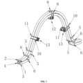
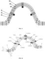
- a first flow tube 1, a second flow tube 2, a third flow tube 3 and a fourth flow tube 4 are all bent tubes, which are symmetrical in left and right, and are approximately V-shaped.
- the first flow tube 1 and the second flow tube 2 are both composed of multiple circular arc segments and multiple straight segments, have the same diameter, wall thickness and trajectory, are made of the same material, and are connected together by two first node plates 5 and two second node plates 6, so as to form a first flow tube pair.
- a measurement area of the pair of flow tubes is defined between the two first node plates 5, and an area outside this measurement area, including two second node plates 6, is a connecting area.
- the third flow tube 3 and the fourth flow tube 4 are both composed of multiple circular arc segments and multiple straight segments, have the same diameter, wall thickness and trajectory, are made of the same material, and are connected together by two first node plates 5 and two second node plates 6, so as to form a second flow tube pair.
- a measurement area of the pair of flows tubes is defined between the two first node plates 5, and an area outside this measurement area, including two second node plates 6, is a connecting area.
- the third flow tube 3 and the fourth flow tube 4 are located in an area enclosed by the first flow tube 1 and the second flow tube 2.
- the circular arc segments c1 and c2 of the flow tube do not need to be concentric.
- the first flow tube 1 and the third flow tube 3 are connected by a first driver fixing plate 8 and two first detector fixing plates 10 to form a first flow tube group.
- the second flow tube 2 and the fourth flow tube 4 are connected by a second driver fixing plate 9 and two second detector fixing plates 11 to form a second flow tube group.
- the detector 13 is arranged on the detector fixing plate, the driver 12 is arranged on the driver fixing plate, and spacing between two flow tube groups is the same along the whole bending trajectory of the flow tube groups.
- the flow tube groups are fixedly connected to form a coupled structure, thus coupling the vibration of the upper flow tube and the lower flow tube together.
- the node plates of the upper pair of flow tubes and the lower pair of flow tubes are independent and do not connect the upper bent tube and the lower bent tube together.
- the first pair of flow tubes and the second pair of flow tubes have equal or similar stiffness in the measurement area.
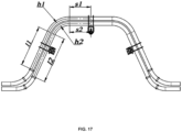
- the measurement area is symmetric in left and right, and the length of half the measurement area is composed of the straight tube segment (linear length l1 or l2) and a bent tube segment (circular arc length h1 or circular arc length h2), l1 and l2 are parallel, and h1 and h2 are concentric.
- the length of the measurement area of the first pair of flow tubes is equal to 2(l1+h1)
- the length of the measurement area of the second pair of flow tubes is equal to 2(!2+ h2).
- the optimal method is to calculate the stiffness of the measurement area of each pair of flow tubes more accurately using a finite element method, thus making the stiffness of the measurement areas of the flow tube pairs equal or similar.
- the first pair of flow tubes and the second pair of flow tubes each have independent node plates, and due to the independent node plates, an included angle a1 between the upper node plates and an included angle a2 between the lower node plates may have two design parameters to optimize vibration isolation, so as to minimize vibration transmission to the external parts. It can be found through the finite element simulation that the design of upper and lower sets of independent node plates can reduce the constraining force at the joint of flow tubes and a flow divider, thus improving the vibration isolation. This is also different from the previous design.
- the first pair of flow tubes and the second pair of flow tubes each have independent connecting circular arc segments c1 and c2.
- c1 and c2 are connecting areas outside the measurement area, the two circuit arc segments c1 and c2 are not connected together, and also do not need to be concentric, and the radius of the circular arc segments c1 and c2 may be larger or smaller, such that the flexibility of the design of the connecting area is increased, and the vibration isolation can be further improved.
- the driver fixing plate and the detector fixing plate are used to connect the flow tubes in the same group.
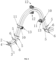
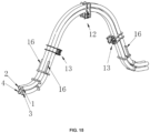
- This embodiment is an improvement on the basis of Embodiment 1, the coupling of the flow tubes in the same group may also be achieved by connecting the flow tubes in the same group only using the first driver fixing plate 8 and the second driver fixing plate 9, as shown in FIG. 3 and FIG. 4 .
- the advantage is that the structure of the detector can be relatively simple. As shown in FIG. 4 , there may also be two additional detectors, so there are four detectors in total.
- This embodiment is an improvement on the basis of Embodiment 1, the coupling of the flow tubes in the same group may also be achieved by connecting the flow tubes in the same group only using the first detector fixing plate 10 and the second detector fixing plate 11, as shown in FIG. 5 .
- the advantage of this scheme is that the structure of the driver may be relatively simple, or there may be two relatively independent drivers arranged up and down.
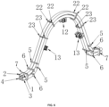
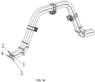
- the coupling of the flow tubes in the same group may also be achieved using a first fixing plate 22 and a second fixing plate 23 which are independent of each other, as shown in FIG.6 .
- the advantage of this scheme is that the structures of the driver and the detector may both be relatively simple, and the coupling of the flow tubes in the same group may be achieved using an independent fixing plate.
- This scheme also illustrates that a pair of third node plates 7 is added at the outermost of the connecting area, which is more conducive to the vibration isolation for large-caliber sensors.
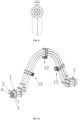
- the coupling of the flow tubes in the same group may also be achieved using the driver fixing plate or the detector fixing plate and an independent fixing plate, as shown in FIG. 7 , the flow tubes in the same group are connected by the first driver fixing plate 8, the second driver fixing plate 9 and the independent first fixing plate 22.
- This scheme also illustrates that a pair of third node plates 7 is added at the outermost of the connecting area, and all flow tubes are connected together by the third node plates 7 at the outermost layer, which is more conducive to the vibration isolation for large-caliber sensors.
- the flow tube with small aspect ratio is illustrated in this scheme, in order to determine the stiffness of the measurement area, the optimal method is to calculate more accurately using the finite element method. By adjusting design parameters, the stiffness of the measurement areas of the flow tube pairs is the same or similar.
- An overall appearance structure provided by the scheme of this embodiment is as shown in FIG. 8 and FIG. 9 .
- each group includes three flow tubes, and the three flow tubes in the same group are connected together by the fixing plate.
- the advantage of this scheme is that the measurement of larger flow can be achieved.
- This scheme also illustrates that a pair of third node plates 7 is added at the outermost of the connecting area, and all six flow tubes are connected together by the third node plates 7, which is more conducive to the vibration isolation for large-caliber sensors.
- the Coriolis flowmeter including six flow tubes may also be divided into four flow tube groups, in addition to the first flow tube group and the second flow tube group, the third flow tube group and the fourth flow tube group are provided.
- the first group has at least a first flow tube and a third flow tube
- the second group has at least a second flow tube and a fourth flow tube
- the third group may have at least one fifth flow tube 14
- the fourth group may have at least one sixth flow tube 15.
- the two flow tubes in the first group are connected together by an independent first fixing plate 22 and an independent second fixing plate 23 to form a group of flow tubes.
- the two flow tubes in the second group are connected together by the independent first fixing plate 22 and the independent second fixing plate 23 to form another group of flow tubes.
- the first group of flow tubes and the second group of flow tubes are vibrated at a first operating frequency generated by a first driver 1201, and the vibration is detected by two first detectors 1301.
- Each of the third group and the fourth group has one flow tube
- the vibration of the flow tubes is generated by a second driver 1202, and detected by a second detector 1302.
- the vibrations of the third group and the fourth group are at a second operating frequency, and the second operating frequency has a difference of at least 5 Hz from the first operating frequency.
- each group includes multiple flow tubes.
- the above schemes all use flow tubes with the same outer diameter and thickness.
- the lengths of the measurement areas need to be approximately equal.
- another design is given to illustrate the design principle of the present disclosure.
- the stiffness can be approximately equal through different thicknesses of the flow tubes.
- the length of the measurement area of the first pair of flow tubes is greater than that of the measurement area of the second pair of flow tubes, if similar stiffness is to be achieved, the thickness t1 of the first pair of flow tubes needs to be greater than the thickness t2 of the second pair of flow tubes.
- the stiffness can be enhanced by a reinforcing plate 16, such that the stiffness of a pair of flow tubes is increased to make stiffness of the two pairs of flow tubes similar to each other.
- the stiffness of the measurement area of the first pair of flow tubes is relatively small, the stiffness of the measurement area of the first pair of flow tubes can be increased by adding the reinforcing plate 16 in the measurement area, and thus the stiffness of the upper pair of flow tubes is similar to that of the lower pair of flow tubes.
- l1+ h1+s1 is the sum of the dimensions of a straight segment, a circular arc segment and another straight segment of the first flow tube;
- l2+h2+s2 is the sum of the dimensions of a straight segment, a circular arc segment and another straight segment of the second flow tube.
- orientation or positional relationship indicated by terms “center”, “top”, “bottom”, “left”, “right “, “vertical”, “horizontal”, “inside” and “outside” is based on the orientation or positional relationship shown in the drawings only for convenience of description of the present disclosure and simplification of description rather than indicating or implying that the device or element referred to must have a particular orientation, and be constructed and operated in a particular orientation, and thus are not to be construed as limiting the present disclosure.
- first and “second” are used for descriptive purposes only and are not to be construed as indicating or implying relative importance.
Landscapes
- Physics & Mathematics (AREA)
- General Physics & Mathematics (AREA)
- Fluid Mechanics (AREA)
- Health & Medical Sciences (AREA)
- Life Sciences & Earth Sciences (AREA)
- Chemical & Material Sciences (AREA)
- Analytical Chemistry (AREA)
- Biochemistry (AREA)
- General Health & Medical Sciences (AREA)
- Immunology (AREA)
- Pathology (AREA)
- Measuring Volume Flow (AREA)
Applications Claiming Priority (2)
| Application Number | Priority Date | Filing Date | Title |
|---|---|---|---|
| CN202211552633.4A CN115560815B (zh) | 2022-12-06 | 2022-12-06 | 一种多流量管科氏流量计 |
| PCT/CN2023/080963 WO2024119647A1 (zh) | 2022-12-06 | 2023-03-13 | 一种多流量管科氏流量计 |
Publications (2)
| Publication Number | Publication Date |
|---|---|
| EP4403884A1 true EP4403884A1 (de) | 2024-07-24 |
| EP4403884A4 EP4403884A4 (de) | 2024-12-04 |
Family
ID=91335176
Family Applications (1)
| Application Number | Title | Priority Date | Filing Date |
|---|---|---|---|
| EP23866657.2A Pending EP4403884A4 (de) | 2022-12-06 | 2023-03-13 | Coriolis-durchflussmesser mit mehreren strömungsrohren |
Country Status (3)
| Country | Link |
|---|---|
| US (1) | US12287230B2 (de) |
| EP (1) | EP4403884A4 (de) |
| CA (1) | CA3234921C (de) |
Family Cites Families (16)
| Publication number | Priority date | Publication date | Assignee | Title |
|---|---|---|---|---|
| US7127952B2 (en) * | 2004-07-23 | 2006-10-31 | Endress + Hauser Flowtec Ag | Vibration-type measurement pickup for measuring media flowing in two medium-lines, and inline measuring device having such a pickup |
| WO2011085851A1 (de) | 2009-12-21 | 2011-07-21 | Endress+Hauser Flowtec Ag | Messaufnehmer vom vibrationstyp |
| DE102011013263B4 (de) * | 2011-03-07 | 2018-02-15 | Krohne Ag | Coriolis-Massedurchflussmessgerät |
| CN103884395A (zh) | 2012-12-21 | 2014-06-25 | 上海一诺仪表有限公司 | 八流道型科里奥利质量流量计传感器 |
| CN103900652A (zh) | 2012-12-28 | 2014-07-02 | 上海一诺仪表有限公司 | 多流道型科里奥利质量流量计传感器流体主件 |
| US10209112B2 (en) | 2014-04-07 | 2019-02-19 | Micro Motion, Inc. | Apparatus and method for detecting asymmetric flow in vibrating flowmeters |
| CN104101394A (zh) | 2014-07-31 | 2014-10-15 | 北京天辰博锐科技有限公司 | 科氏质量流量传感器 |
| CN104406645A (zh) | 2014-11-07 | 2015-03-11 | 孙晓君 | 一种质量流量传感器 |
| DE102015104931A1 (de) | 2014-12-31 | 2016-06-30 | Endress + Hauser Flowtec Ag | Coriolis-Massedurchfussmessgerät mit vier gebogenen Messrohren |
| CN204854846U (zh) | 2015-05-13 | 2015-12-09 | 厦门均溪自控有限公司 | 一种防堵塞的科里奥利质量流量计 |
| DE102016125615A1 (de) * | 2016-12-23 | 2018-06-28 | Endress + Hauser Flowtec Ag | Messaufnehmer vom Vibrationstyp zum Messen der Dichte und/oder des Massedurchflusses eines Mediums |
| CN206891504U (zh) | 2017-06-28 | 2018-01-16 | 郭华 | 微弯型列管式质量流量计 |
| DE102018133318A1 (de) * | 2018-12-21 | 2020-06-25 | Endress+Hauser Flowtec Ag | Vibronisches Meßsystem |
| DE102019114330A1 (de) | 2019-05-28 | 2020-12-03 | Endress+Hauser Flowtec Ag | Meßwandler vom Vibrationstyp sowie damit gebildetes vibronisches Meßsystem |
| CN112857494A (zh) | 2021-01-21 | 2021-05-28 | 沃森测控技术(河北)有限公司 | 一种弯管型科氏流量计节点板 |
| CN115560815B (zh) | 2022-12-06 | 2023-04-07 | 沃森测控技术(河北)有限公司 | 一种多流量管科氏流量计 |
-
2023
- 2023-03-13 EP EP23866657.2A patent/EP4403884A4/de active Pending
- 2023-03-13 US US18/723,080 patent/US12287230B2/en active Active
- 2023-03-13 CA CA3234921A patent/CA3234921C/en active Active
Also Published As
| Publication number | Publication date |
|---|---|
| CA3234921A1 (en) | 2024-06-06 |
| CA3234921C (en) | 2025-06-10 |
| US12287230B2 (en) | 2025-04-29 |
| US20250060236A1 (en) | 2025-02-20 |
| EP4403884A4 (de) | 2024-12-04 |
Similar Documents
| Publication | Publication Date | Title |
|---|---|---|
| CN101858765B (zh) | 类直管型科里奥利质量流量计 | |
| CN115560815B (zh) | 一种多流量管科氏流量计 | |
| US20150323362A1 (en) | Mass flowmeter | |
| CN111272240A (zh) | 一种内置式斜反射多声道超声波流量测量模块及流量计 | |
| CN210570866U (zh) | 一种u型质量流量计 | |
| EP4403884A1 (de) | Coriolis-durchflussmesser mit mehreren strömungsrohren | |
| US20210164822A1 (en) | Coriolis measuring sensor and coriolis measuring device | |
| CN218822555U (zh) | 一种对射式气体流量测量仪表流道组件及流量测量仪表 | |
| WO2016141628A1 (zh) | 一种质量流量传感器 | |
| CA2552867C (en) | Coriolis flowmeter | |
| CN110388967A (zh) | U型科氏质量流量计的分流体及u型科氏质量流量计 | |
| RU2839672C2 (ru) | Расходомер кориолиса с множеством расходомерных трубок | |
| CN117848437A (zh) | 流量传感器及科氏流量计 | |
| CN204594515U (zh) | 一种质量流量传感器 | |
| CN111964739A (zh) | 一种气流超声波流量计流道结构 | |
| CN208606830U (zh) | 一种直管型科里奥利质量流量计 | |
| CN211717528U (zh) | 一种内置式斜反射多声道超声波流量测量模块及流量计 | |
| JP4485648B2 (ja) | 超音波流量計 | |
| CN211576268U (zh) | 用于质量流量计的缓冲分流器、质量流量计和测量系统 | |
| CN211452465U (zh) | 超声波流量计和流体管路 | |
| JP2000065613A (ja) | 超音波流量計 | |
| JP2939242B1 (ja) | コリオリ質量流量計 | |
| JPH0499918A (ja) | 質量流量計 | |
| CN213301351U (zh) | 一种多声道超声波气体流量计 | |
| WO2025156236A1 (zh) | 一种流量计及流量测量管 |
Legal Events
| Date | Code | Title | Description |
|---|---|---|---|
| STAA | Information on the status of an ep patent application or granted ep patent |
Free format text: STATUS: UNKNOWN |
|
| STAA | Information on the status of an ep patent application or granted ep patent |
Free format text: STATUS: THE INTERNATIONAL PUBLICATION HAS BEEN MADE |
|
| PUAI | Public reference made under article 153(3) epc to a published international application that has entered the european phase |
Free format text: ORIGINAL CODE: 0009012 |
|
| STAA | Information on the status of an ep patent application or granted ep patent |
Free format text: STATUS: REQUEST FOR EXAMINATION WAS MADE |
|
| 17P | Request for examination filed |
Effective date: 20240328 |
|
| AK | Designated contracting states |
Kind code of ref document: A1 Designated state(s): AL AT BE BG CH CY CZ DE DK EE ES FI FR GB GR HR HU IE IS IT LI LT LU LV MC ME MK MT NL NO PL PT RO RS SE SI SK SM TR |
|
| A4 | Supplementary search report drawn up and despatched |
Effective date: 20241031 |
|
| RIC1 | Information provided on ipc code assigned before grant |
Ipc: G01N 9/00 20060101ALN20241025BHEP Ipc: G01F 1/84 20060101AFI20241025BHEP |
|
| STAA | Information on the status of an ep patent application or granted ep patent |
Free format text: STATUS: EXAMINATION IS IN PROGRESS |
|
| 17Q | First examination report despatched |
Effective date: 20250626 |