EP4403832B1 - Cooktop unit with integrated extractor hood - Google Patents
Cooktop unit with integrated extractor hood Download PDFInfo
- Publication number
- EP4403832B1 EP4403832B1 EP24152215.0A EP24152215A EP4403832B1 EP 4403832 B1 EP4403832 B1 EP 4403832B1 EP 24152215 A EP24152215 A EP 24152215A EP 4403832 B1 EP4403832 B1 EP 4403832B1
- Authority
- EP
- European Patent Office
- Prior art keywords
- filtering element
- unit
- spacer
- filter
- filtering
- Prior art date
- Legal status (The legal status is an assumption and is not a legal conclusion. Google has not performed a legal analysis and makes no representation as to the accuracy of the status listed.)
- Active
Links
Images


Classifications
-
- F—MECHANICAL ENGINEERING; LIGHTING; HEATING; WEAPONS; BLASTING
- F24—HEATING; RANGES; VENTILATING
- F24C—DOMESTIC STOVES OR RANGES ; DETAILS OF DOMESTIC STOVES OR RANGES, OF GENERAL APPLICATION
- F24C15/00—Details
- F24C15/20—Removing cooking fumes
- F24C15/2042—Devices for removing cooking fumes structurally associated with a cooking range e.g. downdraft
Definitions
- the present invention relates to a cooktop unit with an integrated extraction hood.
- Extractor hoods integrated into a cooktop for kitchens are known.
- Such types of extractor hoods comprise an extraction system arranged under the cooktop in communication with an opening of the cooktop, in such a way that the fumes generated when cooking foods are extracted downwardly through the opening of the cooktop.
- a filter generally comprising a plurality of mesh-shaped filtering elements, is arranged in the opening of the cooktop, said filter being suitable for extracting the air, filtering the fats contained in the extracted fumes, and preventing the passage of solid particles with a larger diameter than the holes of the meshes of the filtering element.
- Prior art documents describing similar extractor hoods integrated into a cooktop include US2014/230662 A1 , US2014/182575 A1 , EP3951267 A1 , CN105203602 B , EP3492818 A1 and EP3951270 A1 .
- a drawback of such types of extractor hoods integrated in the cooktop consists in the fact that liquids may fall onto the cooktop frequently during the operation of the cooktop and of the extractor hood.
- the unit (100) comprises a cooktop (1) and an extractor hood (2) integrated into the cooktop (1).
- the cooktop (1) comprises stoves (10), such as induction stoves.
- An extraction opening (11) is obtained in the cooktop (1).
- the extraction opening (11) communicates with a housing (20) disposed under the cooktop (1).
- An extraction system (21) of the extraction hood is arranged in the housing (20), it being suitable for extracting the air from the extraction opening (11) downwardly.
- the extraction system (21) comprises a fan (22) and an electric motor (23) that operates the fan.
- a filter (3) is arranged in the extraction opening (11).
- the filter (3) must be suitable for letting the air extracted by the extraction system (21) pass through and at the same time retain the fats contained in the fumes extracted by the extractor hood and the solid particles with a given diameter.
- the filter (3) is removably mounted in the extraction opening (11) in such a way that it can be removed, cleaned and/or replaced.
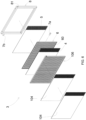
- the filter (3) comprises:
- the first filtering element (4) and the second filtering element (5) operate as two electrical contacts of a normally open switch or as two armatures of a capacitor, in which the spacer (6) operates as dielectric between the armatures of the capacitor.
- the filter (3) may also comprise a frame (8) in the form of a perimeter frame that retains and supports the filtering elements (4, 5) and the spacer (6) in package configuration.
- the frame (8) may be made of an insulating material in such a way not to create an electrical bridge between the first filtering element (4) and the second filtering element (5).
- the frame (8) has two holes (80) that are crossed by the shanks (61) of the spacer, so that the pins (7a, 7b) protrude externally from the frame.
- the two pins (7a, 7b) of the filter (3) are electrically connected to detection means (9) suitable for detecting an electrical connection between the first filtering element (4) and the second filtering element (5).
- the detection means (9) are connected to control means (91) configured to send a control signal (S) to the electric motor (23) of the extractor hood in order to stop it when the detection means detect an electrical connection between the first filtering element (4) and the second filtering element (5).
- the filter (7) operates as a normally open switch that is closed when water passes through the spacer (6) establishing an electrical connection between the first filtering element (4) and the second filtering element (5).
- the detection means (9) comprise a capacitive detector (90) suitable for detecting a capacity (C) of the capacitor generated by the spacer (6) arranged between the first filtering element (4) and the second filtering element (5).
- the control device (91) comprises a comparator (92) configured to compare the detected capacity (C) with a preset capacity threshold value (C1). When the detected capacity (C) exceeds the capacity threshold value (C1), the control device (91) sends a control signal (S) to the electric motor (23) of the extractor hood in order to stop it, thus preventing the extraction system (21) of the extractor hood from extracting the water.
- the detection means (9) may comprise an electrical conductivity detector suitable for detecting the electrical conductivity between the first filtering element (4) and the second filtering element (5).
- the detected electrical conductivity is very low because the spacer (6) operates as insulator between the first filtering element (4) and the second filtering element (5). If the water passes through the spacer (6), the electrical conductivity increases significantly, as the water operates as electrical conductor.
- the control device (91) sends a control signal (S) to the electric motor (23) of the extractor hood in order to stop it, thus preventing the extraction system (21) of the extractor hood from extracting the water.
- a second embodiment of the filter (3) is illustrated, in which at least a third filtering element (104) is added in front of the first filtering element.
- the third filtering element (104) consists of a mesh substantially similar to that of the first filtering element (4) and of the second filtering element (5). Two overlapping third filtering elements (104) are shown in Fig. 2 .
- the third filtering element (104) is isolated from the first filtering element (4) by means of a second spacer (106) substantially similar to the first spacer.
- the frame (8) is made of a conductive material
- the first filtering element (4) is isolated from the frame (8)
- the second filtering element (5) is in contact with the frame (8). Therefore, the second pin (7b) is arranged in the frame (8).
- a third embodiment of the filter (3) is illustrated, in which at least a fourth filtering element (105) is added behind the second filtering element (5).
- the fourth filtering element (105) consists of a mesh substantially similar to that of the first filtering element (4) and of the second filtering element (5).
- a third filtering element (104) arranged in front of the first filtering element (4) and a fourth filtering element (105) arranged behind the second filtering element (5) are shown in Fig. 8 .
- the fourth filtering element (105) is isolated from the second filtering element (5) by means of a third spacer (206) substantially similar to the first spacer (6).
- the frame (8) is made of a conductive material
- the first filtering element (4) is isolated from the frame (8)
- the second filtering element (5) is isolated from the frame (8).
- the spacer (6) has a perimeter edge (60) with two shanks (61) that protrude from the perimeter edge (60) to penetrate respective holes (81) of the frame (8).
- the shanks (61) have holes (62) into which the pins (7a, 7b) are press-fitted so that the pins (7a, 7b) protrude from the frame (8) in order to be connected to electrical cables.
- Tests were performed on the filter (3) for the purpose of detecting an accidental fall of hot or cold water from the cooktop (1) into the extraction opening (11) so as to stop the electric motor (23) and at the same time ensure a normal steam extraction when the hot water contained in a pot placed on a stove starts boiling.
- the passage of saturated or unsaturated steam through the filter (3) must not be detected by the detection device (90) in such a way that the extractor hood (2) may be operated normally.
- Tests were carried out with the filter (3) in clean conditions and after soiling the filter with an emulsion of water and oil: 20 g of oil in 100 g of water, letting the water evaporate in an oven at 50°C for 8 hours.
- the capacity values (C) measured in these tests remained unchanged.
- Another test was carried out by placing three pots with a total of 1.5 liters of water on three stoves (10) of the cooktop, in order to simulate the extraction of a sufficient quantity of steam.
- the extractor hood (2) was set at the maximum extraction speed.
- the formation of condensation on the filter (3) was monitored and a proper operation of the detection device (90) was verified, said detection device (90) being calibrated in such a way that the detected capacity (C) did not exceed the capacity threshold value (C1) with the accumulation of steam on the surfaces of the filter (3).
Landscapes
- Engineering & Computer Science (AREA)
- Chemical & Material Sciences (AREA)
- Combustion & Propulsion (AREA)
- Mechanical Engineering (AREA)
- General Engineering & Computer Science (AREA)
- Ventilation (AREA)
Applications Claiming Priority (1)
| Application Number | Priority Date | Filing Date | Title |
|---|---|---|---|
| IT102023000000822A IT202300000822A1 (it) | 2023-01-20 | 2023-01-20 | Gruppo piano cottura con cappa integrata. |
Publications (3)
| Publication Number | Publication Date |
|---|---|
| EP4403832A1 EP4403832A1 (en) | 2024-07-24 |
| EP4403832C0 EP4403832C0 (en) | 2025-06-25 |
| EP4403832B1 true EP4403832B1 (en) | 2025-06-25 |
Family
ID=86099984
Family Applications (1)
| Application Number | Title | Priority Date | Filing Date |
|---|---|---|---|
| EP24152215.0A Active EP4403832B1 (en) | 2023-01-20 | 2024-01-16 | Cooktop unit with integrated extractor hood |
Country Status (4)
| Country | Link |
|---|---|
| EP (1) | EP4403832B1 (pl) |
| ES (1) | ES3042543T3 (pl) |
| IT (1) | IT202300000822A1 (pl) |
| PL (1) | PL4403832T3 (pl) |
Family Cites Families (6)
| Publication number | Priority date | Publication date | Assignee | Title |
|---|---|---|---|---|
| US20080274683A1 (en) * | 2007-05-04 | 2008-11-06 | Current Energy Controls, Lp | Autonomous Ventilation System |
| US9677772B2 (en) * | 2013-02-21 | 2017-06-13 | Rain Mountain, Llc | Intelligent ventilating safety range hood control system |
| CN105203602B (zh) * | 2015-10-15 | 2018-05-01 | 广东美的厨房电器制造有限公司 | 油烟机及其油污程度检测装置和方法 |
| EP3492818A1 (en) * | 2017-11-30 | 2019-06-05 | Vestel Elektronik Sanayi ve Ticaret A.S. | Detection system and detection method |
| EP3951270A1 (en) * | 2020-08-05 | 2022-02-09 | Electrolux Appliances Aktiebolag | Combination appliance |
| EP3951267A1 (en) * | 2020-08-05 | 2022-02-09 | Electrolux Appliances Aktiebolag | Combination appliance and the use of the combination appliance |
-
2023
- 2023-01-20 IT IT102023000000822A patent/IT202300000822A1/it unknown
-
2024
- 2024-01-16 EP EP24152215.0A patent/EP4403832B1/en active Active
- 2024-01-16 ES ES24152215T patent/ES3042543T3/es active Active
- 2024-01-16 PL PL24152215.0T patent/PL4403832T3/pl unknown
Also Published As
| Publication number | Publication date |
|---|---|
| PL4403832T3 (pl) | 2025-11-03 |
| EP4403832C0 (en) | 2025-06-25 |
| IT202300000822A1 (it) | 2024-07-20 |
| EP4403832A1 (en) | 2024-07-24 |
| ES3042543T3 (en) | 2025-11-21 |
Similar Documents
| Publication | Publication Date | Title |
|---|---|---|
| US9289090B2 (en) | Cooktop appliances with intelligent response to cooktop audio | |
| US20150033952A1 (en) | Smoke exhaust system for a cooking appliance | |
| JP2019510955A (ja) | 一体化フードを持つ調理用レンジ | |
| EP0762059A2 (de) | Elektrische Sicherheitsvorrichtung für Küchenherde oder Kochstelle und Verfahren zum Betrieb eines Küchenherde oder einer Kochstelle | |
| EP4403832B1 (en) | Cooktop unit with integrated extractor hood | |
| US4687908A (en) | Convection blower for conventional electric ovens | |
| DE10307247A1 (de) | Einrichtung zum Absaugen von Abluft eines Elektrowärmegeräts und Verfahren zum Betrieb derselben | |
| CN205018816U (zh) | 食物电加工器具 | |
| CN110966631A (zh) | 安全检测方法、装置、油烟机和介质 | |
| US4254325A (en) | Electric oven toaster construction | |
| CN211299602U (zh) | 一种电烤炉 | |
| CN108139081B (zh) | 家用器具加热装置 | |
| WO2012152692A1 (en) | An oven wherein presence of tray is detected in the cooking cavity | |
| US20210251426A1 (en) | Filter pan detection and fluid sensor system | |
| NL1015566C2 (nl) | Voeding voor elektrische huishoudelijke apparatuur en huishoudelijk apparaat, voor samenwerking met een dergelijke voeding. | |
| DE10101736A1 (de) | Verfahren und Vorrichtung zum Betrieb einer steuer- bzw. regelbaren Dunstabzugshaube | |
| CN212611558U (zh) | 一种干衣机 | |
| CN112869581B (zh) | 烹饪器具和烹饪器具的控制方法 | |
| KR102610539B1 (ko) | 후드가 장착된 부침기 | |
| EP0363329B1 (en) | Conveyor unit for hoods with manual and automatic ionic filter | |
| WO2015144615A1 (en) | Kitchen hood with anti-condensation device | |
| CN214414679U (zh) | 一种无烟烤盘的水盘装配结构 | |
| CN211432333U (zh) | 烹饪锅具以及烹调器 | |
| CN209673958U (zh) | 检测压力开关的电路以及烹饪器具 | |
| JPH04169727A (ja) | 排煙装置 |
Legal Events
| Date | Code | Title | Description |
|---|---|---|---|
| PUAI | Public reference made under article 153(3) epc to a published international application that has entered the european phase |
Free format text: ORIGINAL CODE: 0009012 |
|
| STAA | Information on the status of an ep patent application or granted ep patent |
Free format text: STATUS: THE APPLICATION HAS BEEN PUBLISHED |
|
| AK | Designated contracting states |
Kind code of ref document: A1 Designated state(s): AL AT BE BG CH CY CZ DE DK EE ES FI FR GB GR HR HU IE IS IT LI LT LU LV MC ME MK MT NL NO PL PT RO RS SE SI SK SM TR |
|
| STAA | Information on the status of an ep patent application or granted ep patent |
Free format text: STATUS: REQUEST FOR EXAMINATION WAS MADE |
|
| 17P | Request for examination filed |
Effective date: 20250110 |
|
| GRAP | Despatch of communication of intention to grant a patent |
Free format text: ORIGINAL CODE: EPIDOSNIGR1 |
|
| STAA | Information on the status of an ep patent application or granted ep patent |
Free format text: STATUS: GRANT OF PATENT IS INTENDED |
|
| INTG | Intention to grant announced |
Effective date: 20250221 |
|
| GRAS | Grant fee paid |
Free format text: ORIGINAL CODE: EPIDOSNIGR3 |
|
| GRAA | (expected) grant |
Free format text: ORIGINAL CODE: 0009210 |
|
| STAA | Information on the status of an ep patent application or granted ep patent |
Free format text: STATUS: THE PATENT HAS BEEN GRANTED |
|
| RAP3 | Party data changed (applicant data changed or rights of an application transferred) |
Owner name: SIFIM - S.R.L. |
|
| AK | Designated contracting states |
Kind code of ref document: B1 Designated state(s): AL AT BE BG CH CY CZ DE DK EE ES FI FR GB GR HR HU IE IS IT LI LT LU LV MC ME MK MT NL NO PL PT RO RS SE SI SK SM TR |
|
| REG | Reference to a national code |
Ref country code: GB Ref legal event code: FG4D |
|
| REG | Reference to a national code |
Ref country code: CH Ref legal event code: EP |
|
| REG | Reference to a national code |
Ref country code: CH Ref legal event code: EP |
|
| REG | Reference to a national code |
Ref country code: IE Ref legal event code: FG4D |
|
| REG | Reference to a national code |
Ref country code: DE Ref legal event code: R096 Ref document number: 602024000220 Country of ref document: DE |
|
| U01 | Request for unitary effect filed |
Effective date: 20250723 |
|
| U07 | Unitary effect registered |
Designated state(s): AT BE BG DE DK EE FI FR IT LT LU LV MT NL PT RO SE SI Effective date: 20250730 |
|
| PG25 | Lapsed in a contracting state [announced via postgrant information from national office to epo] |
Ref country code: NO Free format text: LAPSE BECAUSE OF FAILURE TO SUBMIT A TRANSLATION OF THE DESCRIPTION OR TO PAY THE FEE WITHIN THE PRESCRIBED TIME-LIMIT Effective date: 20250925 Ref country code: GR Free format text: LAPSE BECAUSE OF FAILURE TO SUBMIT A TRANSLATION OF THE DESCRIPTION OR TO PAY THE FEE WITHIN THE PRESCRIBED TIME-LIMIT Effective date: 20250926 |
|
| PG25 | Lapsed in a contracting state [announced via postgrant information from national office to epo] |
Ref country code: HR Free format text: LAPSE BECAUSE OF FAILURE TO SUBMIT A TRANSLATION OF THE DESCRIPTION OR TO PAY THE FEE WITHIN THE PRESCRIBED TIME-LIMIT Effective date: 20250625 |
|
| PG25 | Lapsed in a contracting state [announced via postgrant information from national office to epo] |
Ref country code: RS Free format text: LAPSE BECAUSE OF FAILURE TO SUBMIT A TRANSLATION OF THE DESCRIPTION OR TO PAY THE FEE WITHIN THE PRESCRIBED TIME-LIMIT Effective date: 20250925 |
|
| REG | Reference to a national code |
Ref country code: ES Ref legal event code: FG2A Ref document number: 3042543 Country of ref document: ES Kind code of ref document: T3 Effective date: 20251121 |
|
| PG25 | Lapsed in a contracting state [announced via postgrant information from national office to epo] |
Ref country code: IS Free format text: LAPSE BECAUSE OF FAILURE TO SUBMIT A TRANSLATION OF THE DESCRIPTION OR TO PAY THE FEE WITHIN THE PRESCRIBED TIME-LIMIT Effective date: 20251025 |
|
| PG25 | Lapsed in a contracting state [announced via postgrant information from national office to epo] |
Ref country code: SM Free format text: LAPSE BECAUSE OF FAILURE TO SUBMIT A TRANSLATION OF THE DESCRIPTION OR TO PAY THE FEE WITHIN THE PRESCRIBED TIME-LIMIT Effective date: 20250625 |
|
| PG25 | Lapsed in a contracting state [announced via postgrant information from national office to epo] |
Ref country code: CZ Free format text: LAPSE BECAUSE OF FAILURE TO SUBMIT A TRANSLATION OF THE DESCRIPTION OR TO PAY THE FEE WITHIN THE PRESCRIBED TIME-LIMIT Effective date: 20250625 |
|
| PG25 | Lapsed in a contracting state [announced via postgrant information from national office to epo] |
Ref country code: SK Free format text: LAPSE BECAUSE OF FAILURE TO SUBMIT A TRANSLATION OF THE DESCRIPTION OR TO PAY THE FEE WITHIN THE PRESCRIBED TIME-LIMIT Effective date: 20250625 |
|
| U20 | Renewal fee for the european patent with unitary effect paid |
Year of fee payment: 3 Effective date: 20260107 |