EP4403804B1 - Drehschieberventil - Google Patents
Drehschieberventil Download PDFInfo
- Publication number
- EP4403804B1 EP4403804B1 EP24151854.7A EP24151854A EP4403804B1 EP 4403804 B1 EP4403804 B1 EP 4403804B1 EP 24151854 A EP24151854 A EP 24151854A EP 4403804 B1 EP4403804 B1 EP 4403804B1
- Authority
- EP
- European Patent Office
- Prior art keywords
- valve
- rotary disc
- disc
- assembly
- rotary
- Prior art date
- Legal status (The legal status is an assumption and is not a legal conclusion. Google has not performed a legal analysis and makes no representation as to the accuracy of the status listed.)
- Active
Links
Images











Classifications
-
- F—MECHANICAL ENGINEERING; LIGHTING; HEATING; WEAPONS; BLASTING
- F16—ENGINEERING ELEMENTS AND UNITS; GENERAL MEASURES FOR PRODUCING AND MAINTAINING EFFECTIVE FUNCTIONING OF MACHINES OR INSTALLATIONS; THERMAL INSULATION IN GENERAL
- F16K—VALVES; TAPS; COCKS; ACTUATING-FLOATS; DEVICES FOR VENTING OR AERATING
- F16K3/00—Gate valves or sliding valves, i.e. cut-off apparatus with closing members having a sliding movement along the seat for opening and closing
- F16K3/02—Gate valves or sliding valves, i.e. cut-off apparatus with closing members having a sliding movement along the seat for opening and closing with flat sealing faces; Packings therefor
- F16K3/04—Gate valves or sliding valves, i.e. cut-off apparatus with closing members having a sliding movement along the seat for opening and closing with flat sealing faces; Packings therefor with pivoted closure members
- F16K3/06—Gate valves or sliding valves, i.e. cut-off apparatus with closing members having a sliding movement along the seat for opening and closing with flat sealing faces; Packings therefor with pivoted closure members in the form of closure plates arranged between supply and discharge passages
- F16K3/08—Gate valves or sliding valves, i.e. cut-off apparatus with closing members having a sliding movement along the seat for opening and closing with flat sealing faces; Packings therefor with pivoted closure members in the form of closure plates arranged between supply and discharge passages with circular plates rotatable around their centres
-
- B—PERFORMING OPERATIONS; TRANSPORTING
- B64—AIRCRAFT; AVIATION; COSMONAUTICS
- B64B—LIGHTER-THAN AIR AIRCRAFT
- B64B1/00—Lighter-than-air aircraft
- B64B1/58—Arrangements or construction of gas-bags; Filling arrangements
- B64B1/64—Gas valve operating mechanisms
-
- F—MECHANICAL ENGINEERING; LIGHTING; HEATING; WEAPONS; BLASTING
- F16—ENGINEERING ELEMENTS AND UNITS; GENERAL MEASURES FOR PRODUCING AND MAINTAINING EFFECTIVE FUNCTIONING OF MACHINES OR INSTALLATIONS; THERMAL INSULATION IN GENERAL
- F16K—VALVES; TAPS; COCKS; ACTUATING-FLOATS; DEVICES FOR VENTING OR AERATING
- F16K3/00—Gate valves or sliding valves, i.e. cut-off apparatus with closing members having a sliding movement along the seat for opening and closing
- F16K3/02—Gate valves or sliding valves, i.e. cut-off apparatus with closing members having a sliding movement along the seat for opening and closing with flat sealing faces; Packings therefor
- F16K3/0254—Gate valves or sliding valves, i.e. cut-off apparatus with closing members having a sliding movement along the seat for opening and closing with flat sealing faces; Packings therefor being operated by particular means
-
- F—MECHANICAL ENGINEERING; LIGHTING; HEATING; WEAPONS; BLASTING
- F16—ENGINEERING ELEMENTS AND UNITS; GENERAL MEASURES FOR PRODUCING AND MAINTAINING EFFECTIVE FUNCTIONING OF MACHINES OR INSTALLATIONS; THERMAL INSULATION IN GENERAL
- F16K—VALVES; TAPS; COCKS; ACTUATING-FLOATS; DEVICES FOR VENTING OR AERATING
- F16K3/00—Gate valves or sliding valves, i.e. cut-off apparatus with closing members having a sliding movement along the seat for opening and closing
- F16K3/02—Gate valves or sliding valves, i.e. cut-off apparatus with closing members having a sliding movement along the seat for opening and closing with flat sealing faces; Packings therefor
- F16K3/04—Gate valves or sliding valves, i.e. cut-off apparatus with closing members having a sliding movement along the seat for opening and closing with flat sealing faces; Packings therefor with pivoted closure members
- F16K3/06—Gate valves or sliding valves, i.e. cut-off apparatus with closing members having a sliding movement along the seat for opening and closing with flat sealing faces; Packings therefor with pivoted closure members in the form of closure plates arranged between supply and discharge passages
- F16K3/08—Gate valves or sliding valves, i.e. cut-off apparatus with closing members having a sliding movement along the seat for opening and closing with flat sealing faces; Packings therefor with pivoted closure members in the form of closure plates arranged between supply and discharge passages with circular plates rotatable around their centres
- F16K3/085—Gate valves or sliding valves, i.e. cut-off apparatus with closing members having a sliding movement along the seat for opening and closing with flat sealing faces; Packings therefor with pivoted closure members in the form of closure plates arranged between supply and discharge passages with circular plates rotatable around their centres the axis of supply passage and the axis of discharge passage being coaxial and parallel to the axis of rotation of the plates
-
- F—MECHANICAL ENGINEERING; LIGHTING; HEATING; WEAPONS; BLASTING
- F16—ENGINEERING ELEMENTS AND UNITS; GENERAL MEASURES FOR PRODUCING AND MAINTAINING EFFECTIVE FUNCTIONING OF MACHINES OR INSTALLATIONS; THERMAL INSULATION IN GENERAL
- F16K—VALVES; TAPS; COCKS; ACTUATING-FLOATS; DEVICES FOR VENTING OR AERATING
- F16K3/00—Gate valves or sliding valves, i.e. cut-off apparatus with closing members having a sliding movement along the seat for opening and closing
- F16K3/02—Gate valves or sliding valves, i.e. cut-off apparatus with closing members having a sliding movement along the seat for opening and closing with flat sealing faces; Packings therefor
- F16K3/04—Gate valves or sliding valves, i.e. cut-off apparatus with closing members having a sliding movement along the seat for opening and closing with flat sealing faces; Packings therefor with pivoted closure members
- F16K3/10—Gate valves or sliding valves, i.e. cut-off apparatus with closing members having a sliding movement along the seat for opening and closing with flat sealing faces; Packings therefor with pivoted closure members with special arrangements for separating the sealing faces or for pressing them together
-
- F—MECHANICAL ENGINEERING; LIGHTING; HEATING; WEAPONS; BLASTING
- F16—ENGINEERING ELEMENTS AND UNITS; GENERAL MEASURES FOR PRODUCING AND MAINTAINING EFFECTIVE FUNCTIONING OF MACHINES OR INSTALLATIONS; THERMAL INSULATION IN GENERAL
- F16K—VALVES; TAPS; COCKS; ACTUATING-FLOATS; DEVICES FOR VENTING OR AERATING
- F16K3/00—Gate valves or sliding valves, i.e. cut-off apparatus with closing members having a sliding movement along the seat for opening and closing
- F16K3/30—Details
- F16K3/316—Guiding of the slide
-
- F—MECHANICAL ENGINEERING; LIGHTING; HEATING; WEAPONS; BLASTING
- F16—ENGINEERING ELEMENTS AND UNITS; GENERAL MEASURES FOR PRODUCING AND MAINTAINING EFFECTIVE FUNCTIONING OF MACHINES OR INSTALLATIONS; THERMAL INSULATION IN GENERAL
- F16K—VALVES; TAPS; COCKS; ACTUATING-FLOATS; DEVICES FOR VENTING OR AERATING
- F16K31/00—Actuating devices; Operating means; Releasing devices
- F16K31/44—Mechanical actuating means
- F16K31/52—Mechanical actuating means with crank, eccentric, or cam
- F16K31/524—Mechanical actuating means with crank, eccentric, or cam with a cam
- F16K31/52475—Mechanical actuating means with crank, eccentric, or cam with a cam comprising a sliding valve
-
- F—MECHANICAL ENGINEERING; LIGHTING; HEATING; WEAPONS; BLASTING
- F16—ENGINEERING ELEMENTS AND UNITS; GENERAL MEASURES FOR PRODUCING AND MAINTAINING EFFECTIVE FUNCTIONING OF MACHINES OR INSTALLATIONS; THERMAL INSULATION IN GENERAL
- F16K—VALVES; TAPS; COCKS; ACTUATING-FLOATS; DEVICES FOR VENTING OR AERATING
- F16K31/00—Actuating devices; Operating means; Releasing devices
- F16K31/44—Mechanical actuating means
- F16K31/52—Mechanical actuating means with crank, eccentric, or cam
- F16K31/528—Mechanical actuating means with crank, eccentric, or cam with pin and slot
- F16K31/5282—Mechanical actuating means with crank, eccentric, or cam with pin and slot comprising a pivoted disc or flap
-
- F—MECHANICAL ENGINEERING; LIGHTING; HEATING; WEAPONS; BLASTING
- F16—ENGINEERING ELEMENTS AND UNITS; GENERAL MEASURES FOR PRODUCING AND MAINTAINING EFFECTIVE FUNCTIONING OF MACHINES OR INSTALLATIONS; THERMAL INSULATION IN GENERAL
- F16K—VALVES; TAPS; COCKS; ACTUATING-FLOATS; DEVICES FOR VENTING OR AERATING
- F16K31/00—Actuating devices; Operating means; Releasing devices
- F16K31/44—Mechanical actuating means
- F16K31/52—Mechanical actuating means with crank, eccentric, or cam
- F16K31/528—Mechanical actuating means with crank, eccentric, or cam with pin and slot
- F16K31/5286—Mechanical actuating means with crank, eccentric, or cam with pin and slot comprising a sliding valve
-
- F—MECHANICAL ENGINEERING; LIGHTING; HEATING; WEAPONS; BLASTING
- F16—ENGINEERING ELEMENTS AND UNITS; GENERAL MEASURES FOR PRODUCING AND MAINTAINING EFFECTIVE FUNCTIONING OF MACHINES OR INSTALLATIONS; THERMAL INSULATION IN GENERAL
- F16K—VALVES; TAPS; COCKS; ACTUATING-FLOATS; DEVICES FOR VENTING OR AERATING
- F16K31/00—Actuating devices; Operating means; Releasing devices
- F16K31/44—Mechanical actuating means
- F16K31/53—Mechanical actuating means with toothed gearing
- F16K31/535—Mechanical actuating means with toothed gearing for rotating valves
-
- B—PERFORMING OPERATIONS; TRANSPORTING
- B64—AIRCRAFT; AVIATION; COSMONAUTICS
- B64B—LIGHTER-THAN AIR AIRCRAFT
- B64B1/00—Lighter-than-air aircraft
- B64B1/58—Arrangements or construction of gas-bags; Filling arrangements
- B64B1/62—Controlling gas pressure, heating, cooling, or discharging gas
Definitions
- the present disclosure relates generally to rotary valves, and in particular to rotary valves for use in pressure relief applications.
- valve types are known and used in gas handling applications. Such valves include flap gate valves, butterfly valves, guillotine valves, ball valves, and the like. For applications in which the valves are used to relieve gas from a gas-containing structure, such as during pressure relief operations, these valve types suffer from a variety of disadvantages.
- outward facing flap valves can suffer from the disadvantage that the flap is subjected to the force of wind (which, for example, in high altitude applications can approach or exceed 100 km/h). In such cases the high wind forces can twist and/or damage the flap.
- Using an inwardly oriented flap in such applications would solve the problem of flap damage but would undesirably require a fluid passage diameter of three or more times larger than an outward facing flap valve.
- a large structure would be required to take up the overhang of the valve (assuming a translation of 200 mm or more), and the associated motor would be in the fluid flow path, which is not acceptable.
- a motor located away from the valve would involve a large overhang, which is also not acceptable.
- Such geometries also require a structure to withstand the operating forces, which increases the overall mass of the valve.
- WO02013/073039A1 discloses a conventional rotary disc valve but fails to disclose a guide assembly and a valve disc assembly as defined in claim 1.
- a rotary valve is disclosed for use in gas pressure relief applications.
- the rotary valve is used to relieve internal helium pressures in an airship in the case of an overpressure condition within the helium-containing structure of the airship.
- the rotary valve is a safety valve used to relieve the pressure differential between internal helium pressure and the external ambient pressure as the airship rises.
- a rotary valve in which frictional opening forces are eliminated during rotation of the valve.
- a rotary valve includes a rotary disc that is guided within the external valve support structure, and a docking ramp that causes an axial translation of the rotating disc to compress the rotary disc against a seal when the valve is in the closed position to ensure a gas-tight seal exists when the valve is in the closed position.
- the kinematics of the ramp allow the rotary disc to be axially displaced away the seal so that the disc can be rotated to the open configuration (and then back to the closed configuration) without engaging the seal, thus eliminating friction between the two during cycling of the valve.
- Rotation of the rotary disc is obtained by the action of a motor that, via a pinion and worm connection, engages teeth on an outside surface of the rotary disc assembly.
- Axial translation of the rotary disc occurs by means of a radial guide groove formed in the valve housing, and within which one or more projections provided in the rotary disc assembly are received.
- the radial guide grooves are inclined at discrete locations (e.g., near the end of the rotational cycle) to axially move the rotary disc into and out of engagement with the valve seal.
- the groove/projection interaction thus induce a complex movement to the rotary disc.
- the projections of the rotary disc assembly ride within an inclined portion of the groove, which thereby moves the rotary disc outward and decompresses the seal.
- the remainder of the valve movement to the fully open configuration is unimpeded by any frictional contact with the seal.
- the rotary disc is pushed outwards and decompresses the seal.
- a reverse movement transitions the rotary valve from the fully open configuration to the closed configuration.
- the arrangement of the rotary valve avoids wind entrapment and reduces aerodynamic stresses.
- the reduction in such stresses allows the mass of the rotary valve and any associated equipment to be reduced.
- by locating the valve motor on the periphery of the valve access for repairs is simplified, and the suspended mass associated with the valve is reduced.
- Additional advantages to the disclosed rotary valve include reduced size and weight, improved design and operation, more precise control, improved maintenance, and improved robustness, as compared to conventional designs.
- valve disc assembly When the rotary disc valve is moved from a closed position toward an open position the valve disc assembly is rotated in a first direction with respect to the guide assembly, which moves the projection along the angled portion of the groove, thereby moving the valve disc away from the seal to decompress the seal.
- valve disc assembly When the valve disc assembly is moved from the open position to the closed position the valve disc assembly is rotated in a second direction with respect to the guide assembly, which moves the projection along the angled portion of the groove, thereby moving the valve disc toward the seal to compress the seal.
- the angled portion of the groove is positioned adjacent to a first end of the groove.
- the main portion of the groove is positioned between the angled portion and a second end of the groove.
- the rotary disc valve includes a skirt support coupled to the guide assembly, the skirt support configured to couple the rotary disc valve to surrounding structure.
- the rotary disc valve includes a chimney support coupled to the guide assembly, the chimney support having an open portion and a solid portion.
- the open portion of the chimney support aligns with an open portion of the valve disc
- the open portion of the chimney support aligns with a solid portion of the valve disc.
- the open portion of the chimney support is D-shaped, and the seal is a D-shaped member coupled to the chimney support around the perimeter of the D-shaped open portion.
- the rotary disc valve can include a motor coupled to the chimney support.
- the motor includes a rotatable pinion.
- the valve disc assembly includes a plurality of gear parts, each of the plurality of gear parts having external teeth for engaging the rotatable pinion so that when the motor turns in a first direction the pinion engages the teeth to move the valve disc assembly in a first direction to open the valve.
- the motor turns in a second direction the pinion engages the teeth to move the valve disc assembly in a second direction to close the valve.
- the external teeth of the gear parts have first and second lateral portions.
- the pinion engages the first lateral portions of the external teeth.
- the pinion engages the second lateral portions of the external teeth.
- the guide assembly includes a recess for receiving a portion of the pinion when the pinion is engaged with the first lateral portions of the external teeth.
- the rotary disc valve can include a sensor configured to sense a position of the valve disc assembly and for signaling the motor to stop rotating the pinion when the rotary disc valve is determined by the sensor to have moved from the closed position to the fully open position.
- the sensor can be configured to signal the motor to stop rotating the pinion when the rotary disc valve is determined by the sensor to have moved from the closed position to the fully open position.
- This disclosure relates to rotary disc valves comprising a housing defining at least one passage for fluid to be controlled by the valve and a rotatable valve disc having an opening that can be brought into and out of alignment with a fluid flow passage through rotation of the disc within its own plane.
- the disclosure includes an arrangement in which the disc is axially shifted away from the seal as the valve is moved from the closed position to the open position to as to reduce or eliminate frictional forces associated with rotating the disc.
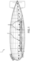
- an example airship 1 is shown incorporating a plurality of rotary disc valves 2 according to the disclosure.
- the rotary disc valves 2 are used to relieve internal helium pressure in the airship 1 as the airship ascends and ambient pressures decrease.
- a control system (not shown) opens one or more of the rotary disc valves 2 to allow helium to be discharged to the atmosphere. The control system then closes the rotary disc valves 2 when a desired reduced helium pressure within the airship is achieved.
- FIG. 2 illustrates the rotary disc valve 2 and related supporting structure 4, along with motor 6 which can be seen positioned at a periphery of the valve.
- the rotary disc valve 2 is shown in the open configuration such that an opening 8 in the disc is aligned to allow flow through the valve.
- FIGS. 3A - 3C show various details of the rotary disc valve 2 shown in FIG. 2 .
- FIG. 3A shows the position of seal 10 which seals between the supporting structure 4 (which in one embodiment is chimney support 28 - see FIG. 10C ) and the valve disc 11.
- FIG. 3B shows the projection 12 associated with the valve disc 11 positioned within groove 14 associated with the valve body 16.
- the projection 12 rides within the angled portion 18 of the groove 14, and the projection 12 and valve disc 11 move axially with respect to the valve body 16 and the seal 10. This axial movement serves to decompress the seal and allows the valve disc 11 to rotate unimpeded by frictional forces associated with engagement between the valve disc 11 and the seal 10.
- FIG. 3C shows the interengagement between a pinion 20 of the motor 6 and external gear teeth 22 disposed on a periphery of the valve disc assembly.
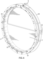
- FIGS. 4 and 5 shows the rotary disc valve 2 including guide assembly 23 and skirt support 24, valve disc assembly 26, and chimney support 28.
- Motor 6 is shown coupled to the chimney support 28 such that pinion 20 engages gear teeth 22 on the periphery of the valve disc assembly 26.
- Switch assembly 30 (the function of which will be described in greater detail later) is also shown coupled to the chimney support 28.
- FIGS. 6A-6C illustrate aspects of the skirt support 24 and associated internal support ring 32.
- the skirt support 24 has a solid ring-shaped projection portion 34 which engages a recess 36 formed in the inner support ring 32 to hold the two together.
- the inner support ring 32 is shown as formed from a series of arc-shaped segments coupled together to form the ring.
- the skirt support 24 also serves as a mechanical interface with support structure associated with the airship 1
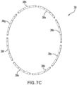
- FIGS. 7A-7C illustrate the skirt support 24 and internal support ring 32 coupled to an external support 38.
- the external support 38 comprises a plurality of arc-shaped segments 38a-h which together form a ring shape.
- the arc-shaped segments 38a-h engage a first face 24a of the skirt support 24, while the internal support ring 32 engages a second face 24b of the skirt support.
- the skirt support 24 is fixed between the internal support ring 32 and the external support 38.
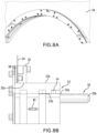
- FIG. 8A-8C show the guide assembly 23 engaged with the internal support ring 32, skirt support 24, and external support 38.
- the guide assembly 23 is a ring-shaped member having an outer surface 23a and an inner surface 23b.
- the outer surface 23a abuts an inner surface 32a of the internal support ring 32, while the inner surface 23b includes a plurality of grooves14 that guide the rotational movement of the valve disc assembly 26 via their interaction with projections 12.
- a plurality of rollers 40 are embedded in the inner surface 32a of the internal support ring 32. These rollers 40 are configured to engage the valve disc assembly 26 to facilitate a smooth rotation of the valve disc assembly.
- a spacer 25 is coupled to the guide assembly 23.
- the spacer 25 in the illustrated arrangement is a cylindrical member coupled at a first end 25a to the guide assembly 23.
- the second end 25b extends away from the guide assembly and is coupleable to a chimney support ( see FIG. 10B ).
- FIG. 8C shows the grooves 14 disposed in the inner surface 23b of the guide assembly 23. These grooves 14 interact with the associated projections 12 to hold the valve disc 11 in place and importantly to allow the valve disc assembly 26 to translate to release the engagement between the valve disc 11 and the seal 10 and to guide the valve disc assembly 26 as it rotates between the open and closed positions.
- one of the projections 12 of the valve disc assembly 26 is positioned within groove 14 in the inner surface 23b of the guide assembly 23.
- the valve disc assembly 26 is provided with four projections 12 positioned at 12, 3, 6 and 9 o'clock, respectively, on the valve disc assembly 26. Providing multiple projections 12 and a plurality of rollers 40 ( FIG. 8A ) ensures smooth rotation and axial movement of the valve disc assembly 26 with respect to guide assembly 23.
- FIGS. 10A-10C show chimney support 28 engaged with the spacer 25 of the guide assembly 23.
- the chimney support 28 is a circular member that holds the D-shaped flexible seal ring 10 which surrounds an opening 46 that is approximately the same shape and dimension of the opening 8 in the valve disc assembly 26.
- a D-shaped groove 48 is provided in the chimney support 28 surrounding the opening 46. The groove 48 receives and retains a portion of the flexible seal ring 10.
- the flexible seal ring 10 is glued to the groove 48.
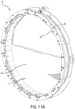
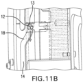
- FIGS. 11A-11C the rotary disc valve 2 is shown in the closed position.
- the opening 8 in the disc 11 is positioned so that it does not align with the opening 48 in the chimney support 28.
- the seal ring 10 engages the solid portion 9 of the disc 11 so that no flow is allowed through the valve 2.
- the projection is positioned in the first end 13 of the groove 14 so the valve disc assembly 26 is held tight against the seal.
- FIGS. 12A-12C show the valve 2 as it is starting to move toward the open position.
- the pinion 20 of the motor 6 engages and rotates the teeth 22 of the gear parts 42 which rotates the valve disc assembly 26, including valve disc 11, toward the open position.
- the projection 12 slides within the angled portion 18 of the groove.
- the angled portion 18 of the groove forms an oblique angle ⁇ with respect to the longitudinal axis A-A of the valve 2 so that as the disc assembly 26 rotates, the projection 12 slides within the angled portion 18 of the groove and the disc assembly 26 moves in the direction of arrow "B".
- a component of its motion is parallel to the longitudinal axis A-A of the valve 2, which moves the disc assembly away from the chimney support 28 and the seal 10, thus decompressing the seal.
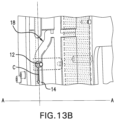
- FIGS. 13A-13C show the valve as the valve disc continues to rotate to the open position.
- the motor 6 continues to rotate the pinion 20, the teeth 22 of the gear parts 42 continue to rotate the valve disc assembly 26 toward the open position.
- the projection 12 exits the angled portion 18 of the groove 14 and enters the main portion of the groove, moving in the direction of arrow "C", which is oriented perpendicular to the longitudinal axis A-A of the valve.
- the valve disc 11 is offset from the seal 10 by a distance "D" ( FIG. 13C ). In one example embodiment this distance "D" is about 14 millimeters (mm).
- the valve disc assembly 26 rotates from the closed position toward the open position, the first projection 17a disengages the first sensor 31, and the valve disc assembly continues to rotate (via interaction with the pinion 20) until the second one of the projections 17b engages the second sensor 33.
- the switch assembly 30 signals the motor to stop rotating the pinion 20.
- the valve disc assembly 26 is rotated (again, via interaction with the pinion 20) toward the closed position such that the second projection 17b disengages the second sensor 33.
- the valve disc assembly continues to rotate until the first projection 17a engages the first sensor 31, whereupon the switch assembly 30 signals the motor to stop rotating the pinion 20.
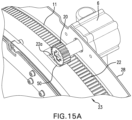
- FIGS. 15A-15BC shows the relative positions of the motor and pinion and the external gearing when the valve is in the closed position ( FIG. 15A ) and the open position ( FIG. 15B ).
- the valve disc 11 In the closed position, the valve disc 11 is disposed directly adjacent to the chimney support 28 so the seal (not shown) engages the valve disc.
- the pinion 20 can be seen engaging a first lateral portion 22a of the teeth 22 of the gear parts.
- a recess 50 in the guide assembly 23 receives at least a portion of the pinion.
- valve disc 11 In the open position shown in FIG. 15B , the valve disc 11 is separated from the chimney support 28 by distance "D", which as previously mentioned can be about 14 mm. In this position the pinion engages a second lateral portion 22b of the teeth 22 of the gear parts.
- valve disc 11 movement of the valve disc 11 toward and away from the chimney support 28 does not affect the interaction between the pinion 20 and the teeth 22 of the gear parts, and the motor 6 and pinion 20 are able to engage and rotate the valve disc assembly 26 through the full range of motion of the valve disc 11 (from closed to open, then from open to closed).
- Connection references are to be construed broadly and may include intermediate members between a collection of elements and relative to movement between elements unless otherwise indicated. As such, connection references do not necessarily infer that two elements are directly connected and in fixed relation to each other. All rotational references describe relative movement between the various elements. Identification references (e.g., primary, secondary, first, second, third, fourth, etc.) are not intended to connote importance or priority but are used to distinguish one feature from another.
- the drawings are for purposes of illustration only and the dimensions, positions, order and relative to sizes reflected in the drawings attached hereto may vary.
Landscapes
- Engineering & Computer Science (AREA)
- General Engineering & Computer Science (AREA)
- Mechanical Engineering (AREA)
- Aviation & Aerospace Engineering (AREA)
- Lift Valve (AREA)
Claims (15)
- Drehschieberventil (2), umfassend:eine Führungsanordnung (23), umfassend ein ringförmiges Element, auf dessen Innenoberfläche (23b) eine Nut (14) eingerichtet ist;eine Ventilscheibenanordnung (26), die mit der Führungsanordnung drehbar gekoppelt ist, die Ventilscheibenanordnung umfassend:eine Ventilscheibe (11),einen Vorsprung (12), der innerhalb der Nut der Führungsanordnung aufgenommen ist; undeine Kaminstütze (28), die mit der Führungsanordnung gekoppelt ist, wobei die Kaminstütze ein Dichtungselement (10) zum selektiven Abdichten gegenüber der Ventilscheibe einschließt;wobei die Nut (14) einen Hauptabschnitt, der senkrecht zu einer Längsachse des Drehschieberventils ausgerichtet ist, und einen abgewinkelten Abschnitt (18) aufweist, der in einem schrägen Winkel in Bezug auf die Längsachse ausgerichtet ist; undwobei, wenn das Drehschieberventil von einer geschlossenen Position in eine geöffnete Position bewegt wird, die Ventilscheibenanordnung in Bezug auf die Führungsanordnung in eine erste Richtung gedreht wird, was den Vorsprung entlang des abgewinkelten Abschnitts der Nut bewegt, wodurch die Ventilscheibe von der Dichtung weg bewegt wird, um die Dichtung zu dekomprimieren; undwobei, wenn die Ventilscheibenanordnung von der geöffneten Position in die geschlossene Position bewegt wird, die Ventilscheibenanordnung in Bezug auf die Führungsanordnung in eine zweite Richtung gedreht wird, was den Vorsprung entlang des abgewinkelten Abschnitts der Nut bewegt, wodurch die Ventilscheibe in zu der Dichtung bewegt wird, um die Dichtung zu komprimieren.
- Drehschieberventil nach Anspruch 1, wobei der abgewinkelte Abschnitt (18) der Nut angrenzend an ein erstes Ende (13) der Nut positioniert ist.
- Drehschieberventil nach Anspruch 2, wobei der Hauptabschnitt der Nut zwischen dem abgewinkelten Abschnitt und einem zweiten Ende (15) der Nut positioniert ist.
- Drehschieberventil nach Anspruch 1, wobei, wenn das Drehschieberventil in der geschlossenen Position ist, die Dichtung die Ventilscheibe in Eingriff nimmt und wobei, wenn das Drehschieberventil in der geöffneten Position ist, die Dichtung in einem Abstand "D" von der Ventilscheibe entfernt eingerichtet ist.
- Drehschieberventil nach Anspruch 4, wobei der Abstand "D" etwa 14 Millimeter beträgt.
- Drehschieberventil nach Anspruch 1, ferner umfassend eine Schürzenstütze (24), die mit der Führungsanordnung (23) gekoppelt ist, wobei die Schürzenstütze konfiguriert ist, um das Drehschieberventil mit einer umgebenden Struktur zu koppeln.
- Drehschieberventil nach Anspruch 1, wobei die Kaminstütze einen geöffneten Abschnitt und einen festen Abschnitt aufweist, wobei, wenn das Ventil in der geöffneten Position ist, sich der geöffnete Abschnitt der Kaminstütze mit einem geöffneten Abschnitt der Ventilscheibe ausrichtet, und wobei, wenn das Ventil in der geschlossenen Position ist, sich der geöffnete Abschnitt (46) der Kaminstütze mit einem festen Abschnitt der Ventilscheibe ausrichtet.
- Drehschieberventil nach Anspruch 7, wobei der geöffnete Abschnitt (46) der Kaminstütze D-förmig ist und wobei die Dichtung ein D-förmiges Element ist, das mit der Kaminstütze um den Umfang des D-förmigen geöffneten Abschnitts gekoppelt ist.
- Drehschieberventil nach Anspruch 1, ferner umfassend einen Motor (6), der mit der Kaminstütze gekoppelt ist, wobei der Motor ein drehbares Ritzel (20) einschließt, die Ventilscheibenanordnung umfassend eine Vielzahl von Zahnradteilen, wobei jedes der Vielzahl von Zahnradteilen Außenzähne (22) zum Ineingriffnehmen des drehbaren Ritzel aufweist, sodass, wenn sich der Motor in eine erste Richtung wendet, das Ritzel die Zähne in Eingriff nimmt, um die Ventilscheibenanordnung in eine erste Richtung zu bewegen, um das Ventil zu öffnen, und wenn sich der Motor in eine zweite Richtung wendet, das Ritzel die Zähne in Eingriff nimmt, um die Ventilscheibenanordnung in eine zweite Richtung zu bewegen, um das Ventil zu schließen.
- Drehschieberventil nach Anspruch 9, wobei die Außenzähne der Zahnradteile erste (22a) und zweite (22b) seitliche Abschnitte aufweisen, und wobei, wenn das Drehschieberventil in der geschlossenen Position ist, das Ritzel die ersten seitlichen Abschnitte der Außenzähne in Eingriff nimmt, und wobei, wenn das Drehschieberventil in der geöffneten Position ist, das Ritzel die zweiten seitlichen Abschnitte der Außenzähne in Eingriff nimmt.
- Drehschieberventil nach Anspruch 10, wobei die Führungsanordnung eine Aussparung zum Aufnehmen eines Abschnitts des Ritzels einschließt, wenn das Ritzel mit den ersten seitlichen Abschnitten der Außenzähne in Eingriff steht.
- Drehschieberventil nach Anspruch 1, ferner umfassend einen Sensor (31, 33), der konfiguriert ist, um eine Position der Ventilschieberanordnung zu erfassen und dem Motor zu signalisieren, das Drehen des Ritzels zu stoppen, wenn durch den Sensor bestimmt wird, dass sich das Drehschieberventil von der geschlossenen Position in die vollständig geöffnete Position bewegt hat.
- Drehschieberventil nach Anspruch 12, wobei der Sensor ferner konfiguriert ist, um dem Motor zu signalisieren, das Drehen des Ritzels zu stoppen, wenn durch den Sensor bestimmt wird, dass sich das Drehschieberventil von der geschlossenen Position in die vollständig geöffnete Position bewegt hat.
- Luftschiff, das eine Vielzahl von Drehschieberventilen nach Anspruch 1 einschließt.
- Verwendung eines Drehschieberventils nach Anspruch 1 als ein Sicherheitsdruckablassventil.
Applications Claiming Priority (1)
| Application Number | Priority Date | Filing Date | Title |
|---|---|---|---|
| US202363439909P | 2023-01-19 | 2023-01-19 |
Publications (3)
| Publication Number | Publication Date |
|---|---|
| EP4403804A1 EP4403804A1 (de) | 2024-07-24 |
| EP4403804B1 true EP4403804B1 (de) | 2025-05-07 |
| EP4403804C0 EP4403804C0 (de) | 2025-05-07 |
Family
ID=89619581
Family Applications (1)
| Application Number | Title | Priority Date | Filing Date |
|---|---|---|---|
| EP24151854.7A Active EP4403804B1 (de) | 2023-01-19 | 2024-01-15 | Drehschieberventil |
Country Status (2)
| Country | Link |
|---|---|
| US (1) | US12320440B2 (de) |
| EP (1) | EP4403804B1 (de) |
Family Cites Families (5)
| Publication number | Priority date | Publication date | Assignee | Title |
|---|---|---|---|---|
| GB706371A (en) | 1952-01-18 | 1954-03-31 | Glover & Co Ltd W T | Improvements in the manufacture of insulated electric conductors |
| GB874169A (en) | 1958-07-24 | 1961-08-02 | Koppers Gmbh Heinrich | Improvements relating to rotary disc valves |
| DE58905222D1 (de) | 1988-06-03 | 1993-09-16 | Zeppelin Schuettguttech Gmbh | Dichtungsanordnung. |
| WO2013073039A1 (ja) | 2011-11-17 | 2013-05-23 | プログレッシオ合同会社 | 真空用ゲートバルブ |
| EP3159587A1 (de) | 2015-02-16 | 2017-04-26 | King Lai Hygienic Materials Co., Ltd. | Schieberventil mit sicherem dichtungsmechanismus |
-
2024
- 2024-01-05 US US18/405,167 patent/US12320440B2/en active Active
- 2024-01-15 EP EP24151854.7A patent/EP4403804B1/de active Active
Also Published As
| Publication number | Publication date |
|---|---|
| EP4403804A1 (de) | 2024-07-24 |
| US20240247724A1 (en) | 2024-07-25 |
| US12320440B2 (en) | 2025-06-03 |
| EP4403804C0 (de) | 2025-05-07 |
Similar Documents
| Publication | Publication Date | Title |
|---|---|---|
| US9506571B1 (en) | Cryogenic cam butterfly valve | |
| CA1105438A (en) | Sealing ring | |
| US9279505B2 (en) | Valve core assembly and valve adopting the valve core assembly | |
| US4394022A (en) | Mechanically expandable annular seal | |
| US4554948A (en) | Straight-way valve | |
| US3109623A (en) | Valve construction having resilient sealing means | |
| CA1122188A (en) | Fluid control valve and method | |
| CA1192177A (en) | Valve assembly and seat | |
| US4569365A (en) | Device for detecting the operation of a valve | |
| WO2016052372A1 (ja) | 流量制御装置及び車両 | |
| EP4403804A1 (de) | Drehschieberventil | |
| US4024890A (en) | Rotary valve | |
| US5609185A (en) | Valve indicator and handle assembly | |
| CA2550524C (en) | Coaxial valve | |
| EP3338012B1 (de) | Drosselventile mit axialdichtung | |
| CN217977405U (zh) | 一种下料阀 | |
| CN113586748A (zh) | 一种可定量调节流体流量的阀门及其调节方法 | |
| US4150694A (en) | Rotary plug valve | |
| EP0551724B1 (de) | Stellvorrichtung für ein Drehventil | |
| CN118912229B (zh) | 一种压力平衡式低扭矩密封球阀 | |
| US20240410474A1 (en) | Ball valve, in particular for explosion isolation in process pipelines | |
| CN216590127U (zh) | 一种弹簧式稳压器安全阀 | |
| US5029809A (en) | Valve-control device and valve having such a control device | |
| CN114909516B (zh) | 一种加氢反应器的泄压装置 | |
| US4482128A (en) | High pressure cam seal valve |
Legal Events
| Date | Code | Title | Description |
|---|---|---|---|
| PUAI | Public reference made under article 153(3) epc to a published international application that has entered the european phase |
Free format text: ORIGINAL CODE: 0009012 |
|
| STAA | Information on the status of an ep patent application or granted ep patent |
Free format text: STATUS: THE APPLICATION HAS BEEN PUBLISHED |
|
| AK | Designated contracting states |
Kind code of ref document: A1 Designated state(s): AL AT BE BG CH CY CZ DE DK EE ES FI FR GB GR HR HU IE IS IT LI LT LU LV MC ME MK MT NL NO PL PT RO RS SE SI SK SM TR |
|
| STAA | Information on the status of an ep patent application or granted ep patent |
Free format text: STATUS: REQUEST FOR EXAMINATION WAS MADE |
|
| 17P | Request for examination filed |
Effective date: 20240908 |
|
| RBV | Designated contracting states (corrected) |
Designated state(s): AL AT BE BG CH CY CZ DE DK EE ES FI FR GB GR HR HU IE IS IT LI LT LU LV MC ME MK MT NL NO PL PT RO RS SE SI SK SM TR |
|
| GRAP | Despatch of communication of intention to grant a patent |
Free format text: ORIGINAL CODE: EPIDOSNIGR1 |
|
| STAA | Information on the status of an ep patent application or granted ep patent |
Free format text: STATUS: GRANT OF PATENT IS INTENDED |
|
| RIC1 | Information provided on ipc code assigned before grant |
Ipc: B64B 1/00 20060101ALI20241219BHEP Ipc: B64B 1/64 20060101ALI20241219BHEP Ipc: F16K 31/53 20060101ALI20241219BHEP Ipc: F16K 31/524 20060101ALI20241219BHEP Ipc: F16K 3/10 20060101ALI20241219BHEP Ipc: F16K 3/08 20060101AFI20241219BHEP |
|
| INTG | Intention to grant announced |
Effective date: 20250114 |
|
| GRAS | Grant fee paid |
Free format text: ORIGINAL CODE: EPIDOSNIGR3 |
|
| GRAA | (expected) grant |
Free format text: ORIGINAL CODE: 0009210 |
|
| STAA | Information on the status of an ep patent application or granted ep patent |
Free format text: STATUS: THE PATENT HAS BEEN GRANTED |
|
| AK | Designated contracting states |
Kind code of ref document: B1 Designated state(s): AL AT BE BG CH CY CZ DE DK EE ES FI FR GB GR HR HU IE IS IT LI LT LU LV MC ME MK MT NL NO PL PT RO RS SE SI SK SM TR |
|
| REG | Reference to a national code |
Ref country code: GB Ref legal event code: FG4D |
|
| REG | Reference to a national code |
Ref country code: CH Ref legal event code: EP |
|
| REG | Reference to a national code |
Ref country code: DE Ref legal event code: R096 Ref document number: 602024000095 Country of ref document: DE |
|
| REG | Reference to a national code |
Ref country code: IE Ref legal event code: FG4D |
|
| U01 | Request for unitary effect filed |
Effective date: 20250523 |
|
| U07 | Unitary effect registered |
Designated state(s): AT BE BG DE DK EE FI FR IT LT LU LV MT NL PT RO SE SI Effective date: 20250603 |
|
| PG25 | Lapsed in a contracting state [announced via postgrant information from national office to epo] |
Ref country code: ES Free format text: LAPSE BECAUSE OF FAILURE TO SUBMIT A TRANSLATION OF THE DESCRIPTION OR TO PAY THE FEE WITHIN THE PRESCRIBED TIME-LIMIT Effective date: 20250507 |
|
| PG25 | Lapsed in a contracting state [announced via postgrant information from national office to epo] |
Ref country code: NO Free format text: LAPSE BECAUSE OF FAILURE TO SUBMIT A TRANSLATION OF THE DESCRIPTION OR TO PAY THE FEE WITHIN THE PRESCRIBED TIME-LIMIT Effective date: 20250807 Ref country code: GR Free format text: LAPSE BECAUSE OF FAILURE TO SUBMIT A TRANSLATION OF THE DESCRIPTION OR TO PAY THE FEE WITHIN THE PRESCRIBED TIME-LIMIT Effective date: 20250808 |
|
| PG25 | Lapsed in a contracting state [announced via postgrant information from national office to epo] |
Ref country code: PL Free format text: LAPSE BECAUSE OF FAILURE TO SUBMIT A TRANSLATION OF THE DESCRIPTION OR TO PAY THE FEE WITHIN THE PRESCRIBED TIME-LIMIT Effective date: 20250507 |
|
| PG25 | Lapsed in a contracting state [announced via postgrant information from national office to epo] |
Ref country code: HR Free format text: LAPSE BECAUSE OF FAILURE TO SUBMIT A TRANSLATION OF THE DESCRIPTION OR TO PAY THE FEE WITHIN THE PRESCRIBED TIME-LIMIT Effective date: 20250507 |
|
| PG25 | Lapsed in a contracting state [announced via postgrant information from national office to epo] |
Ref country code: RS Free format text: LAPSE BECAUSE OF FAILURE TO SUBMIT A TRANSLATION OF THE DESCRIPTION OR TO PAY THE FEE WITHIN THE PRESCRIBED TIME-LIMIT Effective date: 20250807 |
|
| PG25 | Lapsed in a contracting state [announced via postgrant information from national office to epo] |
Ref country code: IS Free format text: LAPSE BECAUSE OF FAILURE TO SUBMIT A TRANSLATION OF THE DESCRIPTION OR TO PAY THE FEE WITHIN THE PRESCRIBED TIME-LIMIT Effective date: 20250907 |
|
| PG25 | Lapsed in a contracting state [announced via postgrant information from national office to epo] |
Ref country code: SM Free format text: LAPSE BECAUSE OF FAILURE TO SUBMIT A TRANSLATION OF THE DESCRIPTION OR TO PAY THE FEE WITHIN THE PRESCRIBED TIME-LIMIT Effective date: 20250507 |
|
| U20 | Renewal fee for the european patent with unitary effect paid |
Year of fee payment: 3 Effective date: 20251205 |
|
| PG25 | Lapsed in a contracting state [announced via postgrant information from national office to epo] |
Ref country code: CZ Free format text: LAPSE BECAUSE OF FAILURE TO SUBMIT A TRANSLATION OF THE DESCRIPTION OR TO PAY THE FEE WITHIN THE PRESCRIBED TIME-LIMIT Effective date: 20250507 |
|
| PG25 | Lapsed in a contracting state [announced via postgrant information from national office to epo] |
Ref country code: SK Free format text: LAPSE BECAUSE OF FAILURE TO SUBMIT A TRANSLATION OF THE DESCRIPTION OR TO PAY THE FEE WITHIN THE PRESCRIBED TIME-LIMIT Effective date: 20250507 |
|
| PLBE | No opposition filed within time limit |
Free format text: ORIGINAL CODE: 0009261 |
|
| STAA | Information on the status of an ep patent application or granted ep patent |
Free format text: STATUS: NO OPPOSITION FILED WITHIN TIME LIMIT |
|
| REG | Reference to a national code |
Ref country code: CH Ref legal event code: L10 Free format text: ST27 STATUS EVENT CODE: U-0-0-L10-L00 (AS PROVIDED BY THE NATIONAL OFFICE) Effective date: 20260318 |
|
| 26N | No opposition filed |
Effective date: 20260210 |