EP4403804B1 - Rotary disc valve - Google Patents
Rotary disc valve Download PDFInfo
- Publication number
- EP4403804B1 EP4403804B1 EP24151854.7A EP24151854A EP4403804B1 EP 4403804 B1 EP4403804 B1 EP 4403804B1 EP 24151854 A EP24151854 A EP 24151854A EP 4403804 B1 EP4403804 B1 EP 4403804B1
- Authority
- EP
- European Patent Office
- Prior art keywords
- valve
- rotary disc
- disc
- assembly
- rotary
- Prior art date
- Legal status (The legal status is an assumption and is not a legal conclusion. Google has not performed a legal analysis and makes no representation as to the accuracy of the status listed.)
- Active
Links
Images











Classifications
-
- F—MECHANICAL ENGINEERING; LIGHTING; HEATING; WEAPONS; BLASTING
- F16—ENGINEERING ELEMENTS AND UNITS; GENERAL MEASURES FOR PRODUCING AND MAINTAINING EFFECTIVE FUNCTIONING OF MACHINES OR INSTALLATIONS; THERMAL INSULATION IN GENERAL
- F16K—VALVES; TAPS; COCKS; ACTUATING-FLOATS; DEVICES FOR VENTING OR AERATING
- F16K3/00—Gate valves or sliding valves, i.e. cut-off apparatus with closing members having a sliding movement along the seat for opening and closing
- F16K3/02—Gate valves or sliding valves, i.e. cut-off apparatus with closing members having a sliding movement along the seat for opening and closing with flat sealing faces; Packings therefor
- F16K3/04—Gate valves or sliding valves, i.e. cut-off apparatus with closing members having a sliding movement along the seat for opening and closing with flat sealing faces; Packings therefor with pivoted closure members
- F16K3/06—Gate valves or sliding valves, i.e. cut-off apparatus with closing members having a sliding movement along the seat for opening and closing with flat sealing faces; Packings therefor with pivoted closure members in the form of closure plates arranged between supply and discharge passages
- F16K3/08—Gate valves or sliding valves, i.e. cut-off apparatus with closing members having a sliding movement along the seat for opening and closing with flat sealing faces; Packings therefor with pivoted closure members in the form of closure plates arranged between supply and discharge passages with circular plates rotatable around their centres
-
- B—PERFORMING OPERATIONS; TRANSPORTING
- B64—AIRCRAFT; AVIATION; COSMONAUTICS
- B64B—LIGHTER-THAN AIR AIRCRAFT
- B64B1/00—Lighter-than-air aircraft
- B64B1/58—Arrangements or construction of gas-bags; Filling arrangements
- B64B1/64—Gas valve operating mechanisms
-
- F—MECHANICAL ENGINEERING; LIGHTING; HEATING; WEAPONS; BLASTING
- F16—ENGINEERING ELEMENTS AND UNITS; GENERAL MEASURES FOR PRODUCING AND MAINTAINING EFFECTIVE FUNCTIONING OF MACHINES OR INSTALLATIONS; THERMAL INSULATION IN GENERAL
- F16K—VALVES; TAPS; COCKS; ACTUATING-FLOATS; DEVICES FOR VENTING OR AERATING
- F16K3/00—Gate valves or sliding valves, i.e. cut-off apparatus with closing members having a sliding movement along the seat for opening and closing
- F16K3/02—Gate valves or sliding valves, i.e. cut-off apparatus with closing members having a sliding movement along the seat for opening and closing with flat sealing faces; Packings therefor
- F16K3/0254—Gate valves or sliding valves, i.e. cut-off apparatus with closing members having a sliding movement along the seat for opening and closing with flat sealing faces; Packings therefor being operated by particular means
-
- F—MECHANICAL ENGINEERING; LIGHTING; HEATING; WEAPONS; BLASTING
- F16—ENGINEERING ELEMENTS AND UNITS; GENERAL MEASURES FOR PRODUCING AND MAINTAINING EFFECTIVE FUNCTIONING OF MACHINES OR INSTALLATIONS; THERMAL INSULATION IN GENERAL
- F16K—VALVES; TAPS; COCKS; ACTUATING-FLOATS; DEVICES FOR VENTING OR AERATING
- F16K3/00—Gate valves or sliding valves, i.e. cut-off apparatus with closing members having a sliding movement along the seat for opening and closing
- F16K3/02—Gate valves or sliding valves, i.e. cut-off apparatus with closing members having a sliding movement along the seat for opening and closing with flat sealing faces; Packings therefor
- F16K3/04—Gate valves or sliding valves, i.e. cut-off apparatus with closing members having a sliding movement along the seat for opening and closing with flat sealing faces; Packings therefor with pivoted closure members
- F16K3/06—Gate valves or sliding valves, i.e. cut-off apparatus with closing members having a sliding movement along the seat for opening and closing with flat sealing faces; Packings therefor with pivoted closure members in the form of closure plates arranged between supply and discharge passages
- F16K3/08—Gate valves or sliding valves, i.e. cut-off apparatus with closing members having a sliding movement along the seat for opening and closing with flat sealing faces; Packings therefor with pivoted closure members in the form of closure plates arranged between supply and discharge passages with circular plates rotatable around their centres
- F16K3/085—Gate valves or sliding valves, i.e. cut-off apparatus with closing members having a sliding movement along the seat for opening and closing with flat sealing faces; Packings therefor with pivoted closure members in the form of closure plates arranged between supply and discharge passages with circular plates rotatable around their centres the axis of supply passage and the axis of discharge passage being coaxial and parallel to the axis of rotation of the plates
-
- F—MECHANICAL ENGINEERING; LIGHTING; HEATING; WEAPONS; BLASTING
- F16—ENGINEERING ELEMENTS AND UNITS; GENERAL MEASURES FOR PRODUCING AND MAINTAINING EFFECTIVE FUNCTIONING OF MACHINES OR INSTALLATIONS; THERMAL INSULATION IN GENERAL
- F16K—VALVES; TAPS; COCKS; ACTUATING-FLOATS; DEVICES FOR VENTING OR AERATING
- F16K3/00—Gate valves or sliding valves, i.e. cut-off apparatus with closing members having a sliding movement along the seat for opening and closing
- F16K3/02—Gate valves or sliding valves, i.e. cut-off apparatus with closing members having a sliding movement along the seat for opening and closing with flat sealing faces; Packings therefor
- F16K3/04—Gate valves or sliding valves, i.e. cut-off apparatus with closing members having a sliding movement along the seat for opening and closing with flat sealing faces; Packings therefor with pivoted closure members
- F16K3/10—Gate valves or sliding valves, i.e. cut-off apparatus with closing members having a sliding movement along the seat for opening and closing with flat sealing faces; Packings therefor with pivoted closure members with special arrangements for separating the sealing faces or for pressing them together
-
- F—MECHANICAL ENGINEERING; LIGHTING; HEATING; WEAPONS; BLASTING
- F16—ENGINEERING ELEMENTS AND UNITS; GENERAL MEASURES FOR PRODUCING AND MAINTAINING EFFECTIVE FUNCTIONING OF MACHINES OR INSTALLATIONS; THERMAL INSULATION IN GENERAL
- F16K—VALVES; TAPS; COCKS; ACTUATING-FLOATS; DEVICES FOR VENTING OR AERATING
- F16K3/00—Gate valves or sliding valves, i.e. cut-off apparatus with closing members having a sliding movement along the seat for opening and closing
- F16K3/30—Details
- F16K3/316—Guiding of the slide
-
- F—MECHANICAL ENGINEERING; LIGHTING; HEATING; WEAPONS; BLASTING
- F16—ENGINEERING ELEMENTS AND UNITS; GENERAL MEASURES FOR PRODUCING AND MAINTAINING EFFECTIVE FUNCTIONING OF MACHINES OR INSTALLATIONS; THERMAL INSULATION IN GENERAL
- F16K—VALVES; TAPS; COCKS; ACTUATING-FLOATS; DEVICES FOR VENTING OR AERATING
- F16K31/00—Actuating devices; Operating means; Releasing devices
- F16K31/44—Mechanical actuating means
- F16K31/52—Mechanical actuating means with crank, eccentric, or cam
- F16K31/524—Mechanical actuating means with crank, eccentric, or cam with a cam
- F16K31/52475—Mechanical actuating means with crank, eccentric, or cam with a cam comprising a sliding valve
-
- F—MECHANICAL ENGINEERING; LIGHTING; HEATING; WEAPONS; BLASTING
- F16—ENGINEERING ELEMENTS AND UNITS; GENERAL MEASURES FOR PRODUCING AND MAINTAINING EFFECTIVE FUNCTIONING OF MACHINES OR INSTALLATIONS; THERMAL INSULATION IN GENERAL
- F16K—VALVES; TAPS; COCKS; ACTUATING-FLOATS; DEVICES FOR VENTING OR AERATING
- F16K31/00—Actuating devices; Operating means; Releasing devices
- F16K31/44—Mechanical actuating means
- F16K31/52—Mechanical actuating means with crank, eccentric, or cam
- F16K31/528—Mechanical actuating means with crank, eccentric, or cam with pin and slot
- F16K31/5282—Mechanical actuating means with crank, eccentric, or cam with pin and slot comprising a pivoted disc or flap
-
- F—MECHANICAL ENGINEERING; LIGHTING; HEATING; WEAPONS; BLASTING
- F16—ENGINEERING ELEMENTS AND UNITS; GENERAL MEASURES FOR PRODUCING AND MAINTAINING EFFECTIVE FUNCTIONING OF MACHINES OR INSTALLATIONS; THERMAL INSULATION IN GENERAL
- F16K—VALVES; TAPS; COCKS; ACTUATING-FLOATS; DEVICES FOR VENTING OR AERATING
- F16K31/00—Actuating devices; Operating means; Releasing devices
- F16K31/44—Mechanical actuating means
- F16K31/52—Mechanical actuating means with crank, eccentric, or cam
- F16K31/528—Mechanical actuating means with crank, eccentric, or cam with pin and slot
- F16K31/5286—Mechanical actuating means with crank, eccentric, or cam with pin and slot comprising a sliding valve
-
- F—MECHANICAL ENGINEERING; LIGHTING; HEATING; WEAPONS; BLASTING
- F16—ENGINEERING ELEMENTS AND UNITS; GENERAL MEASURES FOR PRODUCING AND MAINTAINING EFFECTIVE FUNCTIONING OF MACHINES OR INSTALLATIONS; THERMAL INSULATION IN GENERAL
- F16K—VALVES; TAPS; COCKS; ACTUATING-FLOATS; DEVICES FOR VENTING OR AERATING
- F16K31/00—Actuating devices; Operating means; Releasing devices
- F16K31/44—Mechanical actuating means
- F16K31/53—Mechanical actuating means with toothed gearing
- F16K31/535—Mechanical actuating means with toothed gearing for rotating valves
-
- B—PERFORMING OPERATIONS; TRANSPORTING
- B64—AIRCRAFT; AVIATION; COSMONAUTICS
- B64B—LIGHTER-THAN AIR AIRCRAFT
- B64B1/00—Lighter-than-air aircraft
- B64B1/58—Arrangements or construction of gas-bags; Filling arrangements
- B64B1/62—Controlling gas pressure, heating, cooling, or discharging gas
Definitions
- the present disclosure relates generally to rotary valves, and in particular to rotary valves for use in pressure relief applications.
- valve types are known and used in gas handling applications. Such valves include flap gate valves, butterfly valves, guillotine valves, ball valves, and the like. For applications in which the valves are used to relieve gas from a gas-containing structure, such as during pressure relief operations, these valve types suffer from a variety of disadvantages.
- outward facing flap valves can suffer from the disadvantage that the flap is subjected to the force of wind (which, for example, in high altitude applications can approach or exceed 100 km/h). In such cases the high wind forces can twist and/or damage the flap.
- Using an inwardly oriented flap in such applications would solve the problem of flap damage but would undesirably require a fluid passage diameter of three or more times larger than an outward facing flap valve.
- a large structure would be required to take up the overhang of the valve (assuming a translation of 200 mm or more), and the associated motor would be in the fluid flow path, which is not acceptable.
- a motor located away from the valve would involve a large overhang, which is also not acceptable.
- Such geometries also require a structure to withstand the operating forces, which increases the overall mass of the valve.
- WO02013/073039A1 discloses a conventional rotary disc valve but fails to disclose a guide assembly and a valve disc assembly as defined in claim 1.
- a rotary valve is disclosed for use in gas pressure relief applications.
- the rotary valve is used to relieve internal helium pressures in an airship in the case of an overpressure condition within the helium-containing structure of the airship.
- the rotary valve is a safety valve used to relieve the pressure differential between internal helium pressure and the external ambient pressure as the airship rises.
- a rotary valve in which frictional opening forces are eliminated during rotation of the valve.
- a rotary valve includes a rotary disc that is guided within the external valve support structure, and a docking ramp that causes an axial translation of the rotating disc to compress the rotary disc against a seal when the valve is in the closed position to ensure a gas-tight seal exists when the valve is in the closed position.
- the kinematics of the ramp allow the rotary disc to be axially displaced away the seal so that the disc can be rotated to the open configuration (and then back to the closed configuration) without engaging the seal, thus eliminating friction between the two during cycling of the valve.
- Rotation of the rotary disc is obtained by the action of a motor that, via a pinion and worm connection, engages teeth on an outside surface of the rotary disc assembly.
- Axial translation of the rotary disc occurs by means of a radial guide groove formed in the valve housing, and within which one or more projections provided in the rotary disc assembly are received.
- the radial guide grooves are inclined at discrete locations (e.g., near the end of the rotational cycle) to axially move the rotary disc into and out of engagement with the valve seal.
- the groove/projection interaction thus induce a complex movement to the rotary disc.
- the projections of the rotary disc assembly ride within an inclined portion of the groove, which thereby moves the rotary disc outward and decompresses the seal.
- the remainder of the valve movement to the fully open configuration is unimpeded by any frictional contact with the seal.
- the rotary disc is pushed outwards and decompresses the seal.
- a reverse movement transitions the rotary valve from the fully open configuration to the closed configuration.
- the arrangement of the rotary valve avoids wind entrapment and reduces aerodynamic stresses.
- the reduction in such stresses allows the mass of the rotary valve and any associated equipment to be reduced.
- by locating the valve motor on the periphery of the valve access for repairs is simplified, and the suspended mass associated with the valve is reduced.
- Additional advantages to the disclosed rotary valve include reduced size and weight, improved design and operation, more precise control, improved maintenance, and improved robustness, as compared to conventional designs.
- valve disc assembly When the rotary disc valve is moved from a closed position toward an open position the valve disc assembly is rotated in a first direction with respect to the guide assembly, which moves the projection along the angled portion of the groove, thereby moving the valve disc away from the seal to decompress the seal.
- valve disc assembly When the valve disc assembly is moved from the open position to the closed position the valve disc assembly is rotated in a second direction with respect to the guide assembly, which moves the projection along the angled portion of the groove, thereby moving the valve disc toward the seal to compress the seal.
- the angled portion of the groove is positioned adjacent to a first end of the groove.
- the main portion of the groove is positioned between the angled portion and a second end of the groove.
- the rotary disc valve includes a skirt support coupled to the guide assembly, the skirt support configured to couple the rotary disc valve to surrounding structure.
- the rotary disc valve includes a chimney support coupled to the guide assembly, the chimney support having an open portion and a solid portion.
- the open portion of the chimney support aligns with an open portion of the valve disc
- the open portion of the chimney support aligns with a solid portion of the valve disc.
- the open portion of the chimney support is D-shaped, and the seal is a D-shaped member coupled to the chimney support around the perimeter of the D-shaped open portion.
- the rotary disc valve can include a motor coupled to the chimney support.
- the motor includes a rotatable pinion.
- the valve disc assembly includes a plurality of gear parts, each of the plurality of gear parts having external teeth for engaging the rotatable pinion so that when the motor turns in a first direction the pinion engages the teeth to move the valve disc assembly in a first direction to open the valve.
- the motor turns in a second direction the pinion engages the teeth to move the valve disc assembly in a second direction to close the valve.
- the external teeth of the gear parts have first and second lateral portions.
- the pinion engages the first lateral portions of the external teeth.
- the pinion engages the second lateral portions of the external teeth.
- the guide assembly includes a recess for receiving a portion of the pinion when the pinion is engaged with the first lateral portions of the external teeth.
- the rotary disc valve can include a sensor configured to sense a position of the valve disc assembly and for signaling the motor to stop rotating the pinion when the rotary disc valve is determined by the sensor to have moved from the closed position to the fully open position.
- the sensor can be configured to signal the motor to stop rotating the pinion when the rotary disc valve is determined by the sensor to have moved from the closed position to the fully open position.
- This disclosure relates to rotary disc valves comprising a housing defining at least one passage for fluid to be controlled by the valve and a rotatable valve disc having an opening that can be brought into and out of alignment with a fluid flow passage through rotation of the disc within its own plane.
- the disclosure includes an arrangement in which the disc is axially shifted away from the seal as the valve is moved from the closed position to the open position to as to reduce or eliminate frictional forces associated with rotating the disc.
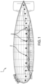
- an example airship 1 is shown incorporating a plurality of rotary disc valves 2 according to the disclosure.
- the rotary disc valves 2 are used to relieve internal helium pressure in the airship 1 as the airship ascends and ambient pressures decrease.
- a control system (not shown) opens one or more of the rotary disc valves 2 to allow helium to be discharged to the atmosphere. The control system then closes the rotary disc valves 2 when a desired reduced helium pressure within the airship is achieved.
- FIG. 2 illustrates the rotary disc valve 2 and related supporting structure 4, along with motor 6 which can be seen positioned at a periphery of the valve.
- the rotary disc valve 2 is shown in the open configuration such that an opening 8 in the disc is aligned to allow flow through the valve.
- FIGS. 3A - 3C show various details of the rotary disc valve 2 shown in FIG. 2 .
- FIG. 3A shows the position of seal 10 which seals between the supporting structure 4 (which in one embodiment is chimney support 28 - see FIG. 10C ) and the valve disc 11.
- FIG. 3B shows the projection 12 associated with the valve disc 11 positioned within groove 14 associated with the valve body 16.
- the projection 12 rides within the angled portion 18 of the groove 14, and the projection 12 and valve disc 11 move axially with respect to the valve body 16 and the seal 10. This axial movement serves to decompress the seal and allows the valve disc 11 to rotate unimpeded by frictional forces associated with engagement between the valve disc 11 and the seal 10.
- FIG. 3C shows the interengagement between a pinion 20 of the motor 6 and external gear teeth 22 disposed on a periphery of the valve disc assembly.
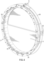
- FIGS. 4 and 5 shows the rotary disc valve 2 including guide assembly 23 and skirt support 24, valve disc assembly 26, and chimney support 28.
- Motor 6 is shown coupled to the chimney support 28 such that pinion 20 engages gear teeth 22 on the periphery of the valve disc assembly 26.
- Switch assembly 30 (the function of which will be described in greater detail later) is also shown coupled to the chimney support 28.
- FIGS. 6A-6C illustrate aspects of the skirt support 24 and associated internal support ring 32.
- the skirt support 24 has a solid ring-shaped projection portion 34 which engages a recess 36 formed in the inner support ring 32 to hold the two together.
- the inner support ring 32 is shown as formed from a series of arc-shaped segments coupled together to form the ring.
- the skirt support 24 also serves as a mechanical interface with support structure associated with the airship 1
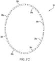
- FIGS. 7A-7C illustrate the skirt support 24 and internal support ring 32 coupled to an external support 38.
- the external support 38 comprises a plurality of arc-shaped segments 38a-h which together form a ring shape.
- the arc-shaped segments 38a-h engage a first face 24a of the skirt support 24, while the internal support ring 32 engages a second face 24b of the skirt support.
- the skirt support 24 is fixed between the internal support ring 32 and the external support 38.
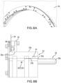
- FIG. 8A-8C show the guide assembly 23 engaged with the internal support ring 32, skirt support 24, and external support 38.
- the guide assembly 23 is a ring-shaped member having an outer surface 23a and an inner surface 23b.
- the outer surface 23a abuts an inner surface 32a of the internal support ring 32, while the inner surface 23b includes a plurality of grooves14 that guide the rotational movement of the valve disc assembly 26 via their interaction with projections 12.
- a plurality of rollers 40 are embedded in the inner surface 32a of the internal support ring 32. These rollers 40 are configured to engage the valve disc assembly 26 to facilitate a smooth rotation of the valve disc assembly.
- a spacer 25 is coupled to the guide assembly 23.
- the spacer 25 in the illustrated arrangement is a cylindrical member coupled at a first end 25a to the guide assembly 23.
- the second end 25b extends away from the guide assembly and is coupleable to a chimney support ( see FIG. 10B ).
- FIG. 8C shows the grooves 14 disposed in the inner surface 23b of the guide assembly 23. These grooves 14 interact with the associated projections 12 to hold the valve disc 11 in place and importantly to allow the valve disc assembly 26 to translate to release the engagement between the valve disc 11 and the seal 10 and to guide the valve disc assembly 26 as it rotates between the open and closed positions.
- one of the projections 12 of the valve disc assembly 26 is positioned within groove 14 in the inner surface 23b of the guide assembly 23.
- the valve disc assembly 26 is provided with four projections 12 positioned at 12, 3, 6 and 9 o'clock, respectively, on the valve disc assembly 26. Providing multiple projections 12 and a plurality of rollers 40 ( FIG. 8A ) ensures smooth rotation and axial movement of the valve disc assembly 26 with respect to guide assembly 23.
- FIGS. 10A-10C show chimney support 28 engaged with the spacer 25 of the guide assembly 23.
- the chimney support 28 is a circular member that holds the D-shaped flexible seal ring 10 which surrounds an opening 46 that is approximately the same shape and dimension of the opening 8 in the valve disc assembly 26.
- a D-shaped groove 48 is provided in the chimney support 28 surrounding the opening 46. The groove 48 receives and retains a portion of the flexible seal ring 10.
- the flexible seal ring 10 is glued to the groove 48.
- FIGS. 11A-11C the rotary disc valve 2 is shown in the closed position.
- the opening 8 in the disc 11 is positioned so that it does not align with the opening 48 in the chimney support 28.
- the seal ring 10 engages the solid portion 9 of the disc 11 so that no flow is allowed through the valve 2.
- the projection is positioned in the first end 13 of the groove 14 so the valve disc assembly 26 is held tight against the seal.
- FIGS. 12A-12C show the valve 2 as it is starting to move toward the open position.
- the pinion 20 of the motor 6 engages and rotates the teeth 22 of the gear parts 42 which rotates the valve disc assembly 26, including valve disc 11, toward the open position.
- the projection 12 slides within the angled portion 18 of the groove.
- the angled portion 18 of the groove forms an oblique angle ⁇ with respect to the longitudinal axis A-A of the valve 2 so that as the disc assembly 26 rotates, the projection 12 slides within the angled portion 18 of the groove and the disc assembly 26 moves in the direction of arrow "B".
- a component of its motion is parallel to the longitudinal axis A-A of the valve 2, which moves the disc assembly away from the chimney support 28 and the seal 10, thus decompressing the seal.
- FIGS. 13A-13C show the valve as the valve disc continues to rotate to the open position.
- the motor 6 continues to rotate the pinion 20, the teeth 22 of the gear parts 42 continue to rotate the valve disc assembly 26 toward the open position.
- the projection 12 exits the angled portion 18 of the groove 14 and enters the main portion of the groove, moving in the direction of arrow "C", which is oriented perpendicular to the longitudinal axis A-A of the valve.
- the valve disc 11 is offset from the seal 10 by a distance "D" ( FIG. 13C ). In one example embodiment this distance "D" is about 14 millimeters (mm).
- the valve disc assembly 26 rotates from the closed position toward the open position, the first projection 17a disengages the first sensor 31, and the valve disc assembly continues to rotate (via interaction with the pinion 20) until the second one of the projections 17b engages the second sensor 33.
- the switch assembly 30 signals the motor to stop rotating the pinion 20.
- the valve disc assembly 26 is rotated (again, via interaction with the pinion 20) toward the closed position such that the second projection 17b disengages the second sensor 33.
- the valve disc assembly continues to rotate until the first projection 17a engages the first sensor 31, whereupon the switch assembly 30 signals the motor to stop rotating the pinion 20.
- FIGS. 15A-15BC shows the relative positions of the motor and pinion and the external gearing when the valve is in the closed position ( FIG. 15A ) and the open position ( FIG. 15B ).
- the valve disc 11 In the closed position, the valve disc 11 is disposed directly adjacent to the chimney support 28 so the seal (not shown) engages the valve disc.
- the pinion 20 can be seen engaging a first lateral portion 22a of the teeth 22 of the gear parts.
- a recess 50 in the guide assembly 23 receives at least a portion of the pinion.
- valve disc 11 In the open position shown in FIG. 15B , the valve disc 11 is separated from the chimney support 28 by distance "D", which as previously mentioned can be about 14 mm. In this position the pinion engages a second lateral portion 22b of the teeth 22 of the gear parts.
- valve disc 11 movement of the valve disc 11 toward and away from the chimney support 28 does not affect the interaction between the pinion 20 and the teeth 22 of the gear parts, and the motor 6 and pinion 20 are able to engage and rotate the valve disc assembly 26 through the full range of motion of the valve disc 11 (from closed to open, then from open to closed).
- Connection references are to be construed broadly and may include intermediate members between a collection of elements and relative to movement between elements unless otherwise indicated. As such, connection references do not necessarily infer that two elements are directly connected and in fixed relation to each other. All rotational references describe relative movement between the various elements. Identification references (e.g., primary, secondary, first, second, third, fourth, etc.) are not intended to connote importance or priority but are used to distinguish one feature from another.
- the drawings are for purposes of illustration only and the dimensions, positions, order and relative to sizes reflected in the drawings attached hereto may vary.
Landscapes
- Engineering & Computer Science (AREA)
- General Engineering & Computer Science (AREA)
- Mechanical Engineering (AREA)
- Aviation & Aerospace Engineering (AREA)
- Lift Valve (AREA)
Description
- This is a Nonprovisional Patent Application of pending
U.S. Provisional Application Serial No. 63/439,909, filed January 19, 2023 - The present disclosure relates generally to rotary valves, and in particular to rotary valves for use in pressure relief applications.
- Various valve types are known and used in gas handling applications. Such valves include flap gate valves, butterfly valves, guillotine valves, ball valves, and the like. For applications in which the valves are used to relieve gas from a gas-containing structure, such as during pressure relief operations, these valve types suffer from a variety of disadvantages.
- For example, when such valve types are used in applications in which the valves need to relieve gas to an outdoor environment, outward facing flap valves can suffer from the disadvantage that the flap is subjected to the force of wind (which, for example, in high altitude applications can approach or exceed 100 km/h). In such cases the high wind forces can twist and/or damage the flap. Using an inwardly oriented flap in such applications would solve the problem of flap damage but would undesirably require a fluid passage diameter of three or more times larger than an outward facing flap valve. In either case, a large structure would be required to take up the overhang of the valve (assuming a translation of 200 mm or more), and the associated motor would be in the fluid flow path, which is not acceptable. Alternatively, a motor located away from the valve would involve a large overhang, which is also not acceptable. Such geometries also require a structure to withstand the operating forces, which increases the overall mass of the valve.
-
WO02013/073039A1 claim 1. - It would be advantageous to provide an improved valve for use in gas relief applications. Such a valve should address the above-noted deficiencies in conventional designs.
- This Summary is provided to introduce a selection of concepts in a simplified form that are further described below in the Detailed Description. This Summary is not intended to identify key features or essential features of the claimed subject matter, nor is it intended as an aid in determining the scope of the claimed subject matter.
- A rotary valve is disclosed for use in gas pressure relief applications. In one example embodiment the rotary valve is used to relieve internal helium pressures in an airship in the case of an overpressure condition within the helium-containing structure of the airship. In some embodiments the rotary valve is a safety valve used to relieve the pressure differential between internal helium pressure and the external ambient pressure as the airship rises.
- A rotary valve is disclosed in which frictional opening forces are eliminated during rotation of the valve. Such a rotary valve includes a rotary disc that is guided within the external valve support structure, and a docking ramp that causes an axial translation of the rotating disc to compress the rotary disc against a seal when the valve is in the closed position to ensure a gas-tight seal exists when the valve is in the closed position. In the opening phase, the kinematics of the ramp allow the rotary disc to be axially displaced away the seal so that the disc can be rotated to the open configuration (and then back to the closed configuration) without engaging the seal, thus eliminating friction between the two during cycling of the valve.
- Rotation of the rotary disc is obtained by the action of a motor that, via a pinion and worm connection, engages teeth on an outside surface of the rotary disc assembly. Axial translation of the rotary disc occurs by means of a radial guide groove formed in the valve housing, and within which one or more projections provided in the rotary disc assembly are received. The radial guide grooves are inclined at discrete locations (e.g., near the end of the rotational cycle) to axially move the rotary disc into and out of engagement with the valve seal.
- The groove/projection interaction thus induce a complex movement to the rotary disc. Thus, as the valve is being cycled from the closed configuration to the open configuration, the projections of the rotary disc assembly ride within an inclined portion of the groove, which thereby moves the rotary disc outward and decompresses the seal. The remainder of the valve movement to the fully open configuration is unimpeded by any frictional contact with the seal. by following the rotation and by contact with the profile of these grooves, the rotary disc is pushed outwards and decompresses the seal. A reverse movement transitions the rotary valve from the fully open configuration to the closed configuration.
- The arrangement of the rotary valve avoids wind entrapment and reduces aerodynamic stresses. The reduction in such stresses allows the mass of the rotary valve and any associated equipment to be reduced. Further, by locating the valve motor on the periphery of the valve, access for repairs is simplified, and the suspended mass associated with the valve is reduced.
- Additional advantages to the disclosed rotary valve include reduced size and weight, improved design and operation, more precise control, improved maintenance, and improved robustness, as compared to conventional designs.
- A rotary disc valve includes a guide assembly having a ring-shaped member with a groove disposed in an inner surface thereof, and a valve disc assembly rotatably coupled to the guide assembly. The valve disc assembly includes a valve disc, a projection received within the groove of the guide assembly, and a chimney support coupled to the guide assembly. The chimney support includes a seal member for selectively sealing against the valve disc. The groove has a main portion oriented perpendicular to a longitudinal axis of the rotary disc valve, and an angled portion oriented at an oblique angle with respect to the longitudinal axis.
- When the rotary disc valve is moved from a closed position toward an open position the valve disc assembly is rotated in a first direction with respect to the guide assembly, which moves the projection along the angled portion of the groove, thereby moving the valve disc away from the seal to decompress the seal. When the valve disc assembly is moved from the open position to the closed position the valve disc assembly is rotated in a second direction with respect to the guide assembly, which moves the projection along the angled portion of the groove, thereby moving the valve disc toward the seal to compress the seal.
- In some embodiments the angled portion of the groove is positioned adjacent to a first end of the groove. The main portion of the groove is positioned between the angled portion and a second end of the groove.
- When the rotary disc valve is in the closed position the seal engages the valve disc, and wherein when the rotary disc valve is in the open position the seal is disposed a distance "D" away from the valve disc. In some embodiments the distance "D" is about 14 millimeters.
- In some embodiments the rotary disc valve includes a skirt support coupled to the guide assembly, the skirt support configured to couple the rotary disc valve to surrounding structure.
- In some embodiments the rotary disc valve includes a chimney support coupled to the guide assembly, the chimney support having an open portion and a solid portion. When the valve is in the open position the open portion of the chimney support aligns with an open portion of the valve disc, and when the valve is in the closed position the open portion of the chimney support aligns with a solid portion of the valve disc. The open portion of the chimney support is D-shaped, and the seal is a D-shaped member coupled to the chimney support around the perimeter of the D-shaped open portion.
- In embodiments the rotary disc valve can include a motor coupled to the chimney support. The motor includes a rotatable pinion. The valve disc assembly includes a plurality of gear parts, each of the plurality of gear parts having external teeth for engaging the rotatable pinion so that when the motor turns in a first direction the pinion engages the teeth to move the valve disc assembly in a first direction to open the valve. When the motor turns in a second direction the pinion engages the teeth to move the valve disc assembly in a second direction to close the valve.
- In some embodiments the external teeth of the gear parts have first and second lateral portions. When the rotary disc valve is in the closed position the pinion engages the first lateral portions of the external teeth. When the rotary disc valve is in the open position the pinion engages the second lateral portions of the external teeth.
- In some embodiments the guide assembly includes a recess for receiving a portion of the pinion when the pinion is engaged with the first lateral portions of the external teeth. The rotary disc valve can include a sensor configured to sense a position of the valve disc assembly and for signaling the motor to stop rotating the pinion when the rotary disc valve is determined by the sensor to have moved from the closed position to the fully open position. The sensor can be configured to signal the motor to stop rotating the pinion when the rotary disc valve is determined by the sensor to have moved from the closed position to the fully open position.
- By way of example, a specific embodiment of the disclosed device will now be described, with reference to the accompanying drawings, in which:
-
FIG. 1 is a schematic view of an example airship for use with the disclosed valve; -
FIG. 2 is an isometric view of a rotary valve in accordance with the present disclosure installed in a portion of the airship ofFIG. 1 ; -
FIGS. 3A-3C are detail views of aspects of the rotary valve ofFIG. 2 ; -
FIG. 4 is an isolated isometric view of the rotary valve ofFIG. 2 ; -
FIG. 5 is an exploded view of the rotary valve ofFIG. 4 ; -
FIGS. 6A-6C are detail views of a skirt support portion of the rotary valve ofFIG. 4 ; -
FIGS. 7A-7C are detail views of the skirt support portions and external support ring of the rotary valve ofFIG. 4 ; -
FIGS. 8A-8C are detail views of a guiding portion with the external support ring and skirt support portion of the rotary valve ofFIG. 4 ; -
FIGS. 9A-9C are detail views of a gear portion with the guiding, external cerclage and skirt portions of the rotary valve ofFIG. 4 ; -
FIGS. 10A-10C are detail, cross-section and isometric views, respectively of the gear portion, guiding portion, external cerclage portion, and skirt portion, of the rotary valve ofFIG. 4 , coupled to a chimney support; -
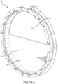
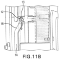
FIGS. 11A-11C are isometric, detail and cross-section views, respectively, of the rotary valve in the closed position of the rotary valve ofFIG. 4 ; -
FIGS. 12A-12C are isometric, detail and cross-section views, respectively, of the rotary valve ofFIG. 4 as the disc is translating for seal decompression; -
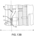
FIGS. 13A-13C are isometric, detail and cross-section views, respectively, of the rotary valve ofFIG. 4 as the valve disc is rotating; -
FIGS. 14A-14E are isometric and detail views of the rotary valve ofFIG. 4 in the open and closed positions; and -
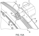
FIGS. 15A and15B are first and second isometric views of the motor and valve gear in the closed and open positions of the rotary valve ofFIG. 4 , respectively. - The drawings are not necessarily to scale. The drawings are merely representations, not intended to portray specific parameters of the disclosure. The drawings are intended to depict example embodiments of the disclosure, and therefore are not to be considered as limiting in scope. In the drawings, like numbering represents like elements.
- Numerous embodiments of an improved rotary valve in accordance with the present disclosure will now be described more fully hereinafter with reference to the accompanying drawings, in which preferred embodiments of the present disclosure are presented. The systems of the present disclosure may, however, be embodied in many different forms and should not be construed as being limited to the embodiments set forth herein. Rather, these embodiments are provided so that this disclosure will convey certain example aspects of rotary valves to those skilled in the art. In the drawings, like numbers refer to like elements throughout unless otherwise noted.
- This disclosure relates to rotary disc valves comprising a housing defining at least one passage for fluid to be controlled by the valve and a rotatable valve disc having an opening that can be brought into and out of alignment with a fluid flow passage through rotation of the disc within its own plane. The disclosure includes an arrangement in which the disc is axially shifted away from the seal as the valve is moved from the closed position to the open position to as to reduce or eliminate frictional forces associated with rotating the disc.
- Referring now to
FIG. 1 , anexample airship 1 is shown incorporating a plurality ofrotary disc valves 2 according to the disclosure. As previously mentioned, therotary disc valves 2 are used to relieve internal helium pressure in theairship 1 as the airship ascends and ambient pressures decrease. To adjust the pressure differential between the helium within theairship 1 and the ambient air as the airship ascends, a control system (not shown) opens one or more of therotary disc valves 2 to allow helium to be discharged to the atmosphere. The control system then closes therotary disc valves 2 when a desired reduced helium pressure within the airship is achieved. -
FIG. 2 illustrates therotary disc valve 2 and related supportingstructure 4, along withmotor 6 which can be seen positioned at a periphery of the valve. Therotary disc valve 2 is shown in the open configuration such that anopening 8 in the disc is aligned to allow flow through the valve. -
FIGS. 3A - 3C show various details of therotary disc valve 2 shown inFIG. 2 . Specifically,FIG. 3A shows the position ofseal 10 which seals between the supporting structure 4 (which in one embodiment is chimney support 28 - seeFIG. 10C ) and thevalve disc 11.FIG. 3B shows theprojection 12 associated with thevalve disc 11 positioned withingroove 14 associated with thevalve body 16. As will be described in greater detail later, as thevalve disc 1 rotates, theprojection 12 rides within theangled portion 18 of thegroove 14, and theprojection 12 andvalve disc 11 move axially with respect to thevalve body 16 and theseal 10. This axial movement serves to decompress the seal and allows thevalve disc 11 to rotate unimpeded by frictional forces associated with engagement between thevalve disc 11 and theseal 10.FIG. 3C shows the interengagement between apinion 20 of themotor 6 andexternal gear teeth 22 disposed on a periphery of the valve disc assembly. -
FIGS. 4 and5 shows therotary disc valve 2 includingguide assembly 23 andskirt support 24,valve disc assembly 26, andchimney support 28.Motor 6 is shown coupled to thechimney support 28 such thatpinion 20 engagesgear teeth 22 on the periphery of thevalve disc assembly 26. Switch assembly 30 (the function of which will be described in greater detail later) is also shown coupled to thechimney support 28. -
FIGS. 6A-6C illustrate aspects of theskirt support 24 and associatedinternal support ring 32. Theskirt support 24 has a solid ring-shapedprojection portion 34 which engages arecess 36 formed in theinner support ring 32 to hold the two together. Theinner support ring 32 is shown as formed from a series of arc-shaped segments coupled together to form the ring. Theskirt support 24 also serves as a mechanical interface with support structure associated with theairship 1 -
FIGS. 7A-7C illustrate theskirt support 24 andinternal support ring 32 coupled to anexternal support 38. As can be seen, theexternal support 38 comprises a plurality of arc-shapedsegments 38a-h which together form a ring shape. The arc-shapedsegments 38a-h engage afirst face 24a of theskirt support 24, while theinternal support ring 32 engages asecond face 24b of the skirt support. Thus arranged, theskirt support 24 is fixed between theinternal support ring 32 and theexternal support 38. -
FIG. 8A-8C show theguide assembly 23 engaged with theinternal support ring 32,skirt support 24, andexternal support 38. Theguide assembly 23 is a ring-shaped member having anouter surface 23a and aninner surface 23b. Theouter surface 23a abuts aninner surface 32a of theinternal support ring 32, while theinner surface 23b includes a plurality of grooves14 that guide the rotational movement of thevalve disc assembly 26 via their interaction withprojections 12. A plurality ofrollers 40 are embedded in theinner surface 32a of theinternal support ring 32. Theserollers 40 are configured to engage thevalve disc assembly 26 to facilitate a smooth rotation of the valve disc assembly. Aspacer 25 is coupled to theguide assembly 23. Thespacer 25 in the illustrated arrangement is a cylindrical member coupled at afirst end 25a to theguide assembly 23. Thesecond end 25b extends away from the guide assembly and is coupleable to a chimney support (seeFIG. 10B ).FIG. 8C shows thegrooves 14 disposed in theinner surface 23b of theguide assembly 23. Thesegrooves 14 interact with the associatedprojections 12 to hold thevalve disc 11 in place and importantly to allow thevalve disc assembly 26 to translate to release the engagement between thevalve disc 11 and theseal 10 and to guide thevalve disc assembly 26 as it rotates between the open and closed positions. -
FIGS. 9A-9C show thevalve disc assembly 26 engaged with theguide assembly 23 engaged with theinternal support ring 32,skirt support 24, andexternal support 38. As can be seen, thevalve disc assembly 26 includes a plurality ofgear parts 42 coupled together to form a ring-shaped element, and avalve disc 11 having anopening 8 in one half. Each of the plurality ofgear parts 42 includes anouter surface 44 that includes, on at least a portion thereof,gear teeth 22. As previously described, thepinion 20 of themotor 6 engages thegear teeth 22 of thevalve disc assembly 26 such that rotation of the pinion rotates thevalve disc assembly 26 in a desired direction. - As best seen in
FIG. 9B , one of theprojections 12 of thevalve disc assembly 26 is positioned withingroove 14 in theinner surface 23b of theguide assembly 23. As can be seen inFIG. 9C , thevalve disc assembly 26 is provided with fourprojections 12 positioned at 12, 3, 6 and 9 o'clock, respectively, on thevalve disc assembly 26. Providingmultiple projections 12 and a plurality of rollers 40 (FIG. 8A ) ensures smooth rotation and axial movement of thevalve disc assembly 26 with respect to guideassembly 23. -
FIGS. 10A-10C show chimney support 28 engaged with thespacer 25 of theguide assembly 23. Thechimney support 28 is a circular member that holds the D-shapedflexible seal ring 10 which surrounds anopening 46 that is approximately the same shape and dimension of theopening 8 in thevalve disc assembly 26. To receive theflexible seal ring 10, a D-shapedgroove 48 is provided in thechimney support 28 surrounding theopening 46. Thegroove 48 receives and retains a portion of theflexible seal ring 10. In some embodiments theflexible seal ring 10 is glued to thegroove 48. - Referring now to
FIGS. 11A-11C therotary disc valve 2 is shown in the closed position. In the closed position theopening 8 in thedisc 11 is positioned so that it does not align with theopening 48 in thechimney support 28. As can be seen inFIG. 11C , theseal ring 10 engages thesolid portion 9 of thedisc 11 so that no flow is allowed through thevalve 2. As shown inFIG. 11B , the projection is positioned in thefirst end 13 of thegroove 14 so thevalve disc assembly 26 is held tight against the seal. -
FIGS. 12A-12C show thevalve 2 as it is starting to move toward the open position. Thepinion 20 of themotor 6 engages and rotates theteeth 22 of thegear parts 42 which rotates thevalve disc assembly 26, includingvalve disc 11, toward the open position. Theprojection 12 slides within theangled portion 18 of the groove. Theangled portion 18 of the groove forms an oblique angle β with respect to the longitudinal axis A-A of thevalve 2 so that as thedisc assembly 26 rotates, theprojection 12 slides within theangled portion 18 of the groove and thedisc assembly 26 moves in the direction of arrow "B". As will be appreciated, as thedisc assembly 26 rotates, a component of its motion is parallel to the longitudinal axis A-A of thevalve 2, which moves the disc assembly away from thechimney support 28 and theseal 10, thus decompressing the seal. -
FIGS. 13A-13C show the valve as the valve disc continues to rotate to the open position. As themotor 6 continues to rotate thepinion 20, theteeth 22 of thegear parts 42 continue to rotate thevalve disc assembly 26 toward the open position. As can be seen, theprojection 12 exits theangled portion 18 of thegroove 14 and enters the main portion of the groove, moving in the direction of arrow "C", which is oriented perpendicular to the longitudinal axis A-A of the valve. In this position thevalve disc 11 is offset from theseal 10 by a distance "D" (FIG. 13C ). In one example embodiment this distance "D" is about 14 millimeters (mm). - Rotation continues until the
opening 8 in thedisc 11 begin aligns with theopening 46 in thechimney support 28, as shown inFIGS. 14A-14C . Thevalve disc 11 includes a pair of radially extendingprojections 17a, b disposed on opposite sides of the disc (seeFIG. 14C ) and are configured to interact with first andsecond sensors 31, 33 (seeFIGS. 14D-E ) of theswitch assembly 30. In the closed position a first one of theprojections 17a is engaged with thefirst sensor 31. - Referring to
FIGS. 14D-E , as thevalve disc assembly 26 rotates from the closed position toward the open position, thefirst projection 17a disengages thefirst sensor 31, and the valve disc assembly continues to rotate (via interaction with the pinion 20) until the second one of theprojections 17b engages the second sensor 33. Theswitch assembly 30 signals the motor to stop rotating thepinion 20. Thus, in the open position thesecond projection 17b is engaged with the second sensor 33. To close the valve, thevalve disc assembly 26 is rotated (again, via interaction with the pinion 20) toward the closed position such that thesecond projection 17b disengages the second sensor 33. The valve disc assembly continues to rotate until thefirst projection 17a engages thefirst sensor 31, whereupon theswitch assembly 30 signals the motor to stop rotating thepinion 20. - In the illustrated closed position, the
projection 12 is received within thesecond end 15 of thegroove 14. As will be appreciated, grooves 14 (two positioned at 180° and two others at 90° offset by, for example, 14 mm) are provided in theguide assembly 23, one associated with each of the twoprojections 12 provided in thevalve disc assembly 26. - FIGS. 15A-15BC shows the relative positions of the motor and pinion and the external gearing when the valve is in the closed position (
FIG. 15A ) and the open position (FIG. 15B ). In the closed position, thevalve disc 11 is disposed directly adjacent to thechimney support 28 so the seal (not shown) engages the valve disc. Thepinion 20 can be seen engaging a firstlateral portion 22a of theteeth 22 of the gear parts. Arecess 50 in theguide assembly 23 receives at least a portion of the pinion. - In the open position shown in
FIG. 15B , thevalve disc 11 is separated from thechimney support 28 by distance "D", which as previously mentioned can be about 14 mm. In this position the pinion engages a secondlateral portion 22b of theteeth 22 of the gear parts. - Thus, with the disclosed arrangement, movement of the
valve disc 11 toward and away from thechimney support 28 does not affect the interaction between thepinion 20 and theteeth 22 of the gear parts, and themotor 6 andpinion 20 are able to engage and rotate thevalve disc assembly 26 through the full range of motion of the valve disc 11 (from closed to open, then from open to closed). - While the present disclosure refers to certain embodiments, numerous modifications, alterations, and changes to the described embodiments are possible without departing from the sphere and scope of the present disclosure, as defined in the appended claim(s). Accordingly, it is intended that the present disclosure not be limited to the described embodiments, but that it has the full scope defined by the language of the following claims, and equivalents thereof. The discussion of any embodiment is meant only to be explanatory and is not intended to suggest that the scope of the disclosure, including the claims, is limited to these embodiments. In other words, while illustrative embodiments of the disclosure have been described in detail herein, it is to be understood that the inventive concepts may be otherwise variously embodied and employed, and that the appended claims are intended to be construed to include such variations, except as limited by the prior art.
- The foregoing discussion has been presented for purposes of illustration and description and is not intended to limit the disclosure to the form or forms disclosed herein. For example, various features of the disclosure are grouped together in one or more aspects, embodiments, or configurations for the purpose of streamlining the disclosure. However, it should be understood that various features of the certain aspects, embodiments, or configurations of the disclosure may be combined in alternate aspects, embodiments, or configurations.
- As used herein, an element or step recited in the singular and proceeded with the word "a" or "an" should be understood as not excluding plural elements or steps, unless such exclusion is explicitly recited. Furthermore, references to "one embodiment" of the present disclosure are not intended to be interpreted as excluding the existence of additional embodiments that also incorporate the recited features.
- The phrases "at least one", "one or more", and "and/or", as used herein, are open-ended expressions that are both conjunctive and disjunctive in operation. The terms "a" (or "an"), "one or more" and "at least one" can be used interchangeably herein. All directional references (e.g., proximal, distal, upper, lower, upward, downward, left, right, lateral, longitudinal, front, back, top, bottom, above, below, vertical, horizontal, radial, axial, clockwise, and counterclockwise) are only used for identification purposes to aid the reader's understanding of the present disclosure, and do not create limitations, particularly as to the position, orientation, or use of this disclosure. Connection references (e.g., engaged, attached, coupled, connected, and joined) are to be construed broadly and may include intermediate members between a collection of elements and relative to movement between elements unless otherwise indicated. As such, connection references do not necessarily infer that two elements are directly connected and in fixed relation to each other. All rotational references describe relative movement between the various elements. Identification references (e.g., primary, secondary, first, second, third, fourth, etc.) are not intended to connote importance or priority but are used to distinguish one feature from another. The drawings are for purposes of illustration only and the dimensions, positions, order and relative to sizes reflected in the drawings attached hereto may vary.
Claims (15)
- A rotary disc valve (2), comprising:a guide assembly (23) comprising a ring-shaped member having a groove (14) disposed in an inner surface (23b) thereof;a valve disc assembly (26) rotatably coupled to the guide assembly, the valve disc assembly comprising:a valve disc (11),a projection (12) received within the groove of the guide assembly; anda chimney support (28) coupled to the guide assembly, the chimney support including a seal member (10) for selectively sealing against the valve disc;wherein the groove (14) has a main portion oriented perpendicular to a longitudinal axis of the rotary disc valve, and an angled portion (18) oriented at an oblique angle with respect to the longitudinal axis; andwherein when the rotary disc valve is moved from a closed position toward an open position the valve disc assembly is rotated in a first direction with respect to the guide assembly, which moves the projection along the angled portion of the groove, thereby moving the valve disc away from the seal to decompress the seal; andwherein when the valve disc assembly is moved from the open position to the closed position the valve disc assembly is rotated in a second direction with respect to the guide assembly, which moves the projection along the angled portion of the groove, thereby moving the valve disc toward the seal to compress the seal.
- The rotary disc valve of claim 1, wherein the angled portion (18) of the groove is positioned adjacent to a first end (13) of the groove.
- The rotary disc valve of claim 2, wherein the main portion of the groove is positioned between the angled portion and a second end (15) of the groove.
- The rotary disc valve of claim 1, wherein when the rotary disc valve is in the closed position the seal engages the valve disc, and wherein when the rotary disc valve is in the open position the seal is disposed a distance "D" away from the valve disc.
- The rotary disc valve of claim 4, wherein the distance "D" is about 14 millimeters.
- The rotary disc valve of claim 1, further comprising a skirt support (24) coupled to the guide assembly (23), the skirt support configured to couple the rotary disc valve to surrounding structure.
- The rotary disc valve of claim 1, the chimney support having an open portion and a solid portion, wherein when the valve is in the open position the open portion of the chimney support aligns with an open portion of the valve disc, and wherein when the valve is in the closed position the open portion (46) of the chimney support aligns with a solid portion of the valve disc.
- The rotary disc valve of claim 7, wherein the open portion (46) of the chimney support is D-shaped, and wherein the seal is a D-shaped member coupled to the chimney support around the perimeter of the D-shaped open portion.
- The rotary disc valve of claim 1, further comprising a motor (6) coupled to the chimney support, the motor including a rotatable pinion (20), the valve disc assembly comprising a plurality of gear parts, each of the plurality of gear parts having external teeth (22) for engaging the rotatable pinion so that when the motor turns in a first direction the pinion engages the teeth to move the valve disc assembly in a first direction to open the valve, and when the motor turns in a second direction the pinion engages the teeth to move the valve disc assembly in a second direction to close the valve.
- The rotary disc valve of claim 9, wherein the external teeth of the gear parts comprise first (22a) and second (22b) lateral portions, and wherein when the rotary disc valve is in the closed position the pinion engages the first lateral portions of the external teeth, and wherein when the rotary disc valve is in the open position the pinion engages the second lateral portions of the external teeth.
- The rotary disc valve of claim 10, wherein the guide assembly includes a recess for receiving a portion of the pinion when the pinion is engaged with the first lateral portions of the external teeth.
- The rotary disc valve of claim 1, further comprising a sensor (31, 33) configured to sense a position of the valve disc assembly and for signaling the motor to stop rotating the pinion when the rotary disc valve is determined by the sensor to have moved from the closed position to the fully open position.
- The rotary disc valve of claim 12, wherein the sensor is further configured to signal the motor to stop rotating the pinion when the rotary disc valve is determined by the sensor to have moved from the closed position to the fully open position.
- An airship including a plurality of rotary disc valves according to claim 1.
- The use of a rotary disc valve according to claim 1 as a safety pressure relief valve.
Applications Claiming Priority (1)
| Application Number | Priority Date | Filing Date | Title |
|---|---|---|---|
| US202363439909P | 2023-01-19 | 2023-01-19 |
Publications (3)
| Publication Number | Publication Date |
|---|---|
| EP4403804A1 EP4403804A1 (en) | 2024-07-24 |
| EP4403804B1 true EP4403804B1 (en) | 2025-05-07 |
| EP4403804C0 EP4403804C0 (en) | 2025-05-07 |
Family
ID=89619581
Family Applications (1)
| Application Number | Title | Priority Date | Filing Date |
|---|---|---|---|
| EP24151854.7A Active EP4403804B1 (en) | 2023-01-19 | 2024-01-15 | Rotary disc valve |
Country Status (2)
| Country | Link |
|---|---|
| US (1) | US12320440B2 (en) |
| EP (1) | EP4403804B1 (en) |
Family Cites Families (5)
| Publication number | Priority date | Publication date | Assignee | Title |
|---|---|---|---|---|
| GB706371A (en) | 1952-01-18 | 1954-03-31 | Glover & Co Ltd W T | Improvements in the manufacture of insulated electric conductors |
| GB874169A (en) | 1958-07-24 | 1961-08-02 | Koppers Gmbh Heinrich | Improvements relating to rotary disc valves |
| DE58905222D1 (en) | 1988-06-03 | 1993-09-16 | Zeppelin Schuettguttech Gmbh | SEAL ARRANGEMENT. |
| WO2013073039A1 (en) | 2011-11-17 | 2013-05-23 | プログレッシオ合同会社 | Gate valve for vacuum |
| EP3159587A1 (en) | 2015-02-16 | 2017-04-26 | King Lai Hygienic Materials Co., Ltd. | Gate valve with secure sealing mechanism |
-
2024
- 2024-01-05 US US18/405,167 patent/US12320440B2/en active Active
- 2024-01-15 EP EP24151854.7A patent/EP4403804B1/en active Active
Also Published As
| Publication number | Publication date |
|---|---|
| EP4403804A1 (en) | 2024-07-24 |
| US20240247724A1 (en) | 2024-07-25 |
| US12320440B2 (en) | 2025-06-03 |
| EP4403804C0 (en) | 2025-05-07 |
Similar Documents
| Publication | Publication Date | Title |
|---|---|---|
| US9506571B1 (en) | Cryogenic cam butterfly valve | |
| CA1105438A (en) | Sealing ring | |
| US9279505B2 (en) | Valve core assembly and valve adopting the valve core assembly | |
| US4394022A (en) | Mechanically expandable annular seal | |
| US4554948A (en) | Straight-way valve | |
| US3109623A (en) | Valve construction having resilient sealing means | |
| CA1122188A (en) | Fluid control valve and method | |
| CA1192177A (en) | Valve assembly and seat | |
| US4569365A (en) | Device for detecting the operation of a valve | |
| WO2016052372A1 (en) | Flow rate control device and vehicle | |
| EP4403804A1 (en) | Rotary disc valve | |
| US4024890A (en) | Rotary valve | |
| US5609185A (en) | Valve indicator and handle assembly | |
| CA2550524C (en) | Coaxial valve | |
| EP3338012B1 (en) | Axial-seal butterfly valves | |
| CN217977405U (en) | Blanking valve | |
| CN113586748A (en) | Valve capable of quantitatively adjusting fluid flow and adjusting method thereof | |
| US4150694A (en) | Rotary plug valve | |
| EP0551724B1 (en) | Actuator for a rotary valve | |
| CN118912229B (en) | Pressure balance type low-torque sealing ball valve | |
| US20240410474A1 (en) | Ball valve, in particular for explosion isolation in process pipelines | |
| CN216590127U (en) | Spring type pressure stabilizer safety valve | |
| US5029809A (en) | Valve-control device and valve having such a control device | |
| CN114909516B (en) | A pressure relief device for a hydrogenation reactor | |
| US4482128A (en) | High pressure cam seal valve |
Legal Events
| Date | Code | Title | Description |
|---|---|---|---|
| PUAI | Public reference made under article 153(3) epc to a published international application that has entered the european phase |
Free format text: ORIGINAL CODE: 0009012 |
|
| STAA | Information on the status of an ep patent application or granted ep patent |
Free format text: STATUS: THE APPLICATION HAS BEEN PUBLISHED |
|
| AK | Designated contracting states |
Kind code of ref document: A1 Designated state(s): AL AT BE BG CH CY CZ DE DK EE ES FI FR GB GR HR HU IE IS IT LI LT LU LV MC ME MK MT NL NO PL PT RO RS SE SI SK SM TR |
|
| STAA | Information on the status of an ep patent application or granted ep patent |
Free format text: STATUS: REQUEST FOR EXAMINATION WAS MADE |
|
| 17P | Request for examination filed |
Effective date: 20240908 |
|
| RBV | Designated contracting states (corrected) |
Designated state(s): AL AT BE BG CH CY CZ DE DK EE ES FI FR GB GR HR HU IE IS IT LI LT LU LV MC ME MK MT NL NO PL PT RO RS SE SI SK SM TR |
|
| GRAP | Despatch of communication of intention to grant a patent |
Free format text: ORIGINAL CODE: EPIDOSNIGR1 |
|
| STAA | Information on the status of an ep patent application or granted ep patent |
Free format text: STATUS: GRANT OF PATENT IS INTENDED |
|
| RIC1 | Information provided on ipc code assigned before grant |
Ipc: B64B 1/00 20060101ALI20241219BHEP Ipc: B64B 1/64 20060101ALI20241219BHEP Ipc: F16K 31/53 20060101ALI20241219BHEP Ipc: F16K 31/524 20060101ALI20241219BHEP Ipc: F16K 3/10 20060101ALI20241219BHEP Ipc: F16K 3/08 20060101AFI20241219BHEP |
|
| INTG | Intention to grant announced |
Effective date: 20250114 |
|
| GRAS | Grant fee paid |
Free format text: ORIGINAL CODE: EPIDOSNIGR3 |
|
| GRAA | (expected) grant |
Free format text: ORIGINAL CODE: 0009210 |
|
| STAA | Information on the status of an ep patent application or granted ep patent |
Free format text: STATUS: THE PATENT HAS BEEN GRANTED |
|
| AK | Designated contracting states |
Kind code of ref document: B1 Designated state(s): AL AT BE BG CH CY CZ DE DK EE ES FI FR GB GR HR HU IE IS IT LI LT LU LV MC ME MK MT NL NO PL PT RO RS SE SI SK SM TR |
|
| REG | Reference to a national code |
Ref country code: GB Ref legal event code: FG4D |
|
| REG | Reference to a national code |
Ref country code: CH Ref legal event code: EP |
|
| REG | Reference to a national code |
Ref country code: DE Ref legal event code: R096 Ref document number: 602024000095 Country of ref document: DE |
|
| REG | Reference to a national code |
Ref country code: IE Ref legal event code: FG4D |
|
| U01 | Request for unitary effect filed |
Effective date: 20250523 |
|
| U07 | Unitary effect registered |
Designated state(s): AT BE BG DE DK EE FI FR IT LT LU LV MT NL PT RO SE SI Effective date: 20250603 |
|
| PG25 | Lapsed in a contracting state [announced via postgrant information from national office to epo] |
Ref country code: ES Free format text: LAPSE BECAUSE OF FAILURE TO SUBMIT A TRANSLATION OF THE DESCRIPTION OR TO PAY THE FEE WITHIN THE PRESCRIBED TIME-LIMIT Effective date: 20250507 |
|
| PG25 | Lapsed in a contracting state [announced via postgrant information from national office to epo] |
Ref country code: NO Free format text: LAPSE BECAUSE OF FAILURE TO SUBMIT A TRANSLATION OF THE DESCRIPTION OR TO PAY THE FEE WITHIN THE PRESCRIBED TIME-LIMIT Effective date: 20250807 Ref country code: GR Free format text: LAPSE BECAUSE OF FAILURE TO SUBMIT A TRANSLATION OF THE DESCRIPTION OR TO PAY THE FEE WITHIN THE PRESCRIBED TIME-LIMIT Effective date: 20250808 |
|
| PG25 | Lapsed in a contracting state [announced via postgrant information from national office to epo] |
Ref country code: PL Free format text: LAPSE BECAUSE OF FAILURE TO SUBMIT A TRANSLATION OF THE DESCRIPTION OR TO PAY THE FEE WITHIN THE PRESCRIBED TIME-LIMIT Effective date: 20250507 |
|
| PG25 | Lapsed in a contracting state [announced via postgrant information from national office to epo] |
Ref country code: HR Free format text: LAPSE BECAUSE OF FAILURE TO SUBMIT A TRANSLATION OF THE DESCRIPTION OR TO PAY THE FEE WITHIN THE PRESCRIBED TIME-LIMIT Effective date: 20250507 |
|
| PG25 | Lapsed in a contracting state [announced via postgrant information from national office to epo] |
Ref country code: RS Free format text: LAPSE BECAUSE OF FAILURE TO SUBMIT A TRANSLATION OF THE DESCRIPTION OR TO PAY THE FEE WITHIN THE PRESCRIBED TIME-LIMIT Effective date: 20250807 |
|
| PG25 | Lapsed in a contracting state [announced via postgrant information from national office to epo] |
Ref country code: IS Free format text: LAPSE BECAUSE OF FAILURE TO SUBMIT A TRANSLATION OF THE DESCRIPTION OR TO PAY THE FEE WITHIN THE PRESCRIBED TIME-LIMIT Effective date: 20250907 |
|
| PG25 | Lapsed in a contracting state [announced via postgrant information from national office to epo] |
Ref country code: SM Free format text: LAPSE BECAUSE OF FAILURE TO SUBMIT A TRANSLATION OF THE DESCRIPTION OR TO PAY THE FEE WITHIN THE PRESCRIBED TIME-LIMIT Effective date: 20250507 |
|
| U20 | Renewal fee for the european patent with unitary effect paid |
Year of fee payment: 3 Effective date: 20251205 |
|
| PG25 | Lapsed in a contracting state [announced via postgrant information from national office to epo] |
Ref country code: CZ Free format text: LAPSE BECAUSE OF FAILURE TO SUBMIT A TRANSLATION OF THE DESCRIPTION OR TO PAY THE FEE WITHIN THE PRESCRIBED TIME-LIMIT Effective date: 20250507 |
|
| PG25 | Lapsed in a contracting state [announced via postgrant information from national office to epo] |
Ref country code: SK Free format text: LAPSE BECAUSE OF FAILURE TO SUBMIT A TRANSLATION OF THE DESCRIPTION OR TO PAY THE FEE WITHIN THE PRESCRIBED TIME-LIMIT Effective date: 20250507 |
|
| PLBE | No opposition filed within time limit |
Free format text: ORIGINAL CODE: 0009261 |
|
| STAA | Information on the status of an ep patent application or granted ep patent |
Free format text: STATUS: NO OPPOSITION FILED WITHIN TIME LIMIT |
|
| REG | Reference to a national code |
Ref country code: CH Ref legal event code: L10 Free format text: ST27 STATUS EVENT CODE: U-0-0-L10-L00 (AS PROVIDED BY THE NATIONAL OFFICE) Effective date: 20260318 |
|
| 26N | No opposition filed |
Effective date: 20260210 |