EP4403799A1 - Schwerkraft verwendende drehvorrichtung - Google Patents
Schwerkraft verwendende drehvorrichtung Download PDFInfo
- Publication number
- EP4403799A1 EP4403799A1 EP22869925.2A EP22869925A EP4403799A1 EP 4403799 A1 EP4403799 A1 EP 4403799A1 EP 22869925 A EP22869925 A EP 22869925A EP 4403799 A1 EP4403799 A1 EP 4403799A1
- Authority
- EP
- European Patent Office
- Prior art keywords
- rotation
- rotation body
- weight
- force receiving
- main
- Prior art date
- Legal status (The legal status is an assumption and is not a legal conclusion. Google has not performed a legal analysis and makes no representation as to the accuracy of the status listed.)
- Pending
Links
Images










Classifications
-
- F—MECHANICAL ENGINEERING; LIGHTING; HEATING; WEAPONS; BLASTING
- F03—MACHINES OR ENGINES FOR LIQUIDS; WIND, SPRING, OR WEIGHT MOTORS; PRODUCING MECHANICAL POWER OR A REACTIVE PROPULSIVE THRUST, NOT OTHERWISE PROVIDED FOR
- F03G—SPRING, WEIGHT, INERTIA OR LIKE MOTORS; MECHANICAL-POWER PRODUCING DEVICES OR MECHANISMS, NOT OTHERWISE PROVIDED FOR OR USING ENERGY SOURCES NOT OTHERWISE PROVIDED FOR
- F03G3/00—Other motors, e.g. gravity or inertia motors
- F03G3/087—Gravity or weight motors
- F03G3/091—Gravity or weight motors using unbalanced wheels
Definitions
- the present invention relates to a rotation device utilizing gravity. More particularly, the invention relates to a device capable of rotating a rotation body with a small power by utilizing gravity.
- Patent Literature 1 a method for always obtaining power stably and permanently by connecting a tail end of a holding bar with a weight fixed to a tip end to a spur gear via a bearing on a driving wheel to make the holding bar rotatable, installing several holding bars horizontally and in a fixed direction, causing the driving wheel to generate a rotation motion by applying heavy pressure to only one side of the vertical driving wheel, that is, a method for obtaining power by a descending pressure of the weight attached to the driving wheel" (the claims of Patent Literature 1) has been known.
- the power generation device has an object “to provide a power generation device that enables connection with equipment using rotation as a power source by converting gravity into a rotation force” as described in the summary section of the same literature, and, as the solution, has “the power generation device that converts gravity into a rotation force, and utilizes the converted power as the power source, and includes a mechanism that creates an imbalance by not balancing gravity, with respect to the law of nature that tries to balance gravity, and generates a rotation force that creates energy of rotation in the imbalance”.
- positions of a plurality of mass points m attached to the rotation body D are positioned (positioned in a horizontal state, for example) so that the moment (torque) acting on the rotation body D is always positive, and thereby the rotation body D is rotated.
- the problem is how to position the positions of the plurality of mass points m attached to the rotation body D so that the moment (torque) acting on the rotation body D is always positive.
- An object of the present invention is to solve the above-described problems and provide a rotation device utilizing gravity capable of rotating a rotation body by utilizing gravity by positioning the positions of a plurality of mass points attached to the rotation body so that moment (torque) acting on the rotation body is always positive.
- a rotation device utilizing gravity of the present invention includes
- the plurality of weight holding mechanisms each provided at the installation position on the main rotation body, separated by the rotation radius R from the rotation center O of the main rotation body mounted rotatably around the horizontal axis with respect to the base body, and equiangularly spaced from one another with respect to the rotation center O each includes the weight body, the weight body is turnably supported at the support portion other than the rotation center of the weight support rotation body with respect to the weight support rotation body provided rotatably around the horizontal axis with respect to the aforementioned main rotation body in the aforementioned installation position and tries to turn the weight body itself in the same direction as the aforementioned main rotation body, and the turning force is transmitted to the turning force receiving member provided to be turnable concentrically with the rotation center of the aforementioned weight support rotation body at the first turning force receiving position to try to turn the turning force receiving member, and further transmitted to the force receiving rotation body provided to be rotatable concentrically with the rotation center of the aforementioned weight support rotation body at the second turning force receiving position to try to turn the force receiving
- the power applying mechanism applies the power that rotates the force receiving rotation body at the same angular velocity as the main rotation body in the opposite direction to the rotation direction of the aforementioned main rotation body to the force receiving rotation body in at least one weight holding mechanism of the plurality of weight holding mechanisms, and therefore, the device can continue to operate by this power.
- the support portion of the weight body in the aforementioned weight support rotation body is provided at the position where the reaction force from the aforementioned turning force receiving member does not rotate the weight support rotation body in the same direction as the rotation direction of the aforementioned main rotation body (the rotation force to rotate the weight support rotation body in the opposite direction is generated, for example), the rotation of the weight support rotation body in the opposite direction to the rotation direction of the main rotation body is not hindered by providing the weight body, and since when the distance from the rotation center in the aforementioned force receiving rotation body to the first turning force receiving position is L1, and the distance from the rotation center to the second turning force receiving position is L2, L1 and L2 are configured to satisfy L1 ⁇ L2, it is possible to decrease the power that rotates the force receiving rotation body in the weight holding mechanism at the same angular velocity as the main rotation body in the opposite direction to the rotation direction of the aforementioned main rotation body.
- the power applying mechanism can be provided for at least one weight holding mechanism, and for the other weight holding mechanisms, the force receiving rotation bodies can be interlocked with the rotation of the aforementioned main rotation body to rotate at the same angular velocity as the main rotation body in the opposite direction to the rotation direction of the main rotation body by the force receiving rotation body interlocking mechanisms, the power by the above-described power applying mechanism can be decreased.
- the rotation device utilizing gravity of the present invention it is possible to rotate the rotation body by utilizing gravity by positioning the positions of the mass points by the plurality of weight bodies attached to the rotation body so that the moment (torque) acting on the rotation body is always positive with the small power by the power applying mechanism.
- a rotation device utilizing gravity of the present invention includes
- the plurality of weight holding mechanisms each provided at the installation position on the main rotation body, separated by the rotation radius R from the rotation center O of the main rotation body mounted rotatably around the horizontal axis with respect to the base body, and equiangularly spaced from one another with respect to the rotation center O each includes the weight body, the weight body is turnably supported at the support portion other than the rotation center of the weight support rotation body with respect to the weight support rotation body provided rotatably around the horizontal axis with respect to the aforementioned main rotation body in the aforementioned installation position and tries to turn the weight body itself in the same direction as the aforementioned main rotation body, and the turning force is transmitted to the force receiving rotation body provided to be turnable concentrically with the rotation center of the aforementioned weight support rotation body at the power receiving position to try to turn the force receiving rotation body.
- the power applying mechanism applies the power that rotates the force receiving rotation body at the same angular velocity as the main rotation body in the opposite direction to the rotation direction of the main rotation body to the force receiving rotation body in at least one weight holding mechanism of the plurality of weight holding mechanisms, so that the device can be continued to operate by this power.
- the support portion of the weight body in the aforementioned weight support rotation body is provided at the position where the reaction force from the aforementioned force receiving rotation body does not tries to rotate the weight support rotation body in the same direction as the rotation direction of the aforementioned main rotation body (the rotation force to rotate the weight support rotation body in the opposite direction is generated, for example), the rotation of the weight support rotation body in the opposite direction to the rotation direction of the main rotation body is not hindered by providing the weight body, and since the power applying mechanism can be provided for at least one weight holding mechanism, and for the other weight holding mechanisms, the force receiving rotation bodies can be interlocked with the rotation of the aforementioned main rotation body to be rotated at the same angular velocity as the main rotation body in the opposite direction to the rotation direction of the main rotation body by the force receiving rotation body interlocking mechanisms, the power by the above-described power applying mechanism can be decreased.
- the rotation device utilizing gravity of the present invention it is possible to rotate the rotation body by utilizing gravity by positioning the positions of the mass points by the plurality of weight bodies attached to the rotation body so that the moment (torque) acting on the rotation body is always positive with the small power by the power applying mechanism.
- a rotation device utilizing gravity of the present invention includes
- the plurality of weight holding mechanisms each provided at the installation position on the main rotation body, separated by the rotation radius R from the rotation center O of the main rotation body mounted rotatably around the horizontal axis with respect to the base body, and equiangularly spaced from one another with respect to the rotation center O each includes a weight body, the weight body is turnably supported at the support portion other than the rotation center of the weight support rotation body with respect to the weight support rotation body provided rotatably around the horizontal axis with respect to the aforementioned main rotation body in the aforementioned installation position and tries to turn the weight body itself in the same direction as the aforementioned main rotation body, and the turning force is transmitted to the turning force receiving member provided to be turnable concentrically with the rotation center of the aforementioned weight support rotation body at the first turning force receiving position to try to turn the turning force receiving member, and further transmitted to the force receiving rotation body provided to be rotatable concentrically with the rotation center of the aforementioned weight support rotation body at the second turning force receiving position to try to turn the force
- the power applying mechanism applies the power that rotates the force receiving rotation body at the same angular velocity as the main rotation body in the opposite direction to the rotation direction of the aforementioned main rotation body to the force receiving rotation body in at least one weight holding mechanism of the plurality of weight holding mechanisms, and therefore the device can continue to operate by this power.
- the support portion of the weight body in the aforementioned weight support rotation body is provided at the position where the reaction force from the aforementioned turning force receiving member does not tries to rotate the weight support rotation body in the same direction as the rotation direction of the aforementioned main rotation body (the rotation force to rotate the weight support rotation body in the opposite direction is generated, for example), the rotation of the weight support rotation body in the opposite direction to the rotation direction of the main rotation body is not hindered by providing the weight body, and since when the distance from the rotation center in the aforementioned force receiving rotation body to the aforementioned first turning force receiving position is L1, and the distance from the rotation center to the aforementioned second turning force receiving position is L2, L1 and L2 are configured to satisfy L1 ⁇ L2, it is possible to decrease the power that rotates the force receiving rotation body in the weight holding mechanism at the same angular velocity as the main rotation body in the opposite direction to the rotation direction of the aforementioned main rotation body.
- the rotation device utilizing gravity of the present invention it is possible to rotate the rotation body by utilizing gravity by positioning the positions of the mass points by the plurality of weight bodies attached to the rotation body so that the moment (torque) acting on the rotation body is always positive with the small power by the power applying mechanism.
- a rotation device utilizing gravity of the present invention includes
- the plurality of weight holding mechanisms each provided at the installation position on the main rotation body, separated by the rotation radius R from the rotation center O of the main rotation body mounted rotatably around the horizontal axis with respect to the base body, and equiangularly spaced from one another with respect to the rotation center O each includes a weight body, the weight body is turnably supported at the support portion other than the rotation center of the weight support rotation body with respect to the weight support rotation body provided rotatably around the horizontal axis with respect to the aforementioned main rotation body in the aforementioned installation position and tries to turn the weight body itself in the same direction as the aforementioned main rotation body, and the turning force is transmitted to the force receiving rotation body provided to be turnable concentrically with the rotation center of the aforementioned weight support rotation body at the power receiving position to try to turn the force receiving rotation body.
- the power applying mechanisms apply the power that rotates the force receiving rotation bodies at the same angular velocity as the main rotation body in the opposite direction to the rotation direction of the main rotation body to the force receiving rotation bodies in all the weight holding mechanisms, and therefore the device can continue to operate by this power.
- the support portion of the weight body in the aforementioned weight support rotation body is provided at the position where the reaction force from the aforementioned turning force receiving member does not tries to rotate the weight support rotation body in the same direction as the rotation direction of the aforementioned main rotation body (the rotation force to rotate the weight support rotation body in the opposite direction is generated, for example), the rotation of the weight support rotation body in the opposite direction to the rotation direction of the main rotation body is not hindered by providing the weight body, and therefore the power by the above-described power applying mechanisms can be decreased.
- the rotation device utilizing gravity of the present invention it is possible to rotate the rotation body by utilizing gravity by positioning the positions of the mass points by the plurality of weight bodies attached to the rotation body so that the moment (torque) acting on the rotation body is always positive with the small power by the power applying mechanism.
- the aforementioned power applying mechanism can be configured to have a worm gear with a self-locking function.
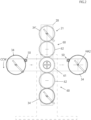
- the rotation device utilizing gravity of this embodiment includes
- the weight holding mechanisms 30 each includes
- L1 and L2 are configured so that L1 ⁇ L2 is satisfied.
- the support portion 31a of the weight body 32 in the weight support rotation body 31 is provided at a position where a reaction force F1 ( Figure 6 ) from the turning force receiving member 33 does not rotate the weight support rotation body 31 in the same direction CW as the rotation direction of the aforementioned main rotation body 20.
- the support portion 31a is desirably provided at a position where the reaction force F1 ( Figure 6 ) from the turning force receiving member 33 generates a rotation force T3 that tries to rotate the weight support rotation body 31 in an opposite direction CCW to the rotation direction of the main rotation body 20, and this is the case in this embodiment.
- the rotation device utilizing gravity of this embodiment further includes
- the power applying mechanism 50 has a configuration including a motor 50M, and a drive gear 51 fixed to an output shaft 52 of the motor 50M.
- the power applying mechanisms 50 are provided for the two weight holding mechanisms 30, but the power applying mechanism 50 may be provided for only one weight holding mechanism 30, or may be provided for each of all the weight holding mechanisms 30.
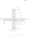
- the force receiving rotation body interlocking mechanisms 60 may be provided only for the force receiving rotation body 34' of the plurality of weight holding mechanisms 30 as shown in Figure 2 , except for the weight holding mechanism 30 in which the force receiving rotation body 34 is rotated by the power applying mechanisms 50 described above, or may be provided for the receiving rotators 34 of all weight holding mechanisms 30.
- the plurality of weight holding mechanisms 30 each provided at the installation position 21 on the main rotation body 20, separated by the rotation radius R from the rotation center O of the main rotation body 20 mounted rotatably around the horizontal axis (HA1) with respect to the base body 10, and equiangularly spaced from one another with respect to the rotation center O each includes the weight body 32, and the weight body 32 is turnably supported at the support portion 31a other than the rotation center (HA2) of the weight support rotation body 31 with respect to the weight support rotation body 31 provided rotatably around the horizontal axis (HA1) with respect to the main rotation body 20 in the weight holding mechanism 30, and tries to turn the weight body 32 itself in the same direction CW as the main rotation body 20 (see Figure 6 ).
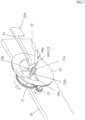
- the turning force (torque) T1 is transmitted to the turning force receiving member 33 provided to be rotatable concentrically with the rotation center (HA2) of the weight support rotation body 31, at the first turning force receiving position P1, and tries to turn the turning force receiving member 33 in the clockwise direction CW (see T2) .
- the turning force T2 (accordingly T1) is transmitted to the force receiving rotation body 34 provided to be rotatable concentrically with the rotation center (HA2) of the weight support rotation body 31 at the second turning force receiving position P2 to try to turn the force receiving rotation body 34 in the clockwise direction CW with the turning force T2.
- the main rotation body 20 rotates in the clockwise direction CW, in the state of the orientation in which the weight bodies 32 are maintained on the right side substantially in the horizontal direction in the installation positions 21 of the weight holding mechanisms 30 on the main rotation body 20, and the basic principle (principle that the rotation body D can be rotated by positioning the positions of the plurality of mass points m attached to the rotation body D so that the moment (torque) acting on the rotation body D is always positive) described in paragraphs 0011 to 0032 of Patent Literature 1 described above is realized.
- this device will continue to operate, and the main rotation body 20 will continue to rotate, but since there is an energy loss actually, the device does not continue to operate.
- the power applying mechanism 50 applies the power T4 that rotates the force receiving rotation body 34 at the same angular velocity as the main rotation body 20 in the opposite direction CCW to the rotation direction of the main rotation body 20 to the force receiving rotation body 34 in at least one weight holding mechanism 30 of the plurality of weight holding mechanisms 30, and therefore, the device can continue to operate by the power T4.
- the support portion 31a of the weight body 32 in the weight support rotation body 31 is provided at the position where the reaction force F1 from the turning force receiving member 33 does not tries to rotate the weight support rotation body 31 in the same direction as the rotation direction of the main rotation body 20 (position where the rotation force T3 to tries to rotate the weight support rotation body 31 in the opposite direction CCW is generated in this embodiment), the rotation of the weight support rotation body 31 in the opposite direction CCW to the rotation direction of the main rotation body 20 is not hindered by providing the weight body 32. Rather, the rotation force T3 assists in rotation of the weight support rotation body 31 in the opposite direction CCW to the rotation direction of the main rotation body 20 in this embodiment.
- the power T4 that rotates the force receiving rotation body 34 in the weight holding mechanism 30 at the same angular velocity as the main rotation body 20 in the opposite direction CCW to the rotation direction of the main rotation body 20 can be decreased.
- the power applying mechanism 50 can be provided for the at least one weight holding mechanism 30, and for the other weight holding mechanisms 30, the force receiving rotation bodies 34 can be interlocked with the rotation of the main rotation body 20 to be rotated at the same angular velocity as the main rotation body 20 in the opposite direction CCW to the rotation direction of the main rotation body 20 by the force receiving rotation body interlocking mechanisms 60, so that the power T4 by the above-described power applying mechanism 50 can be further decreased.
- the rotation device utilizing gravity of the present invention it is possible to rotate the rotation body by utilizing gravity by positioning the positions of the mass points (located between the support portions 31a and the weights 32w of the weight support rotation bodies 31 though not illustrated) of the plurality of weight bodies 32 attached to the rotation body so that the moment (torque) acting on the rotation body is always positive by small power.
- the four weight holding mechanisms 30 are provided, and the power by the power applying mechanism 50 is configured to be applied to at least a pair (left and right in Figure 1 ) of weight holding mechanisms 30 that are point-symmetrical with respect to the rotation center O of the main rotation body 20.
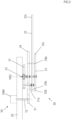
- the base body 10 has a bottom portion 11, and a front and rear support walls 12 and 12 raised from the bottom portion 11.
- the base body 10 is installed on the ground.
- the main rotation body 20 is a plate-shaped body in a cross shape in front view, and a shaft 22 ( Figure 4 ) fixed to a center portion thereof is rotatably supported at the support walls 12 and 12 of the base body with bearing members 13, as shown in Figure 1 and Figure 3 .
- the shaft 22 rotates with the main rotation body 20, and therefore can be used as an output shaft for extracting the power from this device.
- a front shape of the main rotation body 20 is not limited to the cross shape, and a disc shape, a radial shape or the like can be adopted.
- the weight support rotation body 31 is composed of a spur gear (hereinafter, also simply referred to as a gear) provided rotatably with respect to the main rotation body 20 by a shaft 23 ( Figure 5 ) provided at the main rotation body 20.
- a spur gear hereinafter, also simply referred to as a gear
- the weight support rotation body 31 is provided with a pin (31a) composing the support portion 31a, and the weight body 32 is provided to be swingable with respect to the weight support rotation body 31 by this pin (shaft) 31a.
- the weight body 32 is a lever-shaped member, and a weight 32w is provided at one end (in the illustrated case, a right end) 32c thereof.
- the other end (left end) 32b abuts on one end (upper end) 33b of the turning force receiving member 33 at the first turning force receiving position P1.
- the turning force receiving member 33 is a lever-shaped member provided turnably with respect to the main rotation body 20 by the shaft 23, the one end 33b abuts on the other end 32b of the weight body 32, and the other end 33c abuts on a pin 34p provided at the force receiving rotation body 34 in the aforementioned second turning force receiving position P2.
- the force receiving rotation body 34 is composed of a gear provided rotatably with respect to the main rotation body 20 by the shaft 23 (HA2) provided at the main rotation body 20.
- the force receiving rotation body 34 has a larger diameter than the weight support rotation body 31, and is provided with a space 34s for avoiding interference with the pin 31a provided at the weight support rotation body 31.
- the weight support rotation body 31, the force receiving rotation body 34, the weight body 32, and the turning force receiving member 33 are disposed in this order, seen from a back side (upper side in Figure 5 ), and since the pin (shaft) 31a that supports the weight body 32 penetrates through the force receiving rotation body 34, the force receiving rotation body 34 is provided with the space 34s for avoiding interference with the pin 31a.
- the respective members that compose the weight holding mechanism 30 do not move relatively among the respective members, but rotate around the rotation center O of the main rotation body 20 while maintaining a same orientation as the entire weight holding mechanism 30, and therefore, if the above-described space 34s is provided, the pin 31a and the force receiving rotation body 34 do not interfere with each other.
- the weight support rotation body interlocking mechanism 40 has the weight support rotation body (gear) 31, a center gear 41 fixed to the base body 10 to be unable to rotate, and intermediate gears 42, 43 and 44 provided between these gears 31 and 41.
- the intermediate gears 42, 43, and 44 are respectively provided rotatably with respect to the main rotation body 20.
- These gears 41 to 44 and 31 are all gears with a same pitch circle diameter, and a same number of teeth.
- the weight support rotation body (gear) 31 is interlocked with the rotation of the main rotation body 20 to rotate at the same angular velocity as the main rotation body 20 in the opposite direction CCW to the rotation direction of the main rotation body 20.
- the center gear 41 and the gear 31 composing the weight support rotation body are gears with the same pitch circle diameter, and the same number of teeth, it is possible to properly set pitch circler diameters of the intermediate gears 42, 43 and 44 and the numbers of teeth thereof (see Figure 13 , for example)).
- the weight support rotation body (gear) 31 rotates around the base body 10 (center gear 41) while maintaining the same orientation.
- reference sign 45 denotes a bolt that fixes the center gear 41 to the base body 10 with a center gear 61 described later.
- the drive applying mechanism 50 is configured by including the motor 50M, and the drive gear 51 fixed to the output shaft 52 of the motor 50M.
- the drive gear (pinion gear) 51 is fixed to the output shaft 52 of the motor 50M, the drive gear 51 is meshed with the force receiving rotation body (gear) 34, and rotates the force receiving rotation body 34 at the same angular velocity as the main rotation body 20 in the opposite direction CCW to the rotation direction of the main rotation body 20.
- the force receiving rotation body (gear) 34 rotates around the base body 10 while maintaining the same orientation.
- the force receiving rotation body interlocking mechanism 60 has a force receiving rotation body (gear) 34', the center gear 61 fixed to the base body 10 to be unable to rotate, and an intermediate gear 62 provided between these gears 61 and 34' .
- the intermediate gear 62 is provided rotatably with respect to the main rotation body 20.
- These gears 61, 62, and 34' are gears having a same pitch circle diameter and a same number of teeth. (Note that if the center gear 61 and the gear 34 composing the force receiving rotation body are the gears having the same pitch circle diameter and the same number of teeth, a pitch circle diameter and a number of teeth of the intermediate gear 62 can be properly set) .
- the force receiving rotation body (gear) 34' is interlocked with the rotation of the main rotation body 20 to rotate at a same angular velocity as the main rotation body 20 in the opposite direction CCW to the rotation direction of the main rotation body 20.
- the force receiving rotation body (gear) 34' rotates around the base body 10 (center gear 61) while maintaining the same orientation.
- the center gear 61 is fixed to the base body 10 together with the center gear 41 with the bolt 45 as mentioned above.
- weight support rotation body (gear) 31, and the force receiving rotation bodies (gears) 34 and 34' each rotates around the base body 10 (center gear 61) while maintaining the same orientation as described above, respective members composing the weight holding mechanism 30 including these members do not relatively move among the respective members, but rotate around the rotation center O of the main rotation body 20 while maintaining the same orientation, as the entire weight holding mechanism 30.
- the weight support rotation body interlocking mechanism 40 has the configuration having the weight support rotation body (gear) 31, the center gear 41 fixed to the base body 10 to be unable to rotate, and the intermediate gears 42, 43, and 44 provided between these gears 31 and 41, but may also have a configuration in which a timing pulley 42p is provided on the intermediate gear 42 which is meshed with the center gear 41 to be integrally rotatable, the weight support rotation body 31 is similarly composed of a timing pulley, and these pulleys are interlocked by a timing belt 46, as shown in Figure 9 , for example.
- a bevel gear 42b is provided on the intermediate gear 42 that is meshed with the center gear 41 to be integrally rotatable, the weight support rotation body 31 is also composed of a bevel gear, and these bevel gears can be configured to be interlocked with each other by an interlock rod 47 having bevel gears 47b at both ends.
- the weight support rotation body 31 can be composed of a sprocket, and can be interlocked with a sprocket provided in place of the center gear 41 with a chain.
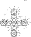
- the intermediate gear 62 is not provided between the center gear 61 and the force receiving rotation body 34, but may be provided therebetween (see Figure 11 ).
- the force receiving rotation body 34 in this embodiment is a double gear, in which a gear 34f on a front side is meshed with a drive gear 51 of the power applying mechanism 50, and a gear 34b on a rear side is meshed with the intermediate gear 62 composing the force receiving rotation body interlocking mechanism 60.
- a gear 34f on a front side is meshed with a drive gear 51 of the power applying mechanism 50
- a gear 34b on a rear side is meshed with the intermediate gear 62 composing the force receiving rotation body interlocking mechanism 60.
- the intermediate gears 62 composing the force receiving rotation body interlocking mechanisms 60 are provided for all the force receiving rotation bodies 34 between the center gear 61 and all the force receiving rotation bodies 34, and the power applying mechanisms 50 are provided for all the force receiving rotation bodies 34, for example, it becomes possible to decrease a power T4 by each of the power applying mechanisms 50.
- a support portion 31a of the weight body 32 in the weight support rotation body 31 is provided at a position where a reaction force F1 from the turning force receiving member 34 does not tries to rotate the weight support rotation body 31 in a same direction as the rotation direction of the main rotation body 20 (a rotation force T3 that tries to rotate the weight support rotation body 31 desirably in an opposite direction is generated), rotation of the weight support rotation body 31 in the opposite direction to the rotation direction of the main rotation body 20 is not hindered by providing the weight body 32.
- a turning force receiving member 33 is not used, it is possible to reduce the number of components and simplify the structure.
- the power applying mechanisms 50 are provided for all the force receiving rotation bodies 34, it becomes possible to decrease a power T4 by each of the power applying mechanisms 50 without necessarily providing the force receiving rotation body interlocking mechanisms 60.
- the power T4 by the power applyingmechanism 50 can be decreased, and since a support portion 31a of a weight body 32 in a weight support rotation body 31 is provided at a position where a reaction force F1 from the turning force receiving member 34 does not tries to rotate the weight support rotation body 31 in a same direction as the rotation direction of the main rotation body 20 (a rotation force T3 to tries to rotate the weight support rotation body 31 in an opposite direction is generated), rotation of the weight support rotation body 31 in the opposite direction to the rotation direction of the main rotation body 20 is not hindered by providing the weight body 32.
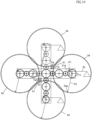
- a drive gear 51 of the power applying mechanism 50 drives the force receiving rotation body (gear) 34 via a double gear (speed reduction gear) 53 having a large gear 53L, and a small gear 53S.
- the drive gear 51 is meshed with the large gear 53L
- the small gear 53S is meshed with the force receiving rotation body (gear) 34.
- the one drive gear 51 is simultaneously meshed with a pair of speed reduction gears 53 adjacent to each other in a circumferential direction, and the one drive gear 51 (that is, the one power applying mechanism 50) simultaneously drives the two force receiving rotation bodies 34.
- the power applying mechanisms 50 are provided for all the force receiving rotation bodies 34, it becomes possible to decrease a power T4 by each of the power applying mechanisms 50 without necessarily providing the force receiving rotation body interlocking mechanisms 60.
- the power T4 by the power applyingmechanism 50 can be decreased, and since a support portion 31a of a weight body 32 in a weight support rotation body 31 is provided at a position where a reaction force F1 from the turning force receiving member 33 does not tries to rotate the weight support rotation body 31 in a same direction as the rotation direction of the main rotation body 20 (a rotation force T3 to tries to rotate the weight support rotation body 31 in an opposite direction is generated), rotation of the weight support rotation body 31 in the opposite direction to the rotation direction of the main rotation body 20 is not hindered by providing the weight body 32.
- the drive gear 51 of the power applying mechanism 50 directly drives the force receiving rotation body (gear) 34 composed of a large gear.
- the one drive gear 51 is simultaneously meshed with a pair of force receiving rotation bodies 34 adjacent to each other in a circumferential direction, and the one drive gear 51 (that is, the one power applying mechanism 50) simultaneously drives the two force receiving rotation bodies 34 (see Figure 15 ).
- the power applying mechanism 50 of this embodiment is configured by having a worm gear with a self-locking function.
- the drive applying mechanism 50 includes a motor 50M, and a worm gear box 54 having a worm 54c fixed to an output shaft 52 of the motor 50M, and a worm wheel 54d (see Figure 19 ) meshed with the worm 54c, and the drive gear 51 is fixed to an output shaft (shaft of the worm wheel 54d) 54b of the worm gear box 54.
- the worm gear has a self-locking function, and therefore can prevent reverse rotation of the force receiving rotation body 34, that is, reverse rotation of the main rotation body 20 when the rotation device utilizing gravity is stopped for some reason.
- a main difference of the rotation device utilizing gravity of the embodiment the main part of which is shown in Figure 16 from the embodiment shown in Figure 13 lies in a point that the rotation device utilizing gravity is configured without using the turning force receiving member 33, and there is no fundamental difference in other respects.
- the power applying mechanisms 50 are provided for all the force receiving rotation bodies 34, it becomes possible to decrease a power T4 by each of the power applying mechanisms 50 without necessarily providing the turning force receiving members 33 and the force receiving rotation body interlocking mechanisms 60.
- a support portion 31a of a weight body 32 in a weight support rotation body 31 is also provided at a position where a reaction force F1 from the turning force receiving member 33 does not tries to rotate the weight support rotation body 31 in a same direction as the rotation direction of the main rotation body 20 (a rotation force T3 to tries to rotate the weight support rotation body 31 in an opposite direction is generated) in this embodiment, rotation of the weight support rotation body 31 in the opposite direction to the rotation direction of the main rotation body 20 is not hindered by providing the weight body 32.
- a main difference of the rotation device utilizing gravity of the embodiment the main part of which is shown in Figure 17 and Figure 18 from the embodiment shown in Figure 14 and Figure 15 lies in a point that the rotation device utilizing gravity is configured without using the turning force receiving members 33, and there is no fundamental difference in other respects.
- a power T4 is decreased by increasing a diameter of each of the force receiving rotation bodies 34 and providing a pin 34p close to an outer peripheral portion of each of the force receiving rotation bodies, and by configuring a contact arm 32a with the pin 34p in a lever-shaped weight body 32 as long as possible.
- the power applying mechanism 50 in this embodiment is also configured by having a worm gear with a self-locking function, and therefore it is possible to rotate the force receiving rotation body 34 at a same angular velocity as a main rotation body 20 in an opposite direction to a rotation direction of the main rotation body 20 with the smaller power T4.
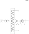
- FIG. 19 An embodiment a main part of which is shown in Figure 19 and Figure 20 shows a modification of the power applying mechanism 50 in the embodiment shown in Figure 1 and Figure 4 to Figure 6 .
- Amain difference of this embodiment from the embodiment shown in Figure 1 and Figure 4 to Figure 6 lies in a point that a power applying mechanism 50 is configured by having a worm gear with a self-locking function, and there is basically no basic change in the other points.
- the power applying mechanism 50 shown in Figure 19 and Figure 20 have a same basic structure as the drive applying mechanism shown in Figure 15 , and includes a motor 50M, and a worm gear box 54 having a worm 54c fixed to an output shaft 52 of the motor 50M and a worm wheel 54d that is meshed with the worm 54c, and a drive gear 51 is fixed to an output shaft (shaft of the worm wheel 54d) 54b of the worm gear box 54.
- the power applying mechanism 50 like this is also applicable to an embodiment without having turning force receiving members 33, for example, an embodiment shown in Figure 23 .
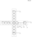
- FIG. 21 and Figure 22 shows a modification of the power applying mechanism 50 in the embodiment shown in Figure 1 and Figure 4 to Figure 6 .
- Amain difference of this embodiment from the embodiment shown in Figure 1 and Figure 4 to Figure 6 lies in a point that a power applying mechanism 50 is configured by having a worm gear with a self-locking function, and there is no fundamental difference in other respects.
- the power applying mechanism 50 shown in Figure 21 and Figure 22 includes a motor 50M having output shafts 52 on a top and a bottom, drive gears 55 fixed respectively to a top and a bottom of the output shafts 52, and a worm 57 driven by the drive gears 55 via transmission gears 56 respectively fixed to a top and a bottom of a shaft of the worm 57, and a force receiving rotation body 34 configured as a worm wheel is rotated at a same angular velocity as a main rotation body 20 in an opposite direction to a rotation direction of the main rotation body 20 by this worm 57.
- the power applying mechanism 50 like this is also applicable to an embodiment without having the turning force receiving member 33 and the force receiving rotation body interlocking mechanism 60, for example, an embodiment as shown in Figure 24 .
- the rotation device utilizing gravity of this invention can utilize the rotation of the main rotation body 20 as power.
Landscapes
- Engineering & Computer Science (AREA)
- Chemical & Material Sciences (AREA)
- Combustion & Propulsion (AREA)
- Mechanical Engineering (AREA)
- General Engineering & Computer Science (AREA)
- Adjustment Of Camera Lenses (AREA)
- Other Liquid Machine Or Engine Such As Wave Power Use (AREA)
- Motorcycle And Bicycle Frame (AREA)
- Connection Of Motors, Electrical Generators, Mechanical Devices, And The Like (AREA)
Applications Claiming Priority (2)
| Application Number | Priority Date | Filing Date | Title |
|---|---|---|---|
| JP2021149211A JP7047177B1 (ja) | 2021-09-14 | 2021-09-14 | 重力利用回転装置 |
| PCT/JP2022/033997 WO2023042778A1 (ja) | 2021-09-14 | 2022-09-12 | 重力利用回転装置 |
Publications (2)
| Publication Number | Publication Date |
|---|---|
| EP4403799A1 true EP4403799A1 (de) | 2024-07-24 |
| EP4403799A4 EP4403799A4 (de) | 2026-01-07 |
Family
ID=81256633
Family Applications (1)
| Application Number | Title | Priority Date | Filing Date |
|---|---|---|---|
| EP22869925.2A Pending EP4403799A4 (de) | 2021-09-14 | 2022-09-12 | Schwerkraft verwendende drehvorrichtung |
Country Status (3)
| Country | Link |
|---|---|
| EP (1) | EP4403799A4 (de) |
| JP (1) | JP7047177B1 (de) |
| WO (1) | WO2023042778A1 (de) |
Family Cites Families (9)
| Publication number | Priority date | Publication date | Assignee | Title |
|---|---|---|---|---|
| JPS5440948A (en) | 1977-09-06 | 1979-03-31 | Fumio Nakayama | Method of obtaining power by descending pressure of heavy weight attached to driving wheel |
| JPH0458068A (ja) * | 1990-06-27 | 1992-02-25 | Takashi Nosaka | 重力回転機関とその発電装置 |
| CN102808746A (zh) * | 2011-05-31 | 2012-12-05 | 邱金和 | 动力产生装置 |
| JP5517376B1 (ja) * | 2013-03-27 | 2014-06-11 | 岩間 敏子 | 回転促進装置 |
| JP5759520B2 (ja) * | 2013-08-12 | 2015-08-05 | 株式会社シンプル東京 | 回転装置 |
| JP2017016824A (ja) | 2015-06-30 | 2017-01-19 | 株式会社村田製作所 | バイメタル素子 |
| JP6069776B1 (ja) * | 2016-03-10 | 2017-02-01 | 元 井嶋 | 回転出力倍化装置 |
| JP2020056311A (ja) | 2017-02-01 | 2020-04-09 | 日吉 藤本 | 動力発生装置 |
| US20200049132A1 (en) * | 2018-08-12 | 2020-02-13 | Jerry Gene Warthan | Offset Weight-Powered Engine |
-
2021
- 2021-09-14 JP JP2021149211A patent/JP7047177B1/ja active Active
-
2022
- 2022-09-12 EP EP22869925.2A patent/EP4403799A4/de active Pending
- 2022-09-12 WO PCT/JP2022/033997 patent/WO2023042778A1/ja not_active Ceased
Also Published As
| Publication number | Publication date |
|---|---|
| WO2023042778A1 (ja) | 2023-03-23 |
| JP2023042103A (ja) | 2023-03-27 |
| JP7047177B1 (ja) | 2022-04-04 |
| EP4403799A4 (de) | 2026-01-07 |
Similar Documents
| Publication | Publication Date | Title |
|---|---|---|
| JP5088970B2 (ja) | 偏心型減速機 | |
| CN101772657B (zh) | 齿轮装置及使用齿轮装置的工业机器人的转动部结构 | |
| JP5072964B2 (ja) | 風力発電装置 | |
| CN102109029B (zh) | 减速机构 | |
| CN101827955B (zh) | 工件承载器装置 | |
| KR101275249B1 (ko) | 하이브리드 감속기 | |
| US20160091053A1 (en) | Epicyclic gear train | |
| US20100296933A1 (en) | Transmission system for power generation | |
| WO2011027427A1 (ja) | 風力発電装置 | |
| EP4403799A1 (de) | Schwerkraft verwendende drehvorrichtung | |
| JP5069650B2 (ja) | 偏心型減速機 | |
| US7165474B2 (en) | Torque dividing gear drive system and method of driving an output gear | |
| JP2009250213A (ja) | 風力発電装置 | |
| US8337355B2 (en) | Eccentric speed reducer | |
| KR20100016356A (ko) | 회전 구동력 전달 장치 | |
| US12529413B2 (en) | Actuators | |
| KR100339845B1 (ko) | 감속기 | |
| EA053145B1 (ru) | Устройство вращения, использующее силу тяжести | |
| JPH0520616B2 (de) | ||
| JP2010196860A (ja) | 減速装置 | |
| JP2009228844A (ja) | 偏心差動減速機 | |
| JP4851826B2 (ja) | 内接揺動噛合型遊星歯車減速機 | |
| TWI671980B (zh) | 驅動裝置 | |
| JP2025043500A (ja) | 重力利用回転装置 | |
| JPH017882Y2 (de) |
Legal Events
| Date | Code | Title | Description |
|---|---|---|---|
| STAA | Information on the status of an ep patent application or granted ep patent |
Free format text: STATUS: THE INTERNATIONAL PUBLICATION HAS BEEN MADE |
|
| PUAI | Public reference made under article 153(3) epc to a published international application that has entered the european phase |
Free format text: ORIGINAL CODE: 0009012 |
|
| STAA | Information on the status of an ep patent application or granted ep patent |
Free format text: STATUS: REQUEST FOR EXAMINATION WAS MADE |
|
| 17P | Request for examination filed |
Effective date: 20240202 |
|
| AK | Designated contracting states |
Kind code of ref document: A1 Designated state(s): AL AT BE BG CH CY CZ DE DK EE ES FI FR GB GR HR HU IE IS IT LI LT LU LV MC MK MT NL NO PL PT RO RS SE SI SK SM TR |
|
| DAX | Request for extension of the european patent (deleted) | ||
| RAV | Requested validation state of the european patent: fee paid |
Extension state: KH Effective date: 20240202 |
|
| A4 | Supplementary search report drawn up and despatched |
Effective date: 20251210 |
|
| RIC1 | Information provided on ipc code assigned before grant |
Ipc: F16H 35/00 20060101AFI20251204BHEP Ipc: F03G 3/00 20060101ALI20251204BHEP |