EP4403796A1 - Getriebesystem für ein fahrzeug und elektrofahrzeug mit einem getriebesystem - Google Patents
Getriebesystem für ein fahrzeug und elektrofahrzeug mit einem getriebesystem Download PDFInfo
- Publication number
- EP4403796A1 EP4403796A1 EP23152621.1A EP23152621A EP4403796A1 EP 4403796 A1 EP4403796 A1 EP 4403796A1 EP 23152621 A EP23152621 A EP 23152621A EP 4403796 A1 EP4403796 A1 EP 4403796A1
- Authority
- EP
- European Patent Office
- Prior art keywords
- gear assembly
- sprocket
- output
- shaft
- transmission system
- Prior art date
- Legal status (The legal status is an assumption and is not a legal conclusion. Google has not performed a legal analysis and makes no representation as to the accuracy of the status listed.)
- Granted
Links
Images


Classifications
-
- F—MECHANICAL ENGINEERING; LIGHTING; HEATING; WEAPONS; BLASTING
- F16—ENGINEERING ELEMENTS AND UNITS; GENERAL MEASURES FOR PRODUCING AND MAINTAINING EFFECTIVE FUNCTIONING OF MACHINES OR INSTALLATIONS; THERMAL INSULATION IN GENERAL
- F16H—GEARING
- F16H37/00—Combinations of mechanical gearings, not provided for in groups F16H1/00 - F16H35/00
- F16H37/12—Gearings comprising primarily toothed or friction gearing, links or levers, and cams, or members of at least two of these types
-
- B—PERFORMING OPERATIONS; TRANSPORTING
- B60—VEHICLES IN GENERAL
- B60W—CONJOINT CONTROL OF VEHICLE SUB-UNITS OF DIFFERENT TYPE OR DIFFERENT FUNCTION; CONTROL SYSTEMS SPECIALLY ADAPTED FOR HYBRID VEHICLES; ROAD VEHICLE DRIVE CONTROL SYSTEMS FOR PURPOSES NOT RELATED TO THE CONTROL OF A PARTICULAR SUB-UNIT
- B60W10/00—Conjoint control of vehicle sub-units of different type or different function
- B60W10/04—Conjoint control of vehicle sub-units of different type or different function including control of propulsion units
- B60W10/08—Conjoint control of vehicle sub-units of different type or different function including control of propulsion units including control of electric propulsion units, e.g. motors or generators
-
- F—MECHANICAL ENGINEERING; LIGHTING; HEATING; WEAPONS; BLASTING
- F16—ENGINEERING ELEMENTS AND UNITS; GENERAL MEASURES FOR PRODUCING AND MAINTAINING EFFECTIVE FUNCTIONING OF MACHINES OR INSTALLATIONS; THERMAL INSULATION IN GENERAL
- F16H—GEARING
- F16H3/00—Toothed gearings for conveying rotary motion with variable gear ratio or for reversing rotary motion
- F16H3/02—Toothed gearings for conveying rotary motion with variable gear ratio or for reversing rotary motion without gears having orbital motion
- F16H3/08—Toothed gearings for conveying rotary motion with variable gear ratio or for reversing rotary motion without gears having orbital motion exclusively or essentially with continuously meshing gears, that can be disengaged from their shafts
- F16H3/10—Toothed gearings for conveying rotary motion with variable gear ratio or for reversing rotary motion without gears having orbital motion exclusively or essentially with continuously meshing gears, that can be disengaged from their shafts with one or more one-way clutches as an essential feature
-
- B—PERFORMING OPERATIONS; TRANSPORTING
- B60—VEHICLES IN GENERAL
- B60K—ARRANGEMENT OR MOUNTING OF PROPULSION UNITS OR OF TRANSMISSIONS IN VEHICLES; ARRANGEMENT OR MOUNTING OF PLURAL DIVERSE PRIME-MOVERS IN VEHICLES; AUXILIARY DRIVES FOR VEHICLES; INSTRUMENTATION OR DASHBOARDS FOR VEHICLES; ARRANGEMENTS IN CONNECTION WITH COOLING, AIR INTAKE, GAS EXHAUST OR FUEL SUPPLY OF PROPULSION UNITS IN VEHICLES
- B60K6/00—Arrangement or mounting of plural diverse prime-movers for mutual or common propulsion, e.g. hybrid propulsion systems comprising electric motors and internal combustion engines
- B60K6/20—Arrangement or mounting of plural diverse prime-movers for mutual or common propulsion, e.g. hybrid propulsion systems comprising electric motors and internal combustion engines the prime-movers consisting of electric motors and internal combustion engines, e.g. HEVs
- B60K6/22—Arrangement or mounting of plural diverse prime-movers for mutual or common propulsion, e.g. hybrid propulsion systems comprising electric motors and internal combustion engines the prime-movers consisting of electric motors and internal combustion engines, e.g. HEVs characterised by apparatus, components or means specially adapted for HEVs
- B60K6/36—Arrangement or mounting of plural diverse prime-movers for mutual or common propulsion, e.g. hybrid propulsion systems comprising electric motors and internal combustion engines the prime-movers consisting of electric motors and internal combustion engines, e.g. HEVs characterised by apparatus, components or means specially adapted for HEVs characterised by the transmission gearings
-
- B—PERFORMING OPERATIONS; TRANSPORTING
- B60—VEHICLES IN GENERAL
- B60W—CONJOINT CONTROL OF VEHICLE SUB-UNITS OF DIFFERENT TYPE OR DIFFERENT FUNCTION; CONTROL SYSTEMS SPECIALLY ADAPTED FOR HYBRID VEHICLES; ROAD VEHICLE DRIVE CONTROL SYSTEMS FOR PURPOSES NOT RELATED TO THE CONTROL OF A PARTICULAR SUB-UNIT
- B60W10/00—Conjoint control of vehicle sub-units of different type or different function
- B60W10/02—Conjoint control of vehicle sub-units of different type or different function including control of driveline clutches
- B60W10/024—Conjoint control of vehicle sub-units of different type or different function including control of driveline clutches including control of torque converters
-
- F—MECHANICAL ENGINEERING; LIGHTING; HEATING; WEAPONS; BLASTING
- F16—ENGINEERING ELEMENTS AND UNITS; GENERAL MEASURES FOR PRODUCING AND MAINTAINING EFFECTIVE FUNCTIONING OF MACHINES OR INSTALLATIONS; THERMAL INSULATION IN GENERAL
- F16H—GEARING
- F16H37/00—Combinations of mechanical gearings, not provided for in groups F16H1/00 - F16H35/00
- F16H37/02—Combinations of mechanical gearings, not provided for in groups F16H1/00 - F16H35/00 comprising essentially only toothed or friction gearings
-
- F—MECHANICAL ENGINEERING; LIGHTING; HEATING; WEAPONS; BLASTING
- F16—ENGINEERING ELEMENTS AND UNITS; GENERAL MEASURES FOR PRODUCING AND MAINTAINING EFFECTIVE FUNCTIONING OF MACHINES OR INSTALLATIONS; THERMAL INSULATION IN GENERAL
- F16H—GEARING
- F16H57/00—General details of gearing
- F16H57/02—Gearboxes; Mounting gearing therein
- F16H57/023—Mounting or installation of gears or shafts in the gearboxes, e.g. methods or means for assembly
-
- F—MECHANICAL ENGINEERING; LIGHTING; HEATING; WEAPONS; BLASTING
- F16—ENGINEERING ELEMENTS AND UNITS; GENERAL MEASURES FOR PRODUCING AND MAINTAINING EFFECTIVE FUNCTIONING OF MACHINES OR INSTALLATIONS; THERMAL INSULATION IN GENERAL
- F16H—GEARING
- F16H7/00—Gearings for conveying rotary motion by endless flexible members
- F16H7/02—Gearings for conveying rotary motion by endless flexible members with belts; with V-belts
- F16H7/023—Gearings for conveying rotary motion by endless flexible members with belts; with V-belts with belts having a toothed contact surface or regularly spaced bosses or hollows for slipless or nearly slipless meshing with complementary profiled contact surface of a pulley
-
- F—MECHANICAL ENGINEERING; LIGHTING; HEATING; WEAPONS; BLASTING
- F16—ENGINEERING ELEMENTS AND UNITS; GENERAL MEASURES FOR PRODUCING AND MAINTAINING EFFECTIVE FUNCTIONING OF MACHINES OR INSTALLATIONS; THERMAL INSULATION IN GENERAL
- F16H—GEARING
- F16H7/00—Gearings for conveying rotary motion by endless flexible members
- F16H7/06—Gearings for conveying rotary motion by endless flexible members with chains
-
- B—PERFORMING OPERATIONS; TRANSPORTING
- B60—VEHICLES IN GENERAL
- B60K—ARRANGEMENT OR MOUNTING OF PROPULSION UNITS OR OF TRANSMISSIONS IN VEHICLES; ARRANGEMENT OR MOUNTING OF PLURAL DIVERSE PRIME-MOVERS IN VEHICLES; AUXILIARY DRIVES FOR VEHICLES; INSTRUMENTATION OR DASHBOARDS FOR VEHICLES; ARRANGEMENTS IN CONNECTION WITH COOLING, AIR INTAKE, GAS EXHAUST OR FUEL SUPPLY OF PROPULSION UNITS IN VEHICLES
- B60K1/00—Arrangement or mounting of electrical propulsion units
- B60K2001/001—Arrangement or mounting of electrical propulsion units one motor mounted on a propulsion axle for rotating right and left wheels of this axle
-
- B—PERFORMING OPERATIONS; TRANSPORTING
- B60—VEHICLES IN GENERAL
- B60W—CONJOINT CONTROL OF VEHICLE SUB-UNITS OF DIFFERENT TYPE OR DIFFERENT FUNCTION; CONTROL SYSTEMS SPECIALLY ADAPTED FOR HYBRID VEHICLES; ROAD VEHICLE DRIVE CONTROL SYSTEMS FOR PURPOSES NOT RELATED TO THE CONTROL OF A PARTICULAR SUB-UNIT
- B60W2710/00—Output or target parameters relating to a particular sub-units
- B60W2710/08—Electric propulsion units
- B60W2710/083—Torque
-
- B—PERFORMING OPERATIONS; TRANSPORTING
- B60—VEHICLES IN GENERAL
- B60Y—INDEXING SCHEME RELATING TO ASPECTS CROSS-CUTTING VEHICLE TECHNOLOGY
- B60Y2200/00—Type of vehicle
- B60Y2200/90—Vehicles comprising electric prime movers
- B60Y2200/91—Electric vehicles
-
- F—MECHANICAL ENGINEERING; LIGHTING; HEATING; WEAPONS; BLASTING
- F16—ENGINEERING ELEMENTS AND UNITS; GENERAL MEASURES FOR PRODUCING AND MAINTAINING EFFECTIVE FUNCTIONING OF MACHINES OR INSTALLATIONS; THERMAL INSULATION IN GENERAL
- F16H—GEARING
- F16H2200/00—Transmissions for multiple ratios
- F16H2200/0021—Transmissions for multiple ratios specially adapted for electric vehicles
-
- F—MECHANICAL ENGINEERING; LIGHTING; HEATING; WEAPONS; BLASTING
- F16—ENGINEERING ELEMENTS AND UNITS; GENERAL MEASURES FOR PRODUCING AND MAINTAINING EFFECTIVE FUNCTIONING OF MACHINES OR INSTALLATIONS; THERMAL INSULATION IN GENERAL
- F16H—GEARING
- F16H2200/00—Transmissions for multiple ratios
- F16H2200/003—Transmissions for multiple ratios characterised by the number of forward speeds
- F16H2200/0034—Transmissions for multiple ratios characterised by the number of forward speeds the gear ratios comprising two forward speeds
-
- F—MECHANICAL ENGINEERING; LIGHTING; HEATING; WEAPONS; BLASTING
- F16—ENGINEERING ELEMENTS AND UNITS; GENERAL MEASURES FOR PRODUCING AND MAINTAINING EFFECTIVE FUNCTIONING OF MACHINES OR INSTALLATIONS; THERMAL INSULATION IN GENERAL
- F16H—GEARING
- F16H3/00—Toothed gearings for conveying rotary motion with variable gear ratio or for reversing rotary motion
- F16H3/02—Toothed gearings for conveying rotary motion with variable gear ratio or for reversing rotary motion without gears having orbital motion
- F16H3/08—Toothed gearings for conveying rotary motion with variable gear ratio or for reversing rotary motion without gears having orbital motion exclusively or essentially with continuously meshing gears, that can be disengaged from their shafts
- F16H3/087—Toothed gearings for conveying rotary motion with variable gear ratio or for reversing rotary motion without gears having orbital motion exclusively or essentially with continuously meshing gears, that can be disengaged from their shafts characterised by the disposition of the gears
- F16H3/093—Toothed gearings for conveying rotary motion with variable gear ratio or for reversing rotary motion without gears having orbital motion exclusively or essentially with continuously meshing gears, that can be disengaged from their shafts characterised by the disposition of the gears with two or more countershafts
-
- F—MECHANICAL ENGINEERING; LIGHTING; HEATING; WEAPONS; BLASTING
- F16—ENGINEERING ELEMENTS AND UNITS; GENERAL MEASURES FOR PRODUCING AND MAINTAINING EFFECTIVE FUNCTIONING OF MACHINES OR INSTALLATIONS; THERMAL INSULATION IN GENERAL
- F16H—GEARING
- F16H57/00—General details of gearing
- F16H57/0018—Shaft assemblies for gearings
- F16H57/0037—Special features of coaxial shafts, e.g. relative support thereof
Definitions
- the present disclosure relates to a transmission system for a vehicle and an electric vehicle comprising a transmission system.
- a design option in a transmission system is providing a multiple-speed gearbox, which allows usage of smaller electric machines/motors, as well as optimization of efficiencies. It is further advantageous to provide a transmission system that is as compact as an equivalent single speed transmission system with multiple gear stages. Such improvements may also provide reduction of mechanical losses in the drive systems of the vehicle.
- a transmission system for a vehicle comprising a first gear assembly, a second gear assembly, an intermediate unit and an output gear assembly with an output shaft.
- the intermediate unit comprises a first sprocket element, a second sprocket element and a coupling element.
- the first sprocket element is connectable to an input shaft of a traction motor of the vehicle in an axial direction of the first sprocket element to receive an input torque.
- the second sprocket element is arranged radially to the first sprocket element and in communication with the first sprocket element through the coupling element to receive the input torque.
- the first gear assembly is connectable to the second sprocket element coaxially to convert the input torque to a first output torque.
- the second gear assembly is connectable to the first sprocket element coaxially to convert the input torque to a second output torque.
- the output gear assembly is configured to selectively transfer the first output torque from the first gear assembly to the output shaft or the second output torque from the second gear assembly to the output shaft.
- a transmission system may act as a medium for transmitting a power generated by an engine/electric motor to at least a wheel of a vehicle via a mechanical system of gears or gear trains constituting a gear assembly.
- the transmission system may be a gear box.
- the transmission system may contribute to efficient driving of a vehicle by enabling controlling of the output torque delivered to the wheels based on the drive needs such as required torque/speed.
- transmission systems may comprise gears with different gear ratios. By allowing switching between the different gears the output torque provided to the wheels of the vehicle can be changed to fit the drive needs.
- the transmission system according to the present disclosure provides a compact design by arranging the first gear assembly in connection with the second gear assembly via the coupling element of the intermediate unit. Further, the arrangement of the first gear assembly and the second gear assembly being selectively connectable with the output gear assembly simplifies a change between the first output torque and the second output torque without requiring further transfer elements, such as more gears or gear couples. Accordingly, the torque transfer pathway between the input shaft and the output gear assembly is reduced to a minimum number of components. Thereby, the present transmission system improves an efficiency in transferring torque and reducing mechanical losses.
- the transmission system provides the above-mentioned advantages by the special arrangement of the intermediate unit as a central element of the transmission system.
- the intermediate unit comprising the coupling element that is in connection with the first sprocket element and the second sprocket element, enables the input torque to be transferred through the first gear assembly or the second gear assembly to the output gear assembly.
- the input torque of the traction motor of the vehicle may be received by the first sprocket element.
- the received torque may be transferred through the second gear assembly to obtain the second output torque.
- the input torque can be transferred through the coupling element to the second sprocket element, which may be connected to the first gear assembly, and can be obtained as the first output torque.
- the intermediate unit may provide a connection between the first and the second gear assembly to easily switch between the alternative torque pathways.
- the first sprocket element also called driving sprocket, may receive the input torque from the input shaft of the traction motor.
- the first sprocket element and the input shaft are connectable in an axial direction. For instance, they may share a central axis or their axes may be shifted but extending in parallel to each other.
- the first and the second sprocket elements may have a form of a simple sprocket-wheel as widely known in the technical field of gears, such as a profiled wheel with teeth that mesh with a chain, belt, track or other perforated or indented material.
- the traction motor may be powered by electricity to generate power for the wheels of the vehicle.
- the input shaft may extend out of the traction motor and convey input torque to the wheels via the transmission system and other components such as a drive shaft/driving shaft and differential.
- the input torque may be transferred to the second sprocket element, called driven sprocket, arranged radially to the first sprocket element through the coupling element of the intermediate member.
- Radial may mean that the first and the second sprocket elements may be arranged side by side on a plane passing through their centers.
- the first sprocket element and the second sprocket element may be spaced apart from each other that their connection may be provided only by the coupling element of the intermediate unit. This may be defined by the terms "in communication", which may indicate that the second sprocket element may be moved by the first sprocket element only through the coupling element, as the first and the second sprocket elements may not directly contact each other.
- the second gear assembly may be selected.
- the second gear assembly may be connected to the first sprocket element coaxially to convert the input torque to the second output torque.
- the first sprocket element may be aligned with the second gear assembly at a common central axis passing through a centre points of each.
- the input torque may be directly transferred from the first sprocket element to the second gear assembly and from there to the output gear assembly, without being transferred to the second sprocket element through the intermediate unit.
- the second sprocket element may still be in contact with the first sprocket element and the rotational motion of the first sprocket element may still be transferred to the second sprocket element.
- the output gear assembly may selectively transfer only the second output torque from the second gear assembly. Accordingly, in this case, the first output torque may not be transferred to the output gear assembly.
- the first output torque can be transferred from the first gear assembly to the output shaft or the second output torque can be transferred from the second gear assembly to the output shaft, selectively.
- the first gear assembly may be adapted to engage with the output gear assembly, while the second gear assembly may be disengaged from the output gear assembly, which may allow transmitting of the input torque to the output torque as the first output torque.
- the second gear assembly may be adapted to engage with the output gear assembly, while the first gear assembly may be disengaged from the output gear assembly, which may allow transmitting of the input torque to the output torque as the second output torque.
- the transmission system may provide different torque outputs depending on the selected torque transfer pathway.
- the first gear assembly comprises a first pinion element engageable with the output gear assembly in a circumferential direction of the output gear assembly
- the second gear assembly comprises a second pinion element engageable with the output gear assembly in a circumferential direction of the output gear assembly.
- the first and the second pinion elements and the output gear assembly may engage with each other from their peripheries.
- the first pinion element may be arranged coaxially with the second sprocket element, and between the second sprocket element and the output gear assembly to transfer a rotational motion of the second sprocket element to the output gear assembly.
- the second pinion element may be arranged axially with the first sprocket element, and between the first sprocket element and the output gear assembly to transfer a rotational motion of the first sprocket element to the output gear assembly. Accordingly, the first pinion element may be connectable to the second sprocket element and the second pinion element may be connectable to the first sprocket element.
- the engagement of the first and the second pinion elements to the output gear assembly may allow a selective transfer of the input torque coming from the first or the second sprocket elements.
- the rotational motion of the pinion elements and the output gear assembly may be in opposite directions.
- the rotational motion of the first pinion element and the second pinion element may be in the same direction. Accordingly, the input torque may be transferred from the first sprocket element to the second pinion element or from the second sprocket element to the first pinion element, and therefrom to the output gear assembly.
- the first gear assembly comprises a first clutch member coaxially positioned at the second sprocket element from one side and attachable to the first pinion element from another side.
- the first clutch member is configured to cause a delivery of the first output torque when being activated.
- Activation of the first clutch member may mean, to move the first clutch member in a direction towards the first pinion element to engage thereto.
- the first clutch member may engage to the first pinion element to transfer a rotational movement of the second sprocket element to the first pinion element.
- the rotational movement of the second sprocket element may originate from the motor/engine of the vehicle and may be transferred by the input shaft, the first sprocket element and the coupling element to the first pinion element.
- the first clutch member may be for instance a one-way clutch.
- the first clutch member may be any other kind of clutch, such as a friction clutch.
- a one-way clutch may move linearly only in one way.
- one-way clutch may extend only in one way.
- the first clutch member may be positioned at the second sprocket element and can only linearly move in a direction away from the second sprocket element.
- the first clutch member may be fixed to the second sprocket element from one side, while allowing the linear movement away from the second sprocket element from another side. Fixing of the first clutch member to the second sprocket element from one side may be via a fastening element such as a bolt or a screw.
- the first clutch member may be splined to the second sprocket element and fixed by a locking element such as a snap ring.
- the second sprocket element may be alternatively integrally formed with the first clutch member.
- the second sprocket element and the first clutch member may be monolithic.
- any other method for fixing the first clutch member to the second sprocket element may be preferred.
- the first clutch member may comprise a strut element arranged to prevent disengaging of the first gear assembly and/or the second gear assembly from the output gear assembly. This may be especially preferred when the vehicle is costing down.
- the second gear assembly comprises a second clutch member at a side of the second pinion element opposite to the first sprocket element and the second clutch member is configured to cause a delivery of the second output torque when being activated.
- Activation of the second clutch member may mean to cause a transfer of a rotational movement of the first sprocket element to the second pinion element.
- the second clutch member may be for instance a friction clutch.
- the second clutch member may be in an example a dry clutch, comprising multiple friction elements.
- the second clutch member may be exposed to reduced viscous drag torque between the friction elements.
- the viscous drag torque may be nearly around zero.
- the second clutch member, the second pinion element and the first sprocket element may have a common central axis passing through the centers of each second clutch member, second pinion element and first sprocket element.
- the second sprocket element comprises a recess facing the first pinion element, for receiving the first clutch member therein.
- the recess may be on a side of the second sprocket element in a direction of the first pinion element.
- the recess may be constructed to a size suitable for the first clutch member to be placed therein.
- the first clutch member may have a shape of a disc and the recess may have a circular shape and a thickness extending into the second sprocket element for enclosing the disc shaped first clutch member at least partially. Nevertheless, the first clutch member may have any other shape and the recess may be designed accordingly to at least partially enclose the first clutch member.
- the recess may comprise a through hole concentric with the second sprocket element. This construction of the second sprocket element and the first clutch member may provide an axially compact arrangement and further reduce the occupied space.
- the coupling element is a chain or a belt circumscribing the first sprocket element and the second sprocket element.
- the coupling element may allow a transfer of rotational movement from the first sprocket element to the second sprocket element.
- a sprocket and chain or belt combination may provide the transfer without any slippage or with reduced slippage during rotation.
- Using a coupling element of such sort may allow the first and the second sprocket elements to rotate in the same direction. Obtaining the same rotational direction from the first and the second sprocket element may simplify the transmission construction by reducing a number of required transfer members, such as further gear assemblies. Accordingly, the coupling element may have a higher efficiency and may contribute to the reduction of mechanical losses.
- the first sprocket element and the second sprocket element have different diameters. Accordingly, the first and the second output torque may be different to each other.
- the first sprocket element may be smaller in size than the second sprocket element.
- the second sprocket element may be smaller in size than the second sprocket element.
- the motor or electric machine capacity may be used optimally without overloading thereof.
- the second clutch member comprises a carrier element and an elastic element.
- the elastic element is arranged on the carrier element at a side opposite to the second pinion element.
- the carrier element may securely hold the elastic element in place.
- the carrier element may additionally provide an enclosure for the friction elements to be stored therein.
- the elastic element may be a diaphragm spring.
- the diaphragm spring may be prestressed and apply a positive force to the carrier element when activated. When the diaphragm spring is inactivated, the spring may be released and return to its original shape.
- Arranging the elastic element at a side opposite to the second pinion element may counterweight a force (load) accumulated on the side of the carrier element. Accordingly, high stiffness on this side may be balanced.
- the first gear assembly comprises a first coupling shaft extending coaxially to the second sprocket element.
- a central axis of the recess of the second sprocket element may be coaxial with a central axis of the first coupling shaft.
- the first coupling shaft may be a lay shaft of the transmission system.
- the first coupling shaft may be a shaft which is configured to accommodate the second sprocket element and the first gear assembly and provide a central axis thereto.
- the first coupling shaft may not directly connect to the output shaft to provide the output torque. It may rather be understood as an intermediary component of the transmission system.
- the first coupling shaft may rotatably extend through the central axis of the second sprocket element.
- the through hole of the recess of the second sprocket element may be aligned with the first coupling shaft for it to extend therethrough.
- the first gear assembly comprises a first convey shaft concentric to the first coupling shaft.
- the first pinion element is mounted on the first convey shaft.
- the first clutch member is configured to cause the first convey shaft to engage with the first coupling shaft, thereby converting the input torque to the first output torque, when activated. Accordingly, the first clutch member may be configured to secure the first convey shaft to the first coupling shaft when activated, for the first convey shaft and the first coupling shaft to rotate together.
- the second gear assembly comprises a second coupling shaft extending coaxially to the first sprocket element.
- the first sprocket element may comprise a concentrically extending second through hole for the input shaft to rotatably extend therethrough.
- the second coupling shaft may concentrically extend from the second clutch member towards the first sprocket element.
- the input shaft is arranged concentrically inside the second coupling shaft.
- the input shaft may be freely rotatable inside the second coupling shaft when the second clutch member is not activated.
- the second clutch may cause the input shaft to engage with the second coupling shaft when activated, therefore not allowing the input shaft to freely rotate inside the second coupling shaft.
- the second pinion element is mounted on the second coupling shaft.
- the second clutch member is configured to cause the input shaft to engage with the second coupling shaft, thereby converting the input torque to the second output torque, when activated.
- first pinion element and/or the second pinion element may be engaged to the output gear assembly permanently.
- first pinion element and/or the second pinion element may be attached to the output gear assembly without needing to be separated therefrom.
- the first clutch member and/or the second clutch member may be configured to cause a delivery of the first or the second output torque, respectively, independent of if the first or the second pinion elements are engaged to the output gear assembly.
- the second clutch member when the second clutch member disengages from the second pinion element by deactivation, the output speed of the first clutch member may fall below the input torque. Accordingly the first clutch member may become automatically activated. In principle, when the output speed is higher than the input speed, no output torque may be transmitted through the respective clutch member. On the other hand, if the input speed is higher than the output speed, the clutch member may stay connected with the input, for instance being in connection with the input shaft. This can be considered as if the first clutch member overruns the second clutch member by engaging with the first pinion element directly.
- the previously explained transmission system may additionally comprise a locking means at the first gear assembly to prevent the first clutch member from disengaging from the first pinion element.
- a reverse torque may be transferred to the input shaft for generating energy by the traction motor.
- the first gear assembly may comprise at least a second strut element. By engaging the second strut element, a neutral mode may be prevented when the vehicle is not accelerating.
- Engaging the first clutch member with the first pinion element may be through engaging the first convey shaft and the first coupling shaft.
- engaging the second clutch member with the second pinion element may be through engaging the second coupling shaft with the input shaft. Accordingly, possible energy losses that may be caused by the first pinion element and/or the second pinion element engaging/disengaging to/from the output gear assembly may be prevented.
- the second coupling shaft is concentrically engaged with the carrier element.
- Concentric engagement of the second coupling shaft to the carrier element may limit a movement of the second coupling shaft in an axial direction thereof as well.
- Engagement here may mean fixation. Fixing the second coupling shaft and the carrier element in an axial direction and directly to each other may prevent usage of an axial bearing therebetween for holding of a release force applied to the elastic element, and thereby reducing losses.
- a central axis of the first coupling shaft is arranged in parallel to a central axis of the second coupling shaft.
- the central axis may be understood as a longitudinal axis of each shaft.
- the first coupling shaft and the second coupling shaft being independent to each other may enable an efficient power shifting while providing advanced shifting comfort.
- the output gear assembly may comprise a single gear concentrically connectable to the output shaft.
- the gear of the output gear assembly may have a bigger diameter than the first and the second sprocket elements and/or the first and the second pinion elements.
- the diameter of the gear of the output gear assembly may be smaller or having the same diameter as the first and the second sprocket elements and/or the first and the second pinion elements.
- the gear of the output gear assembly may be connected to the output shaft via a bearing element.
- an electric vehicle comprising a transmission system.
- the electric vehicle comprises a transmission system, particularly according to the first aspect.
- a torque transmission method using a transmission system for a vehicle may comprise,
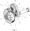
- FIG 1 shows schematically and exemplarily an embodiment of a transmission system 10 for a vehicle (not illustrated).
- the transmission system 10 comprises a first gear assembly 1, a second gear assembly 2, an intermediate unit 3 and an output gear assembly 4 with an output shaft 41.
- the intermediate unit 3 comprises a first sprocket element 31, a second sprocket element 32 and a coupling element 33.
- a central axis of the first coupling shaft 111 is arranged in parallel to a central axis of the second coupling shaft 221 (shown in Figures 2 and 3 ).
- the first sprocket element 31 and the second sprocket element 32 are spaced apart from each other that their connection is provided only through the coupling element 33 of the intermediate unit 3.
- the first and the second sprocket elements 31, 32 have a form of a profiled wheel with teeth that mesh with a teethed surface the coupling element 33, which is depicted as a belt circumscribing the first sprocket element 31 and the second sprocket element 32.
- the first sprocket element 31 and the second sprocket element 32 have different diameters. More specifically, the first sprocket element 31 is smaller in size than the second sprocket element 32.
- the first sprocket element 31 is connectable to an input shaft 5 of a traction motor of the vehicle (not illustrated) in an axial direction of the first sprocket element 31 to receive an input torque.
- the second sprocket element 32 is arranged radially to the first sprocket element 31 and in communication with the first sprocket element 31 through the coupling element 33 to receive the input torque.
- the torque transfer to the output shaft 41 of the output gear assembly 4 can take place from two torque transfer pathways; namely through the first gear assembly 1 or the second gear assembly 2. More specifically, the first gear assembly 1 is connectable to the second sprocket element 32 coaxially to convert the input torque to a first output torque and the second gear assembly 2 is connectable to the first sprocket element 31 coaxially to convert the input torque to a second output torque. The first output torque and the second output torque are different to each other.
- the output gear assembly 4 is configured to selectively transfer the first output torque from the first gear assembly 1 to the output shaft 41 or the second output torque from the second gear assembly 2 to the output shaft 41.
- the first gear assembly 1 comprises a first pinion element 11 engaged with the output gear assembly 4 in a circumferential direction of the output gear assembly 4 and the second gear assembly 2 comprises a second pinion element 22 engaged with the output gear assembly 4 in a circumferential direction of the output gear assembly 4.
- the first pinion element 11 may be connectable to the second sprocket element 32 and the second pinion element 22 may be connectable to the first sprocket element 31.
- the first gear assembly 1 further comprises a first clutch member 34 coaxially positioned at the second sprocket element 32 from one side and attachable to the first pinion element 11 from another side.
- the first clutch member is configured to cause a delivery of the first output torque when being activated.
- the first clutch member 34 is best seen in Figure 2 and will be described in more detail in the following paragraphs.
- Figure 2 shows schematically and exemplarily a cross-sectional detail of the first gear assembly 1 of the transmission system 10.
- the input torque may be transferred from the first sprocket element 31 (not shown in Figure 2 ) via the coupling element 33 to the second sprocket element 32.
- the first pinion element 11 may be connectable to the second sprocket element 32, such that the input torque may be transferred from the second sprocket element 32 to the first pinion element 11, and therefrom to the output gear assembly 4.
- the second sprocket element 32 comprises a recess 35 facing the first pinion element 11, for receiving the first clutch member 34 therein. Accordingly, the recess may be constructed to a size suitable for the second sprocket element to be placed therein.
- the first clutch member 34 has a shape of a disc and the recess has a circular shape and a thickness extending into the second sprocket element 32 for enclosing the disc shaped first clutch member 34 at least partially.
- the recess 35 comprises a through hole 351 concentric with the second sprocket element 32.
- the first gear assembly 1 comprises a first coupling shaft 12 extending coaxially to the second sprocket element 32.
- a central axis of the recess 35 of the second sprocket element 32 is coaxial with a central axis of the first coupling shaft 12.
- the first coupling shaft 12 is depicted as a lay shaft of the transmission system 10.
- the first coupling shaft 12 accommodates the second sprocket element 32 and provides a central axis to the first gear assembly 1.
- the through hole 351 of the recess is aligned with the first coupling shaft 12 for it to rotatably extend therethrough.
- the through hole 351 and the first coupling shaft 12 comprise grooves on the former and matching splines on the latter, for the splines to engage with the grooves to make the second sprocket element 32 rotate with the first coupling shaft 12 (not shown in the Figures).
- the first gear assembly 1 further comprises a first convey shaft 111 concentric to the first coupling shaft 12.
- the first pinion element 11 is mounted on the first convey shaft 111 at an end of the first convey shaft away from the second sprocket element 32.
- the first clutch member 34 may be configured to cause the first convey shaft 111 to engage with the first coupling shaft 12, thereby converting the input torque to the first output torque, when activated. Accordingly, the first clutch member 34 is configured to secure the first convey shaft 111 to the first coupling shaft 12 when activated, for the first convey shaft 111 and the first coupling shaft 12 to rotate together.
- Figure 3 shows schematically and exemplarily a cross-sectional detail of the second gear assembly 2.
- the second gear assembly 2 is connectable to the first sprocket element 31 coaxially to convert the input torque to a second output torque.
- the input torque received from the first sprocket element 31 may be transferred through the second gear assembly 2 to obtain the second output torque.
- the first sprocket element 31 is aligned with the second gear assembly 2 at a common central axis passing through a centre point of each.
- the second gear assembly 2 comprises a second clutch member 21 at a side of the second pinion element 22 opposite to the first sprocket element 31.
- the second clutch member 21, the second pinion element 22 and the first sprocket element 31 have a common central axis.
- the second clutch member 21 may be configured to cause a delivery of the second output torque when being activated.
- the second clutch member 21 is depicted as a dry friction clutch comprising multiple friction elements 210 inside a carrier element 211.
- An elastic element 212 is arranged on the carrier element 211 at a side opposite to the second pinion element 22.
- the elastic element 212 is depicted as a diaphragm spring.
- the second gear assembly 2 comprises a second coupling shaft 221 extending coaxially to the first sprocket element 31.
- the second coupling shaft 221 is concentrically engaged with the carrier element 211 of the second clutch member 21.
- the input shaft 5 is arranged concentrically inside the second coupling shaft 221.
- the first sprocket element 31 comprises a concentrically extending second through hole 311 for the input shaft 5 to rotatably extend therethrough.
- the input shaft 5 is freely rotatable inside the second coupling shaft 221 when the second clutch member 21 is not activated (inactive).
- the second pinion element 22 is mounted on the second coupling shaft 221.
- the second clutch member 21 may be configured to cause the second coupling shaft 221 to engage with the input shaft 5, thereby converting the input torque to the second output torque, when activated.
- a computer program may be stored/distributed on a suitable medium such as an optical storage medium or a solid-state medium supplied together with or as part of other hardware, but may also be distributed in other forms, such as via the Internet or other wired or wireless telecommunication systems. Any reference signs in the claims should not be construed as limiting the scope of the claims.
Landscapes
- Engineering & Computer Science (AREA)
- General Engineering & Computer Science (AREA)
- Mechanical Engineering (AREA)
- Chemical & Material Sciences (AREA)
- Combustion & Propulsion (AREA)
- Transportation (AREA)
- Structure Of Transmissions (AREA)
Priority Applications (3)
| Application Number | Priority Date | Filing Date | Title |
|---|---|---|---|
| EP23152621.1A EP4403796B1 (de) | 2023-01-20 | 2023-01-20 | Getriebesystem für ein fahrzeug und elektrofahrzeug mit einem getriebesystem |
| US18/408,757 US20240246526A1 (en) | 2023-01-20 | 2024-01-10 | Transmission system for a vehicle and an electric vehicle comprising a transmission system |
| CN202410056546.2A CN118375708A (zh) | 2023-01-20 | 2024-01-15 | 用于车辆的传动系统和包括传动系统的电动车辆 |
Applications Claiming Priority (1)
| Application Number | Priority Date | Filing Date | Title |
|---|---|---|---|
| EP23152621.1A EP4403796B1 (de) | 2023-01-20 | 2023-01-20 | Getriebesystem für ein fahrzeug und elektrofahrzeug mit einem getriebesystem |
Publications (2)
| Publication Number | Publication Date |
|---|---|
| EP4403796A1 true EP4403796A1 (de) | 2024-07-24 |
| EP4403796B1 EP4403796B1 (de) | 2025-08-06 |
Family
ID=85018358
Family Applications (1)
| Application Number | Title | Priority Date | Filing Date |
|---|---|---|---|
| EP23152621.1A Active EP4403796B1 (de) | 2023-01-20 | 2023-01-20 | Getriebesystem für ein fahrzeug und elektrofahrzeug mit einem getriebesystem |
Country Status (3)
| Country | Link |
|---|---|
| US (1) | US20240246526A1 (de) |
| EP (1) | EP4403796B1 (de) |
| CN (1) | CN118375708A (de) |
Citations (2)
| Publication number | Priority date | Publication date | Assignee | Title |
|---|---|---|---|---|
| US20110088509A1 (en) * | 2009-07-17 | 2011-04-21 | Gm Global Technology Operations, Inc. | Double-clutch transmission for vehicles |
| DE102019132224A1 (de) * | 2019-11-28 | 2021-06-02 | Schaeffler Technologies AG & Co. KG | Schaltbarer Antrieb III |
Family Cites Families (9)
| Publication number | Priority date | Publication date | Assignee | Title |
|---|---|---|---|---|
| US5078660A (en) * | 1991-04-23 | 1992-01-07 | New Venture Gear, Inc. | Transfer case limited slip planetary differential |
| DE19724490A1 (de) * | 1996-06-12 | 1997-12-18 | Ntn Toyo Bearing Co Ltd | Rotationsübertragungsvorrichtung |
| US6082480A (en) * | 1997-06-11 | 2000-07-04 | Ntn Corporation | Rotation transmission device |
| US6267701B1 (en) * | 1998-09-21 | 2001-07-31 | Borgwarner Inc. | Sprocket for multiple axis phased chain systems |
| US6676557B2 (en) * | 2001-01-23 | 2004-01-13 | Black & Decker Inc. | First stage clutch |
| US7886634B2 (en) * | 2007-09-12 | 2011-02-15 | Walters Manufacturing, Inc. | Automatic transmission arrangement for a motorcycle |
| US8328674B2 (en) * | 2010-01-25 | 2012-12-11 | GM Global Technology Operations LLC | Hybrid powertrain with single motor/generator connected to final drive assembly and method of assembly |
| US10982745B2 (en) * | 2019-01-15 | 2021-04-20 | GM Global Technology Operations LLC | Planetary differential drive system |
| US11236804B2 (en) * | 2020-02-19 | 2022-02-01 | Dana Automotive Systems Group, Llc | Electric drive axle system with removable planetary gear assembly |
-
2023
- 2023-01-20 EP EP23152621.1A patent/EP4403796B1/de active Active
-
2024
- 2024-01-10 US US18/408,757 patent/US20240246526A1/en active Pending
- 2024-01-15 CN CN202410056546.2A patent/CN118375708A/zh active Pending
Patent Citations (2)
| Publication number | Priority date | Publication date | Assignee | Title |
|---|---|---|---|---|
| US20110088509A1 (en) * | 2009-07-17 | 2011-04-21 | Gm Global Technology Operations, Inc. | Double-clutch transmission for vehicles |
| DE102019132224A1 (de) * | 2019-11-28 | 2021-06-02 | Schaeffler Technologies AG & Co. KG | Schaltbarer Antrieb III |
Also Published As
| Publication number | Publication date |
|---|---|
| US20240246526A1 (en) | 2024-07-25 |
| EP4403796B1 (de) | 2025-08-06 |
| CN118375708A (zh) | 2024-07-23 |
Similar Documents
| Publication | Publication Date | Title |
|---|---|---|
| TWI822784B (zh) | 用於自行車或電動自行車之行星齒輪結構的踩踏軸承齒輪箱 | |
| EP3898397B1 (de) | Freilaufkupplung und ein mehrganggetriebesystem mit einer solchen freilaufkupplung | |
| US10807467B2 (en) | Epicyclic gearbox | |
| US5308295A (en) | Planetary gear system for automatic transmission | |
| CN102770338A (zh) | 换挡装置和传动单元 | |
| JP2000135931A (ja) | モジュ―ル構造の車輛用トランスミッション | |
| US12270463B1 (en) | Electric drive system for a motor vehicle | |
| US6468177B2 (en) | Power train for automatic transmissions | |
| EP2964977A1 (de) | Multimodale kupplungen für vorwärts-/rückwärtsplanetengetriebe | |
| KR960005316B1 (ko) | 자동 변속기 | |
| US10876601B2 (en) | Method of assembling a transmission including planetary gear thrust containment | |
| EP4403796A1 (de) | Getriebesystem für ein fahrzeug und elektrofahrzeug mit einem getriebesystem | |
| US10787071B2 (en) | Lockup clutch for powersplit hybrid transmission | |
| KR102873965B1 (ko) | 차동 장치 | |
| EP4119374A1 (de) | Antriebsstrang für ein elektrofahrzeug | |
| EP3733437B1 (de) | Getriebe, einzelkupplungsantriebsstrangsystem und verfahren zum betreiben eines einzelkupplungsantriebsstrangsystems | |
| CN113153991A (zh) | 动力传递装置 | |
| JP2012040941A (ja) | 電動補助自転車 | |
| CN113165496B (zh) | 车辆动力传动系统 | |
| EP4295060A1 (de) | Antriebsstrang für ein elektrofahrzeug | |
| RU2065381C1 (ru) | Главный редуктор вертолета | |
| CN114746672A (zh) | 多速行星式变速器 | |
| KR102544720B1 (ko) | 하중 분산 디바이스 | |
| CN223934528U (zh) | 一种双电机电驱动装置及车辆 | |
| CN219139734U (zh) | 减速机构、轮毂电机及电动自行车 |
Legal Events
| Date | Code | Title | Description |
|---|---|---|---|
| PUAI | Public reference made under article 153(3) epc to a published international application that has entered the european phase |
Free format text: ORIGINAL CODE: 0009012 |
|
| STAA | Information on the status of an ep patent application or granted ep patent |
Free format text: STATUS: REQUEST FOR EXAMINATION WAS MADE |
|
| 17P | Request for examination filed |
Effective date: 20231107 |
|
| AK | Designated contracting states |
Kind code of ref document: A1 Designated state(s): AL AT BE BG CH CY CZ DE DK EE ES FI FR GB GR HR HU IE IS IT LI LT LU LV MC ME MK MT NL NO PL PT RO RS SE SI SK SM TR |
|
| GRAP | Despatch of communication of intention to grant a patent |
Free format text: ORIGINAL CODE: EPIDOSNIGR1 |
|
| STAA | Information on the status of an ep patent application or granted ep patent |
Free format text: STATUS: GRANT OF PATENT IS INTENDED |
|
| RIC1 | Information provided on ipc code assigned before grant |
Ipc: F16H 7/06 20060101ALI20250211BHEP Ipc: F16H 7/02 20060101ALI20250211BHEP Ipc: B60K 1/00 20060101ALI20250211BHEP Ipc: F16H 37/02 20060101ALI20250211BHEP Ipc: F16H 3/10 20060101AFI20250211BHEP |
|
| INTG | Intention to grant announced |
Effective date: 20250228 |
|
| GRAS | Grant fee paid |
Free format text: ORIGINAL CODE: EPIDOSNIGR3 |
|
| GRAA | (expected) grant |
Free format text: ORIGINAL CODE: 0009210 |
|
| STAA | Information on the status of an ep patent application or granted ep patent |
Free format text: STATUS: THE PATENT HAS BEEN GRANTED |
|
| AK | Designated contracting states |
Kind code of ref document: B1 Designated state(s): AL AT BE BG CH CY CZ DE DK EE ES FI FR GB GR HR HU IE IS IT LI LT LU LV MC ME MK MT NL NO PL PT RO RS SE SI SK SM TR |
|
| REG | Reference to a national code |
Ref country code: GB Ref legal event code: FG4D |
|
| REG | Reference to a national code |
Ref country code: CH Ref legal event code: EP |
|
| REG | Reference to a national code |
Ref country code: DE Ref legal event code: R096 Ref document number: 602023005300 Country of ref document: DE |
|
| REG | Reference to a national code |
Ref country code: IE Ref legal event code: FG4D |
|
| P01 | Opt-out of the competence of the unified patent court (upc) registered |
Free format text: CASE NUMBER: UPC_APP_2608_4403796/2025 Effective date: 20250806 |
|
| REG | Reference to a national code |
Ref country code: NL Ref legal event code: MP Effective date: 20250806 |
|
| PG25 | Lapsed in a contracting state [announced via postgrant information from national office to epo] |
Ref country code: IS Free format text: LAPSE BECAUSE OF FAILURE TO SUBMIT A TRANSLATION OF THE DESCRIPTION OR TO PAY THE FEE WITHIN THE PRESCRIBED TIME-LIMIT Effective date: 20251206 |
|
| PG25 | Lapsed in a contracting state [announced via postgrant information from national office to epo] |
Ref country code: NO Free format text: LAPSE BECAUSE OF FAILURE TO SUBMIT A TRANSLATION OF THE DESCRIPTION OR TO PAY THE FEE WITHIN THE PRESCRIBED TIME-LIMIT Effective date: 20251106 |
|
| REG | Reference to a national code |
Ref country code: LT Ref legal event code: MG9D |
|
| PG25 | Lapsed in a contracting state [announced via postgrant information from national office to epo] |
Ref country code: PT Free format text: LAPSE BECAUSE OF FAILURE TO SUBMIT A TRANSLATION OF THE DESCRIPTION OR TO PAY THE FEE WITHIN THE PRESCRIBED TIME-LIMIT Effective date: 20251209 |
|
| PG25 | Lapsed in a contracting state [announced via postgrant information from national office to epo] |
Ref country code: FI Free format text: LAPSE BECAUSE OF FAILURE TO SUBMIT A TRANSLATION OF THE DESCRIPTION OR TO PAY THE FEE WITHIN THE PRESCRIBED TIME-LIMIT Effective date: 20250806 |
|
| PG25 | Lapsed in a contracting state [announced via postgrant information from national office to epo] |
Ref country code: HR Free format text: LAPSE BECAUSE OF FAILURE TO SUBMIT A TRANSLATION OF THE DESCRIPTION OR TO PAY THE FEE WITHIN THE PRESCRIBED TIME-LIMIT Effective date: 20250806 Ref country code: NL Free format text: LAPSE BECAUSE OF FAILURE TO SUBMIT A TRANSLATION OF THE DESCRIPTION OR TO PAY THE FEE WITHIN THE PRESCRIBED TIME-LIMIT Effective date: 20250806 |
|
| PGFP | Annual fee paid to national office [announced via postgrant information from national office to epo] |
Ref country code: FR Payment date: 20251217 Year of fee payment: 4 |
|
| PG25 | Lapsed in a contracting state [announced via postgrant information from national office to epo] |
Ref country code: GR Free format text: LAPSE BECAUSE OF FAILURE TO SUBMIT A TRANSLATION OF THE DESCRIPTION OR TO PAY THE FEE WITHIN THE PRESCRIBED TIME-LIMIT Effective date: 20251107 |
|
| PG25 | Lapsed in a contracting state [announced via postgrant information from national office to epo] |
Ref country code: SE Free format text: LAPSE BECAUSE OF FAILURE TO SUBMIT A TRANSLATION OF THE DESCRIPTION OR TO PAY THE FEE WITHIN THE PRESCRIBED TIME-LIMIT Effective date: 20250806 |
|
| PG25 | Lapsed in a contracting state [announced via postgrant information from national office to epo] |
Ref country code: LV Free format text: LAPSE BECAUSE OF FAILURE TO SUBMIT A TRANSLATION OF THE DESCRIPTION OR TO PAY THE FEE WITHIN THE PRESCRIBED TIME-LIMIT Effective date: 20250806 |
|
| PG25 | Lapsed in a contracting state [announced via postgrant information from national office to epo] |
Ref country code: PL Free format text: LAPSE BECAUSE OF FAILURE TO SUBMIT A TRANSLATION OF THE DESCRIPTION OR TO PAY THE FEE WITHIN THE PRESCRIBED TIME-LIMIT Effective date: 20250806 Ref country code: BG Free format text: LAPSE BECAUSE OF FAILURE TO SUBMIT A TRANSLATION OF THE DESCRIPTION OR TO PAY THE FEE WITHIN THE PRESCRIBED TIME-LIMIT Effective date: 20250806 |
|
| PG25 | Lapsed in a contracting state [announced via postgrant information from national office to epo] |
Ref country code: RS Free format text: LAPSE BECAUSE OF FAILURE TO SUBMIT A TRANSLATION OF THE DESCRIPTION OR TO PAY THE FEE WITHIN THE PRESCRIBED TIME-LIMIT Effective date: 20251106 |
|
| PG25 | Lapsed in a contracting state [announced via postgrant information from national office to epo] |
Ref country code: ES Free format text: LAPSE BECAUSE OF FAILURE TO SUBMIT A TRANSLATION OF THE DESCRIPTION OR TO PAY THE FEE WITHIN THE PRESCRIBED TIME-LIMIT Effective date: 20250806 |
|
| REG | Reference to a national code |
Ref country code: AT Ref legal event code: MK05 Ref document number: 1822153 Country of ref document: AT Kind code of ref document: T Effective date: 20250806 |
|
| PG25 | Lapsed in a contracting state [announced via postgrant information from national office to epo] |
Ref country code: SM Free format text: LAPSE BECAUSE OF FAILURE TO SUBMIT A TRANSLATION OF THE DESCRIPTION OR TO PAY THE FEE WITHIN THE PRESCRIBED TIME-LIMIT Effective date: 20250806 |
|
| PG25 | Lapsed in a contracting state [announced via postgrant information from national office to epo] |
Ref country code: DK Free format text: LAPSE BECAUSE OF FAILURE TO SUBMIT A TRANSLATION OF THE DESCRIPTION OR TO PAY THE FEE WITHIN THE PRESCRIBED TIME-LIMIT Effective date: 20250806 |
|
| PGFP | Annual fee paid to national office [announced via postgrant information from national office to epo] |
Ref country code: DE Payment date: 20251217 Year of fee payment: 4 |
|
| PG25 | Lapsed in a contracting state [announced via postgrant information from national office to epo] |
Ref country code: AT Free format text: LAPSE BECAUSE OF FAILURE TO SUBMIT A TRANSLATION OF THE DESCRIPTION OR TO PAY THE FEE WITHIN THE PRESCRIBED TIME-LIMIT Effective date: 20250806 |
|
| PG25 | Lapsed in a contracting state [announced via postgrant information from national office to epo] |
Ref country code: IT Free format text: LAPSE BECAUSE OF FAILURE TO SUBMIT A TRANSLATION OF THE DESCRIPTION OR TO PAY THE FEE WITHIN THE PRESCRIBED TIME-LIMIT Effective date: 20250806 |
|
| PG25 | Lapsed in a contracting state [announced via postgrant information from national office to epo] |
Ref country code: CZ Free format text: LAPSE BECAUSE OF FAILURE TO SUBMIT A TRANSLATION OF THE DESCRIPTION OR TO PAY THE FEE WITHIN THE PRESCRIBED TIME-LIMIT Effective date: 20250806 |
|
| PG25 | Lapsed in a contracting state [announced via postgrant information from national office to epo] |
Ref country code: EE Free format text: LAPSE BECAUSE OF FAILURE TO SUBMIT A TRANSLATION OF THE DESCRIPTION OR TO PAY THE FEE WITHIN THE PRESCRIBED TIME-LIMIT Effective date: 20250806 Ref country code: SK Free format text: LAPSE BECAUSE OF FAILURE TO SUBMIT A TRANSLATION OF THE DESCRIPTION OR TO PAY THE FEE WITHIN THE PRESCRIBED TIME-LIMIT Effective date: 20250806 |