EP4403762A1 - Verfahren zum einstellen einer brennkraftmaschine und brennkraftmaschine - Google Patents
Verfahren zum einstellen einer brennkraftmaschine und brennkraftmaschine Download PDFInfo
- Publication number
- EP4403762A1 EP4403762A1 EP24151792.9A EP24151792A EP4403762A1 EP 4403762 A1 EP4403762 A1 EP 4403762A1 EP 24151792 A EP24151792 A EP 24151792A EP 4403762 A1 EP4403762 A1 EP 4403762A1
- Authority
- EP
- European Patent Office
- Prior art keywords
- air
- value
- advance angle
- torque
- piston
- Prior art date
- Legal status (The legal status is an assumption and is not a legal conclusion. Google has not performed a legal analysis and makes no representation as to the accuracy of the status listed.)
- Pending
Links
Images

Classifications
-
- F—MECHANICAL ENGINEERING; LIGHTING; HEATING; WEAPONS; BLASTING
- F02—COMBUSTION ENGINES; HOT-GAS OR COMBUSTION-PRODUCT ENGINE PLANTS
- F02D—CONTROLLING COMBUSTION ENGINES
- F02D37/00—Non-electrical conjoint control of two or more functions of engines, not otherwise provided for
- F02D37/02—Non-electrical conjoint control of two or more functions of engines, not otherwise provided for one of the functions being ignition
-
- F—MECHANICAL ENGINEERING; LIGHTING; HEATING; WEAPONS; BLASTING
- F02—COMBUSTION ENGINES; HOT-GAS OR COMBUSTION-PRODUCT ENGINE PLANTS
- F02D—CONTROLLING COMBUSTION ENGINES
- F02D43/00—Conjoint electrical control of two or more functions, e.g. ignition, fuel-air mixture, recirculation, supercharging or exhaust-gas treatment
- F02D43/04—Conjoint electrical control of two or more functions, e.g. ignition, fuel-air mixture, recirculation, supercharging or exhaust-gas treatment using only digital means
-
- F—MECHANICAL ENGINEERING; LIGHTING; HEATING; WEAPONS; BLASTING
- F01—MACHINES OR ENGINES IN GENERAL; ENGINE PLANTS IN GENERAL; STEAM ENGINES
- F01L—CYCLICALLY OPERATING VALVES FOR MACHINES OR ENGINES
- F01L1/00—Valve-gear or valve arrangements, e.g. lift-valve gear
- F01L1/34—Valve-gear or valve arrangements, e.g. lift-valve gear characterised by the provision of means for changing the timing of the valves without changing the duration of opening and without affecting the magnitude of the valve lift
-
- F—MECHANICAL ENGINEERING; LIGHTING; HEATING; WEAPONS; BLASTING
- F02—COMBUSTION ENGINES; HOT-GAS OR COMBUSTION-PRODUCT ENGINE PLANTS
- F02D—CONTROLLING COMBUSTION ENGINES
- F02D41/00—Electrical control of supply of combustible mixture or its constituents
- F02D41/0002—Controlling intake air
-
- F—MECHANICAL ENGINEERING; LIGHTING; HEATING; WEAPONS; BLASTING
- F02—COMBUSTION ENGINES; HOT-GAS OR COMBUSTION-PRODUCT ENGINE PLANTS
- F02D—CONTROLLING COMBUSTION ENGINES
- F02D41/00—Electrical control of supply of combustible mixture or its constituents
- F02D41/008—Controlling each cylinder individually
- F02D41/0085—Balancing of cylinder outputs, e.g. speed, torque or air-fuel ratio
-
- F—MECHANICAL ENGINEERING; LIGHTING; HEATING; WEAPONS; BLASTING
- F02—COMBUSTION ENGINES; HOT-GAS OR COMBUSTION-PRODUCT ENGINE PLANTS
- F02D—CONTROLLING COMBUSTION ENGINES
- F02D41/00—Electrical control of supply of combustible mixture or its constituents
- F02D41/24—Electrical control of supply of combustible mixture or its constituents characterised by the use of digital means
- F02D41/26—Electrical control of supply of combustible mixture or its constituents characterised by the use of digital means using computer, e.g. microprocessor
- F02D41/28—Interface circuits
-
- F—MECHANICAL ENGINEERING; LIGHTING; HEATING; WEAPONS; BLASTING
- F02—COMBUSTION ENGINES; HOT-GAS OR COMBUSTION-PRODUCT ENGINE PLANTS
- F02P—IGNITION, OTHER THAN COMPRESSION IGNITION, FOR INTERNAL-COMBUSTION ENGINES; TESTING OF IGNITION TIMING IN COMPRESSION-IGNITION ENGINES
- F02P5/00—Advancing or retarding ignition; Control therefor
- F02P5/04—Advancing or retarding ignition; Control therefor automatically, as a function of the working conditions of the engine or vehicle or of the atmospheric conditions
- F02P5/145—Advancing or retarding ignition; Control therefor automatically, as a function of the working conditions of the engine or vehicle or of the atmospheric conditions using electrical means
- F02P5/15—Digital data processing
-
- F—MECHANICAL ENGINEERING; LIGHTING; HEATING; WEAPONS; BLASTING
- F02—COMBUSTION ENGINES; HOT-GAS OR COMBUSTION-PRODUCT ENGINE PLANTS
- F02D—CONTROLLING COMBUSTION ENGINES
- F02D41/00—Electrical control of supply of combustible mixture or its constituents
- F02D41/24—Electrical control of supply of combustible mixture or its constituents characterised by the use of digital means
- F02D41/26—Electrical control of supply of combustible mixture or its constituents characterised by the use of digital means using computer, e.g. microprocessor
- F02D41/28—Interface circuits
- F02D2041/286—Interface circuits comprising means for signal processing
- F02D2041/288—Interface circuits comprising means for signal processing for performing a transformation into the frequency domain, e.g. Fourier transformation
-
- F—MECHANICAL ENGINEERING; LIGHTING; HEATING; WEAPONS; BLASTING
- F02—COMBUSTION ENGINES; HOT-GAS OR COMBUSTION-PRODUCT ENGINE PLANTS
- F02D—CONTROLLING COMBUSTION ENGINES
- F02D2200/00—Input parameters for engine control
- F02D2200/02—Input parameters for engine control the parameters being related to the engine
- F02D2200/10—Parameters related to the engine output, e.g. engine torque or engine speed
- F02D2200/101—Engine speed
Definitions
- This invention relates to a method to adjust an internal combustion engine.
- This invention also relates to an internal combustion engine.
- Each cylinder also comprises, in a known way, a corresponding head defining, with the corresponding piston, a corresponding volume chamber than can be varied as a result of the piston's sliding.
- each piston can slide inside the corresponding cylinder between a relative bottom dead centre and a relative top dead centre.
- the volume of the chamber assumes the maximum value.
- the volume of the chamber assumes the minimum value.
- the internal combustion engine also comprises, for each cylinder and corresponding piston:
- the pressure acting on each piston has a value that can vary as the rotation angle of the drive shaft, i.e. the angle between a direction integral with the drive shaft and a fixed direction, varies.
- the torque delivered to the drive shaft from a single cylinder and from the corresponding piston also has a value that can vary as the angle of the drive shaft varies.
- the resulting torque on the drive shaft corresponds to the sum of the torque applied by the individual cylinders and corresponding pistons, and also has a trend that can vary as the rotation angle of the drive shaft varies.
- thermodynamic cycles of the individual cylinders By suitably staggering the thermodynamic cycles of the individual cylinders, a resulting torque trend can be obtained that is more regular as the rotation angle of the drive shaft varies.
- variable trend of the resulting torque corresponds to the presence of a basic oscillation frequency corresponding to the frequency of the thermodynamic cycles performed in the cylinders and the secondary frequencies corresponding to whole multiples of the basic oscillation frequency.
- the order of the oscillation frequency corresponds to half of the number of events for every two complete rotations of the drive shaft corresponding to the execution of a complete thermodynamic cycle.
- an oscillation frequency equal to double the rotation frequency of the drive shaft is identified as a frequency of the second order.
- the one with a total of 12 cylinders, with an angle of 60 degrees between the banks, each comprising six cylinders, is especially widely used in sports or race cars.
- the torque has particularly significant amplitudes at the half order, third order, and sixth order.
- the need to reduce the amplitude of the third order is felt in the sector, in order to limit the irregular nature of the torque, reduce the overall vibrations associated with the operation of the internal combustion engine, and make the noise generated by this operation more regular, especially at an idle speed.
- the purpose of this invention is to produce a method to adjust an internal combustion engine, which makes it possible to meet the need mentioned above.
- This invention also relates to an internal combustion engine according to what is defined by claim 13.
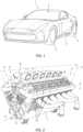
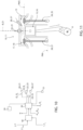
- reference number 1 indicates a motor vehicle comprising a body 2 defining a passenger compartment 3 and multiple wheels 4, 5.
- the motor vehicle 1 comprises an internal combustion engine 6 illustrated in Figure 2 and designed to provide the torque to the wheels 4, 5.
- the internal combustion engine 6 comprises:
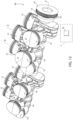
- Each bank 8, 9 defines, in the case illustrated, six respective cylinders 10, 11.
- the banks 8, 9 have respective extension directions parallel to the axis A and respective midplanes P, Q that are orthogonal to the axis A and contain the above-mentioned extension directions.
- the planes P, Q are parallel to respective axes B, D of corresponding cylinders 10, 11.
- each cylinder 10, 11 also houses a respective piston 15, 16 so that it can slide along a respective axis B, C.
- the banks 8, 9 are symmetrically arranged in relation to the axis A and form a V converging towards the axis A.
- the axes B, C lie on corresponding planes symmetrically arranged in relation to the axis A and form the V converging towards the axis A.
- the internal combustion engine 6 thus produces a V12 configuration.
- an angle ⁇ between the axes D and the corresponding axes C is 65 degrees.
- each cylinder 10, 11 also comprises a corresponding head 13.
- Each piston 15, 16 and the head 13 of the corresponding cylinder 10, 11 define a corresponding, variable-volume chamber 17, 18.
- each piston 15, 16 can slide inside the corresponding cylinder 10, 11 between a respective bottom dead centre PMI and a respective top dead centre PMS.
- the volume of the chamber 17, 18 assumes the maximum value.
- the volume of the chamber 17, 18 assumes the minimum value.
- Each cylinder 10, 11 also comprises ( Figure 11 ):
- the internal combustion engine 6 is a four-stroke engine.
- the angular position of the drive shaft 12 around the axis A is identified by an angle ⁇ defined between a direction integral with the drive shaft 12 and a direction fixed in relation to the base 7.
- the internal combustion engine 6 also comprises a clutch 50 and an accelerator 51 (only schematically illustrated in Figure 10 ) that can be operated by a driver.
- the clutch 50 can be operated by the driver, in a known way, to mechanically uncouple the drive shaft 12 and the wheels 4, 5.
- the accelerator 51 can be operated by the driver to adjust the quantities of air Q1, Q2.
- the internal combustion engine 6 also comprises a transducer 40 designed to generate a signal associated with the angular speed n of the drive shaft 12.
- the transducer 40 is a phonic wheel and comprises:
- the sensor 45 can be optical, capacitive, or inductive.
- the sensor 45 also interacts progressively with each groove or projection 42, as a result of the rotation of the drive shaft 12 and the transducer 40 a number i of times for each complete rotation of the drive shaft 12 around the axis A with an angular speed n.
- the internal combustion engine 6 also comprises a control unit 30 (only schematically illustrated in Figure 10 ) programmed to control the intake valves 20, 21, the injection members 26, 27, the ignition members 22, 23, and the discharge valves 24, 25 according to a predetermined sequence, depending on the angular position of the drive shaft 12.
- a control unit 30 (only schematically illustrated in Figure 10 ) programmed to control the intake valves 20, 21, the injection members 26, 27, the ignition members 22, 23, and the discharge valves 24, 25 according to a predetermined sequence, depending on the angular position of the drive shaft 12.
- the control unit 30 is also operationally connected with the clutch 50 and the accelerator 51.
- thermodynamic cycle is produced that converts part of the thermal energy released by the combustion of the mixture into mechanical energy so as to cause the sliding of the pistons 15, 16 and the application of a corresponding torque C1, C2, C3, C4, C5, C6; C7, C8, C9, C10, C11, C12 on the drive shaft 12.
- the advance angles ⁇ 1*, ⁇ 2* correspond to respective optimal values for which the torque C1, C2, C3, C4, C5, C6, C7, C8, C9, C10, C11, C12 reaches the respective maximum value C1max, C2max, C3max, C4max, C5max, C6max; C7max, C8max, C9max, C10max, C11max, C12max, with an equal angular speed n of the drive shaft 12 and quantity of air Q1, Q2.
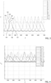
- each cylinder 10, 11 with a graph representing the pressure trend P1, P2, P3, P4, P5, P6; P7, P8, P9, P10, P11, P12 acting on the corresponding piston 15, 16 as a function of the rotation angle ⁇ of the drive shaft 12.
- the trends P1, P2, P3, P4, P5, P6 associated with the cylinders 10 of the bank 8 and P7, P8, P9, P10, P11, P12 associated with the cylinders 11 are the same, due to the fact that the implementations are identical.
- the trends P1, P7, P2, P8, P3, P9, P4, P10, P5, P11, P6, P12 are consecutive to each other with reference to increasing values of the rotation angle ⁇ of the drive shaft 12.
- Each trend P7 (P8, P9, P10, P11, P12) is staggered in relation to the immediately preceding respective trend P1 (P2, P3, P4, P5, P6) by a rotation angle ⁇ of the drive shaft 12 equal to 65 degrees of rotation of the drive shaft 12.
- Each trend P2 (P3, P4, P5, P6) is staggered in relation to the immediately preceding respective trend P7 (P8, P9, P10, P11, P12) by a rotation angle ⁇ of the drive shaft 12 equal to 55 degrees of rotation of the drive shaft 12.
- each trend P1, P2, P3, P4, P5, P6, P7, P8, P9, P10, P11, P12 essentially consists of:
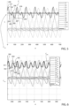
- each cylinder 10, 11 with a graph representing the trend of torque C1, C2, C3, C4, C5, C6; C7, C8, C9, C10, C11, C12 transmitted by the corresponding piston 15, 16 to the drive shaft 12 as a function of the rotation angle ⁇ of the drive shaft 12.
- the torque trends C1, C7, C2, C8, C3, C9, C4, C10, C5, C11, C6, C12 are consecutive and have configurations and offsets that correspond to respective trends P1, P7, P2, P8, P3, P9, P4, P10, P5, P11, P6, P12, as the rotation angle ⁇ of the drive shaft 12 changes.
- the overall torque C on the drive shaft 12 is equal to the sum of the graph torques C1, C2, C3, C4, C5, C6; C7, C8, C9, C10, C11, C12 generated by the cylinders 10, 11.
- This overall torque C has a variable trend as the rotation angle ⁇ of the drive shaft 12 changes, due to the variation in the pressure inside the chambers 17, 18 and the offset between the graphs C1, C2, C3, C4, C5, C6, C7, C8, C9, C10, C11, C12.
- the trend of the resulting torque C basically comprises a regular repetition of:
- the overall torque C has an average value Cavg within a range of 360 degrees of the angle ⁇ of the drive shaft 12.
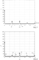
- the temporal trend of the torque C illustrated in Figure 7 can be represented as a sum of multiple sinusoidal signals each having a corresponding frequency f1, f2, .., fn and a corresponding amplitude A1, A2, .. , An.
- each frequency fk and the relative amplitude Ak are identified as corresponding to the k-nth order, i.e. to a frequency equal to k times the rotation frequency n/2 ⁇ corresponding to the rotation speed n of the drive shaft 12.
- the amplitude A3 of the third order corresponding to the frequency f3 is equal to three times the rotation frequency n/2 ⁇ corresponding to the rotation speed n of the drive shaft 12.
- Figure 7 refers to a condition in which the advance angles ⁇ 1, ⁇ 2 are the same and the quantities of air Q1, Q2 are the same and the clutch 50 and/or accelerator 51 is not operated.
- the representation of the resulting torque C has three components having an amplitude A0, A3 and A6 and corresponding frequencies f0, f3 and f6.
- the amplitude A0 corresponds to the average value of the torque C and the non-variable component with the angle ⁇ of the resulting torque C.
- control unit 30 is programmed to:
- the average value Cavg of the resulting torque C and of the corrected resulting torque Cadj remains constant.
- the trends of the torques C1, C2, C3, C4, C5, C6; C7, C8, C9, C10, C11, C12 in Figure 5 are corrected in respective trends C1adj, C2adj, C3adj, C4adj, C5adj, C6adj; C7adj, C8adj, C9adj, C10adj, C11adj, C12adj illustrated in Figure 6 .
- control unit 30 is programmed to:
- control unit 30 is programmed to keep the average values (C1+C2+C3+C4+C5+C6)avg and (C7+C8+C9+C10+C11+C12)avg, associated with respective banks 8, 9 balanced.
- control unit 30 is programmed to:
- the increase of the advance angles ⁇ 2 would lead to an increase in the average value (C7+C8+C9+C10+C11+C12)avg of the sum of the torques C7, C8, C9, C10, C11, C12 delivered by the cylinders 10 and relative pistons 11 of the bank 9.
- this increase is compensated for by the reduction, by basically the same amount, of the torques C7, C8, C9, C10, C11, C12 determined by the increase in the quantity of air Q2.
- control unit 30 is programmed to correct both the advance angle ⁇ 1 and the quantity of air Q1 and the advance angle ⁇ 2 and the quantity of air Q2, so that the average value (C1+C2+C3+C4+C5+C6)avg is different to the average value (C7+C8+C9+C10+C11+C12)avg.
- control unit 30 is programmed to unbalance the average values (C1+C2+C3+C4+C5+C6)avg and (C7+C8+C9+C10+C11+C12)avg, associated with respective banks 8, 9.
- control unit 30 is programmed to only correct the advance angle ⁇ 1 and the quantity of air Q1, leaving both the advance angle ⁇ 2 and the quantity of air Q2 unchanged.
- control unit 30 is programmed to correct the advance angles ⁇ 1 and the quantities of air Q1 of all the cylinders 10, and the advance angles ⁇ 2 and the quantities of air Q2 of all the cylinders 11.
- control unit 30 is also programmed to correct the advance angles ⁇ 1 and the quantities of air Q1 of all the cylinders 10 - and, possibly, also the advance angles ⁇ 2 and the quantities of air Q2 of all the cylinders 11.
- the above-mentioned correction preferably occurs in a condition in which the clutch 50 and/or the accelerator 51 is not operated.
- the above-mentioned correction occurs when the control unit 30 checks that the predetermined operating parameters of the internal combustion engine 6 assume respective desired values.
- the control unit 30 is also programmed not to change the advance angles ⁇ 1, ⁇ 2 and the quantities of air Q1, Q2, when the amplitude A3 is below the value A3 th .
- the control unit 30 is programmed to:
- control unit 30 is programmed to repeat the detection of the amplitude A3 a maximum number l max of times, if at every detection the amplitude A3 is always greater than the value A th .
- control unit 30 is programmed to:
- the control unit 30 is, also, programmed, if the number of times 1 is less than the maximum l max , to:
- the control unit 30 is, finally, programmed to estimate the amplitude A3 based on the value of angular speed n of the drive shaft 12 estimated thanks to a measurement made by the phonic wheel transducer 40.
- the temporal trend of the angular speed n of the drive shaft 12 can be represented as a sum of multiple sinusoidal signals each having a corresponding frequency f1, f2, .., fk, .. fn and a corresponding amplitude B1, B2,.., Bk, .. , Bn corresponding to the k-nth order, entirely similarly to what is described above with reference to the temporal trend of the resulting torque C.
- the control unit 30 is programmed to:
- control unit 30 is programmed to:
- the control unit 40 is, in particular, programmed to:
- control unit 30 is programmed to control the intake valves 20, 21, the injection members 26, 27, the ignition members 22, 23, and the discharge valves 24, 25 of the respective cylinders 10, 11 according to a predetermined cycle depending on the angular position of the drive shaft 12. During this cycle, the thermal energy released by the combustion of the mixture is converted into mechanical energy transmitted by the pistons 15, 16 and by the latter into the respective torques C1, C2, C3, C4, C5, C6; C7, C8, C9, C10, C11, C12 transmitted to the drive shaft 12.
- control unit 30 processes the values of the advance angles ⁇ 1, ⁇ 2 with a period T depending on the number of cylinders 10, 11.
- the graphs C1, C2, C3, C4, C5, C6, C7, C8, C9, C10, C11, C12 of the torque transmitted by the pistons 15, 16 to the drive shaft 12 are of the type illustrated in Figure 3 and the graphs P1, P2, P3, P4, P5, P6, P7, P8, P9, P10, P11, P12 of the pressures acting on the pistons 15, 16 are of the type illustrated in Figure 5 .
- control unit 30 estimates a value of angular speed n of the shaft 12 via the phonic wheel transducer 40, and estimates the amplitude B3 based on the estimated value of angular speed n.
- control unit 30 measures, at each rotation of the drive shaft 12, multiple measurements n1, n2, .. ni of the rotation speeds n, as the respective grooves or projections 42 pass in front of the sensor 45; and selects a number j greater than 2*k and less than/equal to i of measurements n1, ,, nj among the measurements n1, n2 .. ni, where k is the order of frequency of the amplitudes A3 and B3 equal to three in the example illustrated.
- control unit 30 estimates the value of the rotation speed n of the drive shaft 12 as the average of the measurements n1, n2, .. nj.
- the control unit 30 compares the value of the amplitude B3 with the threshold value B3 th and, if the amplitude B3 is greater than the threshold value B3 th , detects the condition that the amplitude A3 is greater than the relative threshold value A3 th .
- the control unit 30 checks that the values of the advance angles ⁇ 1, ⁇ 2 are located in the segment 151 i.e. they are greater than the respective, optimal advance angles ⁇ 1*, ⁇ 2*, before detecting that the amplitude A3 of the frequency signal f3 is greater than a threshold value A3 th .
- control unit 30 corrects the advance angles ⁇ 1, ⁇ 2 and the quantities of air Q1, Q2 of the respective cylinders 10, 11.
- control unit 30 reduces the advance angles ⁇ 1, ⁇ 2 of the respective cylinders 10, 11 and increases said quantity of air Q1, Q2, so as to keep the value of the resulting torque Cavg constant.
- control unit 30 corrects the advance angles ⁇ 1 ( ⁇ 2) and the quantities of air Q1 (Q2) of all the cylinders 10 (11).
- the trends of the torques C1, C2, C3, C4, C5, C6; C7, C8, C9, C10, C11, C12 in Figure 5 are corrected in the trends C1adj, C2adj, C3adj, C4adj, C5adj, C6adj; C7adj, C8adj, C9adj, C10adj, C11adj, C12adj illustrated in Figure 6 .
- the trend of the corrected resulting torque C adj is periodic with a period of 120 degrees of the rotation angle ⁇ and basically comprises ( Figure 6 ), a periodic repetition of:
- the difference between the values of corrected resulting torque C adj between the maximums 300, 304 is less than the difference between the maximums 202, 206 uncorrected resulting torque C.
- the difference between the values of corrected resulting torque C adj between the minimums 302, 306 is less than the difference between the maximums 204, 208 of the uncorrected resulting torque C.
- the control unit 30 preferably corrects the advance angle ⁇ 1 and the quantity of air Q1, so as to keep the average value (C1+C2+C3+C4+C5+C6)avg of the sum of the torques C1, C2, C3, C4, C5, C6 constant; and corrects the advance angle ⁇ 2 and quantity of air Q2, so as to keep the average value (C7+C6+C9+C10+C11+C12)avg of the sum of the torques C7, C8, C9, C10, C11, C12 constant and equal to the average value (C7+C6+C9+C10+C11+C12)avg of the sum of the torques C7, C8, C9, C10, C11, C12.
- the control unit 30 thus keeps the average values (C1+C2+C3+C4+C5+C6)avg and (C7+C8+C9+C10+C11+C12)avg, associated with respective banks 8, 9, balanced.
- the torque reserve of the cylinders 10 and pistons 15 of the bank 8 is increased.
- the torque reserve of the cylinders 11 and pistons 16 of the bank 9 is reduced.
- control unit 30 corrects both the advance angle ⁇ 1 and the quantity of air Q1 and the advance angle ⁇ 2 and the quantity of air Q2, so that the average value (C1+C2+C3+C4+C5+C6)avg is different to the average value (C7+C8+C9+C10+C11+C12)avg.
- the control unit 30 thus keeps the average values (C1+C2+C3+C4+C5+C6)avg and (C7+C8+C9+C10+C11+C12)avg, associated with respective banks 8, 9, unbalanced.
- control unit 30 only corrects the advance angle ⁇ 1 and the quantity of air Q1, leaving both the advance angle ⁇ 2 and the quantity of air Q2 unchanged.
- the representation using sine waves of the corrected resulting torque Cadj has an amplitude component A3 equal to half of the amplitude A3 of the resulting torque C.
- the control unit 30 repeats the detection of the amplitude A3 a number 1 of times, if the current value of the amplitude A3 is greater than the value A th , and, as a result, corrects the advance angles ⁇ 1, ⁇ 2 and the quantities of air Q1, Q2 of the cylinders 10, 11, until the amplitude A3 is less than the value A th .
- control unit 30 repeats the detection of the amplitude A3 a maximum number l max of times, if at every detection the amplitude A3 is always greater than the threshold value A3 th .
- the control unit 30 also processes the minimum value A3 min between the amplitude values A3 detected greater than the threshold value A3 th , and the minimum values ⁇ 1 min , ⁇ 2 min , Q1 min , Q2 min among the corrected values of advance angles ⁇ 1, ⁇ 2 and minimum quantity of air Q1, Q2 corresponding to the minimum value A3 min .
- control unit 30 operates the intake valves 20, 21 and the ignition members 22, 23, so as to produce the advance angles ⁇ 1 min , ⁇ 2 min and minimum quantity of air Q1 min Q2 min .
- the control unit 30 also detects, if the number of times 1 is less than the maximum l max , whether two consecutive values of A3 are increasing or decreasing.
- control unit 30 continues to operate the intake valves 20, 21 and the ignition members 22, 23, so as to decrease the advance angle ⁇ 1, increase the quantity of air Q1, increase the advance angle ⁇ 2 and decrease the quantity of air Q2.
- control unit 30 continues to operate the intake valves 20, 21 and the ignition members 22, 23 so as to increase the advance angle ⁇ 1, decrease the quantities of air Q1, decrease the advance angle ⁇ 2 and increase the quantities of air Q2.
- the adjustment method according to this invention comprises the steps of:
- This correction exploits the torque reserve of the cylinders 10, 11, i.e. the fact that the torque C1, C2, C3, C4, C5, C6; C7, C8, C9, C10, C11, C12 is less than the relative maximum torque C1 max , C2 max , C3 max , C4 max , C5 max , C6 max , C7 max , C8 max , C9 max , C10 max , C11 max , C12 max before the correction of the advance angles ⁇ 1 ( ⁇ 2) and the first quantity of air Q1 (Q2).
- the corrections of the advance angles ⁇ 1 ( ⁇ 2) and quantity of air Q1 (Q2) of the cylinders 10 (11) do not influence, in any way, the safety and driving perception of the motor vehicle 1.
- control unit 30 increases the advance angles ⁇ 1, reduces the quantities of air Q1, reduces the advance angles ⁇ 1 and increases the quantities of air Q2.
- the control unit 30 estimates the amplitude A3 of the third order of the resulting torque C, based on the amplitude B3 of the third order of the angular speed n.
- the control unit 30 estimates, in addition, the amplitude B3 based on the values n1, n2, .. nj of the angular speed n of the drive shaft 12 measured using the phonic wheel transducer 40.
- the values n1, n2, .., nj are detected as a result of the passage of a number j of grooves or projections 42 of the transducer 40 in front of the sensor 45. Since the number j is greater than double the order k associated with the amplitudes Ak, Bk. In this way, it is possible to correctly sample the signal of angular speed n of frequency k and obtain corresponding information on the amount of the amplitude Ak of the resulting torque C, using the transducer 40 commonly present on the drive shaft 12 and without needing to use special transducers.
- control unit 30 can correct the total torque C also by only acting on the advance angles ⁇ 1 ( ⁇ 2) and quantity of air Q1 of the bank 8 (9) or unbalancing the average values (C1+C2+C3+C4+C5+C6)avg and (C7+C8+C9+C10+C11+C12)avg associated with respective banks 8, 9, it is possible to obtain great flexibility relative to the methods for obtaining corrected resulting torque Cadj depending on the functional and construction peculiarities of the internal combustion engine 6.
- control unit 30 could be programmed to:
- the internal combustion engine 6 could have a number of cylinders 10, 11 other than twelve.
- the internal combustion engine 6 could have a V configuration with an angle between the banks 8, 9 other than 65 degrees.
- the internal combustion engine 6 could even not have a V configuration.
- the method according to the invention would make it possible to detect and correct particularly high amplitudes Ak owing not to a construction peculiarity of the internal combustion engine 6, but to functional anomalies of an internal combustion engine with a different configuration.
- the amplitudes Ak, Bk and the relative frequency fk could be different to the third order.
Landscapes
- Engineering & Computer Science (AREA)
- Mechanical Engineering (AREA)
- General Engineering & Computer Science (AREA)
- Chemical & Material Sciences (AREA)
- Combustion & Propulsion (AREA)
- Signal Processing (AREA)
- Computer Hardware Design (AREA)
- Microelectronics & Electronic Packaging (AREA)
- Electrical Control Of Ignition Timing (AREA)
- Combined Controls Of Internal Combustion Engines (AREA)
Applications Claiming Priority (1)
| Application Number | Priority Date | Filing Date | Title |
|---|---|---|---|
| IT102023000000576A IT202300000576A1 (it) | 2023-01-17 | 2023-01-17 | Metodo di regolazione di un motore a combustione interna e motore a combustione interna |
Publications (1)
| Publication Number | Publication Date |
|---|---|
| EP4403762A1 true EP4403762A1 (de) | 2024-07-24 |
Family
ID=85791914
Family Applications (1)
| Application Number | Title | Priority Date | Filing Date |
|---|---|---|---|
| EP24151792.9A Pending EP4403762A1 (de) | 2023-01-17 | 2024-01-15 | Verfahren zum einstellen einer brennkraftmaschine und brennkraftmaschine |
Country Status (3)
| Country | Link |
|---|---|
| US (1) | US12442346B2 (de) |
| EP (1) | EP4403762A1 (de) |
| IT (1) | IT202300000576A1 (de) |
Citations (5)
| Publication number | Priority date | Publication date | Assignee | Title |
|---|---|---|---|---|
| DE102005047829B3 (de) * | 2005-10-05 | 2007-05-03 | Universität Kassel | Zylindergleichstellung bei Hubkolbenmotoren durch Ausregeln der harmonischen Anteile der Kurbelwellendrehzahl |
| DE102009000088A1 (de) * | 2009-01-08 | 2010-07-29 | Ford Global Technologies, LLC, Dearborn | Anordnung und Verfahren zur Verminderung von Schwingungen eines Verbrennungsmotors |
| DE112009001425B4 (de) * | 2008-06-16 | 2016-07-07 | GM Global Technology Operations LLC (n. d. Ges. d. Staates Delaware) | Verfahren und Vorrichtung zur Kraftstoffsystemdiagnose durch Analyse des Motorkurbelwellen-Drehzahlsignals |
| DE102016219582B3 (de) * | 2016-10-10 | 2017-06-08 | Continental Automotive Gmbh | Verfahren zur kombinierten Identifizierung einer Einlassventilhub-Phasendifferenz und einer Auslassventilhub-Phasendifferenz eines Verbrennungsmotors mit Hilfe von Linien gleicher Amplitude |
| DE102016204269B3 (de) * | 2016-03-15 | 2017-06-22 | Continental Automotive Gmbh | Verfahren zum Gleichstellen von Drehmomentabgaben von wenigstens zwei Zylindern einer Brennkraftmaschine |
Family Cites Families (7)
| Publication number | Priority date | Publication date | Assignee | Title |
|---|---|---|---|---|
| US8473183B2 (en) * | 2010-04-27 | 2013-06-25 | Toyota Jidosha Kabushiki Kaisha | Control device for internal combustion engine |
| JP6077656B2 (ja) * | 2013-11-13 | 2017-02-08 | 本田技研工業株式会社 | 原動機の駆動制御装置及び方法 |
| JP6369630B2 (ja) * | 2015-04-20 | 2018-08-08 | 日産自動車株式会社 | エンジン制御装置及びエンジン制御方法 |
| JP6973111B2 (ja) * | 2018-01-23 | 2021-11-24 | マツダ株式会社 | エンジンの制御方法及びエンジンシステム |
| JP7123302B2 (ja) * | 2018-05-30 | 2022-08-23 | マツダ株式会社 | 車両の制御装置 |
| US10927777B2 (en) * | 2018-06-29 | 2021-02-23 | Transportation Ip Holdings, Llc | Methods and systems for a multi-fuel engine |
| JP7291656B2 (ja) * | 2020-03-30 | 2023-06-15 | 日立Astemo株式会社 | 内燃機関の制御装置 |
-
2023
- 2023-01-17 IT IT102023000000576A patent/IT202300000576A1/it unknown
-
2024
- 2024-01-15 EP EP24151792.9A patent/EP4403762A1/de active Pending
- 2024-01-15 US US18/412,850 patent/US12442346B2/en active Active
Patent Citations (5)
| Publication number | Priority date | Publication date | Assignee | Title |
|---|---|---|---|---|
| DE102005047829B3 (de) * | 2005-10-05 | 2007-05-03 | Universität Kassel | Zylindergleichstellung bei Hubkolbenmotoren durch Ausregeln der harmonischen Anteile der Kurbelwellendrehzahl |
| DE112009001425B4 (de) * | 2008-06-16 | 2016-07-07 | GM Global Technology Operations LLC (n. d. Ges. d. Staates Delaware) | Verfahren und Vorrichtung zur Kraftstoffsystemdiagnose durch Analyse des Motorkurbelwellen-Drehzahlsignals |
| DE102009000088A1 (de) * | 2009-01-08 | 2010-07-29 | Ford Global Technologies, LLC, Dearborn | Anordnung und Verfahren zur Verminderung von Schwingungen eines Verbrennungsmotors |
| DE102016204269B3 (de) * | 2016-03-15 | 2017-06-22 | Continental Automotive Gmbh | Verfahren zum Gleichstellen von Drehmomentabgaben von wenigstens zwei Zylindern einer Brennkraftmaschine |
| DE102016219582B3 (de) * | 2016-10-10 | 2017-06-08 | Continental Automotive Gmbh | Verfahren zur kombinierten Identifizierung einer Einlassventilhub-Phasendifferenz und einer Auslassventilhub-Phasendifferenz eines Verbrennungsmotors mit Hilfe von Linien gleicher Amplitude |
Also Published As
| Publication number | Publication date |
|---|---|
| US12442346B2 (en) | 2025-10-14 |
| IT202300000576A1 (it) | 2024-07-17 |
| US20240240598A1 (en) | 2024-07-18 |
Similar Documents
| Publication | Publication Date | Title |
|---|---|---|
| US9938921B2 (en) | Controller and control method for internal combustion engine | |
| US9903290B2 (en) | Controller and control method for internal combustion engine | |
| US7165517B2 (en) | Control apparatus and method for internal combustion engine with variable compression ratio mechanism | |
| US5462022A (en) | Valve timing control apparatus having cylinder discriminating function | |
| JP5328757B2 (ja) | エンジン制御装置 | |
| US20200300730A1 (en) | Diagnosis apparatus for internal combustion engine | |
| JP2005291182A (ja) | 失火検出装置 | |
| JP2018178736A (ja) | 車両の振動抑制装置 | |
| JP5197528B2 (ja) | エンジン負荷検知装置およびエンジン負荷検知方法 | |
| EP4403762A1 (de) | Verfahren zum einstellen einer brennkraftmaschine und brennkraftmaschine | |
| US7881855B2 (en) | Method for metering fuel into combustion chambers of an internal combustion engine | |
| US7770555B2 (en) | Engine combustion controlling method, device and motorcycle | |
| JP2020007942A (ja) | 弁開閉時期制御装置 | |
| JP6102679B2 (ja) | エンジンの制御装置 | |
| JP2007170203A (ja) | 内燃機関の燃焼変動検出装置 | |
| JP2018123735A (ja) | クランク角度検出装置 | |
| JP4317842B2 (ja) | 圧力状態検出装置の異常判定装置 | |
| JP5053780B2 (ja) | 行程判別手段を備える内燃機関 | |
| JP7726061B2 (ja) | 弁開閉時期制御装置 | |
| JP7375950B2 (ja) | 弁開閉時期制御装置 | |
| CN114753936B (zh) | 车辆的控制装置及车辆的控制方法 | |
| JP6815534B2 (ja) | 内燃機関の制御装置 | |
| JP7543199B2 (ja) | 車両制御装置 | |
| JPH07253042A (ja) | 多気筒内燃機関の制御装置 | |
| JP2009030507A (ja) | 内燃機関の気筒判別装置 |
Legal Events
| Date | Code | Title | Description |
|---|---|---|---|
| PUAI | Public reference made under article 153(3) epc to a published international application that has entered the european phase |
Free format text: ORIGINAL CODE: 0009012 |
|
| STAA | Information on the status of an ep patent application or granted ep patent |
Free format text: STATUS: THE APPLICATION HAS BEEN PUBLISHED |
|
| AK | Designated contracting states |
Kind code of ref document: A1 Designated state(s): AL AT BE BG CH CY CZ DE DK EE ES FI FR GB GR HR HU IE IS IT LI LT LU LV MC ME MK MT NL NO PL PT RO RS SE SI SK SM TR |
|
| STAA | Information on the status of an ep patent application or granted ep patent |
Free format text: STATUS: REQUEST FOR EXAMINATION WAS MADE |
|
| 17P | Request for examination filed |
Effective date: 20250122 |
|
| STAA | Information on the status of an ep patent application or granted ep patent |
Free format text: STATUS: EXAMINATION IS IN PROGRESS |
|
| 17Q | First examination report despatched |
Effective date: 20250401 |