EP4403673A1 - Kathodenvorrichtung für eine aluminiumelektrolysezelle - Google Patents
Kathodenvorrichtung für eine aluminiumelektrolysezelle Download PDFInfo
- Publication number
- EP4403673A1 EP4403673A1 EP22870397.1A EP22870397A EP4403673A1 EP 4403673 A1 EP4403673 A1 EP 4403673A1 EP 22870397 A EP22870397 A EP 22870397A EP 4403673 A1 EP4403673 A1 EP 4403673A1
- Authority
- EP
- European Patent Office
- Prior art keywords
- cathode
- cathode assembly
- composite material
- pot
- belt
- Prior art date
- Legal status (The legal status is an assumption and is not a legal conclusion. Google has not performed a legal analysis and makes no representation as to the accuracy of the status listed.)
- Pending
Links
Images


Classifications
-
- C—CHEMISTRY; METALLURGY
- C25—ELECTROLYTIC OR ELECTROPHORETIC PROCESSES; APPARATUS THEREFOR
- C25C—PROCESSES FOR THE ELECTROLYTIC PRODUCTION, RECOVERY OR REFINING OF METALS; APPARATUS THEREFOR
- C25C3/00—Electrolytic production, recovery or refining of metals by electrolysis of melts
- C25C3/06—Electrolytic production, recovery or refining of metals by electrolysis of melts of aluminium
- C25C3/08—Cell construction, e.g. bottoms, walls, cathodes
- C25C3/10—External supporting frames or structures
-
- C—CHEMISTRY; METALLURGY
- C25—ELECTROLYTIC OR ELECTROPHORETIC PROCESSES; APPARATUS THEREFOR
- C25C—PROCESSES FOR THE ELECTROLYTIC PRODUCTION, RECOVERY OR REFINING OF METALS; APPARATUS THEREFOR
- C25C3/00—Electrolytic production, recovery or refining of metals by electrolysis of melts
- C25C3/06—Electrolytic production, recovery or refining of metals by electrolysis of melts of aluminium
- C25C3/08—Cell construction, e.g. bottoms, walls, cathodes
Definitions
- This invention pertains to aluminium production via electrolysis of molten salts, particularly to the cathode assembly of a reduction cell, and explores the assembly of the upper belt of the longitudinal and end walls of the cathode shell.
- a cathode assembly is usually an assembly that comprises a cathode shell and an internal lining, which enables electrolysis to occur within a cryolite-alumina melt (also known as bath).
- the cathode shell consists of a metal pot including longitudinal and end walls, with base and bearing members (shell stiffening rods, counterforce cradles, and beams, among others), which cover the pot's walls and base, and are typically constructed from steel.
- the cathode shell is lined inside with lining materials (refractory and heat-insulating bricks, carbide-silicon plates and carbon-graphite cathode blocks with steel cathode rods, etc.).
- the cathode shell is engineered to protect the internal lining from any distortions or damage caused by forces generated within the cathode assembly while the reduction cell is in operation. Therefore, it must have the necessary mechanical strength and stiffness to ensure a long service life of the cathode assembly.
- cathode shell Another important function of the cathode shell is to ensure intensive heat removal from the electrolysis process area and dissipation of excess heat into the environment. This contributes to the formation of a layer of solidified cryolite-alumina melt/scale on the inner lined (side) walls of the cathode assembly, which protects them from the effects of aggressive environment and high temperature (within 870-970 °C), thus providing optimal conditions for the electrolytic reduction and protect the side walls from the aggressive effects of bath and electrolytic reduction products.
- a method of cooling an aluminium reduction cell ( US 4087345, C25C 3/08, May 2, 1978 ) containing a cathode shell in the form of a steel pot including vertical (longitudinal and end) walls with a bottom is known.
- Vertical stiffeners (T-beams and/or I-beams) are attached to the walls at certain intervals along the length and width of the shell. The beams have good thermal contact with the walls of the steel pot.
- the walls of the steel pot are encompassed by horizontal stiffeners (T-beams and/or I-beams) all around the outer perimeter, forming a single rigid structure.
- the walls may be additionally covered by bearing members (shell stiffening rods, counterforce cradles).
- vertical air corridors are formed designed for unobstructed passage of air to remove and dissipate heat from the shell walls and vertical stiffeners of the structure.
- the shell walls are cooled by a convective air flow caused by the lifting (Archimedes') force resulting from the air heating in the upper parts (at the melt level) of the vertical air corridors and the resulting temperature difference along the height of the shell walls.
- This makes it possible to increase heat removal by the vertical side walls of the shell and reduce the temperature of the shell walls, thus creating conditions for the formation of a layer of solidified cryolite-alumina melt/scale on the inner lined walls of the cathode assembly.
- the primary shortcoming of the existing method lies in the low efficacy of heat removal and dissipation from the cathode shell due to the limited cooling area and low velocities of convective air flow. Consequently, in this situation, applying a stable and sufficiently thick layer of scale on the inner surface of the side lining becomes problematic. Lack of scale usually results in intensive wear of the side lining, which adversely impacts the service life of the reduction cell.
- a cathode assembly of an aluminium reduction cell (RU 2230834, C25C 3/08, June 20, 2004 ) is known, equipped with a cathode shell, including a metal pot lined from the inside, with longitudinal and end walls and bottom, installed inside a rigid frame formed by transverse shell stiffening rods (bearing members).
- the end walls of the pot are reinforced with stiffening belts formed by vertical and horizontal stiffeners connected with each other by a strapping (bending) sheet.
- the horizontal stiffeners are placed at some distance in the horizontal plane from the vertical end wall, in such a way that vertical air corridors are formed between them with the width of 1/3 to 2/3 of the distance from the end wall of the pot to the strapping sheet, which are intended for the flow of air cooling the shell.
- the vertical stiffening ribs there are vertical steel cooling ribs in the amount of 1-4 pcs. and the height equal to the height of the side lining, preferably the dimensions of the ribs are as follows: thickness 6-8 mm, height 640-650 mm, width 120 mm.
- the known method enables air flow along vertical air corridors through cooling ribs welded to the wall to remove and dissipate heat from the end walls of the cathode shell by natural convective heat exchange with the environment.
- the primary shortcoming of the known solution is that it is proposed to install cooling ribs only on the end walls of the cathode shell, as a result of which heat will be removed more intensively only from the ends of the cathode shell, while the problem with the cooling of the longitudinal walls remains.
- Another shortcoming of this solution is the low efficiency of heat removal from the end wall of the cathode shell, because the heat transfer coefficient increases insignificantly (from about 15 to 25 W/m 2 ⁇ K). This is explained by the presence of a solid flange sheet preventing the free air flow and relatively low thermal conductivity of cooling ribs made of St3 steel with a coefficient of thermal conductivity of 50 W/m-K at 300 °C), so the heat transfer by the ribs is inefficient.
- a method of cooling a reduction cell for aluminium production is known ( US 4608134, C25C 3/08, August 26, 1986 ), containing an external cathode shell, made in the form of a steel pot, with lining enclosed inside it, consisting of refractory and heat-insulating lining materials and carbon-graphite cathode blocks and located on the inner part of the side walls of the cathode shell side part of the lining (carbon-graphite or silicon carbide plates).
- air cavities which communicate with inlets for air intake and outlets equipped with air flow control valves.
- Cooling takes place as follows: cold air drawn from the environment at the sides of the reduction cell is drawn in through the inlets and directed into the air cavities along the side lining, resulting in its cooling, while the hot air flow rate is controlled through the outlets fitted with valves.
- the hot air flow rate is controlled through the outlets fitted with valves.
- a reduction cell for aluminium production is known ( SU 605865, C25C 3/08, May 5, 1978 ), including a metal cathode shell in the form of a steel pot, lined from the inside, the bottom and vertical walls of which are provided with box sections made in the form of airtight cavities. Heat shields made of individual plates are installed in the airtight cavities, and air lines with air distribution valves are connected to them, into which air is blown by a fan or compressor.
- the closest to the proposed invention in terms of technical essence and achieved result is the design of the cathode assembly of the aluminium reduction cell according to the patent RU 2321682, C25C 3/08, April 10, 2008 .
- the assembly comprises a metal pot with a bottom and bearing members covering the walls and bottom of the bath, forming a cathode shell. Inside the cathode shell is the lining and cathode blocks with cathode rods that form the reduction cell cathode.
- the plate rib is fastened to the metal pot using aluminium-steel or copper-steel bimetallic adapters made by explosion welding.
- the steel part of the bimetallic adapter is welded to the walls of the metal pot, and to the aluminium or copper part, plate ribs are welded made of aluminium or aluminium alloy or copper or copper alloy, respectively.
- Regulators designed as pivoting flaps, which control the efficiency of heat removal from the pot walls, are positioned in the upper section of the bearing members.
- a device for forced cooling of the plate ribs in the form of a fan and a blower.
- the device makes it possible to intensify the process of electrolytic aluminium production in an aluminium reduction cell by regulating the efficiency of heat removal, to provide conditions for a stable production process and to increase the service life of the cathode assembly of an aluminium reduction cell.
- the known cathode assembly makes it possible to provide effective heat removal from the reduction cell to the pot side walls and further to the plate ribs, which are cooled by convective heat exchange during air flow caused by the air heating in the space between the ribs and the temperature difference along the height of the pot walls.
- This makes it possible under conditions of intensive operation of the aluminium reduction cell to ensure formation of a stable layer of solidified bath (scale) on the inner surface of the side lining of the cathode assembly, thus increasing the service life of the cathode assembly of the aluminium reduction cell.
- the shortcoming of the cathode assembly in the prototype is that in conditions of an intensive reduction process, a necessary condition for increasing the production efficiency is to ensure the ability to operate the reduction cell with a high temperature of the bath overheating (the difference between the operating temperature and the liquidus temperature) to avoid dross deposition and the formation of crusts on the bottom that decreases the process efficiency and causes related drawbacks. Therefore, the main task is to create a layer of protective scale at overheating above 25 °C (optimally about 40 °C), while the known solution can guarantee scale formation only at overheating of about 20 °C. This is because this design provides efficient heat transfer from the reduction cell to the side walls of the pot, while heat dissipation from the outer surface of the shell and, accordingly, plate ribs is not effective enough for the production process.
- ribs are made of aluminium or aluminium alloy, copper or copper alloy, or special steel, i.e. a material with high thermal conductivity.
- the plate ribs are attached with their ends to the longitudinal and end walls of the metal pot through a bimetallic adapter made by explosion welding or by bolted and/or riveted connection.
- the plate ribs are fixed by means of a welded joint, i.e. the heat is only transferred through the weld leg instead of the entire cross-section of the bimetallic adapter. This ensures a minimum temperature difference of about 30-50 °C.
- the task of the proposed invention is to develop a design of a cathode assembly for an aluminium reduction cell with increased heat dissipation from the upper part of the metal pot sides, capable of operating at overheating above 25 °C.
- the technical result is the solution of the problem, more intensive production of aluminium by reduction (increasing the unit current) in an aluminium reduction cell due to the design of a cathode assembly capable of removing and dissipating the heat energy released in the reduction cell.
- the invention is supplemented by its particular embodiments that contribute to the achievement of the technical result.
- the belt composite material may comprise at least two metal layers, wherein the overall height of the belt is 0.2-0.5 m. If the height is less than 0.2 m, insufficient heat will be removed and dissipated from the belt and the solution will be ineffective. If the height is greater than 0.5 m, the heat removal becomes excessive and as a result cooling will affect the metal area (liquid aluminium), which will negatively impact the reduction process.
- the upper layer (13) of the belt composite material is made of a metal with high thermal conductivity.
- the upper layer (13) of the belt composite material may be made of aluminium or aluminium alloys.
- the upper layer (13) of the belt composite material may be made of copper or copper alloys.
- the belt composite material is made by joining metal layers by pulse welding.
- the belt composite material may comprise an intermediate layer (14) made of titanium.
- Heat removal regulators (17) designed as pivoting flaps (18) may be installed above the bearing members.
- a self-regulating system is provided for.
- Heat removal is regulated by increasing and decreasing the scale thickness.
- forced cooling elements devices
- Forced cooling devices such as fans, may be arranged in the gaps between the bearing members (5).
- the described design of the cathode assembly makes it possible to ensure effective heat removal from the reduction cell to the pot side walls and effectively dissipate heat energy by convective heat exchange during air flow caused by the air heating in the space between the ribs and the temperature difference along the height of the pot walls.
- This makes it possible under conditions of intensive operation of the aluminium reduction cell to ensure formation of a stable layer of solidified bath (scale) on the inner surface of the side lining of the cathode assembly at overheating above 25 °C and to guarantee stable and steady operation of the aluminium reduction cell.
- the invention is supplemented by special cases directed to the problem at hand.
- the cathode assembly is supplemented by that the composite material is made by pulse welding, the compounds obtained are steel/aluminium, steel/copper, and in the case of a titanium (Ti) interlayer, they are steel/titanium/aluminium, steel/titanium/copper.
- Ti titanium
- the titanium layer in composite walls is necessary for operation of the side walls at temperatures above 300 °C to avoid the formation of intermetallides at the boundary of two metals joined by the pulse and degradation of this compound.
- the outer layer of the composite material is made of a metal with a high thermal conductivity coefficient, such as aluminium, copper, bronze or special steel.
- a metal with a high thermal conductivity coefficient such as aluminium, copper, bronze or special steel.
- ⁇ 110-230 W/m ⁇ K
- copper ⁇ 360-390 W/m ⁇ K or copper alloy (bronze, brass, etc.) with thermal conductivity coefficient of approx. 70 to 380 W/m-K
- special steels 55, 60, 65, 70, 20G, 30G, 40G, etc. with thermal conductivity coefficient of approx. 50-80 W/m ⁇ K.
- plate ribs made of material with high coefficient of thermal conductivity are fixed on it in the amount of 3-10 pieces and with the area of 0,03-0,6 m 2 .
- the cathode assembly is supplemented in that to further improve efficiency, the plate ribs may be replaced by fingers (may be in the form of rods, bars, "sticks", etc.) having a much more developed surface for heat dissipation.
- the cathode assembly is supplemented by that in the upper part of the bearing members there are installed regulators of the efficiency of heat removal from the walls of the metal pot designed as pivoting flaps, which make it possible to adjust the scale thickness or adjust its shape depending on seasonal changes in ambient temperature.
- the cathode assembly is supplemented by that a forced cooling device in the form of a fan and a blower is located in the gap between the bearing members.
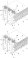
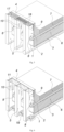
- the cathode assembly of an aluminium reduction cell includes a metal pot 1 having longitudinal and end walls 2, bottom 3 and flange sheet 4; bearing members 5 covering the walls and bottom of the pot; lining 6 enclosed inside the pot 1, cathode blocks 7 with cathode rods 8 forming the cathode of the reduction cell; upper belt 9 made of composite material.
- the flow 10 is created by the lifting (Archimedes') force due to its heating in the space limited by the bearing members 5, as well as by the flow of air due to the difference in its temperature along the height of the walls of the pot 2.
- the metal pot 1 with longitudinal and end walls 2, bottom 3 and flange sheet 4 and bearing members 5 comprising the cathode assembly also participate in the heat exchange.
- Composite material is made by pulse welding, that is pressure welding in which workpieces are welded when they collide with each other due to the detonation of a pyrocharge.
- a movable workpiece which is the upper layer 13 (of a metal different from the base in physical properties, usually softer and less strong) is welded to the base 12 (a fixed steel workpiece).
- an intermediate (barrier) layer 14 of Ti (titanium) 0.5-1.5 mm thick is placed at the interface (flat or dovetail type) to prevent the formation of brittle intermetallides.
- the upper layer 13 of the belt 9 is made of a metal having high thermal conductivity, aluminium, copper, bronze or special steel may be used as such metals.
- the surface of the upper layer 13 may be developed by installing plate ribs 15 made of a metal with high thermal conductivity, which are fixed by welding, brazing or other mechanical means (bolted and/or riveted) and by having previously made a flat surface 13 by milling or installing a spacer, for example made of a fusible heat conducting material, graphite- or silver-based thermal paste, aluminium foil, refractory cement, etc., which will level the uneven surface of the wall.
- a spacer for example made of a fusible heat conducting material, graphite- or silver-based thermal paste, aluminium foil, refractory cement, etc.
- heat removal regulators 17 designed as pivoting flaps 18, can be installed in the aperture 11 above the bearing members 5 to change the open area in the aperture 11. This makes it possible to adjust the scale thickness depending on seasonal changes in the ambient temperature and changes in the reduction cell current.
- a forced cooling device 19 may be installed in the gap between the bearing members 5.
- the device is, for example, a centrifugal fan with a capacity of 1000-2000 m 3 /h. The heat dissipation can thus be increased by a further 30-50%.
- the bottom 3, flange sheet 4 and longitudinal and end walls 2 of the metal pot 1 are made of 12-20 mm thick sheet steel of sufficient ductility and quality.
- lining 6 is placed inside the metal pot 1, consisting of refractory and heat-insulating materials, and cathode blocks 7 with cathode rods 8 installed in them.
- Bearing members 5 covering the walls and bottom of the pot 1 are made in the form of either shell stiffening rods (T- or I-beams) or hinged counterforce cradles (a structure with a box cross-section or two I-beams welded together).
- T- or I-beams shell stiffening rods
- hinged counterforce cradles a structure with a box cross-section or two I-beams welded together.
- a belt 9 made of composite material consisting of 2 or more layers of different metals with a height of 0.2-0.5 m is installed.
- the lower part of the belt is welded to the walls 2, the upper part of the belt is welded to the flange sheet 4, and the upper layer 13 surface is either welded to the bearing members 5 or rests in them, ensuring free contact.
- the belt 9 is manufactured of composite material separately. Pulse welding is a mechanical type of pressure welding in which the joint is made by the explosion-induced collision of the parts to be welded.
- the composite belt material comprises typically a steel base 12, an upper layer 13 of high thermal conductivity material and an intermediate layer 14 of titanium. The intermediate layer 14 is required to be installed when the belt is operated in the device at temperatures greater than 300 °C.
- the greatest efficiency is achieved when the upper layer 13 of the belt 9 of composite material has a developed surface, which is achieved by inserting plate ribs 15 and/or finger ribs 16 made of a highly thermally conductive material such as special steel, aluminium or aluminium alloy, copper or copper alloy.
- the plate rib 15 is made in the form of a rectangle or trapezoid with a height of 300-600 mm, a width of 100-500 mm and a thickness of 6-10 mm. The number of ribs is selected based on the required heat transfer coefficient.
- Replacing the plate ribs 15 with finger ribs 16 increases the heat transfer surface by 20-30% and makes it possible to increase the heat transfer coefficient by 15-20%.
- the heat dissipation coefficient can be reduced by closing the pivoting flaps 18 of the heat removal regulators 17.
- forced cooling devices 19 in the form of a fan and blower may be used, as well as other suitable cooling devices.
- the proposed cathode assembly can provide a stable layer of solidified bath (scale) on the inner surface of the side lining of the cathode assembly at overheating above 25 °C and guarantee stable and steady operation of the aluminium reduction cell.
- the test sample was operated at overheating of 40 °C, in summer (the worst conditions) and there was a minimum layer of protective scale on the walls.
Landscapes
- Chemical & Material Sciences (AREA)
- Engineering & Computer Science (AREA)
- Chemical Kinetics & Catalysis (AREA)
- Electrochemistry (AREA)
- Materials Engineering (AREA)
- Metallurgy (AREA)
- Organic Chemistry (AREA)
- Electrolytic Production Of Metals (AREA)
Applications Claiming Priority (2)
| Application Number | Priority Date | Filing Date | Title |
|---|---|---|---|
| RU2021127241A RU2770602C1 (ru) | 2021-09-16 | 2021-09-16 | Катодное устройство алюминиевого электролизера |
| PCT/RU2022/050227 WO2023043334A1 (ru) | 2021-09-16 | 2022-07-21 | Катодное устройство алюминиевого электролизера |
Publications (2)
| Publication Number | Publication Date |
|---|---|
| EP4403673A1 true EP4403673A1 (de) | 2024-07-24 |
| EP4403673A4 EP4403673A4 (de) | 2026-01-14 |
Family
ID=81255450
Family Applications (1)
| Application Number | Title | Priority Date | Filing Date |
|---|---|---|---|
| EP22870397.1A Pending EP4403673A4 (de) | 2021-09-16 | 2022-07-21 | Kathodenvorrichtung für eine aluminiumelektrolysezelle |
Country Status (6)
| Country | Link |
|---|---|
| US (1) | US20240426014A1 (de) |
| EP (1) | EP4403673A4 (de) |
| CN (1) | CN117940611A (de) |
| CA (1) | CA3231974A1 (de) |
| RU (1) | RU2770602C1 (de) |
| WO (1) | WO2023043334A1 (de) |
Family Cites Families (10)
| Publication number | Priority date | Publication date | Assignee | Title |
|---|---|---|---|---|
| SU605865A1 (ru) | 1976-05-10 | 1978-05-05 | Северо-Западное Отделение Всесоюзного Научно-Исследовательского И Проектноконструкторского Института "Внипиэнергопром" | Электролизер дл получени алюмини |
| US4087345A (en) * | 1977-07-19 | 1978-05-02 | Ardal Og Sunndal Verk A.S. | Potshell for electrolytic aluminum reduction cell |
| US4608134A (en) | 1985-04-22 | 1986-08-26 | Aluminum Company Of America | Hall cell with inert liner |
| FR2842215B1 (fr) * | 2002-07-09 | 2004-08-13 | Pechiney Aluminium | Procede et systeme de refroidissement d'une cuve d'electrolyse pour la production d'aluminium |
| RU2230834C1 (ru) * | 2002-11-10 | 2004-06-20 | Архипов Геннадий Викторович | Катодный кожух алюминиевого электролизера |
| TWI322198B (en) * | 2003-01-22 | 2010-03-21 | Toyo Tanso Co | Electrolytic apparatus for molten salt |
| EP1805349B1 (de) * | 2004-10-21 | 2012-12-26 | BHP Billiton Innovation Pty Ltd | Interne kühlung einer elektrolytischen schmelzzelle |
| RU2321682C2 (ru) * | 2006-05-23 | 2008-04-10 | Общество с ограниченной ответственностью "Русская инжиниринговая компания" | Катодное устройство алюминиевого электролизера |
| EP3221495B1 (de) * | 2014-11-21 | 2020-11-11 | Hatch Ltd. | Flacher aluminiumzellenkasten und verfahren zur erhöhung der produktionskapazität einer aluminiumzellenkastenstrasse |
| GB2572564A (en) * | 2018-04-03 | 2019-10-09 | Dubai Aluminium Pjsc | Potshell for electrolytic cell to be used with the Hall-Heroult process |
-
2021
- 2021-09-16 RU RU2021127241A patent/RU2770602C1/ru active
-
2022
- 2022-07-21 EP EP22870397.1A patent/EP4403673A4/de active Pending
- 2022-07-21 US US18/692,717 patent/US20240426014A1/en active Pending
- 2022-07-21 CA CA3231974A patent/CA3231974A1/en active Pending
- 2022-07-21 WO PCT/RU2022/050227 patent/WO2023043334A1/ru not_active Ceased
- 2022-07-21 CN CN202280062243.0A patent/CN117940611A/zh active Pending
Also Published As
| Publication number | Publication date |
|---|---|
| WO2023043334A1 (ru) | 2023-03-23 |
| RU2770602C1 (ru) | 2022-04-18 |
| US20240426014A1 (en) | 2024-12-26 |
| EP4403673A4 (de) | 2026-01-14 |
| CA3231974A1 (en) | 2023-03-23 |
| CN117940611A (zh) | 2024-04-26 |
Similar Documents
| Publication | Publication Date | Title |
|---|---|---|
| EP1756320B1 (de) | Bei der stahlherstellung verwendetes wärmetauschersystem | |
| US10760854B2 (en) | Adjustable heat exchange apparatus and method of use | |
| MX2011010820A (es) | Placa de enfriamiento para un horno metalurgico. | |
| JP4741599B2 (ja) | 電解製錬槽の内部冷却 | |
| US7537724B2 (en) | Cooling plate for metallurgic furnaces | |
| US6890479B2 (en) | System and method for steel making | |
| US20240426014A1 (en) | Cathode device for an aluminium electrolysis cell | |
| US20180216888A1 (en) | Top loading roof for electric arc, metallurgical or refining furnaces and system thereof | |
| RU2376402C2 (ru) | Способ крепления ребер охлаждения на катодный кожух алюминиевого электролизера | |
| RU2321682C2 (ru) | Катодное устройство алюминиевого электролизера | |
| JP2003279265A (ja) | 電気炉用水冷パネル | |
| RU2308547C1 (ru) | Катодный кожух алюминиевого электролизера | |
| RU208227U1 (ru) | Газосборный колокол алюминиевого электролизера | |
| CN212469742U (zh) | 一种中间包包盖内衬结构 | |
| JP4232604B2 (ja) | 溶湯炉 | |
| JP4304944B2 (ja) | 溶融金属収納容器およびその外壁冷却方法 | |
| AU2005306566B2 (en) | Internal cooling of electrolytic smelting cell | |
| AU2022393598A1 (en) | Interior lining system for an electrolytic cell | |
| BR112019015551B1 (pt) | Método para substituição de uma porção danificada de um teto de forno de um forno metalúrgico ou de refinamento, e, conjunto de teto para um forno metalúrgico ou de refinamento | |
| SE437726B (sv) | Ugnsanordning for smeltning och varmhallning av metall | |
| JP2019184102A (ja) | 金属製錬炉及びその操業方法 |
Legal Events
| Date | Code | Title | Description |
|---|---|---|---|
| STAA | Information on the status of an ep patent application or granted ep patent |
Free format text: STATUS: THE INTERNATIONAL PUBLICATION HAS BEEN MADE |
|
| PUAI | Public reference made under article 153(3) epc to a published international application that has entered the european phase |
Free format text: ORIGINAL CODE: 0009012 |
|
| STAA | Information on the status of an ep patent application or granted ep patent |
Free format text: STATUS: REQUEST FOR EXAMINATION WAS MADE |
|
| 17P | Request for examination filed |
Effective date: 20240308 |
|
| AK | Designated contracting states |
Kind code of ref document: A1 Designated state(s): AL AT BE BG CH CY CZ DE DK EE ES FI FR GB GR HR HU IE IS IT LI LT LU LV MC MK MT NL NO PL PT RO RS SE SI SK SM TR |
|
| DAV | Request for validation of the european patent (deleted) | ||
| DAX | Request for extension of the european patent (deleted) | ||
| A4 | Supplementary search report drawn up and despatched |
Effective date: 20251217 |
|
| RIC1 | Information provided on ipc code assigned before grant |
Ipc: C25C 3/08 20060101AFI20251211BHEP Ipc: C25C 3/10 20060101ALI20251211BHEP |