EP4403395A1 - Tanksystem - Google Patents
Tanksystem Download PDFInfo
- Publication number
- EP4403395A1 EP4403395A1 EP23216295.8A EP23216295A EP4403395A1 EP 4403395 A1 EP4403395 A1 EP 4403395A1 EP 23216295 A EP23216295 A EP 23216295A EP 4403395 A1 EP4403395 A1 EP 4403395A1
- Authority
- EP
- European Patent Office
- Prior art keywords
- tank
- housing
- tensioning
- tank system
- casing
- Prior art date
- Legal status (The legal status is an assumption and is not a legal conclusion. Google has not performed a legal analysis and makes no representation as to the accuracy of the status listed.)
- Withdrawn
Links
Images




Classifications
-
- B—PERFORMING OPERATIONS; TRANSPORTING
- B60—VEHICLES IN GENERAL
- B60K—ARRANGEMENT OR MOUNTING OF PROPULSION UNITS OR OF TRANSMISSIONS IN VEHICLES; ARRANGEMENT OR MOUNTING OF PLURAL DIVERSE PRIME-MOVERS IN VEHICLES; AUXILIARY DRIVES FOR VEHICLES; INSTRUMENTATION OR DASHBOARDS FOR VEHICLES; ARRANGEMENTS IN CONNECTION WITH COOLING, AIR INTAKE, GAS EXHAUST OR FUEL SUPPLY OF PROPULSION UNITS IN VEHICLES
- B60K15/00—Arrangement in connection with fuel supply of combustion engines or other fuel consuming energy converters, e.g. fuel cells; Mounting or construction of fuel tanks
- B60K15/03—Fuel tanks
-
- B—PERFORMING OPERATIONS; TRANSPORTING
- B60—VEHICLES IN GENERAL
- B60K—ARRANGEMENT OR MOUNTING OF PROPULSION UNITS OR OF TRANSMISSIONS IN VEHICLES; ARRANGEMENT OR MOUNTING OF PLURAL DIVERSE PRIME-MOVERS IN VEHICLES; AUXILIARY DRIVES FOR VEHICLES; INSTRUMENTATION OR DASHBOARDS FOR VEHICLES; ARRANGEMENTS IN CONNECTION WITH COOLING, AIR INTAKE, GAS EXHAUST OR FUEL SUPPLY OF PROPULSION UNITS IN VEHICLES
- B60K15/00—Arrangement in connection with fuel supply of combustion engines or other fuel consuming energy converters, e.g. fuel cells; Mounting or construction of fuel tanks
- B60K15/03—Fuel tanks
- B60K15/063—Arrangement of tanks
- B60K15/067—Mounting of tanks
-
- B—PERFORMING OPERATIONS; TRANSPORTING
- B60—VEHICLES IN GENERAL
- B60K—ARRANGEMENT OR MOUNTING OF PROPULSION UNITS OR OF TRANSMISSIONS IN VEHICLES; ARRANGEMENT OR MOUNTING OF PLURAL DIVERSE PRIME-MOVERS IN VEHICLES; AUXILIARY DRIVES FOR VEHICLES; INSTRUMENTATION OR DASHBOARDS FOR VEHICLES; ARRANGEMENTS IN CONNECTION WITH COOLING, AIR INTAKE, GAS EXHAUST OR FUEL SUPPLY OF PROPULSION UNITS IN VEHICLES
- B60K15/00—Arrangement in connection with fuel supply of combustion engines or other fuel consuming energy converters, e.g. fuel cells; Mounting or construction of fuel tanks
- B60K15/03—Fuel tanks
- B60K15/063—Arrangement of tanks
- B60K15/067—Mounting of tanks
- B60K15/07—Mounting of tanks of gas tanks
-
- B—PERFORMING OPERATIONS; TRANSPORTING
- B60—VEHICLES IN GENERAL
- B60Y—INDEXING SCHEME RELATING TO ASPECTS CROSS-CUTTING VEHICLE TECHNOLOGY
- B60Y2200/00—Type of vehicle
- B60Y2200/10—Road Vehicles
- B60Y2200/14—Trucks; Load vehicles, Busses
Definitions
- the invention relates to a tank system for a motor vehicle which can be operated with a fuel, in particular with a gaseous or liquid medium, preferably liquefied petroleum gas.
- Tank systems are used in particular for storing and providing operating materials for a motor vehicle. These include conventional fuels such as diesel or petrol, but also liquid gas such as liquefied hydrogen (LH2) or liquefied natural gas (LNG).
- LH2 liquefied hydrogen
- LNG liquefied natural gas
- Such tank systems comprise, for example, a tank for the operating material with a cylindrical casing that has a central axis extending in the axial direction, and at least one holding device or support bracket that can be mounted on the motor vehicle and to which the tank is fixed by means of at least one tensioning strap.
- the support brackets are attached, for example, to the side of the chassis or frame of a truck.
- fittings includes, for example, devices for filling, emptying and/or venting the tank, e.g. nozzles, flanges, pipes, heat exchangers, valves or similar.
- parts of the fittings extend longitudinally over large sections of the tank shell, so that the tensioning straps can only be positioned at a few points between or next to the fittings on the shell. Since the ends of the tensioning straps are fixed to the support brackets when the tank is assembled, the mounting position of the support brackets on the vehicle frame is also significantly restricted.
- the fittings are exposed to environmental influences such as impacts or corrosion when the vehicle is in operation.
- the fittings are protected by a sheet or similar that is placed between the straps and the fittings, the fittings are difficult to access, which makes the operation and maintenance of the tank or the fittings more difficult.
- a solution is described in the publication EP 3 121 051 B1 It provides a housing that is attached to the tank shell and forms a gusset through which the fittings are guided. The tensioning straps are guided over the housing.
- a tank system for a motor vehicle according to claim 1 and in particular in that at least one fitting connected to the tank is arranged at least partially on a vehicle-side side of the tank and is guided under the tensioning band, wherein a vertical center plane of the tank in the position of use of the tank, which contains the center axis, defines the vehicle-side side of the tank and a side of the tank facing away from the motor vehicle.
- the arrangement of the fitting on the vehicle side enables better protection of the fitting from environmental influences, as impacts or splash water, for example, are absorbed by the tank. Additional protection is provided by the part of the tensioning strap under which a section of the fitting is guided. This arrangement of the fitting under the tensioning strap also means that the tensioning strap can be guided over the tank shell at any position, which in turn simplifies the installation of the tank on the vehicle.
- the fitting can be arranged on the top of the tank, whereby a horizontal centre plane of the tank, which contains the centre axis and is in the position of use of the tank, defines the top of the tank and a bottom of the tank.
- the holding device can also have a web section which at least partially does not rest against the casing.
- the web section does not rest against the casing in the area of the top of the tank in the position of use.
- the fitting can be arranged at least partially in a gusset that is enclosed between the casing, the clamping band and the web section of the holding device. This allows the clamping band to be guided over the fitting without the clamping band and the fitting interacting, i.e. the fitting is not loaded by the clamping band when the tank is assembled.
- the holding device can also have a mounting section that is adapted to the curvature of the casing and at least partially rests against the casing.
- the mounting section can at least partially rest against the casing in the area of the tank bottom in the position of use. This enables the tank to be secured to the holding device even more stably.
- the Tensioning strap is subjected to less stress because part of the weight of the tank is taken up by the mounting section.
- the tank system can further comprise a housing that at least partially covers the fitting, with the tensioning band being arranged axially next to the housing.
- the tensioning band can be provided, between which the housing is arranged.
- this arrangement of the tensioning band or bands next to the housing prevents the tensioning band from exerting a force on the housing or the housing from being crushed by the tensioning band.
- the force is transmitted via the casing surface, which is already designed to be stable, and not via a housing or protective plate, which runs the risk of being bent by the tensioning band if it is not designed to be sufficiently solid.
- Such a housing is in any case heavier (which is disadvantageous) than a housing that is not loaded by one or more tensioning bands.
- the latter can be a comparatively simple sheet metal component. Because the clamping band is not routed over the housing, the housing can be easily dismantled without having to loosen the clamping band, i.e. the fitting can be easily and quickly accessed for maintenance work or similar even when the tank is installed.
- the housing can be segmented, ie the housing can comprise two or more, in particular four, housing segments arranged next to one another along the axial direction, with a clamping band being provided between each of the housing segments. Consequently, the entire housing does not have to be removed for maintenance of the valve, but rather only individual housing segments can be removed as required.
- the housing can be fixed to the casing in a detachable and/or foldable manner, which further increases user-friendliness.
- the housing can be fixed to the casing by means of at least one screw, snap-in, plug-in and/or clamp connection and/or a hinge.
- the fitting can be accessible at least in sections through at least one opening in the housing, which in particular facilitates the operation and connection of the fitting.
- the opening can be closed with a cover in order to protect the fitting's connections from environmental influences.
- the tensioning strap can have a coating at least in sections.
- the coating can comprise a rubber coating that is provided on at least one edge of the tensioning strap and/or encloses the tensioning strap in the circumferential direction.
- the rubber coating can also be provided on both edges of the tensioning strap. The coating serves to reduce noise emissions and to protect the tensioning strap from corrosion and mechanical damage.
- the coating can also be arranged in an area adjacent to and/or facing the housing.
- the coating can be designed such that it acts between the tensioning band and a section of the housing and limits movement of the tensioning band in the vertical direction, so that the tensioning band does not rub or swing against the housing when the vehicle is in operation.
- the housing can have edge protection.
- a sealing element can be provided on at least one edge of the housing facing the tensioning band.
- the housing can also be coated (e.g. rubberized) (in sections), in particular in an area adjacent to and/or facing the tensioning band.
- the housing can have a vertical section adjacent to the clamping band that projects from the housing to the casing, so that the fitting is protected not only in the vertical direction, but also in the axial direction. The penetration of foreign bodies into the space delimited by the housing is thus largely prevented.
- a first end of the clamping band can be fixed to the web section and a second end of the clamping band can be fixed to the installation section.
- the first end of the clamping band can be fixed to an upper end of the web section in order to prevent the fitting from being crushed by the clamping band.
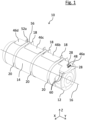
- the tank system 10 shown for a motor vehicle comprises a tank 12 for a fuel with which the motor vehicle can be operated.
- the motor vehicle can be a truck, for example.
- the fuel can be diesel or gasoline, for example, but also liquid gas such as liquefied natural gas, compressed natural gas, liquefied or gaseous hydrogen.
- the tank 12 has a cylindrical casing 14 with a center axis 16 extending in the axial direction Y.
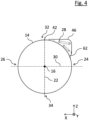
- a vertical centre plane 22 of the tank 12 which contains the centre axis 16 and is in the position of use of the tank 12 (i.e. in a state mounted on the vehicle), defines a vehicle-side side 24 of the tank 12 and a side 26 of the tank 12 facing away from the motor vehicle (cf. Figures 3 and 4 , each showing a cross-sectional view of the tank system in the area of a clamping band 20 and in the area of a housing 46).
- a horizontal center plane 30 of the tank 12 in the position of use of the tank 12, which contains the center axis 16, defines a tank top 32 and a tank bottom 34.
- the axial direction Y is a direction that runs parallel to the center axis 16 of the casing 14 (cf.
- the vertical direction Z is a direction that runs perpendicular to the axial direction Y and in a direction from the tank bottom 34 to the tank top 32.
- the horizontal direction X is a direction that runs perpendicular to the axial direction Y and the vertical direction Z, ie the horizontal direction runs in a direction from the vehicle-side side 24 of the tank 12 to the side 26 of the tank 12 facing away from the motor vehicle.
- the tank system 10 shown further comprises three holding devices 18 or support brackets which can be mounted on a frame or chassis (not shown) of a motor vehicle.
- each holding device 18 comprises a web section 36 and a mounting section 38.
- the web section 36 is in the shown position of use of the Tanks 12 in the area of the tank top 32 at least partially does not rest on the casing 14.
- the web section 36 protrudes from the casing 14 on the tank top 32, with a distance between the web section 36 and the casing 14 increasing in the vertical direction Z.
- the mounting section 38 is adapted to the curvature or radius of the casing 14 and rests at least partially on the casing 14 in the area of the tank bottom 34. Deviating from the embodiment shown, the section 38 can also protrude further under the tank 12 in order to bear more of its weight.
- the tank 12 is fixed to the respective holding devices 18 by means of three tensioning straps 20, wherein a first end 52a of each tensioning strap 20 is fixed to an upper end 40 of the web section 36 of the holding device 18 and a second end 52b of each tensioning strap 20 is fixed to the mounting section 38 of the holding device 18 (cf. Fig.3 ).
- the first ends 52a of the tensioning straps 20 are fixed to webs 56 of the web sections 36 and the second ends 52b of the tensioning straps 20 are fixed to webs 58 of the mounting sections 38.
- the ends 52a, 52b of the tensioning straps 20 can also be fixed in another way.
- either none, one or both ends 52a, 52b of the tensioning straps 20 can be fixed to the holding devices 18 in a removable or detachable manner.
- the holding devices 18, in particular their web sections 36, are preferably designed to be sufficiently rigid so that they do not bend or distort significantly when the tensioning straps 20 are tightened.
- the tank system 10 comprises one, two or more than two fittings 28 connected to the tank 12.
- the fitting 28 extends at least in sections in the axial direction Y or has an extension component in the axial direction Y.
- a not insignificant section of the casing 14 in the axial direction Y is occupied by components of the fitting 28.
- the fittings 28 are arranged on the vehicle side 24 and on the tank top 32 of the tank 12. This arrangement provides the tank 12 with extensive protection for the fittings 28.
- the fittings 28 are guided under the tensioning band 20 without the tensioning band 20 resting against the fittings 28.
- the fittings 28 are arranged in a gusset 44 which is enclosed between the casing 14, the tensioning band 20 and the web section 36 of the holding device 18. Consequently, the tensioning band 20 fulfills two functions, namely securing the tank 12 to the corresponding holding device 18 and protecting a section of the fitting 28 underneath.
- the tank system 10 also comprises a housing 46 which at least partially covers the fitting 28, i.e. the housing 46, like the fitting 28, is arranged on the vehicle-side side 24 of the tank 12 on the tank top 32 (cf. Fig.4 ).
- the clamping band 20 is arranged in the axial direction Y next to the housing 46, ie the clamping band 20 is not guided over the housing 46.
- the clamping band 20 is guided along the circumferential direction of the casing 14 to fix the tank 12 and rests against the casing 14 at least on the side 26 of the tank 12 facing away from the vehicle (cf. Fig.3 ).
- the housing 46 can be welded to the casing 14.
- the housing 46 is fixed to the casing 14 in a detachable and/or foldable manner.
- the fitting 28 can be accessible through at least one opening 48 of the housing 46 (cf. Fig.1 ), whereby the opening 48 can be closed with a lid (not shown).
- the housing 46 comprises four housing segments 46a-d arranged next to one another along the axial direction Y, wherein the housing segments 46a-d (except for a small part of the segment 46a) are arranged on the vehicle-side side 24 of the tank 12 on the tank top 32 and at least partially cover the fittings 28.
- a tensioning band 20 is provided between each of the housing segments 46a-d, which also serves as a cover for the fittings 28.
- the tensioning bands 20 are guided between the housing segments 46a-d in the circumferential direction over at least half of the casing 14 that faces away from the vehicle.
- the housing segment 46a which is arranged at a front end of the tank 12, has openings 48 for connections of the fittings 28.
- the housing segment 46a is screwed to the casing 14 by means of two screws 60 on the tank top 32.
- the housing segments 46a-d on the vehicle side 24 are also fixed to the casing 14 by means of two locking elements 62 each.
- each housing segment 46a-d can be removed individually without having to loosen a clamping band 20.
- the housing segments 46a-d can also be releasably fixed to the casing 14 by means of clamping or plug connections (not shown).
- housing segments 46a-d can be fixed to the casing 14 by means of hinges that can be opened and closed.
- hinges can be provided in addition to or as an alternative to the clamping, locking or plug-in connections.
- the housing segments 46a-d can be welded to the casing 14.
- clamping straps 20 or holding devices 18 is not limited to three. For example, four or more or only two clamping straps 20 and holding devices 18 can be provided.
- the number of housing segments can also vary accordingly. For example, an embodiment not shown is possible in which the tank 12 is fixed to respective holding devices 18 by means of two clamping straps 20.
- a housing 46 can be arranged between the two clamping straps 20, or it can be Housing segments can be arranged between and/or next to the clamping bands 20.
- the fittings 28 are arranged predominantly on the vehicle-side side 24 of the tank 12 on the tank top 32.
- embodiments not shown are also possible in which the fittings 28 are arranged predominantly on the vehicle-side side 24 of the tank 12 on the tank bottom 34. Accordingly, in such a configuration, the mounting section 38 in the area of the tank top 32 at least partially rests on the casing 14, the web section 36 in the area of the tank bottom 34 at least partially does not rest on the casing 14 and the housing 46 is arranged on the vehicle-side side 24 of the tank 12 on the tank bottom 34.
- fittings 28 are arranged on the tank top 32 and the tank bottom 34.
- the holding devices 18 do not have any mounting sections 38.
- the holding devices 18 here have two web sections 36, each of which at least partially does not rest against the casing 14, and housings 46 are provided accordingly on the tank top 32 and the tank bottom 34.
- the tensioning band 20 can have a coating, which preferably comprises an elastic material, at least in sections.
- the coating can be a rubber coating.
- the tensioning band 20 can have the coating along its longitudinal direction and/or circumferential direction completely or in sections.
- the coating can only be provided in a section in which the tensioning band 20 rests against the casing 14 and/or in a section close to the housing 46.
- the coating can only be arranged on one or both edges of the tensioning band 20.
- the coating can also be extend along the entire length of the tensioning band 20 and/or completely enclose the tensioning band 20 in the circumferential direction.
- the coating serves in particular to protect the tensioning band 20 and adjacent components, such as the fitting 28 and the housing 46, and to reduce noise emissions caused by vibrations and friction of the tensioning band 20.
- the tensioning band 20 has a coating 50 in the form of a rubber or elastomer sheath, which encloses the tensioning band 20 essentially completely in the circumferential direction and which extends essentially along the entire length of the band 20.
- the sheath protects the surface of the tensioning band 20 largely or even completely from environmental influences.
- the vertical sections 54 of the housing segments 46c, 46d protrude from the housing 46 to the casing 14 and thus form side walls that protect the interior of the segments 46c, 46d from environmental influences.
- the sections 54 can have openings and/or recesses for the fittings 28. They can be formed in one piece with the rest of the segments 46c, 46d (in Fig. 5A right section 54) or separate components that are attached (eg welded) to the rest of the segments 46c, 46d (in Fig. 5A left section 54).
- Fig. 5B The embodiment shown differs from that in Fig. 5A shown essentially in that the coating 50 does not completely enclose the clamping band 20 in the circumferential direction, ie the rubber coating is designed here in the form of two sealing lips 57 arranged on the edges of the clamping band 20.
- the sealing lips 57 can be replaced quickly and easily when worn, without having to replace the entire clamping band 20.
- sealing lips 57 can also be (solid) plastic components.
- FIG. 6A The embodiment shown differs from the ones shown in the Figures 5A and 5B shown essentially in that the housing 46 does not have a vertical section 54 but rather an edge facing the tensioning band 20 with a coating in the form of an edge protector 59.
- the edges of adjacent housing segments 46c, 46d each have an edge protector 59.
- the edge protector 59 is preferably made of elastic material (plastic components are also conceivable) and in the variant shown is designed as a type of sealing element or sealing lip which is placed on the edges of the housing segments 46c, 46d and which rests on a surface section of the tensioning band 20.
- a rubber coating in the form of two sealing lips 57 arranged on the edges of the tensioning band 20 and the edges of the adjacent housing segments 46c, 46d also each have a sealing lip 59.
- the sealing lips 57 of the tensioning band 20 each lie on the adjacent sealing lips 59 of the edges of the housing segments 46c, 46d, so that here too the gusset 44 is sealed and the tensioning band 20 and adjacent components are protected.
- Fig. 6C In the embodiment shown, only the edges of the clamping band 20 have sealing lips 57, which are located at the edges of the housing segments 46c, 46d (see also Fig. 5B ). Sealing of the gusset 44 is also ensured and the tensioning band 20 and surrounding components are protected.
Landscapes
- Engineering & Computer Science (AREA)
- Life Sciences & Earth Sciences (AREA)
- Sustainable Development (AREA)
- Sustainable Energy (AREA)
- Chemical & Material Sciences (AREA)
- Combustion & Propulsion (AREA)
- Transportation (AREA)
- Mechanical Engineering (AREA)
- Cooling, Air Intake And Gas Exhaust, And Fuel Tank Arrangements In Propulsion Units (AREA)
Abstract
Description
- Die Erfindung betrifft ein Tanksystem für ein Kraftfahrzeug, das mit einem Betriebsstoff, insbesondere mit einem gasförmigen oder einem flüssigen Medium, vorzugsweise Flüssiggas, betreibbar ist.
- Tanksysteme dienen insbesondere der Lagerung und Bereitstellung von Betriebsmitteln eines Kraftfahrzeugs. Dazu gehören herkömmliche Kraftstoffe wie zum Beispiel Diesel- oder Benzinbetriebsstoff, aber auch Flüssiggas wie zum Beispiel verflüssigter Wasserstoff (LH2) oder verflüssigtes Erdgas (LNG). Solche Tanksysteme umfassen zum Beispiel einen Tank für den Betriebsstoff mit einem zylindrischen Mantel, der eine sich in axialer Richtung erstreckende Mittenachse aufweist, und zumindest eine an dem Kraftfahrzeug montierbare Halteeinrichtung oder Tragekonsole, an der der Tank mittels zumindest eines Spannbandes fixiert ist. Die Tragekonsolen werden beispielsweise seitlich am Fahrgestell oder Rahmen eines Lastkraftwagens angebracht.
- Bei üblichen Tanksystemen zur Lagerung von Dieselbetriebsstoff sind beispielsweise zwei L-förmige Stegbleche an den Rahmen eines Fahrzeugs angeschraubt und ein Betriebsstofftank an den Stegblechen mittels Spanngurten oder Spannbändern festgezurrt. Die Spannbänder werden dabei über die Oberfläche des Tankmantels geführt.
- Handelst es sich jedoch um Flüssiggastanks, ist eine Montage mit Hilfe von Spannbändern nicht ohne weiteres möglich, da ein Teil der Mantelfläche des Tanks von an den Tank angeschlossenen Armaturen belegt bzw. bedeckt ist. Unter dem Begriff "Armatur" sind beispielsweise Einrichtungen zum Betanken, Entleeren und/oder Entlüften des Tanks zu verstehen, z.B. Stutzen, Flansche, Leitungen, Wärmeübertrager, Ventile o.ä.. Insbesondere kann es vorkommen, dass sich Teile der Armaturen in Längsrichtung über weite Abschnitte des Tankmantels erstrecken, sodass die Spannbänder an nur wenigen Stellen zwischen oder neben den Armaturen auf dem Mantel positioniert werden können. Da im montierten Zustand des Tanks die Enden der Spannbänder an den Tragekonsolen fixiert sind, ist folglich auch die Montageposition der Tragekonsolen an dem Fahrzeugrahmen erheblich eingeschränkt.
- Zudem sind die Armaturen bei Betrieb des Kraftfahrzeugs Umwelteinflüssen wie Stößen oder Korrosion ausgesetzt. Werden die Armaturen jedoch durch ein Blech oder Ähnliches geschützt, das zwischen den Spannbändern und den Armaturen angeordnet ist, sind die Armaturen nur schwer zugänglich, was den Betrieb und die Wartung des Tanks bzw. der Armaturen erschwert. Eine solche Lösung ist in der Druckschrift
EP 3 121 051 B1 beschrieben. Sie sieht ein Gehäuse vor, das an dem Tankmantel angebracht ist und das einen Zwickel bildet, durch das die Armaturen geführt sind. Die Spannbänder sind über das Gehäuse geführt. - Es ist eine Aufgabe der Erfindung, ein verbessertes Tanksystem für ein Kraftfahrzeug bereitzustellen, das die vorgenannten Probleme ausräumt.
- Die vorgenannte Aufgabe wird durch ein Tanksystem für ein Kraftfahrzeug gemäß dem Anspruch 1 und insbesondere dadurch gelöst, dass zumindest eine an den Tank angeschlossene Armatur zumindest teilweise auf einer fahrzeugseitigen Seite des Tanks angeordnet und unter dem Spannband hindurchgeführt ist, wobei eine in Gebrauchslage des Tanks vertikale Mittenebene des Tanks, die die Mittenachse enthält, die fahrzeugseitige Seite des Tanks und eine dem Kraftfahrzeug abgewandte Seite des Tanks definiert.
- Die fahrzeugseitige Anordnung der Armatur ermöglicht einen besseren Schutz der Armatur vor Umwelteinflüssen, da beispielsweise Stöße oder Spritzwasser von dem Tank abgefangen werden. Einen zusätzlichen Schutz bietet der Teil des Spannbandes, unter dem ein Abschnitt der Armatur hindurchgeführt ist. Eine solche Anordnung der Armatur unter dem Spannband bewirkt zudem, dass das Spannband an einer beliebigen Position über den Tankmantel geführt werden kann, was wiederum die Montage des Tanks an dem Fahrzeug vereinfacht.
- Für eine erleichterte Zugänglichkeit kann die Armatur auf der Tankoberseite angeordnet sein, wobei eine in Gebrauchslage des Tanks horizontale Mittenebene des Tanks, die die Mittenachse enthält, die Tankoberseite und eine Tankunterseite definiert.
- Die Halteeinrichtung kann ferner einen Stegabschnitt aufweisen, der zumindest abschnittsweise nicht an dem Mantel anliegt. Bevorzugt liegt der Stegabschnitt in Gebrauchslage nicht im Bereich der Tankoberseite an dem Mantel an.
- Zudem kann die Armatur zumindest teilweise in einem Zwickel angeordnet sein, der zwischen dem Mantel, dem Spannband und dem Stegabschnitt der Halteeinrichtung eingeschlossen ist. Dies ermöglicht eine Führung des Spannbandes über die Armatur, ohne dass dabei das Spannband und die Armatur zusammenwirken, d.h. die Armatur wird im montierten Zustand des Tanks nicht durch das Spannband belastet.
- Die Halteeinrichtung kann zudem einen Montageabschnitt aufweisen, der an die Krümmung des Mantels angepasst ist und zumindest teilweise an dem Mantel anliegt. Insbesondere kann der Montageabschnitt in Gebrauchslage im Bereich der Tankunterseite zumindest teilweise an dem Mantel anliegen. Dies ermöglicht eine noch stabilere Sicherung des Tanks an der Halteeinrichtung. Gleichzeitig wird das Spannband weniger stark beansprucht, da ein Teil des Gewichts des Tanks von dem Montageabschnitt aufgenommen wird.
- Für einen noch besseren Schutz der Armatur kann das Tanksystem des Weiteren ein Gehäuse umfassen, das die Armatur zumindest teilweise abdeckt, wobei das Spannband in axialer Richtung neben dem Gehäuse angeordnet ist. Insbesondere können zumindest zwei Spannbänder vorgesehen sein, zwischen denen das Gehäuse angeordnet ist. Zum einen verhindert diese Anordnung des Spannbandes bzw. der Spannbänder neben dem Gehäuse eine Krafteinwirkung des Spannbandes auf das Gehäuse bzw. eine Quetschung des Gehäuses durch das Spannband. In anderen Worten, die Kraftübertragung erfolgt über die ohnehin stabil auszuführende Manteloberfläche und nicht über ein Gehäuse oder Schutzblech, bei dem die Gefahr besteht, dass es durch das Spannband verbogen wird, wenn es nicht hinreichend massiv ausgestaltet ist. Ein solches Gehäuse ist jedenfalls schwerer (was nachteilig ist) als ein Gehäuse, das nicht durch ein oder mehrere Spannbänder belastet wird. Letzteres kann ein vergleichsweise einfaches Blechbauteil sein. Dadurch, dass das Spannband nicht über das Gehäuse geführt ist, kann das Gehäuse zum anderen einfach demontiert werden, ohne dabei das Spannband lösen zu müssen, d.h. die Armatur ist einfach und schnell auch im montierten Zustand des Tanks für Wartungsarbeiten oder Ähnliches zugänglich.
- Für eine noch bessere Wartungsfreundlichkeit kann das Gehäuse segmentiert sein, d.h. das Gehäuse kann zwei oder mehr, insbesondere vier, entlang der axialen Richtung nebeneinander angeordnete Gehäusesegmente umfassen, wobei zwischen den Gehäusesegmenten jeweils ein Spannband vorgesehen ist. Folglich muss für eine Wartung der Armatur nicht das gesamte Gehäuse entfernt werden, sondern es können je nach Bedarf nur einzelne Gehäusesegmente entnommen werden.
- Zusätzlich oder alternativ kann das Gehäuse an dem Mantel lösbar und/oder auf- und zuklappbar fixiert sein, was die Benutzerfreundlichkeit weiter erhöht. Insbesondere kann das Gehäuse an dem Mantel mittels zumindest einer Schraub-, Rast-, Steck- und/oder Klemmverbindung und/oder einem Scharnier fixiert sein.
- Die Armatur kann durch zumindest eine Öffnung des Gehäuses zumindest abschnittsweise zugänglich sein, was insbesondere das Betreiben und Anschließen der Armatur erleichtert. Die Öffnung kann mit einem Deckel verschließbar sein, um Anschlüsse der Armatur vor Umwelteinflüssen zu schützen.
- Des Weiteren kann das Spannband zumindest abschnittsweise eine Beschichtung aufweisen. Die Beschichtung kann eine Gummierung umfassen, die an zumindest einer Kante des Spannbandes vorgesehen ist und/oder das Spannband in Umfangsrichtung umschließt. Die Gummierung kann auch an beiden Kanten des Spannbandes vorgesehen sein. Die Beschichtung dient zur Reduzierung von Schallemissionen und zum Schutz des Spannbandes vor Korrosion und mechanischer Beschädigung.
- Die Beschichtung kann ferner in einem dem Gehäuse benachbarten und/oder zugewandten Bereich angeordnet sein. Insbesondere kann die Beschichtung derart ausgestaltet sein, dass sie zwischen dem Spannband und einem Abschnitt des Gehäuses wirkt und eine Bewegung des Spannbandes in vertikaler Richtung limitiert, sodass das Spannband bei Betrieb des Fahrzeugs nicht gegen das Gehäuse reibt oder schwingt.
- Zum Schutz des Gehäuses kann das Gehäuse einen Kantenschutz aufweisen. Insbesondere kann ein Dichtelement an zumindest einer dem Spannband zugewandten Kante des Gehäuses vorgesehen sein. Das Gehäuse kann auch (abschnittsweise) beschichtet (z. B. gummiert) sein, insbesondere in einem dem Spannband benachbarten und/oder zugewandten Bereich.
- Ferner kann das Gehäuse benachbart zu dem Spannband einen vertikalen Abschnitt aufweisen, der von dem Gehäuse zu dem Mantel hinragt, sodass die Armatur nicht nur in vertikaler Richtung, sondern auch in axialer Richtung geschützt ist. Ein Eindringen von Fremdkörpern in den von dem Gehäuse begrenzten Raum wird so weitgehend verhindert.
- Für eine sichere und stabile Montage des Tanks kann ein erstes Ende des Spannbands an dem Stegabschnitt fixiert sein und ein zweites Ende des Spannbands an dem Montageabschnitt fixiert sein. Insbesondere kann das erste Ende des Spannbandes an einem oberen Ende des Stegabschnitts fixiert sein, um eine Quetschung der Armatur durch das Spannband auszuschließen.
- Nachfolgend wird die Erfindung beispielhaft anhand vorteilhafter Ausführungsformen unter Bezugnahme auf die beigefügten Figuren beschrieben. Es zeigen, jeweils schematisch:
- Fig. 1, 2
- perspektivische Ansichten einer Ausführungsform eines Tanksystems,
- Fig. 3
- eine Querschnittsansicht des Tanksystems von
Fig. 1 und2 in einem Bereich des Spannbandes, - Fig. 4
- eine Querschnittsansicht des Tanksystems von
Fig. 1 und2 in einem Bereich des Gehäuses, und - Fig. 5A-6B
- perspektivische Detailansichten eines Tanksystems gemäß verschiedener Ausführungsformen.
- Das in den
Figuren 1 und2 gezeigte Tanksystem 10 für ein Kraftfahrzeug umfasst einen Tank 12 für einen Betriebsstoff, mit dem das Kraftfahrzeug betreibbar ist. Das Kraftfahrzeug kann beispielsweise ein Lastkraftwagen sein. Der Betriebsstoff kann beispielsweise Diesel oder Benzin sein, aber auch Flüssiggas wie zum Beispiel verflüssigtes Erdgas, komprimiertes Erdgas, verflüssigter oder gasförmiger Wasserstoff. Der Tank 12 weist einen zylindrischen Mantel 14 mit einer sich in axialer Richtung Y erstreckenden Mittenachse 16 auf. - Im Folgenden definiert eine in Gebrauchslage des Tanks 12 (also in einem an den Fahrzeug montierten Zustand) vertikale Mittenebene 22 des Tanks 12, die die Mittenachse 16 enthält, eine fahrzeugseitige Seite 24 des Tanks 12 und eine dem Kraftfahrzeug abgewandte Seite 26 des Tanks 12 (vgl.
Figuren 3 und4 , die jeweils eine Querschnittsansicht des Tanksystems im Bereich eines Spannbandes 20 und im Bereich eines Gehäuses 46 zeigen). Eine in Gebrauchslage des Tanks 12 horizontale Mittenebene 30 des Tanks 12, die die Mittenachse 16 enthält, definiert hingegen eine Tankoberseite 32 und eine Tankunterseite 34. Als axiale Richtung Y wird eine Richtung bezeichnet, die parallel zur Mittenachse 16 des Mantels 14 verläuft (vgl. Koordinatensystem inFig. 1 ). Als vertikale Richtung Z wird eine Richtung bezeichnet, die senkrecht zur axialen Richtung Y und in einer Richtung von der Tankunterseite 34 zu der Tankoberseite 32 verläuft. Als horizontale Richtung X wird eine Richtung bezeichnet, die senkrecht zu der axialen Richtung Y und der vertikalen Richtung Z verläuft, d.h. die horizontale Richtung verläuft in einer Richtung von der fahrzeugseitigen Seite 24 des Tanks 12 zu der dem Kraftfahrzeug abgewandten Seite 26 des Tanks 12. - Das gezeigte Tanksystem 10 umfasst des Weiteren drei Halteeinrichtungen 18 oder Tragekonsolen, die an einem nicht gezeigten Rahmen oder Chassis eines Kraftfahrzeugs montierbar sind. Wie insbesondere in den
Figuren 2 und3 gezeigt ist, umfasst jede Halteeinrichtung 18 einen Stegabschnitt 36 und einen Montageabschnitt 38. Der Stegabschnitt 36 liegt in der gezeigten Gebrauchslage des Tanks 12 im Bereich der Tankoberseite 32 zumindest teilweise nicht an dem Mantel 14 an. In anderen Worten, der Stegabschnitt 36 steht auf der Tankoberseite 32 von dem Mantel 14 ab, wobei ein Abstand zwischen dem Stegabschnitt 36 und dem Mantel 14 in vertikaler Richtung Z zunimmt. Der Montageabschnitt 38 ist an die Krümmung bzw. den Radius des Mantels 14 angepasst und liegt zumindest teilweise im Bereich der Tankunterseite 34 an dem Mantel 14 an. Abweichend von der gezeigten Ausführungsform kann der Abschnitt 38 auch weiter unter den Tank 12 ragen, um mehr von dessen Gewicht zu tragen. - Der Tank 12 ist mit Hilfe von drei Spannbändern 20 an den jeweiligen Halteeinrichtungen 18 fixiert, wobei ein erstes Ende 52a eines jeden Spannbandes 20 an einem oberen Ende 40 des Stegabschnitts 36 der Halteeinrichtung 18 und ein zweites Ende 52b eines jeden Spannbandes 20 an dem Montageabschnitt 38 der Halteeinrichtung 18 fixiert ist (vgl.
Fig. 3 ). Insbesondere sind die ersten Enden 52a der Spannbänder 20 an Stegen 56 der Stegabschnitte 36 fixiert und die zweiten Enden 52b der Spannbänder 20 an Stegen 58 der Montageabschnitte 38 fixiert. Die Fixierung der Enden 52a, 52b der Spannbänder 20 kann jedoch auch anderweitig erfolgen. Zudem kann entweder keines, eines oder beide Enden 52a, 52b der Spannbänder 20 abnehmbar oder lösbar an den Halteeinrichtungen 18 fixiert sein. Die Halteeinrichtungen 18, insbesondere deren Stegabschnitte 36, sind bevorzugt hinreichend steif ausgebildet, sodass sie sich nicht wesentlich verbiegen oder verziehen, wenn die Spannbänder 20 festgezurrt werden. - Darüber hinaus umfasst das Tanksystem 10 eine, zwei oder mehr als zwei an dem Tank 12 angeschlossene Armaturen 28. In den
Figuren 1 und2 sind nur die Anschlussbereiche der Armaturen 28 deutlich erkennbar. Die Armatur 28 erstreckt sich jedoch zumindest abschnittsweise in axialer Richtung Y bzw. weist eine Erstreckungskomponente in axialer Richtung Y auf. Insbesondere ist es möglich, dass ein nicht unwesentlicher Abschnitt des Mantels 14 in axialer Richtung Y durch Komponenten der Armatur 28 belegt ist. - Wie insbesondere in
Fig. 3 zu sehen ist, sind die Armaturen 28 auf der fahrzeugseitigen Seite 24 und auf der Tankoberseite 32 des Tanks 12 angeordnet. Durch diese Anordnung schützt der Tank 12 die Armaturen 28 weitgehend. Die Armaturen 28 sind unter dem Spannband 20 hindurchgeführt, ohne dass dabei das Spannband 20 an den Armaturen 28 anliegt. Die Armaturen 28 sind in einem Zwickel 44 angeordnet, der zwischen dem Mantel 14, dem Spannband 20 und dem Stegabschnitt 36 der Halteeinrichtung 18 eingeschlossen ist. Folglich erfüllt das Spannband 20 zwei Funktionen, nämlich die Sicherung des Tanks 12 an der entsprechenden Halteeinrichtung 18 und den Schutz eines Abschnitts der darunterliegenden Armatur 28. - Das Tanksystem 10 umfasst zudem ein Gehäuse 46, das die Armatur 28 zumindest teilweise abdeckt, d.h. das Gehäuse 46 ist, ebenso wie die Armatur 28, auf der fahrzeugseitigen Seite 24 des Tanks 12 auf der Tankoberseite 32 angeordnet (vgl.
Fig. 4 ). Das Spannband 20 ist in axialer Richtung Y neben dem Gehäuse 46 angeordnet, d.h. das Spannband 20 ist nicht über das Gehäuse 46 geführt. Das Spannband 20 ist zu Fixierung des Tanks 12 entlang der Umfangsrichtung des Mantels 14 geführt und liegt an dem Mantel 14 zumindest auf der dem Fahrzeug abgewandten Seite 26 des Tanks 12 an (vgl.Fig. 3 ). Das Gehäuse 46 kann an den Mantel 14 geschweißt sein. Bevorzugt ist das Gehäuse 46 aber lösbar und/oder auf- und zuklappbar an dem Mantel 14 fixiert. Die Armatur 28 kann durch zumindest eine Öffnung 48 des Gehäuses 46 zugänglich sein (vgl.Fig. 1 ), wobei die Öffnung 48 mit einem Deckel verschließbar sein kann (nicht gezeigt). - In der in den
Figuren 1 und2 gezeigten Ausführungsform umfasst das Gehäuse 46 vier entlang der axialen Richtung Y nebeneinander angeordnete Gehäusesegmente 46a-d, wobei die Gehäusesegmente 46a-d (bis auf einen kleinen Teil des Segments 46a) auf der fahrzeugseitigen Seite 24 des Tanks 12 auf der Tankoberseite 32 angeordnet sind und die Armaturen 28 zumindest teilweise abdecken. - Zwischen den Gehäusesegmenten 46a-d ist jeweils ein Spannband 20 vorgesehen, das ebenfalls als Abdeckung für die Armaturen 28 dient. Die Spannbänder 20 sind dabei zwischen den Gehäusesegmenten 46a-d in Umfangsrichtung über zumindest die Hälfte des Mantels 14 geführt, die dem Fahrzeug abgewandt ist. Das Gehäusesegment 46a, das an einem vorderen Ende des Tanks 12 angeordnet ist, weist Öffnungen 48 für Anschlüsse der Armaturen 28 auf.
- Wie in
Fig. 1 zu sehen ist, ist das Gehäusesegment 46a mittels zweier Schrauben 60 auf der Tankoberseite 32 an dem Mantel 14 festgeschraubt. Wie inFig. 2 gezeigt ist, sind die Gehäusesegmente 46a-d auf der fahrzeugseitigen Seite 24 zudem mittels jeweils zwei Rastelementen 62 an dem Mantel 14 fixiert. Dadurch kann jedes Gehäusesegment 46a-d einzeln entnommen werden, ohne dafür ein Spannband 20 lösen zu müssen. Zusätzlich oder alternativ hierzu können die Gehäusesegmente 46a-d aber auch mittels nicht gezeigter Klemm- oder Steckverbindungen lösbar an dem Mantel 14 fixiert sein. - Zudem ist es möglich, dass die Gehäusesegmente 46a-d mittels Scharnieren auf- und zuklappbar an dem Mantel 14 fixiert sind. Beispielsweise können zusätzlich oder alternativ zu den Klemm-, Rast- oder Steckverbindungen Scharniere vorgesehen sein. Im Gegensatz dazu ist es aber auch denkbar, dass die Gehäusesegmente 46a-d an den Mantel 14 geschweißt sind.
- Es versteht sich, dass die Anzahl an Spannbändern 20 bzw. Halteeinrichtungen 18 nicht auf drei beschränkt ist. Beispielsweise können auch vier oder mehr oder nur zwei Spannbänder 20 und Halteeinrichtungen 18 vorgesehen sein. Entsprechend kann auch die Anzahl an Gehäusesegmenten variieren. Beispielsweise ist eine nicht gezeigte Ausführungsform möglich, bei der der Tank 12 mittels zwei Spannbändern 20 an jeweiligen Halteeinrichtungen 18 fixiert ist. Dabei kann ein Gehäuse 46 zwischen den beiden Spannbändern 20 angeordnet sein, oder es können Gehäusesegmente zwischen und/oder neben den Spannbändern 20 angeordnet sein.
- In der gezeigten Ausführungsform sind die Armaturen 28 überwiegend auf der fahrzeugseitigen Seite 24 des Tanks 12 auf der Tankoberseite 32 angeordnet. Es sind jedoch auch nicht gezeigte Ausführungsformen möglich, bei der die Armaturen 28 überwiegend auf der fahrzeugseitigen Seite 24 des Tanks 12 auf der Tankunterseite 34 angeordnet sind. Entsprechend liegt bei einer solchen Konfiguration der Montageabschnitt 38 im Bereich der Tankoberseite 32 zumindest teilweise an dem Mantel 14 an, der Stegabschnitt 36 liegt im Bereich der Tankunterseite 34 zumindest teilweise nicht an dem Mantel 14 an und das Gehäuse 46 ist auf der fahrzeugseitigen Seite 24 des Tanks 12 auf der Tankunterseite 34 angeordnet.
- Ferner ist eine nicht gezeigte Ausführungsform möglich, bei der Armaturen 28 auf der Tankoberseite 32 und der Tankunterseite 34 angeordnet sind. In diesem Fall weisen die Halteeinrichtungen 18 keine Montageabschnitte 38 auf. Insbesondere weisen hier die Halteeinrichtungen 18 zwei Stegabschnitte 36 auf, die jeweils zumindest teilweise nicht an dem Mantel 14 anliegen, und Gehäuse 46 sind entsprechend auf der Tankoberseite 32 und der Tankunterseite 34 vorgesehen.
- Um unter anderem die Haltbarkeit des Spannbandes 20 zu verbessern, kann das Spannband 20 zumindest abschnittsweise eine Beschichtung aufweisen, die bevorzugt ein elastisches Material umfasst. Die Beschichtung kann eine Gummierung sein. Das Spannband 20 kann die Beschichtung entlang seiner Längsrichtung und/oder Umfangsrichtung vollständig oder abschnittsweise aufweisen. Beispielsweise kann die Beschichtung nur in einem Abschnitt, in dem das Spannband 20 an dem Mantel 14 anliegt, und/oder in einem Abschnitt nahe dem Gehäuse 46 vorgesehen sein. Zudem kann die Beschichtung nur auf einer oder beiden Kanten des Spannbandes 20 angeordnet sein. Die Beschichtung kann sich jedoch auch entlang der gesamten Länge des Spannbandes 20 erstrecken und/oder das Spannband 20 in Umfangsrichtung vollständig umschließen. Die Beschichtung dient insbesondere zum Schutz des Spannbandes 20 und benachbarter Bauteile, wie die Armatur 28 und das Gehäuse 46, sowie zur Reduzierung von durch Schwingungen und Reibungen des Spannbandes 20 hervorgerufenen Schallemissionen.
- In der in
Fig. 5A gezeigten Ausführungsform weist das Spannband 20 eine Beschichtung 50 in Form einer Gummi- oder Elastomerummantelung auf, die das Spannband 20 im Wesentlichen vollständig in Umfangsrichtung umschließt und die sich im Wesentlichen entlang der gesamten Länge des Bands 20 erstreckt. Durch die Ummantelung ist die Oberfläche des Spannbandes 20 weitgehend oder sogar vollständig vor Umwelteinflüssen geschützt. - Es besteht jeweils ein (geringfügiger) Abstand zwischen der Beschichtung 50 und einem vertikalen Abschnitten 54 eines benachbarten Gehäusesegments 46c, 46d. Die vertikalen Abschnitte 54 der Gehäusesegmente 46c, 46d ragen von dem Gehäuse 46 zu dem Mantel 14 hin und bilden somit Seitenwände, die den Innenraum der Segmente 46c, 46d vor Umwelteinflüssen schützen. Die Abschnitte 54 können Öffnungen und/oder Ausnehmungen für die Armaturen 28 aufweisen. Sie können einstückig mit dem Rest der Segmente 46c, 46d ausgebildet sein (in
Fig. 5A rechter Abschnitt 54) oder separate Bauteile sein, die an dem Rest der Segmente 46c, 46d befestigt (z.B. verschweißt) sind (inFig. 5A linker Abschnitt 54). - Die in
Fig. 5B gezeigte Ausführungsform unterscheidet sich von der inFig. 5A gezeigten im Wesentlichen dadurch, dass die Beschichtung 50 das Spannband 20 in Umfangsrichtung nicht vollständig umschließt, d.h. die Gummierung ist hier in Form von zwei an den Kanten des Spannbandes 20 angeordneten Dichtlippen 57 ausgebildet. Die Dichtlippen 57 können bei Verschleiß einfach und schnell ausgetauscht werden, ohne dabei das komplette Spannband 20 wechseln zu müssen. - Anstelle einer Gummierung kann es sich bei den Dichtlippen 57 auch um (feste) Kunststoffbauteile handeln.
- Die in
Fig. 6A gezeigte Ausführungsform unterscheidet sich von den in denFiguren 5A und5B gezeigten im Wesentlichen dadurch, dass das Gehäuse 46 keinen vertikalen Abschnitt 54 sondern eine dem Spannband 20 zugewandte Kante mit einer Beschichtung in Form eines Kantenschutzes 59 aufweist. Insbesondere weisen die Kanten benachbarter Gehäusesegmente 46c, 46d jeweils einen Kantenschutz 59 auf. Der Kantenschutz 59 ist bevorzugt aus elastischem Material gefertigt (Kunststoffbauteile sind ebenfalls denkbar) und ist in der gezeigten Variante als eine Art Dichtelement oder Dichtlippe ausgestaltet, die auf die Kanten der Gehäusesegmente 46c, 46d gesteckt ist und die auf einem Oberflächenabschnitt das Spannbands 20 aufliegt. Dadurch wird eine Bewegung des Spannbandes 20 in vertikaler Richtung Z begrenzt und der Zwickel 44, in dem ein Abschnitt der Armatur 28 angeordnet ist, besser gegen Umwelteinflüsse abgedichtet. Zudem werden Verschließerscheinungen des Spannbandes 20 im Bereich der Gehäusesegmente 46c, 46d, die beispielsweise durch Schwingungen des Spanbandes 20 verursacht werden, minimiert. - Bei der in
Fig. 6B gezeigten Ausführungsform weist das Spannband 20, analog zu der inFig. 5B gezeigten Ausgestaltung, eine Gummierung in Form von zwei an den Kanten des Spannbandes 20 angeordneten Dichtlippen 57 auf und die Kanten der angrenzenden Gehäusesegmente 46c, 46d weisen ebenfalls jeweils eine Dichtlippe 59 auf. Die Dichtlippen 57 des Spannbandes 20 liegen jeweils an den angrenzenden Dichtlippen 59 der Kanten der Gehäusesegmente 46c, 46d an, sodass auch hier der Zwickel 44 abgedichtet wird und das Spannband 20 sowie angrenzende Komponenten geschützt werden. - Im Gegensatz dazu weisen bei der in
Fig. 6C gezeigten Ausführungsform nur die Kanten des Spannbandes 20 Dichtlippen 57 auf, die an den Kanten der Gehäusesegmente 46c, 46d anliegen (siehe auchFig. 5B ). Auch werden eine Abdichtung des Zwickels 44 gewährleistet und das Spannband 20 sowie umliegende Komponenten geschützt. - Es versteht sich, dass Merkmale, die in Bezug auf bestimmte Ausführungsbeispiele der Erfindung beschrieben wurden, mit denen anderer Ausführungsbeispiele kombiniert werden können.
-
- 10
- Tanksystem
- 12
- Tank
- 14
- Mantel
- 16
- Mittenachse
- 18
- Halteeinrichtung
- 20
- Spannband
- 22
- vertikale Mittenebene
- 24
- fahrzeugseitige Seite des Tanks
- 26
- dem Kraftfahrzeug abgewandte Seite des Tanks
- 28
- Armatur
- 30
- horizontale Mittenebene des Tanks
- 32
- Tankoberseite
- 34
- Tankunterseite
- 36
- Stegabschnitt
- 38
- Montageabschnitt
- 40
- oberes Ende des Stegabschnitts
- 42
- obere Mitte des Mantels
- 44
- Zwickel
- 46
- Gehäuse
- 46a-d
- Gehäusesegmente
- 48
- Öffnung des Gehäuses
- 50
- Beschichtung
- 52a, b
- erstes, zweites Ende des Spannbandes
- 54
- vertikaler Abschnitt des Gehäuses
- 56
- Steg des Stegabschnitts
- 58
- Steg des Montageabschnitts
- 57,59
- Dichtlippe
- 60
- Schrauben
- 62
- Rastverbindung
- X
- horizontale Richtung
- Y
- axiale Richtung
- Z
- vertikale Richtung
Claims (15)
- Tanksystem (10) für ein Kraftfahrzeug, das mit einem Betriebsstoff, insbesondere mit einem gasförmigen oder flüssigen Medium, vorzugsweise Flüssiggas, betreibbar ist, umfassendeinen Tank (12) für den Betriebsstoff, der einen zylindrischen Mantel (14) mit einer sich in axialer Richtung (Y) erstreckenden Mittenachse (16) aufweist, undzumindest eine an dem Kraftfahrzeug montierbare Halteeinrichtung (18), an der der Tank (12) mittels zumindest eines Spannbandes (20) fixiert ist,wobei eine in Gebrauchslage des Tanks (12) vertikale Mittenebene (22) des Tanks (12), die die Mittenachse (16) enthält, eine fahrzeugseitige Seite (24) des Tanks (12) und eine dem Kraftfahrzeug abgewandte Seite (26) des Tanks (12) definiert, undzumindest eine an den Tank (12) angeschlossene Armatur (28) zumindest teilweise auf der fahrzeugseitigen Seite (24) des Tanks (12) angeordnet und unter dem Spannband (20) hindurchgeführt ist.
- Tanksystem (10) nach Anspruch 1,wobei eine in Gebrauchslage des Tanks (12) horizontale Mittenebene (30) des Tanks (12), die die Mittenachse (16) enthält, eine Tankoberseite (32) und eine Tankunterseite (34) definiert, undwobei die Armatur (30) auf der Tankoberseite (32) angeordnet ist.
- Tanksystem (10) nach Anspruch 1 oder 2,
wobei die Halteeinrichtung (18) einen Stegabschnitt (36) aufweist, der zumindest abschnittsweise nicht an dem Mantel (14) anliegt, insbesondere in Gebrauchslage nicht im Bereich der Tankoberseite (32). - Tanksystem (10) nach Anspruch 3,
wobei die Armatur (28) zumindest teilweise in einem Zwickel (44) angeordnet ist, der zwischen dem Mantel (14), dem Spannband (20) und dem Stegabschnitt (36) der Halteeinrichtung (18) eingeschlossen ist. - Tanksystem (10) nach zumindest einem der vorherigen Ansprüche,
wobei die Halteeinrichtung (18) einen Montageabschnitt (38) aufweist, der an die Krümmung des Mantels (14) angepasst ist und zumindest teilweise an dem Mantel (14) anliegt, insbesondere in Gebrauchslage im Bereich der Tankunterseite (34). - Tanksystem (10) nach zumindest einem der vorherigen Ansprüche, ferner umfassend
ein Gehäuse (46), das die Armatur (28) zumindest teilweise abdeckt, wobei das Spannband (20) in axialer Richtung (Y) neben dem Gehäuse (46) angeordnet ist, insbesondere wobei zumindest zwei Spannbänder (20) vorgesehen sind, zwischen denen das Gehäuse (46) angeordnet ist. - Tanksystem (10) nach Anspruch 6,
wobei das Gehäuse (46) zwei oder mehr, insbesondere vier, entlang der axialen Richtung (Y) nebeneinander angeordnete Gehäusesegmente (46a-d) umfasst und wobei zwischen den Gehäusesegmenten (46a-d) jeweils ein Spannband (20) vorgesehen ist. - Tanksystem (10) nach Anspruch 6 oder 7,
wobei das Gehäuse (46) an dem Mantel (14) lösbar und/oder auf- und zuklappbar, insbesondere mittels zumindest einer Schraub-, Rast-, Steck- und/oder Klemmverbindung und/oder einem Scharnier, fixiert ist. - Tanksystem (10) nach zumindest einem der Ansprüche 6 bis 8,
wobei die Armatur (28) durch zumindest eine Öffnung (48) des Gehäuses (46) zugänglich ist, insbesondere wobei die Öffnung (48) mit einem Deckel verschließbar ist. - Tanksystem (10) nach zumindest einem der Ansprüche 7-9,
wobei das Spannband (20) nicht über das Gehäuse (46) geführt ist. - Tanksystem (10) nach zumindest einem der vorherigen Ansprüche,
wobei das Spannband (20) zumindest abschnittsweise eine Beschichtung (50) aufweist, insbesondere wobei die Beschichtung (50) eine Gummierung umfasst, die an zumindest einer Kante des Spannbandes (20) vorgesehen ist und/oder das Spannband (20) in Umfangsrichtung umschließt. - Tanksystem (10) nach Anspruch 11,
wobei die Beschichtung (50, 57) in einem dem Gehäuse (46) benachbarten und/oder zugewandten Bereich angeordnet ist. - Tanksystem (10) nach zumindest einem der Ansprüche 7-12,
wobei das Gehäuse (46) einen Kantenschutz (59) aufweist, insbesondere wobei ein Dichtelement an zumindest einer der dem Spannband (20) zugewandten Kante des Gehäuses (46) vorgesehen ist. - Tanksystem (10) nach zumindest einem der Ansprüche 7-12,
wobei das Gehäuse (46) benachbart zu dem Spannband (20) einen vertikalen Abschnitt (54) aufweist, der von dem Gehäuse (46) zu dem Mantel (14) hinragt. - Tanksystem (10) nach einem der vorherigen Ansprüche,
wobei ein erstes Ende (52a) des Spannbands (20) an dem Stegabschnitt (36), insbesondere an einem oberen Ende (40) des Stegabschnitts (36), fixiert ist, und ein zweites Ende (52b) des Spannbands (20) an dem Montageabschnitt (38) fixiert ist.
Applications Claiming Priority (1)
| Application Number | Priority Date | Filing Date | Title |
|---|---|---|---|
| DE102023101159.6A DE102023101159A1 (de) | 2023-01-18 | 2023-01-18 | Tanksystem |
Publications (1)
| Publication Number | Publication Date |
|---|---|
| EP4403395A1 true EP4403395A1 (de) | 2024-07-24 |
Family
ID=89221973
Family Applications (1)
| Application Number | Title | Priority Date | Filing Date |
|---|---|---|---|
| EP23216295.8A Withdrawn EP4403395A1 (de) | 2023-01-18 | 2023-12-13 | Tanksystem |
Country Status (2)
| Country | Link |
|---|---|
| EP (1) | EP4403395A1 (de) |
| DE (1) | DE102023101159A1 (de) |
Citations (4)
| Publication number | Priority date | Publication date | Assignee | Title |
|---|---|---|---|---|
| EP3121051A1 (de) | 2015-07-24 | 2017-01-25 | Salzburger Aluminium Aktiengesellschaft | Tanksystem für ein fahrzeug |
| US10696154B2 (en) * | 2014-05-15 | 2020-06-30 | Quantum Fuel Systems Llc | Cooperating tank and rack superstructure |
| EP3449175B1 (de) * | 2016-04-27 | 2021-03-24 | Scania CV AB | Anordnung für ein flüssiggaskraftstoffsystem für ein fahrzeug |
| US11465493B2 (en) * | 2016-09-30 | 2022-10-11 | Tony Matijevich | Alternative fuel system |
Family Cites Families (2)
| Publication number | Priority date | Publication date | Assignee | Title |
|---|---|---|---|---|
| JP3797092B2 (ja) * | 2000-10-16 | 2006-07-12 | 日産自動車株式会社 | 天然ガス車両の燃料容器保持構造 |
| SE539829C2 (en) * | 2016-04-26 | 2017-12-12 | Scania Cv Ab | LNG truck and method for assembling an LNG truck |
-
2023
- 2023-01-18 DE DE102023101159.6A patent/DE102023101159A1/de active Pending
- 2023-12-13 EP EP23216295.8A patent/EP4403395A1/de not_active Withdrawn
Patent Citations (5)
| Publication number | Priority date | Publication date | Assignee | Title |
|---|---|---|---|---|
| US10696154B2 (en) * | 2014-05-15 | 2020-06-30 | Quantum Fuel Systems Llc | Cooperating tank and rack superstructure |
| EP3121051A1 (de) | 2015-07-24 | 2017-01-25 | Salzburger Aluminium Aktiengesellschaft | Tanksystem für ein fahrzeug |
| EP3121051B1 (de) | 2015-07-24 | 2018-03-14 | Salzburger Aluminium Aktiengesellschaft | Tanksystem für ein fahrzeug |
| EP3449175B1 (de) * | 2016-04-27 | 2021-03-24 | Scania CV AB | Anordnung für ein flüssiggaskraftstoffsystem für ein fahrzeug |
| US11465493B2 (en) * | 2016-09-30 | 2022-10-11 | Tony Matijevich | Alternative fuel system |
Also Published As
| Publication number | Publication date |
|---|---|
| DE102023101159A1 (de) | 2024-07-18 |
Similar Documents
| Publication | Publication Date | Title |
|---|---|---|
| EP2827966B1 (de) | Filterelement und luftfilter | |
| EP3121051B1 (de) | Tanksystem für ein fahrzeug | |
| EP2223727B1 (de) | Filtereinrichtung zur Filtration gasförmiger Fluide | |
| DE2707891B2 (de) | Behälter mit einem Tank | |
| DE102012011612A1 (de) | Speichervorrichtung zum Speichern eines gasförmigen Kraftstoffs unter einem hohen Druck in einem Kraftfahrzeug | |
| DE3537865A1 (de) | Zweikammer-stuetzlager mit hydraulischer daempfung | |
| DE102020134643A1 (de) | Treibstofftank-Modul für gasbetriebenes Fahrzeug | |
| DE202007007060U1 (de) | Gasspeicher | |
| EP4403395A1 (de) | Tanksystem | |
| DE102017207057A1 (de) | Kraftstoffbehälter | |
| DE10010722A1 (de) | Dichtvorrichtung | |
| DE10008140C1 (de) | Schutzrohr für ein Kolben-Zylinderaggregat | |
| DE19935517A1 (de) | Flasche für druckbeaufschlagte Gase | |
| WO2021156144A1 (de) | Behälter mit fixierring für den transport und die lagerung von flüssigkeiten | |
| DE102022106936A1 (de) | Treibstofftank-Modul | |
| DE202008010648U1 (de) | Flüssigkeitsbehälter mit Luftzuführung | |
| DE4032431C1 (en) | Vehicle exhaust suspension unit - incorporates block-shaped rubber holder with bores running parallel to its broad sides | |
| DE4230710C2 (de) | Vorrichtung zur Abdichtung zwischen Ölwanne und Kurbelwellengehäuse einer Brennkraftmaschine | |
| CH461204A (de) | Dom mit Deckel für Druckbehälter, insbesondere rechteckige Heizölbehälter | |
| DE102015200071B4 (de) | Dämpfungsanordnung für eine schwenkbare Klappe oder einen schwenkbaren Deckel eines Kraftfahrzeugs | |
| DE3108850A1 (de) | Verpackungsbehaelter | |
| WO2022017847A1 (de) | Deckel zum verschliessen eines behälters sowie system aus einem behälter und einem deckel | |
| DE10205036A1 (de) | Tragrahmen bzw.-kasten für eine Batterie od.dgl. an Lastkraftwagen | |
| DE102009024728A1 (de) | Luftführungsbauteil mit Resonator | |
| DE10147663A1 (de) | Verstärkungsanordnung bei einer Rohrdurchführung |
Legal Events
| Date | Code | Title | Description |
|---|---|---|---|
| PUAI | Public reference made under article 153(3) epc to a published international application that has entered the european phase |
Free format text: ORIGINAL CODE: 0009012 |
|
| STAA | Information on the status of an ep patent application or granted ep patent |
Free format text: STATUS: THE APPLICATION HAS BEEN PUBLISHED |
|
| AK | Designated contracting states |
Kind code of ref document: A1 Designated state(s): AL AT BE BG CH CY CZ DE DK EE ES FI FR GB GR HR HU IE IS IT LI LT LU LV MC ME MK MT NL NO PL PT RO RS SE SI SK SM TR |
|
| STAA | Information on the status of an ep patent application or granted ep patent |
Free format text: STATUS: REQUEST FOR EXAMINATION WAS MADE |
|
| 17P | Request for examination filed |
Effective date: 20240821 |
|
| RBV | Designated contracting states (corrected) |
Designated state(s): AL AT BE BG CH CY CZ DE DK EE ES FI FR GB GR HR HU IE IS IT LI LT LU LV MC ME MK MT NL NO PL PT RO RS SE SI SK SM TR |
|
| TPAC | Observations filed by third parties |
Free format text: ORIGINAL CODE: EPIDOSNTIPA |
|
| STAA | Information on the status of an ep patent application or granted ep patent |
Free format text: STATUS: EXAMINATION IS IN PROGRESS |
|
| 17Q | First examination report despatched |
Effective date: 20250714 |
|
| STAA | Information on the status of an ep patent application or granted ep patent |
Free format text: STATUS: THE APPLICATION IS DEEMED TO BE WITHDRAWN |
|
| 18D | Application deemed to be withdrawn |
Effective date: 20251115 |