EP4403249A1 - Industrieanlage zur gasbehandlung - Google Patents
Industrieanlage zur gasbehandlung Download PDFInfo
- Publication number
- EP4403249A1 EP4403249A1 EP23305078.0A EP23305078A EP4403249A1 EP 4403249 A1 EP4403249 A1 EP 4403249A1 EP 23305078 A EP23305078 A EP 23305078A EP 4403249 A1 EP4403249 A1 EP 4403249A1
- Authority
- EP
- European Patent Office
- Prior art keywords
- gas
- liquid
- industrial plant
- gas treatment
- treatment unit
- Prior art date
- Legal status (The legal status is an assumption and is not a legal conclusion. Google has not performed a legal analysis and makes no representation as to the accuracy of the status listed.)
- Pending
Links
- 238000011282 treatment Methods 0.000 title claims abstract description 55
- 239000007788 liquid Substances 0.000 claims description 74
- 239000007789 gas Substances 0.000 description 87
- UGFAIRIUMAVXCW-UHFFFAOYSA-N Carbon monoxide Chemical compound [O+]#[C-] UGFAIRIUMAVXCW-UHFFFAOYSA-N 0.000 description 17
- 239000003546 flue gas Substances 0.000 description 17
- 230000004907 flux Effects 0.000 description 12
- 238000012856 packing Methods 0.000 description 9
- 239000002184 metal Substances 0.000 description 6
- 239000004033 plastic Substances 0.000 description 6
- XLYOFNOQVPJJNP-UHFFFAOYSA-N water Substances O XLYOFNOQVPJJNP-UHFFFAOYSA-N 0.000 description 6
- 238000002485 combustion reaction Methods 0.000 description 4
- OKTJSMMVPCPJKN-UHFFFAOYSA-N Carbon Chemical compound [C] OKTJSMMVPCPJKN-UHFFFAOYSA-N 0.000 description 3
- HEMHJVSKTPXQMS-UHFFFAOYSA-M Sodium hydroxide Chemical compound [OH-].[Na+] HEMHJVSKTPXQMS-UHFFFAOYSA-M 0.000 description 3
- 150000001412 amines Chemical class 0.000 description 3
- 229910052799 carbon Inorganic materials 0.000 description 3
- 239000000356 contaminant Substances 0.000 description 3
- 239000000523 sample Substances 0.000 description 3
- QGZKDVFQNNGYKY-UHFFFAOYSA-N Ammonia Chemical compound N QGZKDVFQNNGYKY-UHFFFAOYSA-N 0.000 description 2
- 239000006096 absorbing agent Substances 0.000 description 2
- 239000000919 ceramic Substances 0.000 description 2
- 238000001816 cooling Methods 0.000 description 2
- 238000012423 maintenance Methods 0.000 description 2
- 239000002904 solvent Substances 0.000 description 2
- 239000000126 substance Substances 0.000 description 2
- 239000002253 acid Substances 0.000 description 1
- 150000007513 acids Chemical class 0.000 description 1
- 229910021529 ammonia Inorganic materials 0.000 description 1
- QVGXLLKOCUKJST-UHFFFAOYSA-N atomic oxygen Chemical compound [O] QVGXLLKOCUKJST-UHFFFAOYSA-N 0.000 description 1
- 230000009286 beneficial effect Effects 0.000 description 1
- 150000001875 compounds Chemical class 0.000 description 1
- 239000002737 fuel gas Substances 0.000 description 1
- 238000009434 installation Methods 0.000 description 1
- 239000000463 material Substances 0.000 description 1
- 238000000034 method Methods 0.000 description 1
- 229910052760 oxygen Inorganic materials 0.000 description 1
- 239000001301 oxygen Substances 0.000 description 1
- 238000004064 recycling Methods 0.000 description 1
- 238000005201 scrubbing Methods 0.000 description 1
- 235000011121 sodium hydroxide Nutrition 0.000 description 1
- 229910001220 stainless steel Inorganic materials 0.000 description 1
- 239000010935 stainless steel Substances 0.000 description 1
- 238000011144 upstream manufacturing Methods 0.000 description 1
Images
Classifications
-
- B—PERFORMING OPERATIONS; TRANSPORTING
- B01—PHYSICAL OR CHEMICAL PROCESSES OR APPARATUS IN GENERAL
- B01D—SEPARATION
- B01D53/00—Separation of gases or vapours; Recovering vapours of volatile solvents from gases; Chemical or biological purification of waste gases, e.g. engine exhaust gases, smoke, fumes, flue gases, aerosols
- B01D53/14—Separation of gases or vapours; Recovering vapours of volatile solvents from gases; Chemical or biological purification of waste gases, e.g. engine exhaust gases, smoke, fumes, flue gases, aerosols by absorption
- B01D53/1456—Removing acid components
- B01D53/1475—Removing carbon dioxide
-
- B—PERFORMING OPERATIONS; TRANSPORTING
- B01—PHYSICAL OR CHEMICAL PROCESSES OR APPARATUS IN GENERAL
- B01D—SEPARATION
- B01D53/00—Separation of gases or vapours; Recovering vapours of volatile solvents from gases; Chemical or biological purification of waste gases, e.g. engine exhaust gases, smoke, fumes, flue gases, aerosols
- B01D53/14—Separation of gases or vapours; Recovering vapours of volatile solvents from gases; Chemical or biological purification of waste gases, e.g. engine exhaust gases, smoke, fumes, flue gases, aerosols by absorption
- B01D53/1406—Multiple stage absorption
-
- B—PERFORMING OPERATIONS; TRANSPORTING
- B01—PHYSICAL OR CHEMICAL PROCESSES OR APPARATUS IN GENERAL
- B01D—SEPARATION
- B01D53/00—Separation of gases or vapours; Recovering vapours of volatile solvents from gases; Chemical or biological purification of waste gases, e.g. engine exhaust gases, smoke, fumes, flue gases, aerosols
- B01D53/14—Separation of gases or vapours; Recovering vapours of volatile solvents from gases; Chemical or biological purification of waste gases, e.g. engine exhaust gases, smoke, fumes, flue gases, aerosols by absorption
- B01D53/18—Absorbing units; Liquid distributors therefor
-
- B—PERFORMING OPERATIONS; TRANSPORTING
- B01—PHYSICAL OR CHEMICAL PROCESSES OR APPARATUS IN GENERAL
- B01D—SEPARATION
- B01D53/00—Separation of gases or vapours; Recovering vapours of volatile solvents from gases; Chemical or biological purification of waste gases, e.g. engine exhaust gases, smoke, fumes, flue gases, aerosols
- B01D53/34—Chemical or biological purification of waste gases
- B01D53/46—Removing components of defined structure
- B01D53/62—Carbon oxides
-
- B—PERFORMING OPERATIONS; TRANSPORTING
- B01—PHYSICAL OR CHEMICAL PROCESSES OR APPARATUS IN GENERAL
- B01D—SEPARATION
- B01D53/00—Separation of gases or vapours; Recovering vapours of volatile solvents from gases; Chemical or biological purification of waste gases, e.g. engine exhaust gases, smoke, fumes, flue gases, aerosols
- B01D53/34—Chemical or biological purification of waste gases
- B01D53/74—General processes for purification of waste gases; Apparatus or devices specially adapted therefor
- B01D53/75—Multi-step processes
-
- B—PERFORMING OPERATIONS; TRANSPORTING
- B01—PHYSICAL OR CHEMICAL PROCESSES OR APPARATUS IN GENERAL
- B01D—SEPARATION
- B01D53/00—Separation of gases or vapours; Recovering vapours of volatile solvents from gases; Chemical or biological purification of waste gases, e.g. engine exhaust gases, smoke, fumes, flue gases, aerosols
- B01D53/34—Chemical or biological purification of waste gases
- B01D53/74—General processes for purification of waste gases; Apparatus or devices specially adapted therefor
- B01D53/77—Liquid phase processes
- B01D53/78—Liquid phase processes with gas-liquid contact
-
- B—PERFORMING OPERATIONS; TRANSPORTING
- B01—PHYSICAL OR CHEMICAL PROCESSES OR APPARATUS IN GENERAL
- B01D—SEPARATION
- B01D2252/00—Absorbents, i.e. solvents and liquid materials for gas absorption
- B01D2252/20—Organic absorbents
- B01D2252/204—Amines
-
- B—PERFORMING OPERATIONS; TRANSPORTING
- B01—PHYSICAL OR CHEMICAL PROCESSES OR APPARATUS IN GENERAL
- B01D—SEPARATION
- B01D2257/00—Components to be removed
- B01D2257/50—Carbon oxides
- B01D2257/504—Carbon dioxide
-
- B—PERFORMING OPERATIONS; TRANSPORTING
- B01—PHYSICAL OR CHEMICAL PROCESSES OR APPARATUS IN GENERAL
- B01D—SEPARATION
- B01D2258/00—Sources of waste gases
- B01D2258/02—Other waste gases
- B01D2258/0283—Flue gases
-
- B—PERFORMING OPERATIONS; TRANSPORTING
- B01—PHYSICAL OR CHEMICAL PROCESSES OR APPARATUS IN GENERAL
- B01D—SEPARATION
- B01D2259/00—Type of treatment
- B01D2259/12—Methods and means for introducing reactants
- B01D2259/124—Liquid reactants
Definitions
- the present invention relates to an industrial plant for gas treatment, comprising a wall assembly and at least a first gas treatment unit received in the wall assembly, the first gas treatment unit comprising a first, a second and a third compartments, each compartment extending vertically between an upper end and a lower end ; the lower end of the first compartment comprising a gas inlet, the upper end of the second compartment comprising a first gas outlet ; the first gas treatment unit also comprising a first and a second porous structures, disposed respectively in the first and in the second compartments, the first porous structure being situated higher than the gas inlet, the second porous structure being situated lower than the first gas outlet.
- the invention particularly relates to post-combustion carbon capture plants, designed for removing contaminants such as CO 2 from a flue gas, before releasing said gas in the atmosphere.
- Such plants generally need large-sized columns, adapted for the treatment of a large flow of flue gas.
- the aim of the invention is to provide an industrial plant with large-sized columns, preferably square or rectangular columns, and of easy installation and implementation.
- the invention relates to an industrial plant of the aforementioned type, wherein the first gas treatment unit also comprises : a first opening, situated between the first and third compartments, higher than the first porous structure ; and a second opening, situated between the third and second compartments, lower than the second porous structure.
- the industrial plant may include one or more of the following features, considered alone or in any technically possible combination:
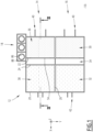
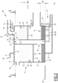
- FIGS 1 and 2 show an industrial plant 10 according to an embodiment of the invention.
- the industrial plant 10 is designed for gas treatment.
- the industrial plant 10 is designed for post-combustion carbon capture, as detailed below.
- the industrial plant 10 comprises : a wall assembly 12 ; at least a gas treatment unit 14, 16 ; and a pump unit 18.
- the wall assembly 12 forms a built structure of the industrial plant 10.
- the wall assembly 12 comprises : outer lateral walls 20 ; inner lateral walls 22, 24, 26 ; a top wall 27 ; and a bottom wall 28.
- the outer and inner lateral walls extend substantially vertically.
- the top and bottom walls extend substantially horizontally.
- the outer lateral walls 20 substantially extend along (X, Z) and (Y, Z) planes, the wall assembly 12 thus having a substantially rectangular base surface.
- the wall assembly 12 comprises a first 22 and a second 24 inner lateral walls, extending along (Y, Z) planes. In the embodiment of Figures 1 and 2 , the wall assembly 12 also comprises a third inner lateral wall 26, extending along a (X, Z) plane.
- the wall assembly 12 is made of materials adapted for a bearing structure, such as concrete or stainless steel.
- the industrial plant 10 comprises at least a first gas treatment unit 14, received in the wall assembly 12.
- the industrial plant 10 comprises a first 14 and a second 16 gas treatment units, received in the wall assembly 12.
- the first 14 and second 16 gas treatment units are at least partially isolated from each other by the third inner lateral wall 26.
- first 14 and second 16 gas treatment units are considered identical and disposed in parallel. Only the first gas treatment unit 14 will be described below.
- the first gas treatment unit 14 comprises : a first 30, a second 32 and a third 34 compartments ; a first 36 and a second 38 porous structures ; a gas inlet 40 ; a first 42 and a second 44 gas outlets ; a first 46 and a second 48 liquid inlets ; a first 50 and a second 52 liquid outlets ; and a first 54 and a second 56 openings.
- the first 30, second 32 and third 34 compartments are defined by the wall assembly 12. More specifically, the first 30, third 34 and second 32 compartments are aligned along the direction X between outer walls 20 of the wall assembly 12. The first 30 and third 34 compartments are separated from each other by the first inner lateral wall 22. The third 34 and second 32 compartments are separated from each other by the second inner lateral wall 24.
- Each of the first 30, second 32 and third 34 compartments extends vertically between an upper end and a lower end.
- a height along Z of the compartments 30, 32, 34 is more than 10 meters, more preferably around 20 meters.
- each of the first 36 and second 38 porous structures is disposed respectively in the first 30 and in the second 32 compartments.
- each of the first 36 and second 38 porous structures comprises a porous support 60, 62 and a structural packing 64, 66.
- the porous support 60, 62 such as a grid, extends horizontally and is fixed to the outer 20 and inner 22, 24, 26 lateral walls defining the corresponding first or second compartment 30, 32.
- the porous support 60, 62 is disposed at a first non-zero distance from the top wall 27 and at a second non-zero distance from the bottom wall 28.
- the porous support 60, 62 is disposed at a height comprised between 10% and 70% of a height of the corresponding compartment 30, 32, relative to the bottom wall 28.
- the structural packing 64, 66 is disposed on the corresponding porous support 60, 62, so as to form the corresponding porous structure 36, 38.
- the porous structure 36, 38 is designed for allowing contact between a gas and a liquid.
- the physical and/or chemical features of the structural packing 64, 66 are selected accordingly, as illustrated by the examples below.
- the gas inlet 40 opens at the lower end of the first compartment 30, below the porous support 60 of the first porous structure 36. In the embodiment of Figures 1 and 2 , the gas inlet 40 opens in an outer lateral wall 20 defining the first compartment 30.
- the gas inlet 40 is situated at a non-zero vertical distance 68 from the bottom wall 28. More precisely, between the bottom wall 28 and the gas inlet 40, the lower end of the first compartment 30 forms a first liquid tank 70.
- the first gas outlet 42 opens at the upper end of the second compartment 32, above the second porous structure 38.
- the first gas outlet 42 opens in an outer lateral wall 20 defining the second compartment 32.
- the first gas outlet opens in the top wall 27.
- the second gas outlet 44 opens at the upper end of the first compartment 30, above the first porous structure 36. In the embodiment of Figures 1 and 2 , the second gas outlet 44 opens in the top wall 27.
- each of the first 46 and second 48 liquid inlets open at the upper ends, respectively of the first 30 and of the second 32 compartments, above the corresponding porous structure 36, 38.
- each of the first 46 and second 48 liquid inlets comprises nozzles 72 or sprinklers, fixed to the top wall 27.
- each of the first 46 and second 48 liquid inlets open in an outer lateral wall 20 of the corresponding compartment 30, 32 and is connected to a dispensing device extending over the corresponding porous structure 36, 38.
- the first liquid inlet 46 is configured for pouring a first liquid 74 on the first porous structure 36.
- the second liquid inlet 48 is configured for pouring a second liquid 75 on the second porous structure 38.
- the first gas treatment unit 14 also comprises external coolers (not shown) for cooling the first liquid 74 upstream from the first liquid inlet 46.
- the first 50 and second 52 liquid outlets open at the lower ends, respectively of the first 30 and of the second 32 compartments, below the corresponding porous structure 36, 38.
- each of the first 50 and second 52 liquid outlets opens in the bottom wall 28.
- the first opening 54 is formed between the first 30 and the third 34 compartments, above the first porous structure 36.
- the first opening 54 is formed in an upper end of the first inner lateral wall 22.
- the second opening 56 is formed between the third 34 and the second 32 compartments, below the second porous structure 38.
- the second opening 56 is formed in a lower end of the second inner lateral wall 24.
- the second opening 56 is situated at a non-zero vertical distance 76 from the bottom wall 28. More precisely, between the bottom wall 28 and the second opening 56, the lower end of the second compartment 32 forms a second liquid tank 78.
- the first 50 and second 52 liquid outlets open respectively in the first 70 and in the second 78 liquid tanks.
- the first gas treatment unit 14 also comprises : a gas connection 80 ; a first 82 and a second 83 vanes ; and a temperature probe 84.
- the gas connection 80 extends from the second gas outlet 44 and will be further described below.
- the first vane 82 is configured for reversibly closing the second gas outlet 44.
- the second vane 83 is configured for reversibly closing the first opening 54.
- the first gas treatment unit 14 also comprises a third vane (not shown) for reversibly closing the second opening 56.
- the temperature probe 84 is situated in the first compartment 30, above the first porous structure 36, preferably close to the first opening 54.
- the pump unit 18 is configured for evacuating the first 74 and/or second 75 liquid from the corresponding first 70 or second 78 liquid tank.
- the pump unit 18 comprises at least one pump 86 able to be connected to the first 50 and/or to the second 52 liquid outlet.
- each of the first 50 and the second 52 liquid outlets is connected to a distinct pump 86.
- the pump unit 18 comprises at least one sump 88 receiving the at least one pump 86.
- the bottom wall 28 of the wall assembly 12 is level to a ground 90 on which the wall assembly is built, whereas the sump 88 is partially buried in said ground. It is therefore possible to use a submersion pump 86 by fluidly connecting the first 70 or second 78 liquid tank, or the first 50 or second 52 liquid outlet, with the sump 88.
- At least some of the sumps 88 are level with the bottom wall 28.
- the pump unit 18 comprises a plurality of pumps 86 and an individual sump 88 for each of said pumps 86.
- At least some pumps 86 of the pump unit 18 are also able to be connected to the liquid outlets of the second gas treatment unit 16.
- the pump unit 18 is common to the first 14 and second 16 gas treatment units.
- the industrial plant 10 is designed for post-combustion carbon capture. More precisely, the gas inlet 40 is connected to a flue gas source (not shown), such as a power plant. In the embodiment of Figures 1 and 2 , the gas connection 80 extends to said power plant for recycling the flue gas, as described below.
- a flue gas source not shown
- the gas connection 80 extends to said power plant for recycling the flue gas, as described below.
- each gas treatment unit having its own gas inlet 40.
- the gas inlet 40 of each of the gas treatment units 14, 16 has a cross-section shaped as a 6 m ⁇ 6 m square.
- the first compartment 30 is a direct contact cooler (DCC), designed for cooling the flue gas entering the industrial plant 10.
- the first liquid 74 is cold water.
- the structural packing 64 of the first porous structure 36 is chosen among metal or plastic grids and metal or plastic woven mesh.
- the structural packing 64 is made of metal, plastic, or ceramic thin vertical crimped sheets,stacked parallel to each other.
- the first compartment 30 comprises a supplementary gas inlet 92, allowing to add a supplementary gas to the flue gas entering the first compartment.
- the supplementary gas comprises treatment chemicals such as ammonia or acids.
- the second compartment 32 is an absorber column, designed for removing CO 2 from the flue gas by absorbing it into the second liquid 75.
- the second liquid 75 is chosen among solvents such as amines ; and the structural packing 66 of the second porous structure 38 is preferably chosen among metal or plastic grids and metal or plastic woven mesh.
- amines means an aqueous liquor made of water plus amine molecule having a concentration between 20%wt to 70%wt.
- the structural packing 66 is made of metal, plastic, or ceramic thin vertical crimped sheets,stacked parallel to each other.
- a flux of flue gas enters the first compartment 30 of a gas treatment unit 14, 16 through the gas inlet 40 and moves upwards through the packing 64 of the first porous structure 36.
- a flux of the first liquid 74 here cold water, is poured or sprinkled on said first porous structure 36 and moves downwards.
- the resulting counter-current contact between the flue gas and the cold water 74 in the first porous structure 36 allows a heat exchange between said gas and said water.
- the gas flux attaining the upper end of the first compartment 30 is therefore cooled.
- the heated water is collected in the first liquid tank 70.
- the first liquid 74 is a cold solution of caustic soda or of a similar compound.
- the contact between the flue gas and the first liquid 74 in the first porous structure 36 also allows the removal of some contaminants.
- the first porous structure 36 thus has a pre-scrubbing function.
- a supplementary gas is injected through the supplementary gas inlet 92. Other contaminants are thus removed by the passage of the flue gas in the first porous structure 36.
- a temperature of the gas flux attaining the upper end of the first compartment 30 is measured by the probe 84. If said temperature is above a defined threshold, parameters of the external coolers (not shown) of the first liquid may be modified.
- the defined threshold is comprised between 40 °C and 65 °C.
- the first vane 82 is closed and the second vane 83 is at least partially opened.
- the gas flux moves downwards through the third compartment 34, and then enters the second compartment 32 through the second opening 56.
- the gas flux then moves upwards through the packing 66 of the second porous structure 38.
- a flux of the second liquid 75 is poured or sprinkled on said second porous structure 38 and moves downwards.
- the resulting counter-current contact between the gas flux and the second liquid 75 in the second porous structure 38 allows a capture of the CO 2 of the gas flux into the second liquid 75.
- an operating pressure of the plant 10 is close to the atmospheric pressure.
- the COs-depleted gas flux is then evacuated through the first gas outlet 42, above the second porous structure 38.
- the CO 2 -depleted gas flux is released into the atmosphere through appropriate means such as a chimney.
- the first gas outlet 42 is connected to a supplementary treatment column.
- the CO 2 -charged solvent is collected in the second liquid tank 78.
- the liquids filling the first 70 and second 78 liquid tanks are evacuated by connecting a pump 86 of the pump unit 18, or the corresponding sump 88, to the first 50 or to the second 52 liquid outlet.
- the plurality of pumps 86 and sumps 88 of the pump unit 18 allows a sharing of the pumps between the different gas treatment units 14, 16 of the industrial plant 10.
- Each pump 86 having its individual sump 88 simplify the maintenance operations on a specific pump 86, by fluidly isolating the corresponding sump. The maintenance operations may therefore be carried out during a working of the other pumps of the pump unit 18.
- the second vane 83 is closed and the first vane 82 is opened.
- the gas flux is redirected to the power plant through the gas connection 80.
- the flue gas attaining the second gas outlet 44 still contains oxygen, which is useful for combustion of fuel gas in some types of power plants.
- a cooled flue gas redirected to the power plant is beneficial to power output from said power plant.
- the gas treatments unit 14, 16 described above allow the use of the direct contact cooler 30, 36 for two different treatments of the incoming flue gas.
- the second gas outlet 44 of the first gas treatment unit 14 is connected to the gas inlet 40 of the second gas treatment unit 16. According to such an embodiment, it is possible to direct the flue gas on two successive direct contact coolers 30, 36 before orienting the flue gas to the absorber column 32, 38 or back to the power plant.
Landscapes
- Chemical & Material Sciences (AREA)
- Engineering & Computer Science (AREA)
- Analytical Chemistry (AREA)
- General Chemical & Material Sciences (AREA)
- Oil, Petroleum & Natural Gas (AREA)
- Chemical Kinetics & Catalysis (AREA)
- Environmental & Geological Engineering (AREA)
- Health & Medical Sciences (AREA)
- Biomedical Technology (AREA)
- Treating Waste Gases (AREA)
- Incineration Of Waste (AREA)
Priority Applications (3)
| Application Number | Priority Date | Filing Date | Title |
|---|---|---|---|
| EP23305078.0A EP4403249A1 (de) | 2023-01-23 | 2023-01-23 | Industrieanlage zur gasbehandlung |
| PCT/EP2024/051428 WO2024156662A1 (en) | 2023-01-23 | 2024-01-22 | Industrial plant for gas treatment |
| AU2024211018A AU2024211018A1 (en) | 2023-01-23 | 2024-01-22 | Industrial plant for gas treatment |
Applications Claiming Priority (1)
| Application Number | Priority Date | Filing Date | Title |
|---|---|---|---|
| EP23305078.0A EP4403249A1 (de) | 2023-01-23 | 2023-01-23 | Industrieanlage zur gasbehandlung |
Publications (1)
| Publication Number | Publication Date |
|---|---|
| EP4403249A1 true EP4403249A1 (de) | 2024-07-24 |
Family
ID=85328638
Family Applications (1)
| Application Number | Title | Priority Date | Filing Date |
|---|---|---|---|
| EP23305078.0A Pending EP4403249A1 (de) | 2023-01-23 | 2023-01-23 | Industrieanlage zur gasbehandlung |
Country Status (3)
| Country | Link |
|---|---|
| EP (1) | EP4403249A1 (de) |
| AU (1) | AU2024211018A1 (de) |
| WO (1) | WO2024156662A1 (de) |
Citations (5)
| Publication number | Priority date | Publication date | Assignee | Title |
|---|---|---|---|---|
| EP2520352A1 (de) * | 2011-05-02 | 2012-11-07 | Alstom Technology Ltd | Gas- bzw. Flüssigkeitskontaktbehälter und Verwendung davon in einem Rauchgasbehandlungssystem |
| US20130098248A1 (en) * | 2010-07-29 | 2013-04-25 | Mitsubishi Heavy Industries, Ltd. | Gas-liquid contactor and co2 recovery unit |
| US20160001223A1 (en) * | 2013-04-26 | 2016-01-07 | Ihi Corporation | Recovery method and recovery apparatus of carbon dioxide |
| CN110615409A (zh) * | 2019-09-16 | 2019-12-27 | 安徽华铂再生资源科技有限公司 | 一种基于冶炼系统的二氧化硫烟气制酸工艺 |
| US20220193606A1 (en) * | 2020-12-21 | 2022-06-23 | Carbon Engineering Ltd. | Capturing carbon dioxide |
Family Cites Families (2)
| Publication number | Priority date | Publication date | Assignee | Title |
|---|---|---|---|---|
| DE3903510A1 (de) * | 1989-02-06 | 1990-08-09 | Gottlob Schwarzwaelder | Vorrichtung zum entfernen fluechtiger loesungsmittel und sonstiger umweltbelastender stoffe aus abgasen |
| CN107441908A (zh) * | 2017-08-17 | 2017-12-08 | 泸州川西化玻璃钢有限公司 | 一种工业废气集中处理系统 |
-
2023
- 2023-01-23 EP EP23305078.0A patent/EP4403249A1/de active Pending
-
2024
- 2024-01-22 WO PCT/EP2024/051428 patent/WO2024156662A1/en not_active Ceased
- 2024-01-22 AU AU2024211018A patent/AU2024211018A1/en active Pending
Patent Citations (5)
| Publication number | Priority date | Publication date | Assignee | Title |
|---|---|---|---|---|
| US20130098248A1 (en) * | 2010-07-29 | 2013-04-25 | Mitsubishi Heavy Industries, Ltd. | Gas-liquid contactor and co2 recovery unit |
| EP2520352A1 (de) * | 2011-05-02 | 2012-11-07 | Alstom Technology Ltd | Gas- bzw. Flüssigkeitskontaktbehälter und Verwendung davon in einem Rauchgasbehandlungssystem |
| US20160001223A1 (en) * | 2013-04-26 | 2016-01-07 | Ihi Corporation | Recovery method and recovery apparatus of carbon dioxide |
| CN110615409A (zh) * | 2019-09-16 | 2019-12-27 | 安徽华铂再生资源科技有限公司 | 一种基于冶炼系统的二氧化硫烟气制酸工艺 |
| US20220193606A1 (en) * | 2020-12-21 | 2022-06-23 | Carbon Engineering Ltd. | Capturing carbon dioxide |
Also Published As
| Publication number | Publication date |
|---|---|
| WO2024156662A1 (en) | 2024-08-02 |
| AU2024211018A1 (en) | 2025-08-07 |
Similar Documents
| Publication | Publication Date | Title |
|---|---|---|
| RU2644918C2 (ru) | Распределительная пластина для газожидкостной контактной колонны с системой вторичного распределения | |
| RU2451251C1 (ru) | Установка комплексной подготовки газа газового промысла нефтегазоконденсатного месторождения | |
| CN101288823B (zh) | 一种海船排烟洗涤装置及洗涤方法 | |
| EP2520352B1 (de) | Gas- bzw. flüssigkeitskontaktbehälter und verwendung davon in einem rauchgasbehandlungssystem | |
| WO2024156662A1 (en) | Industrial plant for gas treatment | |
| CA2176105A1 (en) | Device for cleaning gases, such as exhaust gases and/or synthesis gases | |
| CN101793348A (zh) | 蒸汽储能罐 | |
| US948432A (en) | Condenser. | |
| CN214486234U (zh) | 一种压力容器气液分离装置 | |
| RU2446000C1 (ru) | Универсальная массообменная абсорбционно-десорбционная установка | |
| UA118984C2 (uk) | Деаератор (варіанти) | |
| RU76338U1 (ru) | Установка для переработки нефти и газового конденсата | |
| CN211078530U (zh) | 一种真空填料蒸发及冷凝排液装置 | |
| RU2452556C1 (ru) | Установка улавливания углеводородных паров | |
| CN201050795Y (zh) | 分仓式烟气脱硫吸收塔 | |
| KR102937957B1 (ko) | 진공증발 농축기 | |
| SU1695117A1 (ru) | Эжекционный охладитель | |
| CN108654320B (zh) | 一种新型酸雾净化塔 | |
| CN101816840A (zh) | 一种下进气含酯尾气多级净化回收装置 | |
| CN204265774U (zh) | 喷雾型钢渣热焖蒸汽防爆处理装置 | |
| JPH10232001A (ja) | ヒートパイプ蒸気凝縮器用一体式脱気装置 | |
| SU1555298A1 (ru) | Магнитный аппарат дл очистки жидкостей и газов от ферромагнитных примесей и магнитной обработки водных систем | |
| CN204151361U (zh) | 喷雾型钢渣热焖焖盖防爆蒸汽处理装置 | |
| CN115364507B (zh) | 一种除盐及二元混合一体化冷凝器 | |
| RU2816915C1 (ru) | Устройство десорбции метанола |
Legal Events
| Date | Code | Title | Description |
|---|---|---|---|
| PUAI | Public reference made under article 153(3) epc to a published international application that has entered the european phase |
Free format text: ORIGINAL CODE: 0009012 |
|
| STAA | Information on the status of an ep patent application or granted ep patent |
Free format text: STATUS: THE APPLICATION HAS BEEN PUBLISHED |
|
| AK | Designated contracting states |
Kind code of ref document: A1 Designated state(s): AL AT BE BG CH CY CZ DE DK EE ES FI FR GB GR HR HU IE IS IT LI LT LU LV MC ME MK MT NL NO PL PT RO RS SE SI SK SM TR |
|
| STAA | Information on the status of an ep patent application or granted ep patent |
Free format text: STATUS: REQUEST FOR EXAMINATION WAS MADE |
|
| 17P | Request for examination filed |
Effective date: 20250124 |
|
| P01 | Opt-out of the competence of the unified patent court (upc) registered |
Free format text: CASE NUMBER: APP_13033/2025 Effective date: 20250317 |