EP4402494B1 - Vorrichtung zur überwachung des isolationszustandes und entsprechendes datenverarbeitungssystem - Google Patents
Vorrichtung zur überwachung des isolationszustandes und entsprechendes datenverarbeitungssystem Download PDFInfo
- Publication number
- EP4402494B1 EP4402494B1 EP21778015.4A EP21778015A EP4402494B1 EP 4402494 B1 EP4402494 B1 EP 4402494B1 EP 21778015 A EP21778015 A EP 21778015A EP 4402494 B1 EP4402494 B1 EP 4402494B1
- Authority
- EP
- European Patent Office
- Prior art keywords
- data
- insulator
- server
- sensors
- values
- Prior art date
- Legal status (The legal status is an assumption and is not a legal conclusion. Google has not performed a legal analysis and makes no representation as to the accuracy of the status listed.)
- Active
Links
Images


Classifications
-
- G—PHYSICS
- G01—MEASURING; TESTING
- G01R—MEASURING ELECTRIC VARIABLES; MEASURING MAGNETIC VARIABLES
- G01R31/00—Arrangements for testing electric properties; Arrangements for locating electric faults; Arrangements for electrical testing characterised by what is being tested not provided for elsewhere
- G01R31/12—Testing dielectric strength or breakdown voltage ; Testing or monitoring effectiveness or level of insulation, e.g. of a cable or of an apparatus, for example using partial discharge measurements; Electrostatic testing
- G01R31/1227—Testing dielectric strength or breakdown voltage ; Testing or monitoring effectiveness or level of insulation, e.g. of a cable or of an apparatus, for example using partial discharge measurements; Electrostatic testing of components, parts or materials
- G01R31/1245—Testing dielectric strength or breakdown voltage ; Testing or monitoring effectiveness or level of insulation, e.g. of a cable or of an apparatus, for example using partial discharge measurements; Electrostatic testing of components, parts or materials of line insulators or spacers, e.g. ceramic overhead line cap insulators; of insulators in HV bushings
-
- G—PHYSICS
- G01—MEASURING; TESTING
- G01R—MEASURING ELECTRIC VARIABLES; MEASURING MAGNETIC VARIABLES
- G01R31/00—Arrangements for testing electric properties; Arrangements for locating electric faults; Arrangements for electrical testing characterised by what is being tested not provided for elsewhere
- G01R31/08—Locating faults in cables, transmission lines, or networks
- G01R31/081—Locating faults in cables, transmission lines, or networks according to type of conductors
- G01R31/085—Locating faults in cables, transmission lines, or networks according to type of conductors in power transmission or distribution lines, e.g. overhead
-
- H—ELECTRICITY
- H01—ELECTRIC ELEMENTS
- H01B—CABLES; CONDUCTORS; INSULATORS; SELECTION OF MATERIALS FOR THEIR CONDUCTIVE, INSULATING OR DIELECTRIC PROPERTIES
- H01B17/00—Insulators or insulating bodies characterised by their form
- H01B17/005—Insulators structurally associated with built-in electrical equipment
Definitions
- the present disclosure relates to an insulator condition monitoring device and the corresponding data processing system.
- the invention's technical field belongs to testing electric properties in general, and more specifically, it belongs to arrangements for locating electric faults of line insulators or spacers, e.g., ceramic overhead line cap insulators.
- Insulator condition monitoring represents, among others, a standard routine in every power grid maintenance and checking. It is known in the art that severe environmental and industrial pollution is a concern for electric utilities due possible resulting flashovers and unplanned line outages. In this regard, insulator condition monitoring is a valuable tool to allow maintenance actions, such as washing, to be scheduled when needed.
- leakage current stands out as the most meaningful since it provides a true measure of how close an insulator string is to flashover.
- the relationship between leakage current and environmental as well as climatic factors that can impact insulators has therefore attracted much attention. But since this relationship is complex and dynamic it cannot be successfully described using mathematical tools only, even combined with environmental and meteorological data with the help of machine learning.
- the present disclosure is therefore oriented toward novel, reliable, cheap, and easy to use condition monitoring device per se and the corresponding data processing system.
- the disclosed monitoring device is equipped with a plurality of sensors used for monitoring electrical and mechanical properties of the insulator and the insulator unit to which is mounted.
- each monitoring device is equipped with a low-power wide-area network (LPWAN) unit, capable to exchange the data with one or more LPWAN gateways in a way that does not support full duplex communication and wakening the said devices on the server's demand.
- LPWAN low-power wide-area network
- the data processing system is designed to monitor a plurality of the above cited monitoring devices that are mounted in geographic areas capable to drastically change environmental properties for one day, which significantly alter the insulator behaviour in the electric sense. So, the first technical problem is the design of the data processing system that is capable to handle the plurality of the monitoring devices in a manner which preserves their batteries, disables false alarms, or prevents devices' rapid data firing especially from new installed devices.
- the second technical problem solved with the present invention is the way of combining received data of identical or different set of sensors from two or more monitoring devices. Namely, data corelation, optionally combined with meteorological and geographic data, significantly improves knowledge about the insulators that surpass any mathematical models known in the art. In addition, the corelation among sensor data of single and multiple monitoring devices are used for generating health reports not only for the single insulator but for all power lines under surveillance.
- the third technical problem is oriented to the monitoring device per se .
- the device is designed, according to the preferred embodiment, to be attached with the simple cable tie to the insulator, without necessity to disconnect the corresponding line conductor and without need for enclosing the insulator with the measuring coils or transformers.
- the disclosed devices and the corresponding data processing system can be effectively used in a standard control or periodic tests performed on a transmission or distribution lines with a standard high-voltage test methods.
- the data-processing system for monitoring working condition of electric insulators pre-sets one or more devices to respond to performed tests using the sensors and probes of the said devices to further check the condition of the transmission line or to determine the location of faults, without interfering with the results of the said tests.
- Document JPS6333670A for the invention SYSTEM FOR MONITORING CONTAMINATION CORONA OF TRANSMISSION LINE discloses the device which is mounted directly on the insulator for monitoring purpose. This device has a current transformer which surrounds the insulator and the side mounted Hall probe as well.
- the device, according to the present invention has more sensors, i.e., an inclination and acceleration sensor, several magnetic field sensors, LPWAN communication unit, etc. The document is silent regarding possible use of correlation among the used sensors from the same or different devices.
- Document CN110261750A for the invention POLLUTION FLASHOVER MONITORING DEVICE AND METHOD OF ELECTRIC TRANSMISSION LINE INSULATOR STRING, filed in the name of Yunnan Power Grid Co., Ltd. and Electric Power Research Institute, discloses a yet another monitoring device.
- the main sensor the document mentions clamp-type ammeter that enables a measurement of the current in a conductor without the need to make physical contact with it.
- the described device is further equipped with a wireless long-distance data transmission module, and with a humidity and a temperature sensor.
- the document is silent regarding the usage of an acceleration or an inclination sensor for monitoring mechanical parameters or other electromagnetic parameters such as Hall probes, electric field antennas or similar.
- a transmitting device that is configured to transmit a signal, including the information sensed by the Rogowski coil, away from the insulator leakage current detector is a RFID sensor, because the RFID sensor does not require a separate power source to transmit a signal.
- Document CN106353656A for the invention MONITORING METHOD AND MONITORING DEVICE OF INSULATOR FLASHOVER CURRENT filed in the name of Dongguan Power Supply Bureau Guangdong Power Grid Co. Ltd. Et Al., discloses yet another monitoring device with the Rogowski coil mounted over the insulator.
- the wireless communication module supports General Packet Radio Service (GPRS) and a short message dual channel transmission data and supports multi-center data communication. It is interesting that the cited invention uses an external data processing system to receive the above threshold monitored data, such as the flashover data. This document is silent regarding other sensors and using the correlation data from one or more sensors.
- GPRS General Packet Radio Service
- the present invention seems to be silent regarding the use of combination of identical sensors from two or more identical devices for monitoring insulators' properties over the same power line.
- the disclosed device is oriented solely to a sag monitoring and not to insulator properties monitoring, i.e., it has a mechanical property that is not suitable to be mounted over around the insulator unit, and it is directed to monitor different operating conditions.
- the sensor mounting system and other disadvantages, such as the module(s) power consumption may prevent the above-described systems real usage on the power grid.
- the disclosed invention is oriented to a method of operating a data-processing system for monitoring the working condition of electric insulators according to claim 1 and the associated data-processing system according to claim 2.
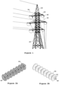
- Figure 1 depicts a standard transmission tower (20), that carries one or more phase conductors (30), and where each conductor (30) is isolated from the tower with set of insulators (40). It is evident that mounting position of the said insulators (40) represents the problem per se and is necessary to reduce manpower that is necessary to maintain said insulators (40) in a workable condition that deteriorates in time due to the various factors.
- Each insulator (40), depicted on Figures 2A-2C is composed from number of insulator units (50), where the insulator condition monitoring device (10) is mounted over the outer side of the first insulator unit (50).
- Plurality of insulator units (50) compose the insulator (40) in a simple and reliable manner, each unit (50) has its pin (51) and the cap (52) that is capable to receive the said pin (51), as depicted in Figures 3A-3C .
- stacking of the insulator units (50) is achieved, in a manner that is well known in the art, to produce stacked insulator (40) chain or string.
- the number of used insulating units (50) defines the highest insulating voltage breakdown, e.g., the isolation ability.
- the best position for mounting the monitoring device (10) is at the beginning of the insulator (40), i.e., on the outer side of the first insulating unit (50) where the said device (10) does not alter the insulator (40) properties, that is not the case with all cited prior art. Namely, such mounting affects only the first insulating unit (50), located closely to the transmission tower (20). The actual geometry of such mounting is clearly visible on Figures 3B and 4 .
- the device (10) is conceived as an integral device which is mounted directly to the desired insulator unit (50), without necessity to disconnect the corresponding line conductor (30). Said mounting is performed, preferably via the fastening means such as a cable tie, capable to be tighten via the hot stick designed for the said purpose.
- enclosing the insulator unit (50) has nothing with the sensing characteristic of the device (10). Namely, the used fastening means are entirely free from coils, such as the Rogowski coil, or amp clamp meters which require skilled person to assure proper mounting of such devices.
- the device (10) it is also possible to fix the device (10) to an insulator unit (50) via gluing or by using adhesives that hardens once exposed to the ultra-violet light.
- the exchange of the used device (10) may be a potential problem.
- the plastic cable tie seems to be the cost-effective approach to the mounting-dismounting problem.
- the insulator condition monitoring device (10) should be reliable, cheap, and easy to use.
- the monitoring device (10) is equipped with the hall probe (11), one or more electric field sensors (12.i), one or more magnetic field sensors (13.j) and the acceleration and inclination sensor (14). Furthermore, the said device (10) has the inner temperature sensor (18). All these sensors and the used probe are connected to the processing unit (15).
- the battery with its battery management system (17) is designed to supply the necessary power for the operation of the entire device (10).
- the device (10) has LPWAN (Low Power Wide Area Network) module installed for the communication purpose, that is also connected with the processing unit (15) and the battery with its battery management system (17), as depicted on Figures 4 and 5 .
- LPWAN Low Power Wide Area Network
- hall probe (11) The technical role of hall probe (11) is that is capable to sense electric flashover from the corresponding phase conductor (30) and the tower (20) which holds the same phase conductor (30).
- the output from said hall probe (11) is basically 0 or 1, and the hall probe has to be chosen in a manner to prevent any low leakage current triggering.
- the hall probe 595-DRV5032FBDBZR produced by Texas Instruments ® , is used.
- electric field sensors (12.i) The technical role of electric field sensors (12.i) is to capture different spectrum parts of the radio frequency (RF) signals generated in vicinity of the said insulator unit (50). Considering the RF spectrum that has to be captured, i.e., from low frequencies up to 100 MHz, it is natural to have more than one RF detector for detecting electric field for various ranges where the antenna geometry basically defines the sensing range.
- the output from one or more electric field sensors (12.i) can be interpreted after analog-to-digital conversion (ADC) as one byte signal, i.e., 0-255, according to the preferred embodiment.
- ADC analog-to-digital conversion
- the electric field sensor uses partial discharge antennas, formed on a PCB (Printed Circuit Board), and designed by the applicant.
- magnetic field sensors (13.j) The technical role of magnetic field sensors (13.j) is to register the magnetic field vector magnitude in the desired orientation in vicinity of the said insulator unit (50). Therefore, it is natural to have more than one magnetic field sensors to measure the magnetic field vector around the device (10).
- the output from one or more magnetic field sensors (13.j) can be interpreted after analog-to-digital conversion (ADC) as one byte signal, i.e., 0-255, according to the preferred embodiment.
- ADC analog-to-digital conversion
- the magnetic field sensor is a small Rx Coil unit, model WR221230-36M8-G TDK ® .
- acceleration and inclination sensor (14) register any change in inclination and acceleration of the device (10).
- the said sensor (14) is provided with a free fall detection and triggering unit, that is found very useful.
- the free fall detection and triggering unit is used for wakening up the device (10) and alert the data processing system, which will be explained in more details latter.
- the output from acceleration and inclination sensor (14) can be written in one Byte format, i.e., 0-255, according to the preferred embodiment whilst the triggering signal, that corresponds to free fall detection, is standard 0 or 1 signal.
- the acceleration and inclination sensors are packed into AIS2IHTR MEMS Accelerometer, Digital, X, Y, Z, ⁇ 2g, ⁇ 4g, ⁇ 8g, ⁇ 16g, 1.62 V, 3.6 V, LGA, Farnell ® .
- temperature sensor (18) The technical role of temperature sensor (18) is to measure inner device (10) temperature.
- the output from temperature sensor (18) can be written in one Byte format, i.e., 0-255, according to the preferred embodiment. In the present invention, off-the-shelf generic temperature sensor is used.
- battery (17) and the corresponding battery management system is well known in the art. According to the preferred embodiment, it is possible to convert the battery status, i.e., the battery voltage, into one Byte format to be transmitted together with other sensors/probe data, such as ID number.
- the battery and battery management SAFT LS 17500 PFRP, produced by SAFT batteries is used.
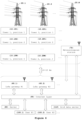
- low-power wide-area network (LPWAN) unit (17) The technical role of low-power wide-area network (LPWAN) unit (17) is to exchange the data with one or more LPWAN gateways (60), that are located 10-15 km away from used device (10).
- the LoRa module is used.
- LoRa is a proprietary Low-Power Wide-Area network modulation technique, based on spread spectrum modulation techniques, operating in different sub-GHz bands across the world, and with data rates from 0.3 - 27 kbit/s. Since LoRa defines the lower physical layer, the upper networking layers were lacking.
- LoRaWAN is one of several protocols that were developed to define the upper layers of the network.
- LoRaWAN is a cloud-based medium access control (MAC) layer protocol but acts mainly as a network layer protocol for managing communication between LPWAN gateways and end-node devices as a routing protocol, maintained by the LoRa Alliance.
- LoRaWAN defines the communication protocol and system architecture for the network, while the LoRa physical layer enables the long-range communication link.
- LoRaWAN is also responsible for managing the communication frequencies, data rate, and power for all devices. It is important to note that devices (17) in the network are asynchronous and transmit when they have data available to send or when triggered by any change of the state. Data transmitted by an end-node device is received by multiple gateways (60.i), which forward the data packets, via the Internet (90) to a centralized network server (80).
- LPWAN unit Lora Module ES0, Murata ® is used.
- processing unit (15) The technical role of processing unit (15) is to collect the data from the above listed probe (11) and sensors (12, 13, 14, 18) and to initiate transmission of the acquired data with the unique ID that defines the device. Having in mind the asynchronous nature of the data transmission over the LPWAN network, e.g., LoRa devices, the processing unit (15) is configured to receive the instructions via LPWAN gateways (60) how to manage the data in the next time frame, immediately after the send session terminates.
- the said processing unit (15) is configured in a way to be triggered by one or more triggering events to immediately send the data over its LPWAN unit (17). The said triggering events occur when default values of one or more sensors (12, 13, 14, 18) or probe (11) are exceeded, or when predefined time for automatic sending is expired.
- the processing unit (15) is formed as a simple microcontroller or SoC (system on chip) with modest computational capability in order to preserve the battery (17) lifetime. In the present invention, the processing unit Type ABZ-078, Murata ® is used
- the said device (10) is capable to run autonomously for more than a decade, with one in 24 hours data transmission towards LoRa Gateways (60).
- a LPWAN gateways e.g., LoRa gateways (60) are need for the proper operation of monitoring devices (10).
- Such LoRA gateways should be disposed over the power lines trace to provide a reliable connection with the mentioned devices (10), having in mind the nature of used asynchronous communication via LoRaWAN protocol.
- Said LoRa gateways (60) are, as mentioned, receiving and transmitting nodes that allow the devices (10) access to the Internet (90) and finally to a server (80) which is used as the data processing system for execution the method described in the details below.
- the important role plays meteorological stations (70) that provide meteorological data for the server (80).
- meteorological stations (70) that provide meteorological data for the server (80).
- one source of meteorological data, correlated with position are standard meteorological stations used in any other fields. So, the data are in that case transmitted directly, via the Internet (90), to the server (80), as depicted on Figure 6 .
- a local weather-stations can be mounted over one or more towers (30), that provide accurate temperature and humidity data, transmitted via the LPWAN unit to LPWAN gateways, or via a cellular modem directly to the server (80), using the Internet layer (90) in-between.
- Grid data server (110) represents any computer which is capable to provide the grid status data from the grid Supervisory Control and Data Acquisition (SCADA) system in any format, via the Internet layer (90), to the server (80).
- SCADA grid Supervisory Control and Data Acquisition
- the access to this data can be delivered in real time or periodically, and it is used in most cases for the event confirmation, once the event has been registered by one or more devices (10).
- the device (10') is mounted, it is activated via the magnetic switch or similar switching device and starts to collect the data that will be sent in a later time at predefined time for send.
- the server (80) receives the data from the new device (10'), in an instant communication between server (80) and device (10'), the server sets a default values for all sensors (12', 13', 14', 18') and the probe (11') for the said device (10') only if received data shows that the current electric insulator (40) and the corresponding phase conductor (30) are operational. This condition is important, otherwise a rapid data firing towards the server (80) is imminent once the power in the corresponding conductor (30) is restored. Finally, the said device (10') becomes the device (10) in further method steps.
- the massage format exchanged between any device (10) and the server (80) is a several bytes long vector, as depicted in Table 1 below, where 2 magnetic field sensors and one electric field sensor are used: Table 1 Probe/Sensor Min. value Max. Value Hall probe 0 1 El. Field #1 0 255 Mag. Field #1 0 255 Mag. Field #2 0 255 Temperature 0 255 Acceleration 0 1 X - orientation 0 255 Y - orientation 0 255 Z - orientation 0 255 Next send time 0 255
- the relation between one-Byte values and the actual data can be of any form, linear or non-linear.
- Triggering probes i.e., Hall probe and free fall detection, has values 0 which refers to disabled and 1 which refers to enabled triggering and instantaneous data sending.
- the device starts to collect the data and send the data in predefined timeframe, for instance 1 hour timeframe, as obvious from the above table.
- the newly installed device (10') will report back to the server (80) recently measured data, as depicted in Table 3: Table 3 First measurement data Probe/Sensor Measured Hall probe 0 - disabled El. Field #1 75 Mag. Field #1 25 Mag. Field #2 2 Temperature 80 Acceleration 0 - disabled X - orientation 156 Y - orientation 211 Z - orientation 7
- the server (80) sends the following thresholds-data back to the said device (10'), see Table 4: Table 4 Server instructions for device (10') Probe/Sensor Thresholds / triggering Hall probe 1 - enabled El. Field #1 79 Mag. Field #1 27 Mag. Field #2 3 Temperature 84 Acceleration 1 - enabled X - orientation 156 Y - orientation 211 Z - orientation 7 Next send time 255 where the threshold values for electrical and magnetic field as well for the temperature are augmented for approx. 5-15% to prevent rapid firing data back, and where the Next_send_time is set to maximum, e.g., 24 hours.
- X, Y, Z orientation is not of the vital importance for the system and that the said changes are not able to trigger the system.
- these values are duly recorded in the server (80) and compared on each receiving sessions in order to establish any inclination problem. In case of serious problems with the insulator, i.e., the fall of it - the acceleration triggering will do the job.
- the server (80) can monitor X, Y, Z orientation, and if the newly recorded values deviate significantly, i.e., more than 5% or 10%, the inclination the problem with some insulator (40) is established and the corresponding actions can be triggered from the server's side on the system.
- the new device (10') become the standard installed device (10), which will send the data immediately to the server (80) if:
- Step C is performed simultaneously with step A. or step B.
- the server (80) permanently collects data obtained from plurality of devices (10), previously installed on the operational or non-operational part of the grid, which periodically send data to the server (80). This data-collection occurs all the time, the data are recorded for each device (10) in a manner that allows easy history checking data.
- analytic tasks carried out by the server (80) on data received in step C., data received from one or more meteorological stations (70), and optionally the data received from the grid data server (110), if any.
- Said analytic task is executed all the time and gives precious data for understanding the situation with the power grin in the field.
- Step E. is devoted to the data handling.
- Each new data obtained in step D. are further used by the server (80):
- All above said health reports are accessible by one or more users (100) responsible for monitoring said power line system.
- the said health reports are eventually indirectly confirmed via data received from the grid data server (110), if such data are available.
- Example I one device, single sensor status
- step D the server (80) checks newly received values of each sensor or probe mounted on the device (10) alone that has just transmitted data to the server (80). If the newly acquired data are out of expected limits, the following insulator (40) health statuses, carrying the said device (10), are recorded:
- Example II one device, single sensor status + meteorological data
- the server (80) checks particular sensor's data on some device (10) combined with the meteorological data.
- one or more electric field sensors (12.i) record changes in the electrical field that are out of initially set values during the observed increased relative air humidity for some particular device (10); then, the health status, generated in step E., is unchanged. However, the triggering events are adjusted by the server (80) for the said device (10) and sent back to the said device (10), and the server (80) learns behaviour of this particular device (80) for observed humidity values.
- Example III one device, correlation of sensors' behaviour
- the server (80) also checks the correlation of two or more different newly received sensors' values belonging to the same device (10) alone, which are eventually combined with the meteorological data for the said device (10) location.
- the following health statuses of the insulator (40), carrying the said device (10), are recorded:
- Example IV two or more devices, same conductor
- the server (80) checks the correlation of identical set of recently received sensors values for two or more devices (10, 10', 10", ...) mounted over the electric insulators (40, 40', 40", ...), attached to the same phase conductor (30), on the same or different towers (20, 20', 20", ...) and where two by two devices (10, 10') are simultaneously compared.
- Example V three devices, different conductors
- the server (80) checks the correlation of identical set of recently received sensors values for two or more devices (10, 10', 10", ...) mounted over the electric insulators (40, 40', 40", ...) attached to the different phase conductor (30), on the same or different towers (20, 20', 20", ...); where three-by-three devices (10, 10', 10") are used.
- I-V are illustrative examples of the disclosed insulator condition monitoring devices (10, 10', ...) and the corresponding data processing system.
- the person skilled in the art will immediately recognised the potential of the above-described data processing system and use the same or similar correlations to build even more sophisticated monitoring systems.
- Example VI using the system in standard control or periodic tests
- the installed network of monitoring devices is extremely useful during the execution of a standard control or periodic tests performed on a transmission or distribution line with standard high-voltage test methods.
- the data-processing system for monitoring working condition of electric insulators pre-sets one or more devices (10, 10', ...) to respond to performed tests.
- the sensor or probe threshold can be set to their lowest values possible, so any disturbances in grid will activate one or more dedicated devices (10, 10', ...) and the corresponding sensors, causing a rapid data firing.
- such behaviour is not desirable regarding the battery energy conservation, but in this example, it is an advantage and necessary condition to operate.
- the devices (10, 10', 10", ...) can record these changes and immediately respond if the corresponding thresholds are set to lowest values. In that sense further checks of the transmission line conditions are possible and the system of devices (10, 10', ...) allows the server (80) to determine the location of faults, if any, without interfering with the results of the said tests.
- the present disclosure relates to an insulator condition monitoring device and the corresponding data processing system capable to perform various tasks, beside monitoring insulators.
- the industrial applicability is therefore obvious.
Landscapes
- Physics & Mathematics (AREA)
- General Physics & Mathematics (AREA)
- Chemical & Material Sciences (AREA)
- Engineering & Computer Science (AREA)
- Ceramic Engineering (AREA)
- Insulators (AREA)
- Testing Of Short-Circuits, Discontinuities, Leakage, Or Incorrect Line Connections (AREA)
Claims (2)
- Verfahren zum Betreiben eines Datenverarbeitungssystems zur Überwachung des Arbeitszustands von elektrischen Isolatoren (40), die aus einer Vielzahl von Isolatoreinheiten (50) gebildet sind, wobei die Isolatoren (40) an einem oder mehreren Sendetürmen (20) angebracht sind, um einen oder mehrere Phasenleiter (30) von den Türmen (20) zu isolieren; wobei das Verfahren Daten verwendet, die von Überwachungsvorrichtungen (10) erhalten werden, die an der Außenseite ausgewählter Isolatoreinheiten (50) befestigt sind, und- wobei jede Überwachungsvorrichtung (10) umfasst:(i) eine Hallsonde (11), die in der Lage ist, einen elektrischen Überschlag vom entsprechenden Phasenleiter (30) und dem Turm (20), der denselben Phasenleiter (30) hält, wahrzunehmen;(ii) einen oder mehrere elektrische Feldsensoren (12) zum Erfassen verschiedener Spektralanteile der in der Nähe der Isolatoreinheit (50) erzeugten Hochfrequenzsignale (RF);(iii) einen oder mehrere Magnetfeldsensoren (13), die jeweils in der Lage sind die Magnetfeldvektorgröße in der gewünschten Ausrichtung in der Nähe der Isolatoreinheit (50) zu registrieren;(iv) einen Beschleunigungs- und Neigungssensor (14), der in der Lage ist Beschleunigungs- und Neigungsdaten mit einer Freifallerkennung zu messen;(v) eine Vorrichtung (10) mit Innentemperatursensor (18);(vi) eine Low-Power-Wide-Area-Network-, (LPWAN)-Einheit (17), die in der Lage ist die Daten mit einem oder mehreren LPWAN-Gateways (60) auszutauschen;(vii) eine Batterie (17) und das entsprechende Batteriemanagementsystem;(viii) eine Verarbeitungseinheit (15), welche die Daten von den zuvor aufgelisteten Sonden und Sensoren sammelt, die erfassten Daten mit der eindeutigen ID, welche die Vorrichtung definiert, überträgt und unmittelbar nach Beendigung einer Sendesitzung über LPWAN-Gateways (60) von dem Datenverarbeitungssystem Anweisungen empfängt, wie die Daten im nächsten Zeitrahmen zu verwalten sind; wobei die Verarbeitungseinheit (15) durch ein oder mehrere auslösende Ereignisse ausgelöst wird, um die Daten umgehend über ihre LPWAN-Einheit (17) zu senden, wobei die auslösenden Ereignisse auftreten, wenn Standardwerte eines oder mehrerer Sensoren (12, 13, 14, 18) überschritten werden, oder die Auslösung durch die Hallsonde (11) oder die Freifallerkennung (14) initiiert wird, oder wenn die vordefinierte Zeit für automatisches Senden abgelaufen ist;- wobei ein Satz von LPWAN-Gateways (60) über der Übertragungsstromleitung unter Überwachung angeordnet sind, um einen sicheren Datenaustausch dem Satz von Überwachungsvorrichtungen (10) zu gewährleisten, wobei jedes LPWAN-Gateway (60) weiter mit dem Internet (90) verbunden ist;- wobei meteorologische Daten von einer oder mehreren meteorologischen Stationen (70) erhalten werden, die optional über den Sendetürmen (20) angeordnet und direkt mit der Internetschicht (90) oder über die dedizierten LPWAN-Einheiten mit den LPWAN-Gateways (60) verbunden sind;- optional einen Netzdatenserver (110), der mit der Internetschicht (90) verbunden ist und zum Bereitstellen der Netzstatusdaten aus dem Netzüberwachungs-, Steuerungs- und Datenerfassungssystem (SCADA-System) in der Lage ist;- wobei ein mit der Internetschicht (90) verbundener Server (80) das Verfahren ausführt und den mit dem Internet (90) verbundenen Benutzern (100) die Daten hinsichtlich des Arbeitszustands des überwachten Satzes elektrischer Isolatoren (40) bereitstellt, die von einer Vielzahl von Überwachungsvorrichtungen (10), meteorologischen Stationen (70) und optional einem Netzdatenserver (110) gesammelt wurden;wobei die Verfahrensschritte sind:a) Voreinstellen jeder Vorrichtung (10'), bei der alle auslösenden Ereignisse deaktiviert sind, wobei die eindeutige ID für die Vorrichtung (10') generiert und zusammen mit der zukünftigen Montageposition des entsprechenden elektrischen Isolators (40) auf dem Server (80) gespeichert wird;b) sobald die bestimmte Vorrichtung (10') physisch an der dedizierten Isolatoreinheit (50) angebracht und aktiviert ist, beginnt die Vorrichtung (10') damit, die Daten zu sammeln, und sendet die Daten in vordefinierten Zeitintervallen an den Server (80), wo der Server (80) die Auslöser einschaltet und Standardwerte für alle Sensoren (12', 13', 14', 18') und die Sonde (11') für die Vorrichtung (10') einstellt, sobald die gesammelten Daten der Vorrichtung zeigen, dass der aktuelle elektrische Isolator (40) und der entsprechende Phasenleiter (30) betriebsbereit sind, und die Vorrichtung (10') zur Vorrichtung (10) in Schritt C wird;c) gleichzeitig mit Schritt A. oder Schritt B. sammelt und speichert der Server (80) permanent neue Daten, die er von einer Vielzahl von Vorrichtungen (10) erhält, die zuvor auf dem betriebsbereiten oder nicht betriebsbereiten Teil des Netzes installiert wurden und die periodisch Daten an den Server (80) senden;d) der Server (80) führt unter Verwendung der in Schritt C. neu erhaltenen Daten, der von einer oder mehreren meteorologischen Stationen (70) erhaltenen Daten und optional der vom Netzdatenserver (110) erhaltenen Daten permanent analytische Aufgaben aus, wobei der Server (80):- die neu empfangenen Werte jedes Sensors oder jeder Sonde an jeder Vorrichtung (10) allein überprüft, die empfangenen Werte mit den meteorologischen Daten für den Standort der Vorrichtung (10) kombiniert und die neu empfangenen Werte mit den zuvor aufgezeichneten Werten für dieselbe Vorrichtung (10) vergleicht;- die Korrelation von zwei oder mehr verschiedenen, neu empfangenen Sensorwerten allein überprüft, die nur zu derselben Vorrichtung (10) gehören, und die Daten schließlich mit den meteorologischen Daten für den Standort der Vorrichtung (10) kombiniert;- die Korrelation eines identischen Satzes von kürzlich empfangenen Sensorwerten für zwei oder mehr Vorrichtungen (10, 10', 10", ...) überprüft, die über den elektrischen Isolatoren (40, 40', 40", ...), die an denselben Phasenleiter (30) angebracht sind, auf denselben oder verschiedenen Türmen (20, 20' , 20", ...) montiert sind; und- die Korrelation eines identischen Satzes von kürzlich empfangenen Sensorwerten für zwei oder mehr Vorrichtungen (10, 10', 10", ...) überprüft, die über den elektrischen Isolatoren (40, 40', 40", ...), die an den verschiedenen Phasenleitern (30, 30', 30", ...) angebracht sind, auf denselben oder verschiedenen Türmen (20, 20', 20", ...) montiert sind;e) alle in Schritt D. erhaltenen neuen Daten werden vom Server (80) verwendet:- um Sensoren und Sondenschwellenwerte für die ausgewählte Vorrichtung (10) zu aktualisieren, die eine solche Aktion benötigt, und den entsprechenden Zustandsbericht für die Vorrichtung (10) erzeugt, sodass der Server (80) der Aufgabe, Sensoren und Sondenschwellenwerte für die ausgewählte Vorrichtung (10) zu aktualisieren, Priorität einräumt, um die Nachricht erfolgreich an die ausgewählte Vorrichtung (10) zurückzusenden, während sie sich im Empfangsmodus befindet;- um den neuesten Zustandsbericht für jeden Isolator (40) mit den Empfehlungen hinsichtlich der Wartung zu erzeugen, und falls notwendig, erzeugt der Server (80) einen Alarm, der an einen oder mehrere vordefinierte Benutzer (100) übertragen wird;- um den neuesten Zustandsbericht für jeden Phasenleiter (30) zu erzeugen; und- um den neuesten Zustandsbericht und Empfehlungen für die unter Überwachung befindliche Stromleitung zu erzeugen;wobei alle zuvor genannten Zustandsberichte für einen oder mehrere Benutzer (100) zugänglich sind, die für die Überwachung des Stromleitungssystems verantwortlich sind, und wobei die Zustandsberichte schließlich indirekt durch Daten bestätigt werden, die, sofern verfügbar, vom Netzdatenserver (110) empfangen werden;wobei das Verfahren dadurch gekennzeichnet ist, dass in Schritt D.:I.) der Server (80) die Korrelation von zwei oder mehr verschiedenen neulich empfangenen Sensorwerten überprüft, die zur selben Vorrichtung (10) gehören, und die folgenden Gesundheitszustände des Isolators (40), der die Vorrichtung (10) trägt, aufgezeichnet werden:- die Hallsonde (11) ausgelöst wird, und ein oder mehrere elektrische Feldsensoren (12.i) Änderungen des elektrischen Feldes außerhalb der ursprünglich eingestellten Werte erfassen, und ein oder mehrere Magnetfeldsensoren (13.j) Änderungen außerhalb der ursprünglich eingestellten Werte erfassen;wobei solche gleichzeitigen Aufzeichnungen eine oder mehrere der nachfolgend ausgelisteten Ursachen signalisieren:(i) einen Kriechstrom durch das geerdete Teil, oder(ii) einen Ausfall des Isolators (40),wobei der in Schritt E. erzeugte Gesundheitszustand einen sofortigen Austausch des Isolators (40) und die Sendung eines Alarms an den dedizierten Benutzer (100) zur Folge hat;- die Hallsonde (11) zusammen mit den Messungen des Beschleunigungs- und Neigungssensors (14) ausgelöst wird, die außerhalb der ursprünglich eingestellten Schwellenwerte liegen; wobei solche gleichzeitigen Aufzeichnungen eine oder mehrere der nachfolgend aufgelisteten Ursachen signalisieren:(i) eine Entladung über den Isolator (40) oder(ii) eine physische Einwirkung durch einen Baum, Eis oder Schnee, oder(iii) ein Windproblem,wobei der in Schritt E. erzeugte Gesundheitszustand mit der Maßgabe unverändert bleibt, dass bei der nächsten regelmäßigen Überprüfung dieser Isolator (40) zu überprüfen ist;- die Hallsonde (11) ausgelöst wird, ein oder mehrere elektrische Feldsensoren (12.i) während der beobachteten erhöhten relativen Luftfeuchtigkeit Veränderungen des elektrischen Feldes aufzeichnen, die außerhalb der ursprünglich eingestellten Werte liegen; wobei solche gleichzeitigen Aufzeichnungen signalisieren:(i) Veränderungen im elektrischen Feld, wobei Feuchtigkeit eine Entladung über den Isolator (40) bewirkt;
wobei der in Schritt E. erzeugte Gesundheitszustand mit der Maßgabe unverändert bleibt, dass bei der nächsten regelmäßigen Überprüfung dieser Isolator (40) zu überprüfen ist; mit der Empfehlung, die Messung des elektrischen Feldes bei niedrigerer Feuchtigkeit nur dann durchzuführen, wenn die beobachteten Werte nach dem aufgezeichneten Vorfall wiederhergestellt werden;- ein oder mehrere elektrische Feldsensoren (12.i) Veränderungen im elektrischen Feld aufzeichnen, die zusammen mit dem anomalen Messwert des inneren Temperatursensors (18) von den ursprünglich eingestellten Werten abweichen; wobei solche gleichzeitigen Aufzeichnungen eine oder mehrere der nachfolgend aufgelisteten Ursachen signalisieren:i) eine Störung des elektrischen Feldes aufgrund der durch das Feuer verursachten Ionisierung und Staubpartikel, oder(ii) externe meteorologische Daten bezüglich Luftfeuchtigkeit und Temperatur sind extrem,wobei der in Schritt E. erzeugte Gesundheitszustand mit der Maßgabe unverändert bleibt, dass auslösende Ereignisse vom Server (80) für die Vorrichtung (10) angepasst und an diese zurückgesendet werden, und der Server (80) das Verhalten dieser bestimmten Vorrichtung (80) für beobachtete meteorologische Daten lernt;- der Beschleunigungs- und Neigungssensor (14) die Änderung der Beschleunigung und der Ausrichtung außerhalb der Schwellenwerte zusammen mit anomalen Messungen des Innentemperatursensors (18) meldet; wobei diese gleichzeitigen Aufzeichnungen eine oder mehrere der nachfolgend aufgelisteten Ursachen signalisieren:(i) eine Rissbildung im Isolator (40), oder(ii) eine Rissbildung im Isolator (40), ohne Kurzschlussprobleme, wenn der Innentemperatursensor (18) T<-20 °C oder T>35 °C anzeigt, und der Turm (20) sich in einem Karstgebiet befindet;wobei der in Schritt E. erzeugte Gesundheitszustand den sofortigen Austausch des Isolators (40) und die Sendung eines Alarms an den dedizierten Benutzer (100) zur Folge hat;- der Beschleunigungs- und Neigungssensor (14) die Änderung der Beschleunigung und der Ausrichtung außerhalb von Schwellenwerten zusammen mit einer anomalen Messung des Innentemperatursensors (18) meldet, die Hallsonde (11) ausgelöst wird, und ein oder mehrere elektrische Feldsensoren (12.i) und ein oder mehrere Magnetfeldsensoren (13.j) anomale Änderungen in den entsprechenden Feldern aufzeichnen; wobei diese gleichzeitigen Aufzeichnungen die folgende Ursache signalisieren:(i) Rissbildung im Isolator (40),
wobei der in Schritt E. erzeugte Gesundheitszustand den sofortigen Austausch des Isolators (40) und die Sendung eines Alarms an den dedizierten Benutzer (100) zur Folge hat.
oderII.) der Server (80) die Korrelation identischer Sätze von neulich empfangenen Sensorwerten für zwei oder mehr Vorrichtungen (10, 10', 10", ...), die über den elektrischen Isolatoren (40, 40', 40", ...), die an denselben Phasenleiter (30) angebracht sind, auf denselben oder verschiedenen Türmen (20, 20', 20", ...) montiert sind, überprüft; wobei jeweils zwei verbundene Vorrichtungen (10, 10') verglichen werden:- wenn beobachtet wird, dass ein oder mehrere elektrische Feldsensoren (12.i) mit der Zeit eine Erhöhung des elektrischen Feldes an der Vorrichtung (10) zeigen, während der identische Satz elektrischer Feldsensoren (12.i') zur gleichen Zeit eine Abnahme des elektrischen Feldes an der Vorrichtung (10') zeigt; wobei solche gleichzeitigen Aufzeichnungen eine oder mehrere der nachfolgend aufgelisteten Ursachen signalisieren:(i) eine mechanische Beschädigung eines der Isolatoren (40, 40'), oder(ii) ein Problem mit dem Turm (20) oder der Erdung des Turms (20'), oder(iii) einen Bruch eines Schutzseils,wobei der in Schritt E. erzeugte Gesundheitszustand bedeutet, dass die Isolatoren (40, 40') bei der nächsten Überprüfung gereinigt oder zumindest einer Sichtprüfung unterzogen werden müssen;- wenn beobachtet wird, dass ein oder mehrere elektrische Feldsensoren (12.i) mit der Zeit eine Erhöhung der elektrischen Feldgröße an der Vorrichtung (10) zeigen, während der identische Satz elektrischer Feldsensoren (12.i') zur gleichen Zeit ebenfalls eine Erhöhung der elektrischen Feldgröße an der Vorrichtung (10') zeigt; wobei solche gleichzeitigen Aufzeichnungen eine oder mehrere der nachfolgend aufgelisteten Ursachen signalisieren:i) ein mögliches Problem am Phasenleiter (30); oder(ii) ein herannahendes Gewitter; oder(iii) ein Blitzschlagproblem,
wobei der in Schritt E. erzeugte Gesundheitszustand bedeutet, dass der Zustand der Isolatoren gut ist, aber dem Netzbetreiber signalisiert wird, den Spannungszustand des Stromnetzes zu überprüfen.
oderIII.) der Server (80) die Korrelation identischer Sätze von neulich empfangenen Sensorwerten für zwei oder mehr Vorrichtungen (10, 10', 10", ...), die über den elektrischen Isolatoren (40, 40', 40,", ...), die an den verschiedenen Phasenleitern (30, 30', ...) angebracht sind, auf denselben oder verschiedenen Türmen (20, 20', 20", ...) montiert sind überprüft; wobei jeweils drei verbundene Vorrichtungen (10, 10', 10") verwendet werden;- wenn beobachtet wird, dass ein identischer Satz elektrischer Feldsensoren (12.i) an allen drei Vorrichtungen (10, 10', 10"), die auf demselben Turm (20) montiert sind, eine Erhöhung des elektrischen Feldes anzeigt; wobei solche gleichzeitigen Aufzeichnungen eine oder mehrere der nachfolgend aufgelisteten Ursachen signalisieren:(i) Blitzschlag auf den Turm (20); oder(ii) Blitzschlag am Erdungskabel desselben Turms (20);wobei der in Schritt E. erzeugte Gesundheitszustand unverändert bleibt und die Isolatoren (40, 40', 40") eine regelmäßige Überprüfung benötigen- wenn beobachtet wird, dass ein identischer Satz elektrischer Feldsensoren (12.i, 12.i') eine Erhöhung des elektrischen Feldes an zwei Vorrichtungen (10, 10') zeigt, und dass derselbe Satz elektrischer Feldsensoren (12.i") eine Abnahme des elektrischen Feldes an der dritten Vorrichtung (10") zeigt; wobei solche gleichzeitigen Aufzeichnungen eine oder mehrere der nachfolgend aufgelisteten Ursachen signalisieren:(i) ein Problem mit dem dritten Isolator (40"); oder(ii) ein Problem mit dem Schutz der Stromübertragungsleitung; oder(iii) einen Blitzschlag in einem der Phasenleiter; wobei der in Schritt E. erzeugte Gesundheitszustand unverändert bleibt, und die Isolatoren (40") und der Schutz der Stromübertragungsleitung eine Überprüfung benötigen. - Datenverarbeitungssystem zur Überwachung des Arbeitszustands von elektrischen Isolatoren (40), das Mittel zur Ausführung des Verfahrens nach Anspruch 1 umfasst.
Applications Claiming Priority (1)
| Application Number | Priority Date | Filing Date | Title |
|---|---|---|---|
| PCT/EP2021/075392 WO2023041154A1 (en) | 2021-09-15 | 2021-09-15 | Insulator condition monitoring device and corresponding data processing system |
Publications (2)
| Publication Number | Publication Date |
|---|---|
| EP4402494A1 EP4402494A1 (de) | 2024-07-24 |
| EP4402494B1 true EP4402494B1 (de) | 2025-06-11 |
Family
ID=77924378
Family Applications (1)
| Application Number | Title | Priority Date | Filing Date |
|---|---|---|---|
| EP21778015.4A Active EP4402494B1 (de) | 2021-09-15 | 2021-09-15 | Vorrichtung zur überwachung des isolationszustandes und entsprechendes datenverarbeitungssystem |
Country Status (2)
| Country | Link |
|---|---|
| EP (1) | EP4402494B1 (de) |
| WO (1) | WO2023041154A1 (de) |
Families Citing this family (7)
| Publication number | Priority date | Publication date | Assignee | Title |
|---|---|---|---|---|
| CN116124903B (zh) * | 2023-04-13 | 2023-08-15 | 广东电网有限责任公司揭阳供电局 | 一种绝缘子的缺陷预警方法、装置、系统、设备及介质 |
| CN117330883B (zh) * | 2023-12-01 | 2024-02-27 | 国网山西省电力公司电力科学研究院 | 一种架空线路绝缘子运行状态监测系统及方法 |
| CN117554578B (zh) * | 2024-01-11 | 2024-03-12 | 国网江苏省电力工程咨询有限公司 | 一种特高压工程材料的模块化监测方法及系统 |
| CN118091489B (zh) * | 2024-04-26 | 2024-06-28 | 浙江泰伦绝缘子有限公司 | 一种输电线路玻璃绝缘子状态的检测方法 |
| CN118584261B (zh) * | 2024-05-10 | 2024-12-31 | 成都信息工程大学 | 一种输电线路绝缘子串异变检测评估方法及其系统 |
| CN120610110B (zh) * | 2025-06-30 | 2026-03-27 | 烟台国网中电电气有限公司 | 一种用于输电线路的故障监测方法、系统及终端 |
| CN120928100B (zh) * | 2025-10-14 | 2025-12-12 | 国网浙江省电力有限公司超高压分公司 | 一种换流站绝缘套管缺陷识别方法及系统 |
Family Cites Families (19)
| Publication number | Priority date | Publication date | Assignee | Title |
|---|---|---|---|---|
| JPS6333670A (ja) | 1986-07-28 | 1988-02-13 | Chubu Electric Power Co Inc | 送電線汚損コロナ監視方法 |
| US20110011621A1 (en) * | 2009-07-17 | 2011-01-20 | Searete Llc, A Limited Liability Corporation Of The State Of Delaware | Smart link coupled to power line |
| US9244114B2 (en) | 2012-01-08 | 2016-01-26 | Metrycom Communications Ltd. | System and method for assessing faulty power-line insulator strings |
| CN204945307U (zh) * | 2014-12-01 | 2016-01-06 | 国网山东省电力公司东营供电公司 | 一种基于4g通讯的高压输电线路绝缘子闪络监测系统 |
| US20160209454A1 (en) * | 2015-01-19 | 2016-07-21 | Patrick McCammon | Wireless Power Line Sensor |
| US10209291B2 (en) * | 2016-02-04 | 2019-02-19 | The University Of Akron | System and method for condition monitoring of electricity transmission structures |
| CA3039786C (en) * | 2016-10-19 | 2023-05-16 | Southern States Llc | Arrester temperature monitor |
| CN106353656A (zh) | 2016-11-16 | 2017-01-25 | 广东电网有限责任公司东莞供电局 | 绝缘子闪络电流的监测方法和监测装置 |
| EP3361289A1 (de) * | 2017-02-08 | 2018-08-15 | Shell International Research Maatschappij B.V. | Verfahren, sensor und system zur drahtlosen seismischen vernetzung |
| CN108008237A (zh) * | 2017-11-29 | 2018-05-08 | 国网湖北省电力有限公司检修公司 | 一种输电线路绝缘子污闪自动可视化观测系统及方法 |
| CN108020756A (zh) * | 2017-12-12 | 2018-05-11 | 中科(深圳)能源物联网有限公司 | 一种电缆监控装置 |
| US11443155B2 (en) | 2018-01-19 | 2022-09-13 | Lindsey Manufacturing Company | Insulator leakage current detector and method of detecting insulator leakage current |
| WO2020114593A1 (de) | 2018-12-05 | 2020-06-11 | Siemens Aktiengesellschaft | Messvorrichtung, elektrische anlage mit messvorrichtung und verfahren zum messen eines leckstromes |
| US10978863B2 (en) | 2019-01-15 | 2021-04-13 | Schweitzer Engineering Laboratories, Inc. | Power line sag monitoring device |
| CN110376427A (zh) | 2019-06-12 | 2019-10-25 | 江苏南瓷绝缘子股份有限公司 | 一种智能绝缘子在线监测装置及其监测方法 |
| CN110336374B (zh) * | 2019-06-24 | 2024-09-03 | 韩光远 | 铁道供电监控架构与流程 |
| CN110261750A (zh) | 2019-08-06 | 2019-09-20 | 云南电网有限责任公司电力科学研究院 | 输电线路绝缘子串的污闪监测装置及方法 |
| CN210222990U (zh) * | 2019-08-16 | 2020-03-31 | 新疆送变电有限公司 | 输电线路防风拉线在线监测系统 |
| CN112531892A (zh) * | 2020-11-23 | 2021-03-19 | 武汉耀能科技有限公司 | 一种基于物联网终端的输电线路全寿命监测平台 |
-
2021
- 2021-09-15 WO PCT/EP2021/075392 patent/WO2023041154A1/en not_active Ceased
- 2021-09-15 EP EP21778015.4A patent/EP4402494B1/de active Active
Also Published As
| Publication number | Publication date |
|---|---|
| WO2023041154A1 (en) | 2023-03-23 |
| EP4402494A1 (de) | 2024-07-24 |
Similar Documents
| Publication | Publication Date | Title |
|---|---|---|
| EP4402494B1 (de) | Vorrichtung zur überwachung des isolationszustandes und entsprechendes datenverarbeitungssystem | |
| CN104716741B (zh) | 变电站远程监测系统及其远程监测方法 | |
| US7965193B2 (en) | System and method for detecting distribution transformer overload | |
| EP2985613B1 (de) | Verfahren und system zur erkennung und ortung einphasiger erdschlüsse in einem geerdeten niedrigstromverteilungsnetzwerk | |
| CN102313856B (zh) | 智能10kV电力线路状态传感器 | |
| CN104502759A (zh) | 配网开关柜智能监测系统 | |
| CN207442532U (zh) | 一种应用于断路器的环网式监测系统 | |
| CN202693740U (zh) | Gis局部放电在线监测综合处理单元 | |
| CN120340226B (zh) | 一种基于无线传感器网络的电气火灾实时监测系统 | |
| CN102855729A (zh) | 自取电剩余电流式电气火灾监控系统 | |
| CN209027683U (zh) | 一种高压开关柜内设备温度监控装置、设备及其系统 | |
| KR200436919Y1 (ko) | 능동형 접지 단자함 | |
| WO2008057810A2 (en) | System and method for determining distribution transformer efficiency | |
| AU2010201998A1 (en) | Voltage monitoring in an advanced metering infrastructure | |
| CN216696450U (zh) | 一种带雷击计数分析诊断功能路灯监控系统 | |
| KR20040032126A (ko) | 가공송전선로의 낙뢰지점과 고장지점 검출시스템 | |
| KR20210034232A (ko) | 변전설비 실시간 원격 순시점검장치 | |
| CN106771842A (zh) | 一种熔断器在线监测系统 | |
| Song et al. | Power quality monitoring of single-wire-earth-return distribution feeders | |
| CN202814597U (zh) | 高压输电线路测温系统 | |
| CN104635175A (zh) | 一种高压直流电监测系统及其检测方法 | |
| WO2008057808A2 (en) | Power theft detection system and method | |
| CN203204767U (zh) | 接触式无线测温电气火灾探测系统 | |
| WO2008057809A2 (en) | System and method for detecting distribution transformer overload | |
| CN106526440A (zh) | 电缆局放监测系统及方法 |
Legal Events
| Date | Code | Title | Description |
|---|---|---|---|
| STAA | Information on the status of an ep patent application or granted ep patent |
Free format text: STATUS: UNKNOWN |
|
| STAA | Information on the status of an ep patent application or granted ep patent |
Free format text: STATUS: THE INTERNATIONAL PUBLICATION HAS BEEN MADE |
|
| PUAI | Public reference made under article 153(3) epc to a published international application that has entered the european phase |
Free format text: ORIGINAL CODE: 0009012 |
|
| STAA | Information on the status of an ep patent application or granted ep patent |
Free format text: STATUS: REQUEST FOR EXAMINATION WAS MADE |
|
| 17P | Request for examination filed |
Effective date: 20240311 |
|
| AK | Designated contracting states |
Kind code of ref document: A1 Designated state(s): AL AT BE BG CH CY CZ DE DK EE ES FI FR GB GR HR HU IE IS IT LI LT LU LV MC MK MT NL NO PL PT RO RS SE SI SK SM TR |
|
| DAV | Request for validation of the european patent (deleted) | ||
| DAX | Request for extension of the european patent (deleted) | ||
| GRAP | Despatch of communication of intention to grant a patent |
Free format text: ORIGINAL CODE: EPIDOSNIGR1 |
|
| STAA | Information on the status of an ep patent application or granted ep patent |
Free format text: STATUS: GRANT OF PATENT IS INTENDED |
|
| INTG | Intention to grant announced |
Effective date: 20250117 |
|
| GRAS | Grant fee paid |
Free format text: ORIGINAL CODE: EPIDOSNIGR3 |
|
| GRAA | (expected) grant |
Free format text: ORIGINAL CODE: 0009210 |
|
| STAA | Information on the status of an ep patent application or granted ep patent |
Free format text: STATUS: THE PATENT HAS BEEN GRANTED |
|
| AK | Designated contracting states |
Kind code of ref document: B1 Designated state(s): AL AT BE BG CH CY CZ DE DK EE ES FI FR GB GR HR HU IE IS IT LI LT LU LV MC MK MT NL NO PL PT RO RS SE SI SK SM TR |
|
| REG | Reference to a national code |
Ref country code: GB Ref legal event code: FG4D |
|
| REG | Reference to a national code |
Ref country code: CH Ref legal event code: EP |
|
| REG | Reference to a national code |
Ref country code: IE Ref legal event code: FG4D |
|
| REG | Reference to a national code |
Ref country code: DE Ref legal event code: R096 Ref document number: 602021032181 Country of ref document: DE |
|
| PG25 | Lapsed in a contracting state [announced via postgrant information from national office to epo] |
Ref country code: FI Free format text: LAPSE BECAUSE OF FAILURE TO SUBMIT A TRANSLATION OF THE DESCRIPTION OR TO PAY THE FEE WITHIN THE PRESCRIBED TIME-LIMIT Effective date: 20250611 Ref country code: ES Free format text: LAPSE BECAUSE OF FAILURE TO SUBMIT A TRANSLATION OF THE DESCRIPTION OR TO PAY THE FEE WITHIN THE PRESCRIBED TIME-LIMIT Effective date: 20250611 |
|
| PGFP | Annual fee paid to national office [announced via postgrant information from national office to epo] |
Ref country code: DE Payment date: 20250926 Year of fee payment: 5 |
|
| REG | Reference to a national code |
Ref country code: LT Ref legal event code: MG9D |
|
| PG25 | Lapsed in a contracting state [announced via postgrant information from national office to epo] |
Ref country code: GR Free format text: LAPSE BECAUSE OF FAILURE TO SUBMIT A TRANSLATION OF THE DESCRIPTION OR TO PAY THE FEE WITHIN THE PRESCRIBED TIME-LIMIT Effective date: 20250912 Ref country code: NO Free format text: LAPSE BECAUSE OF FAILURE TO SUBMIT A TRANSLATION OF THE DESCRIPTION OR TO PAY THE FEE WITHIN THE PRESCRIBED TIME-LIMIT Effective date: 20250911 |
|
| REG | Reference to a national code |
Ref country code: NL Ref legal event code: MP Effective date: 20250611 |
|
| PG25 | Lapsed in a contracting state [announced via postgrant information from national office to epo] |
Ref country code: BG Free format text: LAPSE BECAUSE OF FAILURE TO SUBMIT A TRANSLATION OF THE DESCRIPTION OR TO PAY THE FEE WITHIN THE PRESCRIBED TIME-LIMIT Effective date: 20250611 |
|
| PG25 | Lapsed in a contracting state [announced via postgrant information from national office to epo] |
Ref country code: HR Free format text: LAPSE BECAUSE OF FAILURE TO SUBMIT A TRANSLATION OF THE DESCRIPTION OR TO PAY THE FEE WITHIN THE PRESCRIBED TIME-LIMIT Effective date: 20250611 |
|
| PGFP | Annual fee paid to national office [announced via postgrant information from national office to epo] |
Ref country code: AT Payment date: 20251020 Year of fee payment: 5 Ref country code: FR Payment date: 20250924 Year of fee payment: 5 |
|
| PG25 | Lapsed in a contracting state [announced via postgrant information from national office to epo] |
Ref country code: RS Free format text: LAPSE BECAUSE OF FAILURE TO SUBMIT A TRANSLATION OF THE DESCRIPTION OR TO PAY THE FEE WITHIN THE PRESCRIBED TIME-LIMIT Effective date: 20250911 |
|
| PG25 | Lapsed in a contracting state [announced via postgrant information from national office to epo] |
Ref country code: LV Free format text: LAPSE BECAUSE OF FAILURE TO SUBMIT A TRANSLATION OF THE DESCRIPTION OR TO PAY THE FEE WITHIN THE PRESCRIBED TIME-LIMIT Effective date: 20250611 |
|
| PG25 | Lapsed in a contracting state [announced via postgrant information from national office to epo] |
Ref country code: NL Free format text: LAPSE BECAUSE OF FAILURE TO SUBMIT A TRANSLATION OF THE DESCRIPTION OR TO PAY THE FEE WITHIN THE PRESCRIBED TIME-LIMIT Effective date: 20250611 |
|
| PG25 | Lapsed in a contracting state [announced via postgrant information from national office to epo] |
Ref country code: PT Free format text: LAPSE BECAUSE OF FAILURE TO SUBMIT A TRANSLATION OF THE DESCRIPTION OR TO PAY THE FEE WITHIN THE PRESCRIBED TIME-LIMIT Effective date: 20251013 |
|
| REG | Reference to a national code |
Ref country code: AT Ref legal event code: MK05 Ref document number: 1802673 Country of ref document: AT Kind code of ref document: T Effective date: 20250611 |
|
| PG25 | Lapsed in a contracting state [announced via postgrant information from national office to epo] |
Ref country code: IS Free format text: LAPSE BECAUSE OF FAILURE TO SUBMIT A TRANSLATION OF THE DESCRIPTION OR TO PAY THE FEE WITHIN THE PRESCRIBED TIME-LIMIT Effective date: 20251011 |
|
| PG25 | Lapsed in a contracting state [announced via postgrant information from national office to epo] |
Ref country code: AT Free format text: LAPSE BECAUSE OF FAILURE TO SUBMIT A TRANSLATION OF THE DESCRIPTION OR TO PAY THE FEE WITHIN THE PRESCRIBED TIME-LIMIT Effective date: 20250611 Ref country code: SM Free format text: LAPSE BECAUSE OF FAILURE TO SUBMIT A TRANSLATION OF THE DESCRIPTION OR TO PAY THE FEE WITHIN THE PRESCRIBED TIME-LIMIT Effective date: 20250611 |
|
| PG25 | Lapsed in a contracting state [announced via postgrant information from national office to epo] |
Ref country code: CZ Free format text: LAPSE BECAUSE OF FAILURE TO SUBMIT A TRANSLATION OF THE DESCRIPTION OR TO PAY THE FEE WITHIN THE PRESCRIBED TIME-LIMIT Effective date: 20250611 |
|
| PG25 | Lapsed in a contracting state [announced via postgrant information from national office to epo] |
Ref country code: PL Free format text: LAPSE BECAUSE OF FAILURE TO SUBMIT A TRANSLATION OF THE DESCRIPTION OR TO PAY THE FEE WITHIN THE PRESCRIBED TIME-LIMIT Effective date: 20250611 |
|
| PG25 | Lapsed in a contracting state [announced via postgrant information from national office to epo] |
Ref country code: EE Free format text: LAPSE BECAUSE OF FAILURE TO SUBMIT A TRANSLATION OF THE DESCRIPTION OR TO PAY THE FEE WITHIN THE PRESCRIBED TIME-LIMIT Effective date: 20250611 |
|
| PG25 | Lapsed in a contracting state [announced via postgrant information from national office to epo] |
Ref country code: SK Free format text: LAPSE BECAUSE OF FAILURE TO SUBMIT A TRANSLATION OF THE DESCRIPTION OR TO PAY THE FEE WITHIN THE PRESCRIBED TIME-LIMIT Effective date: 20250611 |
|
| PG25 | Lapsed in a contracting state [announced via postgrant information from national office to epo] |
Ref country code: RO Free format text: LAPSE BECAUSE OF FAILURE TO SUBMIT A TRANSLATION OF THE DESCRIPTION OR TO PAY THE FEE WITHIN THE PRESCRIBED TIME-LIMIT Effective date: 20250611 |