EP4402384B1 - Spreizdübel - Google Patents
Spreizdübel Download PDFInfo
- Publication number
- EP4402384B1 EP4402384B1 EP22772491.1A EP22772491A EP4402384B1 EP 4402384 B1 EP4402384 B1 EP 4402384B1 EP 22772491 A EP22772491 A EP 22772491A EP 4402384 B1 EP4402384 B1 EP 4402384B1
- Authority
- EP
- European Patent Office
- Prior art keywords
- expansion anchor
- core
- buckling
- sleeve
- rear end
- Prior art date
- Legal status (The legal status is an assumption and is not a legal conclusion. Google has not performed a legal analysis and makes no representation as to the accuracy of the status listed.)
- Active
Links
Images
Classifications
-
- F—MECHANICAL ENGINEERING; LIGHTING; HEATING; WEAPONS; BLASTING
- F16—ENGINEERING ELEMENTS AND UNITS; GENERAL MEASURES FOR PRODUCING AND MAINTAINING EFFECTIVE FUNCTIONING OF MACHINES OR INSTALLATIONS; THERMAL INSULATION IN GENERAL
- F16B—DEVICES FOR FASTENING OR SECURING CONSTRUCTIONAL ELEMENTS OR MACHINE PARTS TOGETHER, e.g. NAILS, BOLTS, CIRCLIPS, CLAMPS, CLIPS OR WEDGES; JOINTS OR JOINTING
- F16B13/00—Dowels or other devices fastened in walls or the like by inserting them in holes made therein for that purpose
- F16B13/04—Dowels or other devices fastened in walls or the like by inserting them in holes made therein for that purpose with parts gripping in the hole or behind the reverse side of the wall after inserting from the front
- F16B13/06—Dowels or other devices fastened in walls or the like by inserting them in holes made therein for that purpose with parts gripping in the hole or behind the reverse side of the wall after inserting from the front combined with expanding sleeve
- F16B13/061—Dowels or other devices fastened in walls or the like by inserting them in holes made therein for that purpose with parts gripping in the hole or behind the reverse side of the wall after inserting from the front combined with expanding sleeve of the buckling type
Definitions
- the invention relates to an expansion anchor having the features of claim 1.
- Expansion anchors that are not entirely made of plastic or metal are known.
- EP 3 477 126 B1 an expansion anchor made of both plastic and metal.
- the expansion anchor according to the patent specification consists of an outer sleeve and an inner core.
- the sleeve has expansion tongues separated from one another by slots extending in the longitudinal direction of the expansion anchor.
- the core is arranged inside the sleeve. Parts of the core are arranged in the slots of the sleeve and protrude through them.
- An expansion cone is arranged at a front end of the expansion anchor. By screwing a screw into the core, the expansion cone is pulled towards a rear end of the expansion anchor.
- the sleeve expands outwards, thereby securing the expansion anchor in a drilled hole in the anchoring base.
- the core is compressed in such a way that, depending on the design of the drilled hole, the parts of the core arranged in the slots protrude from them in a bead-like manner.
- the use of the expansion anchor in hollow bricks ensures that the core is pressed, or rather "flows,” into the recesses of the hollow brick, thus creating a positive connection.
- Such an expansion anchor is also used, for example, for anchoring in a drilled hole in a plasterboard, whereby in this case the core protrudes from the drilled hole on one side of the plasterboard and overlaps the drilled hole.
- the object of the invention is to propose an alternative expansion anchor which ensures stable and reliable anchoring, particularly in plasterboard.
- the invention proposes an expansion anchor that extends along a longitudinal axis between a front and a rear end of the expansion anchor.
- the expansion anchor has a core that is axially compressible in the longitudinal direction.
- the core is produced in particular from a plastic by injection molding, in particular from polyamide (PA), preferably from polycaprolactam (PA6) or polypropylene (PP). Other plastics and generally other materials suitable for the intended use are also possible.
- the core comprises a screw channel for inserting a screw, in particular a metric screw. The screw channel extends along the longitudinal axis.
- the core has an opening through which the screw can be inserted into the screw channel, or more precisely, inserted or screwed in.
- the screw channel is open at the rear end. Due to the screw channel, the core has a hollow cylindrical shape, at least in part. In particular, the screw channel penetrates the core completely in the longitudinal direction.
- the sleeve encloses the core. This means that an inner circumference of the sleeve bears flatly against an outer circumference of the core, in the manner of a fit.
- the core and the sleeve are, in particular, matched to one another in such a way that the sleeve can be pushed onto the core in the direction of the longitudinal axis.
- the sleeve has, in a bending region, articulated arms extending in particular in the longitudinal direction, which are separated by openings in the sleeve extending in particular in the longitudinal direction.
- the sleeve has a plurality of articulated arms and openings.
- the number of articulated arms and openings is identical.
- the articulated arms and the openings have identical lengths, in particular in the longitudinal direction, wherein the articulated arms and the openings begin in particular at a common position on the sleeve, extend identically far in the longitudinal direction along the sleeve, and end at a further common position.
- An extension of the articulated arms and The longitudinal orientation of the openings is preferred, but not mandatory.
- the openings and the articulated arms can also be arranged at an angle to the longitudinal axis, i.e., "obliquely" to it.
- the length of the articulated arms and the openings defines the articulated area.
- An abutment element for screwing in a screw is arranged at the front end of the expansion anchor.
- the abutment element is, in particular, a hollow cylindrical bushing, wherein the bushing in particular has an insertion area by means of which the bushing is at least partially inserted longitudinally into the sleeve.
- An outer circumference of the bushing in the insertion area is, in particular, identical to the outer circumference of the core.
- the abutment element in particular has a longitudinally extending through-opening whose radial diameter is less than or equal to the diameter of the screw channel.
- the abutment element is, in particular, injection-molded from a durable plastic, in particular from the special polyamide PA6 GF50, also known as "Akromid.”
- a durable plastic in particular from the special polyamide PA6 GF50, also known as "Akromid.”
- POM plastic polyoxymethylene
- the abutment element can also be made of metal.
- a nut can be welded to a front end of the sheet metal sleeve.
- the abutment element can also be formed integrally with the sheet metal sleeve, for example, by bending the sheet metal.
- the abutment element By screwing a screw inserted into the screw channel into the abutment element, the abutment element can be moved axially toward the rear end of the expansion anchor.
- the screw can be designed such that, when screwed into the abutment element, the screw "grooves" an opening and thus a thread. This would be possible, for example, with wood screws.
- the abutment element has at least one through-hole into which the screw can be screwed. The screw would then groove the thread into the prefabricated through-hole.
- a thread in particular a longitudinally extending internal thread, is already prefabricated in the abutment element, into which the screw engages. This is in particular a metric internal thread, and the screw to be screwed in accordingly has a corresponding metric thread. Screw. Due to the preferred use of special polyamide, the internal thread has a sufficiently high strength.
- the movement of the abutment element toward the rear end of the expansion anchor compresses the core in such a way that the core presses radially against the inside of the articulated arms at least at one or more points in the buckling area, relative to the longitudinal axis.
- “Toggle-like buckling” refers to the buckling arms forming inflection points when buckling. In other words, the articulated arms form toggle levers after buckling.
- the metal sleeve can buckle in the entire buckling area or only in a partial area.
- the expansion anchor adapts its buckling behavior to the thickness of the fastening base used, for example, the thickness of the plasterboard used, as explained below by way of example: If the plasterboard were so thick that the entire bending area were located within the hole in the plasterboard, buckling would be completely prevented. The core would only press the articulated arms against the inner wall of the drilled hole at specific points, resulting in a uniform radial expansion of the sleeve and a frictional connection in the drilled hole.
- the intended use of the expansion anchor according to the invention is such that after the anchor has been inserted into the mounting base, i.e., in particular into the plasterboard, at least part of the bending area, which extends from the front end toward the rear end of the expansion anchor, remains "free,” i.e., is not located in the drilled hole but protrudes rearward beyond the plasterboard. Due to the specific pressure of the core against the sleeve in the free area of the bending area, the articulated arms are thus able to buckle outward. In other words, the articulated arms "arch" more and more as the abutment element moves, and the respective inflection points of the articulated arms consequently move further and further radially away from the longitudinal axis.
- the formation of the individual inflection points depends on the position at which the core presses against the articulated arms. At the beginning of the toggle-like buckling, the core is in point-by-point contact with the articulated arms, and the inflection points form in the individual articulated arms. As the articulated arms continue to buckle, the point-by-point contact between the inflection points and the core is lost, and a radial distance relative to the longitudinal axis between the inflection points and the core increases.
- the articulated arms do not have any "predetermined bending points", i.e. no points where a weakening of the articulated arms would promote the formation of bending points and thus a toggle-like buckling of the articulated arms.
- the diameter of the core increases by less than 40% when the core has reached a maximally compressed state, starting from the uncompressed state—i.e., when the core is not yet compressed by the abutment element.
- the diameter increases by less than 30%, and particularly preferably by less than 25%. This promotes the toggle-like buckling of the articulated arms.
- the core forms an axially rigid body, and the user receives feedback about the completion of the setting process through the increase in torque.
- the core is designed in such a way that the resulting bending points of the individual articulated arms are at least approximately at the same position in the longitudinal direction. This optimally results in identical buckling of each individual articulated arm.
- an anti-rotation protection is formed between a front end of the core and a rear end of the abutment element.
- the front end of the core is The rear end of the abutment element is positioned away from the opening of the screw channel. The rear end of the abutment element makes positive contact with the front end of the core. A frictional connection is also possible.
- the expansion anchor according to the invention is preferably intended for use with a metric screw. Therefore, in a further preferred embodiment, the abutment element has a longitudinally extending internal thread. The internal thread is adapted to the metric screw to be used.
- the core has an insertion lock for the screw at its front end.
- the insertion lock narrows the screw channel at the front end of the core such that the screw to be used cannot be inserted over the insertion lock into the abutment element.
- the screw must be turned to overcome the insertion lock and reach the abutment element.
- the insertion lock corresponds to a thread of the screw to be used.
- an anti-rotation device is arranged at the rear end of the expansion anchor, or more precisely, at the rear end of the core. This device prevents the expansion anchor from rotating with the screw during screwing into the screw channel or the abutment element after it has been inserted into the mounting base.
- the anti-rotation device is designed by cutting edges extending in the direction of the longitudinal axis. Specifically, the cutting edges are arranged on the plastic collar, offset by 90° from each other.
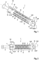
- FIG. 1 and 2 An expansion anchor 1 according to the invention is shown in perspective and in a side view.
- Figures 3 and 4 show parts of the expansion anchor 1 according to the invention, whereas in Figure 5
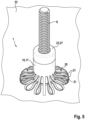
- the expansion anchor 1 according to the invention is shown in an installed state in a plasterboard 33.
- not all reference numerals are included in all figures. The reference numerals have been inserted where they are useful and necessary for understanding the function.
- the expansion anchor 1 extends along a longitudinal axis L between a front end 2 and a rear end 3.
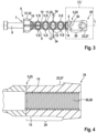
- the expansion anchor 1 has a core 4 made of plastic, which Figure 3 is shown in detail.
- the core 4 also extends along the longitudinal axis L between a front end 5 and a rear end 6.
- the front end 5 of the core 4 is oriented towards the front end 2 of the expansion anchor 1 and the rear end 6 of the core 4 corresponds to the rear end 3 of the expansion anchor 1.
- the core 4 has a circular opening 7 at its rear end 6, or at the rear end 3 of the expansion anchor 1, through which a metric screw 8 is inserted into a screw channel 9 of the core 4.
- the screw channel 9 completely penetrates the core 4 along the longitudinal axis L.
- the core 4 also has a circumferential collar 10 at the rear end 3 of the expansion anchor 1.
- Individual elliptical ring segments 11 are arranged along the longitudinal axis L. Two of the ring segments 11 together form an expansion unit 12 with an X-shaped configuration.
- the elliptical ring segments 11 are arranged along the longitudinal axis L such that the main vertices of the elliptical rings 11 each form the ends of the "X".
- the main axes of the elliptical rings 11 are each inclined to the longitudinal axis L. At the main vertices, the individual ring segments 11 are injection-molded onto one another and each have a connection point V there.
- connection points V are equidistant from one another along the longitudinal axis L and are mirror-symmetrical with respect to the longitudinal axis L.
- Each of the connection points V additionally forms an expansion zone S.
- the function of the expansion zone S will be discussed in more detail below.
- Each of the ring segments 11 has an annular opening 13, which together form the screw channel 9 for the metric screw 8.
- the predetermined buckling struts 14 border the screw channel 9 and connect the main vertices and the secondary vertices of the ring segments 11.
- An insertion lock 15 is arranged at the front end 5 of the core 4.
- the insertion lock 15 narrows the screw channel 9 at the front end 5 of the core 4 in such a way that the screw 8 cannot be pushed over the insertion lock 15.
- screw 8 To overcome the locking mechanism 15, screw 8 must be turned in the screw channel 9.
- the locking mechanism 15 corresponds to the thread of the screw 8 to be screwed in.
- a sleeve 16 made of sheet metal is arranged on the core 4 and encloses it.
- the sleeve 16 extends between a front end 18 and a rear end 19.
- the front end 18 of the sleeve 16 is oriented towards the front end 2 of the expansion anchor 1.
- the rear end 19 of the sleeve is oriented towards the rear end 3 of the expansion anchor 1.
- the sleeve 16 has a circumferential collar 17 at its front end 18, or at the front end 2 of the expansion anchor 1. Such a collar 17 is also arranged at the rear end 19.
- the two collars 17 are identical.
- the core 4 and the sleeve 16 are arranged coaxially with respect to the longitudinal axis L.
- An outer diameter of the core 4 is matched to an inner diameter of the sleeve 16 such that the sleeve 16 is longitudinally aligned with the core 4. can be pushed on until the sleeve 16 comes into contact with the collar 10 of the core 4.
- longitudinally extending buckling arms 20 and openings 22 are formed.
- the buckling arms 20 and the openings 22 are arranged alternately to one another and each have identical widths in the circumferential direction of the expansion anchor 1.
- the length of the buckling arms 20 defines a buckling area K of the expansion anchor 1. In this buckling area K, the buckling arms 20 can form buckling points 21, the formation of which will be discussed below.
- an abutment element 23 is arranged at the front end 2 of the expansion anchor 1.
- the abutment element 23 extends between a front end 24 and a rear end 25.
- a through-hole 26 extends along the longitudinal axis L through the abutment element 23.
- the abutment element 23 is designed as a bushing 27 having an internal thread 28.
- the internal thread 28 is matched to the thread of the screw 8.
- the screw 8 can be screwed into the screw channel 9 and into the abutment element 23. In this case, the insertion lock 15 must be overcome by the screwing-in movement of the screw 8.
- the bushing 27 has an insertion area 29 at its rear end 25. This is in the Figure 3 The insertion area 29 is inserted into the front end 18 of the sleeve 16.
- a positive-locking anti-twist device 30 is formed at the contact area, which contributes to the fact that, in the assembled state of the expansion anchor 1, as shown in Figure 1 shown, the core 4 is rotationally fixed to the abutment element 23.
- Two locking connections R fix the expansion anchor 1 in the Figure 1 shown state.
- a locking connection R is formed between the abutment element 23 and the front end 18 of the sleeve 16.
- the further locking connection R is formed between the rear end 19 of the sleeve 16 and the collar 10 of the core 4.
- the expansion anchor 1 is inserted in a first step into a prefabricated drill hole in a fixing base, for example a plasterboard 33, shown in Figure 5 , inserted.
- the drill hole is a through hole, it penetrates the plasterboard completely.
- the plasterboard 33 is significantly narrower than the length of the expansion anchor 1, more precisely than the extension of the bending area K in the longitudinal direction.
- the expansion anchor 1 is inserted into the drill hole until the cutting edges 32 cut into the drill hole wall and the rear end 3 of the expansion anchor 1 is flush with a surface of the front side of the plasterboard 33.
- This front side of the plasterboard 33 is a rear side of the plasterboard 33 made of Figure 5 turned away and consequently in Figure 5 not visible.
- the X-shaped ring segments 11, or rather the X-shaped expansion units 12 formed from the ring segments 11, are elastically compressed along the longitudinal axis L, whereby the core 4 is shortened and its diameter increases by approximately 20%.
- the expansion units 12 By compressing the expansion units 12, they expand it radially outwards at the connection points V (represented by the arrows of the expansion direction 34 in Figure 3 ).
- the expansion zones S formed at the connection points V press against the inner sides of the articulated arms 20.
- the articulated arms 20 are pushed radially outwards at the expansion zones S, which initiates the buckling of the articulated arms 20 at these points of the buckling area K.
- a distance between the articulated arms 20 and the core 4 increases.
- the articulated arms 20 consequently buckle and form buckling points 21, shown in Figure 5 .
- the articulated arms 20 assume the shape of a toggle lever after buckling.
- the buckling of the articulated arms 20 is completed when the articulated arms 20 return to the Figure 5 visible side of the plasterboard 33 and no further shortening of the core 4 is possible.
Landscapes
- Engineering & Computer Science (AREA)
- General Engineering & Computer Science (AREA)
- Mechanical Engineering (AREA)
- Dowels (AREA)
Applications Claiming Priority (3)
| Application Number | Priority Date | Filing Date | Title |
|---|---|---|---|
| DE102021123739 | 2021-09-14 | ||
| DE102022120712.9A DE102022120712A1 (de) | 2021-09-14 | 2022-08-17 | Spreizdübel |
| PCT/EP2022/074280 WO2023041332A1 (de) | 2021-09-14 | 2022-09-01 | Spreizdübel |
Publications (3)
| Publication Number | Publication Date |
|---|---|
| EP4402384A1 EP4402384A1 (de) | 2024-07-24 |
| EP4402384C0 EP4402384C0 (de) | 2025-07-02 |
| EP4402384B1 true EP4402384B1 (de) | 2025-07-02 |
Family
ID=83355217
Family Applications (1)
| Application Number | Title | Priority Date | Filing Date |
|---|---|---|---|
| EP22772491.1A Active EP4402384B1 (de) | 2021-09-14 | 2022-09-01 | Spreizdübel |
Country Status (3)
| Country | Link |
|---|---|
| EP (1) | EP4402384B1 (pl) |
| PL (1) | PL4402384T3 (pl) |
| WO (1) | WO2023041332A1 (pl) |
Family Cites Families (3)
| Publication number | Priority date | Publication date | Assignee | Title |
|---|---|---|---|---|
| CH537532A (de) * | 1969-05-30 | 1973-05-31 | Aackersberg Mortensen | Aufweitbare Befestigungs- oder Verankerungseinrichtung |
| DK125488B (da) * | 1969-05-30 | 1973-02-26 | L Mortensen | Rørformet ekspansionsdybellegeme eller lignende befæstigelsesorgan og fremgangsmåde til fremstilling af dette. |
| IT201700124235A1 (it) | 2017-10-31 | 2019-05-01 | Illinois Tool Works | Tassello ad espansione |
-
2022
- 2022-09-01 WO PCT/EP2022/074280 patent/WO2023041332A1/de not_active Ceased
- 2022-09-01 EP EP22772491.1A patent/EP4402384B1/de active Active
- 2022-09-01 PL PL22772491.1T patent/PL4402384T3/pl unknown
Also Published As
| Publication number | Publication date |
|---|---|
| EP4402384C0 (de) | 2025-07-02 |
| PL4402384T3 (pl) | 2026-02-23 |
| EP4402384A1 (de) | 2024-07-24 |
| WO2023041332A1 (de) | 2023-03-23 |
Similar Documents
| Publication | Publication Date | Title |
|---|---|---|
| EP1510701B1 (de) | Vorrichtung zum Verbinden von Bauteilen mit Blindnietbefestigung | |
| EP3060816B1 (de) | Spreizanker mit bereichsweise hochfester spreizhülse | |
| EP2533962B1 (de) | Spreizdübel | |
| EP3098461B1 (de) | Rastbolzen | |
| EP2792892B1 (de) | Blindnietmutter | |
| EP0521490B1 (de) | Anordnung aus zwei teleskopisch miteinander verbundenen Bauelementen | |
| EP3274596A1 (de) | Spreizanker | |
| EP3894711B1 (de) | Spreizdübel | |
| DE10302984B3 (de) | Säuleneinheit | |
| EP4402384B1 (de) | Spreizdübel | |
| DE102022120712A1 (de) | Spreizdübel | |
| EP2108851A2 (de) | Spreizdübel | |
| EP0118006A1 (de) | Schlaganker | |
| WO2008058621A1 (de) | Spreizdübel mit in axialer richtung nachgiebiger hülse | |
| DE102014224561B3 (de) | Spannfutter | |
| EP1412117B1 (de) | Distanzelement für eine spannzange und spannzange | |
| EP4402383B1 (de) | Selbstschneidender hinterschnittanker | |
| EP2682543A2 (de) | Beschlaganordnung | |
| EP0717204A1 (de) | Sicherheitsbolzen, der in Durchgangslöcher von Bauteilen bis zu einem Anschlag einschiebbar ist | |
| EP2612040B1 (de) | Spreizdübel | |
| DE202020102064U1 (de) | Spannbare elektrische Heizvorrichtung | |
| DE20306091U1 (de) | Türdichtungsvorrichtung | |
| DE102005018485A1 (de) | Dübel zur Verankerung in Vollbaustoffen | |
| EP2905391A1 (de) | Dübel, Setzwerkzeug und Verfahren zur Befestigung von Dämmstoffen | |
| EP4421332B1 (de) | Spreizdübel aus kunststoff |
Legal Events
| Date | Code | Title | Description |
|---|---|---|---|
| STAA | Information on the status of an ep patent application or granted ep patent |
Free format text: STATUS: UNKNOWN |
|
| STAA | Information on the status of an ep patent application or granted ep patent |
Free format text: STATUS: THE INTERNATIONAL PUBLICATION HAS BEEN MADE |
|
| PUAI | Public reference made under article 153(3) epc to a published international application that has entered the european phase |
Free format text: ORIGINAL CODE: 0009012 |
|
| STAA | Information on the status of an ep patent application or granted ep patent |
Free format text: STATUS: REQUEST FOR EXAMINATION WAS MADE |
|
| 17P | Request for examination filed |
Effective date: 20240301 |
|
| AK | Designated contracting states |
Kind code of ref document: A1 Designated state(s): AL AT BE BG CH CY CZ DE DK EE ES FI FR GB GR HR HU IE IS IT LI LT LU LV MC MK MT NL NO PL PT RO RS SE SI SK SM TR |
|
| DAV | Request for validation of the european patent (deleted) | ||
| DAX | Request for extension of the european patent (deleted) | ||
| GRAP | Despatch of communication of intention to grant a patent |
Free format text: ORIGINAL CODE: EPIDOSNIGR1 |
|
| STAA | Information on the status of an ep patent application or granted ep patent |
Free format text: STATUS: GRANT OF PATENT IS INTENDED |
|
| INTG | Intention to grant announced |
Effective date: 20250326 |
|
| GRAS | Grant fee paid |
Free format text: ORIGINAL CODE: EPIDOSNIGR3 |
|
| GRAA | (expected) grant |
Free format text: ORIGINAL CODE: 0009210 |
|
| STAA | Information on the status of an ep patent application or granted ep patent |
Free format text: STATUS: THE PATENT HAS BEEN GRANTED |
|
| AK | Designated contracting states |
Kind code of ref document: B1 Designated state(s): AL AT BE BG CH CY CZ DE DK EE ES FI FR GB GR HR HU IE IS IT LI LT LU LV MC MK MT NL NO PL PT RO RS SE SI SK SM TR |
|
| REG | Reference to a national code |
Ref country code: GB Ref legal event code: FG4D Free format text: NOT ENGLISH |
|
| REG | Reference to a national code |
Ref country code: CH Ref legal event code: EP |
|
| REG | Reference to a national code |
Ref country code: DE Ref legal event code: R096 Ref document number: 502022004545 Country of ref document: DE |
|
| REG | Reference to a national code |
Ref country code: IE Ref legal event code: FG4D Free format text: LANGUAGE OF EP DOCUMENT: GERMAN |
|
| U01 | Request for unitary effect filed |
Effective date: 20250702 |
|
| U07 | Unitary effect registered |
Designated state(s): AT BE BG DE DK EE FI FR IT LT LU LV MT NL PT RO SE SI Effective date: 20250709 |
|
| U20 | Renewal fee for the european patent with unitary effect paid |
Year of fee payment: 4 Effective date: 20250805 |
|
| PG25 | Lapsed in a contracting state [announced via postgrant information from national office to epo] |
Ref country code: IS Free format text: LAPSE BECAUSE OF FAILURE TO SUBMIT A TRANSLATION OF THE DESCRIPTION OR TO PAY THE FEE WITHIN THE PRESCRIBED TIME-LIMIT Effective date: 20251102 |
|
| PG25 | Lapsed in a contracting state [announced via postgrant information from national office to epo] |
Ref country code: NO Free format text: LAPSE BECAUSE OF FAILURE TO SUBMIT A TRANSLATION OF THE DESCRIPTION OR TO PAY THE FEE WITHIN THE PRESCRIBED TIME-LIMIT Effective date: 20251002 |
|
| PG25 | Lapsed in a contracting state [announced via postgrant information from national office to epo] |
Ref country code: HR Free format text: LAPSE BECAUSE OF FAILURE TO SUBMIT A TRANSLATION OF THE DESCRIPTION OR TO PAY THE FEE WITHIN THE PRESCRIBED TIME-LIMIT Effective date: 20250702 |
|
| PG25 | Lapsed in a contracting state [announced via postgrant information from national office to epo] |
Ref country code: GR Free format text: LAPSE BECAUSE OF FAILURE TO SUBMIT A TRANSLATION OF THE DESCRIPTION OR TO PAY THE FEE WITHIN THE PRESCRIBED TIME-LIMIT Effective date: 20251003 |
|
| PG25 | Lapsed in a contracting state [announced via postgrant information from national office to epo] |
Ref country code: CZ Free format text: LAPSE BECAUSE OF FAILURE TO SUBMIT A TRANSLATION OF THE DESCRIPTION OR TO PAY THE FEE WITHIN THE PRESCRIBED TIME-LIMIT Effective date: 20250702 |
|
| PG25 | Lapsed in a contracting state [announced via postgrant information from national office to epo] |
Ref country code: RS Free format text: LAPSE BECAUSE OF FAILURE TO SUBMIT A TRANSLATION OF THE DESCRIPTION OR TO PAY THE FEE WITHIN THE PRESCRIBED TIME-LIMIT Effective date: 20251002 |
|
| PG25 | Lapsed in a contracting state [announced via postgrant information from national office to epo] |
Ref country code: ES Free format text: LAPSE BECAUSE OF FAILURE TO SUBMIT A TRANSLATION OF THE DESCRIPTION OR TO PAY THE FEE WITHIN THE PRESCRIBED TIME-LIMIT Effective date: 20250702 |