EP4402311B1 - Gestrickte komponenten und artikel für verbesserte ballkontrolle und haltbarkeit - Google Patents
Gestrickte komponenten und artikel für verbesserte ballkontrolle und haltbarkeit Download PDFInfo
- Publication number
- EP4402311B1 EP4402311B1 EP21787253.0A EP21787253A EP4402311B1 EP 4402311 B1 EP4402311 B1 EP 4402311B1 EP 21787253 A EP21787253 A EP 21787253A EP 4402311 B1 EP4402311 B1 EP 4402311B1
- Authority
- EP
- European Patent Office
- Prior art keywords
- areas
- yarn
- area
- knitted component
- friction
- Prior art date
- Legal status (The legal status is an assumption and is not a legal conclusion. Google has not performed a legal analysis and makes no representation as to the accuracy of the status listed.)
- Active
Links
Images


Classifications
-
- A—HUMAN NECESSITIES
- A43—FOOTWEAR
- A43B—CHARACTERISTIC FEATURES OF FOOTWEAR; PARTS OF FOOTWEAR
- A43B1/00—Footwear characterised by the material
- A43B1/02—Footwear characterised by the material made of fibres or fabrics made therefrom
- A43B1/028—Synthetic or artificial fibres
-
- A—HUMAN NECESSITIES
- A43—FOOTWEAR
- A43B—CHARACTERISTIC FEATURES OF FOOTWEAR; PARTS OF FOOTWEAR
- A43B1/00—Footwear characterised by the material
- A43B1/02—Footwear characterised by the material made of fibres or fabrics made therefrom
- A43B1/04—Footwear characterised by the material made of fibres or fabrics made therefrom braided, knotted, knitted or crocheted
-
- A—HUMAN NECESSITIES
- A43—FOOTWEAR
- A43B—CHARACTERISTIC FEATURES OF FOOTWEAR; PARTS OF FOOTWEAR
- A43B23/00—Uppers; Boot legs; Stiffeners; Other single parts of footwear
- A43B23/02—Uppers; Boot legs
- A43B23/0205—Uppers; Boot legs characterised by the material
-
- A—HUMAN NECESSITIES
- A43—FOOTWEAR
- A43B—CHARACTERISTIC FEATURES OF FOOTWEAR; PARTS OF FOOTWEAR
- A43B23/00—Uppers; Boot legs; Stiffeners; Other single parts of footwear
- A43B23/02—Uppers; Boot legs
- A43B23/0205—Uppers; Boot legs characterised by the material
- A43B23/0215—Plastics or artificial leather
-
- A—HUMAN NECESSITIES
- A43—FOOTWEAR
- A43B—CHARACTERISTIC FEATURES OF FOOTWEAR; PARTS OF FOOTWEAR
- A43B23/00—Uppers; Boot legs; Stiffeners; Other single parts of footwear
- A43B23/02—Uppers; Boot legs
- A43B23/0245—Uppers; Boot legs characterised by the constructive form
- A43B23/025—Uppers; Boot legs characterised by the constructive form assembled by stitching
-
- D—TEXTILES; PAPER
- D04—BRAIDING; LACE-MAKING; KNITTING; TRIMMINGS; NON-WOVEN FABRICS
- D04B—KNITTING
- D04B1/00—Weft knitting processes for the production of fabrics or articles not dependent on the use of particular machines; Fabrics or articles defined by such processes
- D04B1/10—Patterned fabrics or articles
- D04B1/102—Patterned fabrics or articles with stitch pattern
-
- D—TEXTILES; PAPER
- D04—BRAIDING; LACE-MAKING; KNITTING; TRIMMINGS; NON-WOVEN FABRICS
- D04B—KNITTING
- D04B1/00—Weft knitting processes for the production of fabrics or articles not dependent on the use of particular machines; Fabrics or articles defined by such processes
- D04B1/14—Other fabrics or articles characterised primarily by the use of particular thread materials
- D04B1/16—Other fabrics or articles characterised primarily by the use of particular thread materials synthetic threads
-
- D—TEXTILES; PAPER
- D04—BRAIDING; LACE-MAKING; KNITTING; TRIMMINGS; NON-WOVEN FABRICS
- D04B—KNITTING
- D04B1/00—Weft knitting processes for the production of fabrics or articles not dependent on the use of particular machines; Fabrics or articles defined by such processes
- D04B1/22—Weft knitting processes for the production of fabrics or articles not dependent on the use of particular machines; Fabrics or articles defined by such processes specially adapted for knitting goods of particular configuration
- D04B1/24—Weft knitting processes for the production of fabrics or articles not dependent on the use of particular machines; Fabrics or articles defined by such processes specially adapted for knitting goods of particular configuration wearing apparel
-
- D—TEXTILES; PAPER
- D10—INDEXING SCHEME ASSOCIATED WITH SUBLASSES OF SECTION D, RELATING TO TEXTILES
- D10B—INDEXING SCHEME ASSOCIATED WITH SUBLASSES OF SECTION D, RELATING TO TEXTILES
- D10B2401/00—Physical properties
- D10B2401/04—Heat-responsive characteristics
- D10B2401/041—Heat-responsive characteristics thermoplastic; thermosetting
-
- D—TEXTILES; PAPER
- D10—INDEXING SCHEME ASSOCIATED WITH SUBLASSES OF SECTION D, RELATING TO TEXTILES
- D10B—INDEXING SCHEME ASSOCIATED WITH SUBLASSES OF SECTION D, RELATING TO TEXTILES
- D10B2403/00—Details of fabric structure established in the fabric forming process
- D10B2403/01—Surface features
-
- D—TEXTILES; PAPER
- D10—INDEXING SCHEME ASSOCIATED WITH SUBLASSES OF SECTION D, RELATING TO TEXTILES
- D10B—INDEXING SCHEME ASSOCIATED WITH SUBLASSES OF SECTION D, RELATING TO TEXTILES
- D10B2501/00—Wearing apparel
- D10B2501/04—Outerwear; Protective garments
- D10B2501/043—Footwear
-
- D—TEXTILES; PAPER
- D10—INDEXING SCHEME ASSOCIATED WITH SUBLASSES OF SECTION D, RELATING TO TEXTILES
- D10B—INDEXING SCHEME ASSOCIATED WITH SUBLASSES OF SECTION D, RELATING TO TEXTILES
- D10B2505/00—Industrial
- D10B2505/08—Upholstery, mattresses
-
- D—TEXTILES; PAPER
- D10—INDEXING SCHEME ASSOCIATED WITH SUBLASSES OF SECTION D, RELATING TO TEXTILES
- D10B—INDEXING SCHEME ASSOCIATED WITH SUBLASSES OF SECTION D, RELATING TO TEXTILES
- D10B2507/00—Sport; Military
Definitions
- the claimed invention is directed to a knitted component, a knitted article of footwear upper and a method of manufacturing a knitted component.
- Document WO 2018/089501 A1 describes an article with heat-treatable thermoplastic yarn.
- the article may include knit structures that at least partially affect rigidity in a zone that includes thermoplastic yarn.
- the article may include knit structures that at least partially affect elasticity in a zone that includes thermoplastic yarn.
- a variety of articles, including footwear, are formed of textiles, which are often formed by interlooping (e.g., knitting) a yarn or plurality of yarns.
- an upper for an article of footwear may be formed from a knitted textile.
- non-textile components may be added and secured (e.g., adhered, stitched) to the textile.
- polyurethanes e.g., crosslinked polyurethanes
- synthetic leather textiles e.g., laminate film layers
- laminate film layers can be used as durable covering layers.
- any additional layer, even a film reduces the ability of the article to conform to a wearer and provide proprioceptive feedback, which can be particularly important for articles in certain sporting activities.
- an article of footwear for football for example, it may be important for a wearer to be able to feel the ball through the textile as well as to have certain levels of traction or grip for ball control and handling. At the same time, too much grip in the footwear may interfere with the wearer's ability to perform quick touches and ball handling maneuvers. Further, as different parts of the footwear may be utilized for different types of moves, a textile for an upper with different characteristics (e.g., patterns) in different portions may be desired.
- grip or traction for object (e.g., ball) control is achieved with alternating patterns of first areas and second areas having varying grip. These alternating patterns assist in fine tuning ball control such that a desirable amount of grip is achieved.
- the textiles described herein, such as knitted components or footwear uppers include alternating patterns of first areas with a first coefficient of friction and second areas with a second coefficient of friction that is different from or lower than the first coefficient of friction. This alternating between a first area and the second area on a surface of a footwear upper achieves an interaction between the footwear upper and the object, such as a ball, that may enhance a sense of control by the wearer of the footwear upper.
- a surface of a footwear upper having alternating patterns of the first areas and the second areas in which the first areas are 40% to 80% of a total surface area of an external-facing surface of a portion (e.g., a ball-contacting region) of the footwear upper is effective to achieve a potentially enhanced sense of control by the wearer of the footwear upper.
- Thermoplastic elastomers have been identified which can be incorporated into polymeric compositions that provide levels of abrasion resistance, traction (which may also be referred to as grip), or both, making them suitable for use in articles where abrasion resistance or traction are desirable, such as articles of apparel, footwear and sporting equipment.
- the level of abrasion resistance, traction, or both provided by these polymeric compositions are equivalent to or better than standard vulcanized rubber compositions used in the manufacture of footwear, apparel and sporting equipment.
- Unlike vulcanized rubber due to the thermoplastic nature of these polymeric compositions, and their properties in the solid and molten state, it is possible to readily form them into coated yarns that have suitable properties for use in industrial scale knitting or weaving equipment.
- these properties result in yarns that can readily be incorporated into various articles including textiles using conventional manufacturing processes such as knitting and weaving, as well as industrial scale processes for making non-woven textiles. Also, unlike vulcanized rubber, these textiles and articles into which these textiles are incorporated can then, in turn, be thermoformed in a manner that reflows the polymeric composition of the coated yarns and creates an abrasion resistant or high grip surface on the textile or article under conditions that do not damage other components of the textile or article, such as, for example, other yarns, other textiles, foams, molded resin components, etc.
- a knitted component includes a first yarn having a first core yarn (also referred to herein as a "core”) and a first coating (also referred to herein as a "coating") that may comprise a thermoplastic elastomer.
- the thermoplastic composition may comprise one or more thermoplastic elastomers at least partially surrounding the first core yarn.
- the knitted component further includes a second yarn that is different from the first yarn.
- first areas are formed of the first yarn while second areas are formed of the second yarn. Due at least in part to the material of the first yarn and the second yarn, the first areas and the second areas have different coefficients of friction relative to a common material. According to the claimed invention, the first areas have a higher coefficient of friction than the second areas to provide increased grip in the first areas relative to the second areas. For example, the first areas may have a higher coefficient of friction with a ball surface than a coefficient of friction between the second area and the same ball surface.
- a second coefficient of friction of the second areas is within a range from about 10% to about 75% less than a first coefficient of friction of the first areas.
- the first and second areas form an alternating pattern where the first areas make up 40% to 80% of the total surface area of the first surface (e.g., a ball-contacting portion of a footwear upper), which provide an improved level of grip over the knitted component.
- a further aspect of the claimed invention relates to a knitted article of footwear upper as defined in claim 9.
- the alternating pattern of the first and second areas may improve ball control and handling as well as provide abrasion resistance.
- the alternating pattern includes a pattern of concentric shapes (e.g., curvilinear boundaries between first areas and second areas) on a medial side of the upper.
- first and second areas may form a different alternating pattern of stripes (e.g., linear boundaries between first areas and second areas).
- the stripes in an example, generally extend from a biteline to a throat, such as on a lateral side of the upper. Whereas the concentric shape patterns of the first and second areas on the medial side may be desired for ball passing, receiving, and kicking movements, a more linear pattern on the lateral side may be desired for dragging movements or nudging of the ball.
- the knitted component may be thermoformed such that the first coating flows and occupies at least a portion of spaces between courses of the first yarn or courses of the first core yarn.
- This arrangement can advantageously integrate 360-degree ball control directly into the knitted component without the need for laminated skins, streamlining the surface into a single functional layer.
- this single functional layer can help bring the wearer closer to the ball by removing a layer therefrom, which thereby increases proprioceptive feedback to the wearer and further improves ball control.
- not including a laminated skin improves manufacturing efficiency by reducing post-knitting processes.
- a further aspect of the claimed invention relates to a method of manufacturing a knitted component as defined in the appended independent claim.
- certain aspects are directed to one or more knitted components or thermoformed knitted components.
- such knitted components or thermoformed knitted components form at least a portion of an article of sporting equipment or article of wear, including articles of footwear.
- One aspect of the claimed invention is directed to an upper for an article of footwear formed of a knitted component according to claim 1.
- Articles of footwear conventionally include an upper and a sole structure. The upper is secured to the sole structure and forms a void within the article of footwear for comfortably and securely receiving a foot.
- the term "upper” refers to a footwear component that extends over the instep and toe areas of the foot, along the medial and lateral sides of the foot, and around the heel area of the foot to form a void for receiving a wearer's foot.
- Illustrative, non-limiting examples of uppers may include uppers incorporated into a basketball shoe, a biking shoe, a cross-training shoe, a global football (soccer) shoe, an American football shoe, a bowling shoe, a golf shoe, a hiking shoe, a ski or snowboarding boot, a tennis shoe, a running shoe, and a walking shoe.
- the upper may also be incorporated into a non-athletic shoe, such as a dress shoe, a loafer, and a sandal. Accordingly, the concepts disclosed with respect to articles of footwear apply to a wide variety of footwear types.
- 1A and 1B generally may include a ground-facing outsole area 110, an ankle collar area 112, a lateral midfoot area 114a, a medial midfoot area 114b, a forefoot area 116, and a heel area 118.
- the article of footwear 100 may include a plurality of eyestays 120, a tongue 124, and a throat area 126. As shown in FIGS. 1A and 1B , the article of footwear 100, is intended to be used with a right foot; however, it should be understood that the following discussion may also apply to a mirror image of the article of footwear 100 that is intended for use with a left foot.
- the outsole 109 may be secured to a lower surface of the midsole 107 and may comprise a wear-resistant elastomeric material such as a natural or synthetic rubber material.
- the outsole 109 may be textured to impart traction or can include one or more traction elements.
- the traction elements may be separate elements affixed to the outsole 109 or may be integrally formed with the outsole 109.
- the first core yarn may be coated by any method known in the art.
- the polymeric compositions for the first coating disclosed herein are suitable for manufacturing by pultrusion and/or pulling the yarns through baths of liquid polymeric materials.
- sufficient coating material is provided on the first yarn such that, when knit alone or with one or more other yarns in various configurations and subsequently thermoformed and allowed to re-flow and re-solidify, the coating material (e.g., polymeric composition comprising a thermoplastic elastomer) forms a structure with an adequate concentration of the coating material on one or more surfaces, and/or within the first core yarn, depending upon the placement of the first yarn within the knit structure.
- the first coating of the first yarn comprises a polymeric composition that comprises a thermoplastic composition that comprises a thermoplastic elastomer. While it is possible to extrude a polymeric composition that is a thermoplastic elastomeric composition and form fibers, filaments, yarns or films directly from the polymeric composition, due to its elastomeric properties, these forms of the polymeric composition will have high levels of stretch and heat shrinkage. This means the fibers, filaments, yarns or films may tend to stretch around machine guides, rather than slide past them, and may tend to shrink at the temperatures commonly encountered in industrial-scale knitting and weaving equipment.
- this first yarn may also allow for new methods of manufacturing that will allow for different placements of the polymeric composition within textiles and articles comprising the textiles at greater levels of specificity in terms of both location and amount as compared to conventional manufacturing processes.
- thermoplastic nature of the polymeric composition makes it possible to melt the composition and use it to coat the first core yarn when the melting temperature of the polymeric composition is sufficiently lower than the deformation temperature of the first core yarn, as well as to subsequently thermoform the knitted component 130 to create a thermoformed network comprising both the first core yarn and the re-flowed and re-solidified polymeric composition consolidating the first core yarn.
- the thermoplastic elastomer(s) of the polymeric composition of the coating have glass transition temperature(s) below minus 20 degrees Celsius, which allows the thermoplastic elastomer(s) present in the polymeric composition to be in their "rubbery" state, even when the knitted component 130 is used in cold environments.
- the melting temperature of polymeric composition of the coating is at least 100 degrees Celsius, which may ensure the polymeric composition will not melt when the knitted component 130 is shipped or stored under hot conditions. In another aspect, the melting temperature of polymeric composition of the coating is at least 130 degrees Celsius, which ensures the polymeric composition will not melt when the knitted component 130 is subjected to conditions often encountered by textiles during the manufacturing processes for articles of footwear, apparel or sporting equipment, such as steaming processes. In another aspect, the melting temperature of polymeric composition of the coating is at less than 170 degrees Celsius, which ensures the knitted component 130 may be thermoformed at temperatures that do not negatively impact other textiles or components that may form part of the upper 102.
- the enthalpy of melting of the thermoplastic elastomer(s) of the polymeric composition of the coating may be less than about 30 Joules per gram or 25 Joules per gram, which means that, during the thermoforming process, less heat and a shorter heating time is required to fully melt the polymeric composition and achieve good flow of the molten polymeric composition to better consolidate the network of yarns in the knitted component 130.
- the recrystallization temperature of thermoplastic elastomer(s) of the polymeric composition of the coating may be above 60 degrees Celsius, or above 95 degrees Celsius, which may promote rapid re-solidification of the polymeric composition after thermoforming, which may reduce the amount of time required to cool the textile after thermoforming and may avoid the need to provide active cooling of the textile, thereby reducing cycle time and reducing energy consumption.
- the knitted component 130 also includes the second yarn in addition to the first yarn (i.e., the coated yarn), the thermoformed network of yarns (i.e., the core yarn from the first yarn and the second yarn) are consolidated by the re-flowed and re-solidified polymeric composition.
- the presence of the re-flowed and re-solidified polymeric composition may serve one or more functions within the thermoformed textile, such as controlling the level of stretch within the entire knitted component 130 or just within a region thereof, forming a skin having high abrasion-resistance and/or traction across an entire surface of the knitted component 130 or just within a region thereof, improving water resistance of an entire surface of the knitted component 130 or just within a region thereof, or bonding all of the knitted component 130 or just a region thereof to a substrate.
- the coating of the first yarn, when thermoformed, may form a skin on a surface of the knitted component 130.
- the coating of the first yarn, when thermoformed may act as a bonding agent, either to bond yarns together within the knitted component 130, or to bond other elements to a surface of the knitted component 130.
- the use of the thermoformed knitted component 130 described herein may replace one or more of the separate elements conventionally added to increase abrasion resistance or create traction, reducing waste and simplifying manufacturing processes while improving recyclability of the articles.
- thermoformed network of the thermoformed textile may form an externally-facing surface of an upper, such as the first surface 105 of the knitted component 130 in FIGS. 1A and 1B .
- the thermoformed network created by thermoforming the textiles has superior properties for ball contact, in that the properties of the thermoformed network may be equal to or superior to those of kangaroo skin leather in terms of the spin rate imparted to the ball by the upper when kicking the ball.
- properties of the thermoformed network may be equal to or superior to those of kangaroo skin leather in terms of the spin rate imparted to the ball by the upper when kicking the ball.
- Durometer Hardness Shore A
- Uppers comprising the textiles described herein have also been found to be equivalent to or superior to those of synthetic leather or knit uppers coated with a skin in terms of traction under wet and dry conditions.
- the second yarn may be integrally knit with the first yarn to form the thermoformed network in at least some regions of the knitted component 130.
- the knitted component 130 has a first surface 105 forming an exterior-facing surface of the upper 102 as shown in FIGS. 1A and 1B .
- the knitted component 130 also includes an opposite second surface, which may form the inner-facing surface of the upper 102 and is not visible in FIGS. 1A and 1B .
- the first surface 105 includes a plurality of first areas and a plurality of second areas (e.g., first areas 108 and second areas 106). To distinguish between these areas in FIGS. 1A and 1B , first areas 104 are depicted with a lighter shading than the second area 106. However, it should be understood that the shading should not necessarily limit the relative coloring of these areas 104 and 106.
- the first areas 108 on the first surface 105 comprise the first yarn and the second areas 106 on the first surface 105 comprise the second yarn.
- the second areas 106 entirely or substantially exclude the first yarn.
- the first areas 108 entirely or substantially exclude the second yarn.
- the first areas 108 may have trace amounts of the first yarn and/or the second areas 106 may have trace amounts of the second yarn without departing from the technology described herein. "Trace amounts" is defined herein as approximately less than 10% by weight of a particular yarn (for example, less than 10% by weight of the first yarn or less than 10% by weight of the second yarn).
- the first yarn has a first core yarn and a first coating that may comprise a thermoplastic polymeric composition.
- the thermoplastic polymeric composition may comprise one or more thermoplastic elastomers at least partially surrounding the first core yarn.
- the second yarn may include filaments of a thermoplastic material comprising a polyester. However, the second yarn does not include the thermoplastic polymeric composition that makes up the first coating, in an example.
- first areas 108 have a different coefficient of friction than the second areas 106.
- a common testing standard is applied to both the first areas and the second areas. For example, a sample with just the first areas can be tested using ASTM D1894 to determine the static or dynamic coefficient of friction of the first areas described herein. Likewise, a sample with just the second areas can be tested using ASTM D1894 to determine the static or dynamic coefficient of friction of the second areas described herein.
- ASTM D1894 to determine the static or dynamic coefficient of friction of the second areas described herein.
- modified versions of the ASTM D1894 or other tests can be used without departing from the scope of the technology herein, as long as a common testing standard is applied for both the first areas and the second areas.
- the coefficient of friction (wet or dry) for the second areas 106 is within a range from about 10% to about 75% less than the coefficient of friction (wet or dry) of the first areas 108, particularly within a range from about 15% to about 60% less than the coefficient of friction (wet or dry) for the first areas 108, or further particularly within a range from about 20% to about 50% less than the coefficient of friction (wet or dry) for the first areas 108.
- the first and second areas 108 and 106 may also have other differing physical properties.
- the first yarn or the first coating of the first yarn and the second yarn may differ based on at least one of a hue, a value, and chroma of their colors.
- first areas 108 and the second areas 106 may differ based on at least one of a hue, a value, and a chroma of their colors.
- Other visual differences between the first yarn and the second yarn and the first areas 108 and the second areas 106 may be used without departing from the scope of the technology herein. However, in some aspects, visual differences between the first and second areas 108 and 106 may be minimal or nonexistent, while differences in other physical characteristics remain.
- the size and dimensions of the first areas 108 may be similar or different from the size and dimensions of the second areas 106, however, the ratio of the total surface area of the first areas 108 to the second areas 106 depends upon the amount of grip and/or ball control desired.
- the ratio of the total surface area of the first areas 108 to the second areas 106 may be greater in instances where more grip and/or ball control is desired, whereas the ratio of the total surface area of the first areas 108 to the second areas 106 may be less in instances where less grip is desired.
- the first areas 108 make up a percentage of the total surface area within a region of the first surface 105 of the knitted component 103 that is within a range from about 40% to about 80%, particularly within a range from about 50% to about 70%, and/or further particularly within a range from about 55% to about 65%.
- the ranges provided herein are inclusive of the values on either end of the range.
- the range of 40% to 80% is inclusive of 40% and 80%.
- the second areas 106 may form a percentage of the total surface area of the first surface 105 of the knitted component 103 that is within a range from about 20% to about 60%, within a range from about 30% to about 50%, and/or within a range from about 55% to about 65%.
- the lateral side of the upper 102 depicted in FIG. 1A includes the first areas 108 and the second areas 106 arranged in an alternating striped pattern extending generally vertically when the upper 102 is in an as-worn configuration with the sole structure 104 contacting a ground surface.
- the first areas 108 and the second areas 106 may generally extend from a bottom edge 150 of the knitted component 130 towards the throat area 126. At least part of the bottom edge 150 of the knitted component 130 may align with the biteline 152 where the upper 102 joins the sole structure 104.
- the stripes formed by alternating the first areas 108 and the second areas 106 on the lateral side may extend in the lateral midfoot area 114a as well as in the forefoot area 116. Further, in aspects in which the knitted component 130 extends to the heel area 118, the stripes may also extend in the heel area 118.
- a stripe is an example of an alternating pattern that includes linear boundaries between first areas 108 and second areas 106.
- At least some of the stripes may have a zigzag configuration, a wavy-line configuration, a parallel line configuration, and/or any other striped configuration, such as stripes that follow a curvature of the knitted component 130. Additionally or alternatively, at least portions of the stripes may have varying widths along a length thereof. For example, the varying widths may range from as narrow as 3 millimeters to as wide as one centimeter. Any number of stripes formed via the alternating of the first areas 108 and the second areas 106 may be included on the knitted component 130.
- the first areas 108 form between 10 and 40 stripes on the first surface 105 of the knitted component 130, while in other aspects, the first areas 108 form between 25 and 35 stripes on first surface 105 of the knitted component 130.
- the number and configuration of the stripes depends upon the amount of grip and/or ball control desired and, in turn, the ratio of total surface area of the first areas 108 to the second areas 106 as discussed above.
- the first areas 108 and the second areas 106 alternate to form a concentric pattern of shapes or, in other words, a "swirl" or "whirl” pattern.
- the concentric pattern of the first areas 108 and the second areas 106 includes irregularly shaped circles. Swirl or whirl patterns are examples of alternating patterns having curvilinear boundaries between the first areas 108 and the second areas 106.
- the concentric shapes may be triangular, circular, ovular, parallelograms, pentagons, hexagons, star-shaped, heart-shaped, a combination thereof, or any combination of concentric shapes without departing from the scope of the technology described herein.
- the pattern is concentric in that at least the first areas 108 and the second areas 108 that are part of the concentric pattern are coaxial and share a common center.
- the center of the concentric pattern in FIG. 1B is positioned within the medial midfoot area 114b and helps to impart spin on a ball, such as a football, when kicked.
- the second areas 106 may cover more of the first surface 105 than is covered by the first areas 108 in this region of the upper.
- the concentric pattern within the medial midfoot area 114b may be nestled between a series of stripes formed by alternating additional first areas 108 and additional second areas 106.
- One or more of these stripes adjacent to the concentric pattern may have a curvature or angle that corresponds to a curvature or angle of the shapes forming the concentric pattern, as shown in FIG. 1B .
- FIG. 1C depicts another aspect of the alternating pattern of the first areas 108 and the second areas 106 on a medial side of the upper 102.
- the first areas 108 and the second areas 106 may still generally form a concentric pattern of shapes, but the shapes may be formed of broken lines of varying length and curvature that cooperatively form the shape within the concentric pattern.
- first areas 108 and second areas 106 on the lateral and medial sides of the upper 102 reflects different types of movement that may be executed in certain activities.
- the medial side of the foot is often used for passing, receiving, and/or kicking a ball while the lateral side of the foot is used for other ball manipulation, such as dragging or nudging of the ball.
- different ratios and patterns of the first areas 108 and the second areas 106 may provide different grip patterns suited for particular activities.
- the knitted component 130 includes a third yarn comprising an elastane or an elastic polyurethane material.
- the third yarn is knit on the second surface of the knitted component 130 opposite the first surface 105.
- the third yarn may be knit on the second surface in areas opposite the first areas 108 and second areas 106 on the first surface 105.
- the third yarn is knit only on one needle bed, such as a back needle bed, such that the third yarn is only on the second surface and is absent from the first surface 105.
- FIG. 2B depicts the portion 200 after being exposed to a thermoforming process.
- the first yarn 210 that comprises a thermoplastic polymeric composition as described herein was thermoformed from a solid yarn structure into a melted yarn component 212, with a core yarn 214 of the first yarn 210 still remaining in its interlooped configuration.
- the heating step of the thermoforming process at least partly causes the coating in the first yarn 210 to melt and flow and then subsequently solidify by the completion of the thermoforming process into the melted yarn component 212.
- This melted yarn component 212 is the coating surrounding the core yarn 214 of the first yarn 210 after that coating is melted, flowed, and resolidifed.
- the melted yarn component 212 in FIG. 2B is depicted as contacting and at least partially surrounding the core yarn 214 of the first yarn 210 and contacting and at least partially surrounding a portion of the second yarn 208, at least on the portions of the first course 202 and the second course 204 that interloop with or are proximate to the third course 206 forming a network.
- the melted yarn component 212 may be thermoformed to spread to a greater extent or a lesser extent on the external-facing surface of the textile than depicted in FIG. 2B without departing from the technology described herein.
- the areas with the melted yarn component 212 created from thermoforming may have increased abrasion resistance and increased water resistance properties compared to areas without a thermoformed melted yarn component 212. Further, because these properties are provided through the knit structure instead of being applied as an additional layer or film, the portion 200 of the knitted component may remain relatively thin and flexible. As such, the melted yarn component 212 may be utilized in high-flex areas of an upper, such as the area between the throat and the forefoot region, without premature wear or breakage.
- FIGS. 2A and 2B are merely examples of knitting and thermoforming as described herein.
- Other knit patterns with any plurality of adjacent rows, and/or any plurality of adjacent loops, of predominately the first yarn 210 or of predominately the second yarn 208 may be used for forming one of the first areas (such as first areas 108 of FIGS. 1A-1C ) or the second areas (such as second areas 106 of FIGS. 1A-1C ) on a surface of a knitted component as described herein without departing from the scope of the technology herein.
- portion 200 is shown with only a single knit layer.
- the disclosure may include a knitted component with a double knit structure formed using needles on two needle beds.
- the first yarn 210 may be knit on a front needle bed to form the loops in the third course 206 in FIG. 2A , which may form the first surface of the knitted component, and in another course, such as a course knit simultaneously with the first course 202, the first yarn 210 may be knit on the back needle bed to form at least part of the second surface of the knitted component.
- the second yarn 208 may be knit on a front needle bed to form the loops in the first course 202 and the second course 204 in FIG.
- the second yarn 208 may be knit on the back needle bed to form at least part of the second surface of the knitted component.
- the first yarn 210 and/or the second yarn 208 may be moved back and forth between front and back needle beds within a single course.
- loops forming courses for the second surface may be formed from a third yarn having an elastane or an elastic polyurethane material.
- the melted yarn component 212 may extend between the knit layers but not fully extend through the back layer to form the second surface. In alternative configurations, the melted yarn component 212 may still extend completely through both knit layers of a double knit structure.
- FIGS. 3A-3C each depict example external-facing surfaces of a knitted component thermoformed with various textures or patterns.
- This knitted component may be, for example, the knitted component 130 described herein having alternating first areas 108 and second areas 106, with the first areas 108 made of the first yarn and the second areas 106 made of the second yarn. Thermoforming of such knitted components may be used to reflow and resolidify the coating of the first yarn as described herein, such that the coating material then occupies at least a portion of spaces between yarns in the thermoformed network of yarns. As described further below, during thermoforming, pressure may be applied when the knitted component 130 is contacting a molding surface, such as a flat plate or a conventional two-piece mold.
- a molding surface such as a flat plate or a conventional two-piece mold.
- Raised elements 160 may take on various shapes, sizes and arrangements within the knitted component 130.
- the raised elements 160 form elongated ridges or grooves tightly spaced together and extending parallel with each other. Within this example pattern, the ridges may have different lengths. Additionally, the ridges in FIG. 3A extend across both first areas 108 and second areas 106. Further, the ridges may extend substantially orthogonal to the longitudinal direction of the first areas 108 and the second areas 106.
- the ridges may form recessed areas, similar to grooves, between the ridges, the ridges may also operate to allow moisture and other small debris to escape from the first surface 105 of the knitted component 130, which allows for a better contact surface with a ball and, in turn, better grip and/or ball control in wet and/or dirty conditions. Additionally, elongated parallel grooves on the lateral side of an upper may be particularly advantageous for dragging, nudging, and other such techniques. In some aspects, the grooves or recesses between the ridges are between or approximately between one millimeter and one centimeter in width and/or in spacing from each other. However, as described above, the pattern, width, and/or spacing of the ridges may be tweaked to tune grip and/or ball control as desired.
- first areas 408 and second areas 406 have different coefficients of friction. For example, the wet and dry coefficients of friction for the first areas 408 are greater than those for the second areas 406. Further, the first areas 408 and second areas 406 are arranged in an alternating pattern at least on the medial side of the upper 402. Specifically, the first areas 408 and the second areas 406 may alternate to form a pattern of concentric shapes, such as irregularly-shaped circles and/or ovals. The central region of the concentric pattern may be positioned within the medial midfoot area 414. Unlike with the knitted component 130 of FIGS.
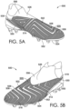
- first areas 508 and the second areas 506 may be arranged in an alternating pattern formed on concentric shapes on a medial side of the upper 502. Specifically, the first areas 508 and the second areas 506 may alternate to form a pattern of concentric triangular shapes in at least a medial midfoot section 514 as illustrated in FIG. 5B .
- the concentric triangles may have rounded corners or pointed corners.
- the concentric pattern within the medial midfoot area 514 may be nested within a zig-zag pattern formed on a remainder of the knitted component 530, such as in a forefoot area 516, a heel area 518, and a lateral midfoot area 512 (shown in FIG. 5A ).
- the method 600 includes knitting a knitted component with a first yarn integrally knit with a second yarn.
- the first yarn includes a first core yarn and a first coating comprising a polymeric composition comprising one or more thermoplastic elastomers at least partially surrounding the first core yarn.
- Knitting the knitted component at block 602 may include knitting the first yarn such that the first yarn forms first areas on a first surface of the knitted component and knitting the second yarn such that the second yarn forms second areas on the first surface of the knitted component.
- method 600 includes, at block 606, forming the knitted component into an upper.
- the knitted component may already be knit to the shape of an upper and may be formed into an upper by folding one or more portions and/or joining one or more edges to create a foot-receiving void.
- the knitted component may be a larger textile piece and cut to the shape of the upper or to the shape of a component of the upper, such as an outer sheath.
- block 606 includes securing the thermoformed knitted component to one or more textile components by stitches, bonding, or the like.
- the core yarn is polyethylene terephthalate having a tenacity of about 1 gram per denier to about 10 grams per denier, about 3 grams to about 10 grams per denier, about 5 grams to about 10 grams per denier, about 1 gram to about 7 grams per denier, or about 1 gram to about 5 grams per denier (corresponding to about 9 grams per Tex to about 90 grams per Tex, about 27 grams to about 90 grams per Tex, about 45 grams to about 90 grams per Tex, about 9 grams to about 63 grams per Tex, or about 9 grams to about 45 grams per Tex).
- the coated yarn may be produced by extruding the coating (i.e., the first polymeric composition) onto the core yarn through an annular die or orifice such that the coating layer is axially centered surrounding the core yarn.
- the thickness of the coating applied to the core yarn may vary depending upon the application of the yarn.
- the coated yarn is used to produce a knitted textile.
- the coated yarn has a nominal average outer diameter of up to 1.00 millimeter, or of up to about 0.75 millimeters, or of up to about 0.5 millimeters, or of up to about 0.25 millimeters, or of up to about 0.2 millimeters, or of up to about 0.1 millimeters.
- the coating has a nominal average outer diameter of about 0.1 millimeters to about 1.00 millimeter, or about 0.1 millimeters to about 0.80 millimeters, or about 0.1 millimeters to about 0.60 millimeters.
- the coating on the yarn has an average radial coating thickness of about 50 micrometers to about 200 micrometers, or about 50 micrometers to about 150 micrometers, or about 50 micrometers to about 125 micrometers.
- the core yarn has a thickness of about 100 denier to about 200 denier, about 125 denier to about 175 denier, or about 150 denier to 160 denier (about 11.11 Tex to about 22.22 Tex, about 13.88 Tex to about 19.44 Tex, 16.66 Tex to about 17.77 Tex), and the coating has a nominal average outer diameter of about 0.10 millimeters to about 0.50 millimeters, or of about 0.10 millimeters to about 0.25 millimeters, or of about 0.10 millimeters to about 0.20 millimeters.
- the core yarn is polyethylene terephthalate having a thickness of about 100 denier to about 200 denier, about 125 denier to about 175 denier, or about 150 denier to about 160 denier (about 11.11 Tex to about 22.22 Tex, about 13.88 Tex to about 19.44 Tex, 16.66 Tex to about 17.77 Tex), and the coating has a nominal average outer diameter of about 0.10 millimeters to about 0.50 millimeters, or of about 0.10 millimeters to about 0.25 millimeters, or of about 0.10 millimeters to about 0.20 millimeters.
- the coated yarn has a net total diameter of from about 0.2 to about 0.6 millimeters, or about 0.3 to about 0.5 millimeters, or about 0.4 to about 0.6 millimeters
- a lubricating oil including, but not limited to, mineral oil or silicone oil, is present on the yarn at from about 0.5 percent to about 2 percent by weight, or from about 0.5 percent to about 1.5 percent by weight, or from about 0.5 percent to about 1 percent by weight.
- lubricating compositions are applied to the surface of the coated yarn before or during the process of forming the textile.
- thermoplastic composition and the lubricating composition are miscible when the thermoplastic composition is reflowed and resolidified in the presence of the lubricating composition.
- the reflowed and solidified composition may comprise the lubricating composition.
- the core yarn has a percent elongation of about 8 percent to about 30 percent, about 10 percent to about 30 percent, about 15 percent to about 30 percent, about 20 percent to about 30 percent, about 10 percent to about 25 percent, or about 10 percent to about 20 percent.
- the core yarn has a tenacity of about 1 gram per denier to about 10 grams per denier, about 2 grams per denier to about 8 grams per denier, about 4 grams per denier to about 8 grams per denier, or about 2 grams per denier to about 6 grams per denier (corresponding to about 9 grams per Tex to about 90 grams per Tex, about 18 grams to about 81 grams per Tex, about 36 grams to about 81 grams per Tex, or about 18 grams to about 54 grams per Tex).
- the polymeric composition of the first coating when thermoformed, has a melting temperature from about 100 degrees Celsius to about 210 degrees Celsius, optionally from about 110 degrees Celsius to about 195 degrees Celsius, from about 120 degrees Celsius to about 180 degrees Celsius, or from about 120 degrees Celsius to about 170 degrees Celsius. In another aspect, the first polymeric composition has a melting temperature greater than about 120 degrees Celsius and less than about 170 degrees Celsius, and optionally greater than about 130 degrees Celsius, and less than about 160 degrees Celsius.
- the melting temperature when the melting temperature is greater than 100 degrees Celsius, the integrity of articles formed from or incorporating the first polymeric composition is preserved if the articles briefly encounter similar temperatures, for example, during shipping or storage.
- articles formed from or incorporating the first polymeric composition when the melting temperature is greater than 100 degrees Celsius, or greater than 120 degrees Celsius, articles formed from or incorporating the first polymeric composition may be steamed without melting or uncontrollably fusing any polyester components incorporated in the articles for purposes such as fill, zonal surface, or comfort features, as well as stretch yarn used for snugness and fit features.
- the melting temperature when the melting temperature is greater than 120 degrees Celsius, materials incorporating the first or second polymeric composition disclosed herein are unlikely to soften and/or become tacky during use on a hot paved surface, a court surface, an artificial or natural football pitch, or a similar playing surface, track, or field.
- the higher the melting temperature of the first or second polymeric composition and the greater its enthalpy of melting the greater the ability of an article of footwear or athletic equipment incorporating or constructed from the first or second polymeric composition to withstand contact heating excursions, frictional surface heating events, or environmental heating excursions.
- such heat excursions may arise when the articles contact hot ground, court, or turf surfaces, or from frictional heating that comes from rubbing or abrasion when the articles contact another surface such as the ground, another shoe, a ball, or the like.
- Durometer Hardness Test The hardness of a material can be determined for a sample according to the test method detailed in ASTM D-2240 Durometer Hardness, using a Shore A scale.
- the free-standing shrinkage of yarns can be determined by the following method.
- a yarn sample is prepared according to the Yarn Sampling Procedure described below, and is cut to a length of approximately 30 millimeters with minimal tension at approximately room temperature (e.g., 20 degrees Celsius).
- the cut sample is placed in a 50 degrees Celsius or 70 degrees Celsius oven for 90 seconds.
- the sample is removed from the oven and measured.
- the percentage of shrink is calculated using the pre- and post-oven measurements of the sample by dividing the post-oven measurement by the pre-oven measurement, and multiplying by 100.
- Abrasion resistance including abrasion resistance simulating footwear upper scuffing
- Stoll abrasion test can be measured using the Stoll abrasion test, using samples prepared according to the Component Sampling Procedure, the Plaque or Film Sampling Procedure, or the Textile Sampling Procedure described below.
- the minimum number of samples for Stoll abrasion testing is 3. Samples used herein were hand-cut or die-cut into circles having a 112-millimeter diameter.
- the Stoll abrasion test is described more fully in ASTM D3886 and can be performed on the Atlas Universal Wear Tester. In the Stoll abrasion test, an abrading medium is moved over the stationary, mounted test sample and the visual appearance of the sample is monitored.
- the Stoll abrasion test is performed under pressure to simulate wear under normal usage.
- Abrasion loss is tested on cylindrical samples with a diameter of 16 ⁇ 0.2 millimeters and a minimum thickness of 6 millimeters cut using an ASTM standard hole drill. The abrasion loss is measured using Method B of ASTM D 5963-97a on a Gotech GT-7012-D abrasion test machine. The tests are performed as 22 degrees Celsius with an abrasion path of 40 meters. The Standard Rubber #1 used in the tests has a density of 1.336 grams per cubic centimeter (g/cm 3 ). The smaller the abrasion loss volume, the better the abrasion resistance.
- Water penetration for a sample is determined as follows, using a sample prepared according to the Component Sampling Procedure, the Plaque or Film Sampling Procedure, or the Textile Sampling Procedure described below.
- the specimen to be tested is mounted on a support base with a surface at a 45 degree angle to the horizontal.
- the support base includes a 152 millimeter diameter specimen holder inner ring.
- a specimen is allowed to equilibrate in the laboratory environment for at least 2 hours prior to testing. Test specimens are cut into 220 millimeter diameter circles. Thicker or harder materials such as leather or stiff synthetic leather will have 3 notches cut into the outer edge of the sample. Specimens may be hand cut or die cut.
- Test specimens for softer materials are cut to the same size, with length direction marked on the test specimens.
- Backing paper is prepared from white or off-white paper towels, coffee filters, or similar thin, absorbent papers. Backing paper is also cut into 220 millimeter diameter circles.
- One backing paper is prepared per test specimen and backing paper is not reused.
- the backing paper and a specimen are placed in a sample fixture, which is in turn placed in a spray testing device.
- the sample length direction should be parallel with the water flow direction.
- a funnel is adjusted to a height of 6 inches (152.4 millimeters) between a spray nozzle and the test specimen. The spray nozzle must be over the center of the test specimen. 250 ⁇ 2 milliliters of distilled water are added to the funnel, which causes water to spray onto the test specimen.
- the top surface is evaluated for water repellency.
- the sample fixture is removed from the support base and the backing paper is evaluated to determine if water penetrated through the sample. Water penetration is reported after visual assessment and samples are rated as "pass" or "fail” according to the degree of wetting. If no sticking or wetting of the top surface is observed, if slight random sticking or wetting of the top surface is observed, or if wetting of the top surface is observed at spray points, the sample is considered to pass. Further wetting beyond the spray points and/or including the back surface indicates the sample has failed the water penetration test.
- Test samples of textiles are prepared according to the Component Sampling Procedure or the Textile Sampling Procedure described below.
- a 10 inch by 8 inch (254 mm by 203 mm) test sample of the textile is mounted on the outer surface on a metal cylinder having a 10 inch circumference.
- the test sample and cylinder are mounted on the swinging arm of a robot, where the swinging arm is swung at a rate of 50 miles per hour, and impacts the equator of a stationary ball.
- the ball used is a regulation size Nike "MERLIN" football inflated to 0.80 bar.
- a high speed video camera is used to record the ball position immediately following the impact. Using the position in space and rotation of the ball across multiple frames of the images recorded by the high-speed video camera, software is then used to calculate the velocity and spin rate of the ball immediately after impact. Each measurement is repeated at least 3 times, and the results of the runs are averaged.
- Material Sampling Procedure can be used to obtain a neat sample of a polymeric composition or of a polymer, or, in some instances, a sample of a material used to form a polymeric composition or a polymer.
- the material is provided in media form, such as flakes, granules, powders, pellets, and the like. If a source of the polymeric material or polymer is not available in a neat form, the sample can be cut from a component or element containing the polymeric material or polymer, such as a composite element or a sole structure, thereby isolating a sample of the material.
- Plaque or Film Sampling Procedure A sample of a polymeric composition or a polymer is prepared. A portion of the polymer or polymeric composition is then molded into a film or plaque sized to fit the testing apparatus. For example, when using a Ross flexing tester, the plaque or film sample is sized to fit inside the Ross flexing tester used, the sample having dimensions of about 15 centimeters (cm) by 2.5 centimeters (cm) and a thickness of about 1 millimeter (mm) to about 4 millimeters (mm) by thermoforming the polymeric composition or polymer in a mold.
- the sample can be prepared by melting the polymer, charging the molten polymer into a mold, resolidifying the polymer in the shape of the mold, and removing the solidified molded sample from the mold.
- the sample of the polymer can be melted and then extruded into a film which is cut to size.
- the sample can be prepared by blending together the ingredients of the polymeric composition, melting the thermoplastic ingredients of the polymeric composition, charging the molten polymeric composition into a mold, resolidifying the polymeric composition in the shape of the mold, and removing the solidified molded sample from the mold.
- the sample of the polymer material can be prepared by mixing and melting the ingredients of the polymeric composition, and then the molten polymeric composition can be extruded into a film which is cut to size.
- the film is extruded as a web or sheet having a substantially constant film thickness for the film (within ⁇ 10 percent of the average film thickness) and cooled to solidify the resulting web or sheet.
- a sample having a surface area of 4 square centimeters is then cut from the resulting web or sheet.
- the film can be cut from a substrate of a footwear component, or from a backing substrate of a co-extruded sheet or web, thereby isolating the film. In either case, a sample having a surface area of 4 square centimeters is then cut from the resulting isolated film.
- Component Sampling Procedure This procedure can be used to obtain a sample of a material from a component of an article of footwear, an article of footwear, a component of an article of apparel, an article of apparel, a component of an article of sporting equipment, or an article of sporting equipment, including a sample of a polymeric composition or of a textile, or a portion of a textile, such as a thermoformed network.
- a sample including the material in a non-wet state e.g., at 25 degrees Celsius and 20 percent relative humidity
- the procedure can include separating the additional materials from the material to be tested.
- the sample is taken at a location along the article or component that provides a substantially constant material thickness for the material as present on the article or component (within plus or minus 10 percent of the average material thickness), such as, for an article of footwear, in a forefoot region, midfoot region, or a heel region of a ground-facing surface.
- a sample having a surface area of 4 square centimeters (cm 2 ) is used.
- the sample is cut into a size and shape (e.g., a dogbone-shaped sample) to fit into the testing apparatus.
- sample sizes with smaller cross-sectional surface areas can be taken and the area-specific measurements are adjusted accordingly.
Landscapes
- Engineering & Computer Science (AREA)
- Textile Engineering (AREA)
- Chemical & Material Sciences (AREA)
- Materials Engineering (AREA)
- Knitting Of Fabric (AREA)
- Footwear And Its Accessory, Manufacturing Method And Apparatuses (AREA)
- Socks And Pantyhose (AREA)
Claims (15)
- Eine Gestrickkomponente (130) mit einer ersten Oberfläche (105) und einer gegenüberliegenden zweiten Oberfläche, wobei die erste Oberfläche (105) der Gestrickkomponente (130) Folgendes umfasst: erste Bereiche (108) mit einem ersten Reibungskoeffizienten, wobei die ersten Bereiche (108) ein erstes Garn (210) mit einem Kern und einer Beschichtung umfassen, wobei die Beschichtung den Kern zumindest teilweise umgibt; und zweite Bereiche (106) mit einem zweiten Reibungskoeffizienten, der sich vom ersten Reibungskoeffizienten unterscheidet, wobei die zweiten Bereiche (106) ein zweites Garn (208) umfassen, wobei das zweite Garn (208) sich vom ersten Garn (210) unterscheidet, wobei die ersten Bereiche (108) mit den zweiten Bereichen (106) ein abwechselndes Muster bilden, sodass die ersten Bereiche 40 % bis 80 % einer Gesamtfläche der ersten Oberfläche (105) ausmachen, dadurch gekennzeichnet, dass der erste Reibungskoeffizient größer ist als der zweite Reibungskoeffizient, wobei der zweite Reibungskoeffizient der zweiten Bereiche in einem Bereich liegt, der etwa 10 % bis etwa 75 % unter dem ersten Reibungskoeffizienten der ersten Bereiche liegt.
- Die Gestrickkomponente (130) nach Anspruch 1, wobei die Beschichtung ein thermoplastisches Elastomer umfasst.
- Die Gestrickkomponente (130) nach irgendeinem der Ansprüche von 1 bis 2, wobei ein erster Bereich der ersten Bereiche (108) ein thermogeformtes Netzwerk aus ineinander geschlungenen (interlooped) Garnen umfasst, die den Kern und die Beschichtung umfassen, wobei die Beschichtung das thermogeformte Netzwerk aus ineinander geschlungenen Garnen konsolidiert, indem sie mindestens einen Abschnitt des Kerns umgibt und zumindest einen Abschnitt der Zwischenräume zwischen den Garnen im thermogeformten Netzwerk aus ineinander geschlungenen Garnen ausfüllt.
- Die Gestrickkomponente (130) nach irgendeinem der Ansprüche von 1 bis 3, wobei der erste Reibungskoeffizient und der zweite Reibungskoeffizient dynamische Reibungskoeffizienten sind.
- Die Gestrickkomponente (130) nach irgendeinem der Ansprüche von 1 bis 4, wobei die Beschichtung des ersten Garns (210) eine thermoplastische Polymerzusammensetzung umfasst, wobei das zweite Garn (208) ein thermoplastisches Material umfasst, und wobei das zweite Garn (208) nicht die thermoplastische Polymerzusammensetzung beinhaltet, die die Beschichtung des ersten Garns (210) bildet.
- Die Gestrickkomponente (130) nach irgendeinem der Ansprüche von 1 bis 5, wobei das abwechselnde Muster ein konzentrisches Muster ist, sodass die ersten Bereiche und die zweiten Bereiche koaxial sind und einen gemeinsamen Mittelpunkt haben.
- Die Gestrickkomponente (130) nach irgendeinem der Ansprüche von 1 bis 6, wobei ein erster Bereich der ersten Bereiche (108) und ein zweiter Bereich der zweiten Bereiche (106) im abwechselnden Muster aufeinanderfolgen, wobei eine Grenze zwischen dem ersten Bereich (108) und dem zweiten Bereich (106) gekrümmt ist, oder wobei ein erster Bereich der ersten Bereiche (108) und ein zweiter Bereich der zweiten Bereiche (106) im alternierenden Muster aufeinanderfolgen, wobei eine Grenze zwischen dem ersten Bereich und dem zweiten Bereich linear ist.
- Die Gestrickkomponente (130) nach irgendeinem der Ansprüche von 1 bis 7, wobei ein erster Bereich der ersten Bereiche (108) und ein zweiter Bereich der zweiten Bereiche (106) im alternierenden Muster aufeinanderfolgen, wobei ein erster erhabener Abschnitt der ersten Oberfläche (105) sich kontinuierlich über den ersten Bereich und den zweiten Bereich erstreckt, insbesondere wobei die Beschichtung des ersten Garns thermogeformt ist, um ein thermogeformtes Netzwerk aus ineinander geschlungenen Garnen zu erzeugen, und wobei der erste erhabene Abschnitt der ersten Oberfläche (105) Teil des thermogeformten Netzwerks ist.
- Ein gestricktes Fußbekleidungsartikel-Oberteil (102), das aus der Gestrickkomponente (130) nach irgendeinem der Ansprüche von 1 bis 8 geformt ist, wobei die erste Oberfläche (105) der Gestrickkomponente ein nach außen gerichteter Oberflächenabschnitt (105) ist und die gegenüberliegende zweite Oberfläche ein gegenüberliegender nach innen gerichteter Oberflächenabschnitt ist, wobei die ersten Bereiche (108) ein erstes abwechselndes Muster mit den zweiten Bereichen (106) in einem ersten Bereich des nach außen gerichteten Oberflächenabschnitts (105) bilden, sodass die ersten Bereiche 40 % bis 80 % einer Gesamtfläche des nach außen gerichteten Oberflächenabschnitts (105) im ersten Bereich ausmachen.
- Das gestrickte Fußbekleidungsartikel-Oberteil (102) nach Anspruch 9, wobei die ersten Bereiche (108) und die zweiten Bereiche (106) ein zweites abwechselndes Muster in einem zweiten Bereich des nach außen gerichteten Oberflächenabschnitts (105) bilden, sodass die ersten Bereiche 40 % bis 80 % einer Gesamtfläche des nach außen gerichteten Oberflächenabschnitts (105) im zweiten Bereich ausmachen, insbesondere wobei der erste Bereich an einem medialen Abschnitt des gestrickten Fußbekleidungsartikel-Oberteils (102) liegt und der zweite Bereich an einem lateralen Abschnitt des gestrickten Fußbekleidungsartikel-Oberteils (102) liegt.
- Das gestrickte Fußbekleidungsartikel-Oberteil (102) nach irgendeinem der Ansprüche von 9 bis 10, wobei das erste abwechselnde Muster ein konzentrisches Muster ist, oder wobei das erste abwechselnde Muster mindestens eines von einer gekrümmten Grenze zwischen einem ersten Bereich der ersten Bereiche (108) und einem zweiten Bereich der zweiten Bereiche (106) oder einer linearen Grenze zwischen dem ersten Bereich der ersten Bereiche (108) und dem zweiten Bereich der zweiten Bereiche (106) umfasst.
- Das gestrickte Fußbekleidungsartikel-Oberteil (102) nach irgendeinem der Ansprüche von 9 bis 11, wobei ein erster Bereich der ersten Bereiche (108) ein thermogeformtes Netzwerk aus ineinander geschlungenen Garnen umfasst, die jeweils einen Kern aufweisen, sodass ein thermoplastisches Elastomer einer Beschichtung die ineinander geschlungenen Garne verfestigt, indem es mindestens einen Abschnitt des Kerns umgibt und zumindest einen Abschnitt der Zwischenräume zwischen den Garnen im thermogeformten Netzwerk aus ineinander geschlungenen Garnen ausfüllt.
- Das gestrickte Fußbekleidungsartikel-Oberteil nach irgendeinem der Ansprüche von 9 bis 12, wobei sich der erste Bereich über mindestens einen Abschnitt eines Zehenbereichs des gestrickten Fußbekleidungsartikel-Oberteils erstreckt, oder wobei sich der erste Bereich über mindestens einen Abschnitt eines Zehenbereichs des gestrickten Fußbekleidungsartikel-Oberteils und über mindestens eine von einer medialen Seite und einer lateralen Seite des gestrickten Fußbekleidungsartikel-Oberteils erstreckt.
- Ein Verfahren zur Herstellung einer Gestrickkomponente (130) mit einer ersten Oberfläche (105) und einer gegenüberliegenden zweiten Oberfläche, wobei das Verfahren Folgendes umfasst: Verstricken eines ersten Garns (210) und eines zweiten Garns (208) zur Gestrickkomponente (130), wobei das erste Garn (210) ein thermoplastisches Elastomer umfasst, wobei das zweite Garn (208) sich vom ersten Garn (210) unterscheidet; und Thermoformen der ersten Oberfläche (105) der Gestrickkomponente (130), wobei die erste Oberfläche (105) der Gestrickkomponente (130) Folgendes umfasst: erste Bereiche (108) mit einem ersten Reibungskoeffizienten, wobei die ersten Bereiche (108) ein thermogeformtes Netzwerk aus ineinander geschlungenen Garnen umfassen, die jeweils den Kern aufweisen, sodass ein thermoplastisches Elastomer der Beschichtung die ineinander geschlungenen Garne konsolidiert, indem es mindestens einen Abschnitt jedes Kerns umgibt und mindestens einen Abschnitt der Zwischenräume zwischen den Garnen (210) im thermogeformten Netzwerk aus ineinander geschlungenen Garnen ausfüllt, und zweite Bereiche (106) mit einem zweiten Reibungskoeffizienten, der sich vom ersten Reibungskoeffizienten unterscheidet, wobei die zweiten Bereiche (106) das zweite Garn (208) umfassen, wobei die ersten Bereiche (108) ein abwechselndes Muster mit den zweiten Bereichen (106) bilden, sodass die ersten Bereiche 40 % bis 80 % einer Gesamtfläche der ersten Oberfläche (105) ausmachen, dadurch gekennzeichnet, dass der erste Reibungskoeffizient größer ist als der zweite Reibungskoeffizient, und wobei der zweite Reibungskoeffizient der zweiten Bereiche in einem Bereich liegt, der etwa 10 % bis etwa 75 % unter dem ersten Reibungskoeffizienten der ersten Bereiche liegt.
- Das Verfahren nach Anspruch 14, wobei das Thermoformen der ersten Oberfläche ferner das Formen der ersten Oberfläche mit einem oder mehreren erhabenen Abschnitten der ersten Oberfläche umfasst, wobei sich der eine oder die mehreren erhabenen Abschnitte über eine Vielzahl der ersten Bereiche und eine Vielzahl der zweiten Bereiche erstrecken, wobei der eine oder die mehreren erhabenen Abschnitte Teil des thermogeformten Netzwerks aus ineinander geschlungenen Garnen sind.
Priority Applications (1)
| Application Number | Priority Date | Filing Date | Title |
|---|---|---|---|
| EP25186164.7A EP4617415A3 (de) | 2021-09-14 | 2021-09-15 | Gestrickte komponenten und artikel für verbesserte ballkontrolle und haltbarkeit |
Applications Claiming Priority (2)
| Application Number | Priority Date | Filing Date | Title |
|---|---|---|---|
| US202163244121P | 2021-09-14 | 2021-09-14 | |
| PCT/US2021/050495 WO2023043438A1 (en) | 2021-09-14 | 2021-09-15 | Knitted components and articles for improved ball control and durability |
Related Child Applications (1)
| Application Number | Title | Priority Date | Filing Date |
|---|---|---|---|
| EP25186164.7A Division EP4617415A3 (de) | 2021-09-14 | 2021-09-15 | Gestrickte komponenten und artikel für verbesserte ballkontrolle und haltbarkeit |
Publications (2)
| Publication Number | Publication Date |
|---|---|
| EP4402311A1 EP4402311A1 (de) | 2024-07-24 |
| EP4402311B1 true EP4402311B1 (de) | 2025-07-02 |
Family
ID=78080584
Family Applications (2)
| Application Number | Title | Priority Date | Filing Date |
|---|---|---|---|
| EP21787253.0A Active EP4402311B1 (de) | 2021-09-14 | 2021-09-15 | Gestrickte komponenten und artikel für verbesserte ballkontrolle und haltbarkeit |
| EP25186164.7A Pending EP4617415A3 (de) | 2021-09-14 | 2021-09-15 | Gestrickte komponenten und artikel für verbesserte ballkontrolle und haltbarkeit |
Family Applications After (1)
| Application Number | Title | Priority Date | Filing Date |
|---|---|---|---|
| EP25186164.7A Pending EP4617415A3 (de) | 2021-09-14 | 2021-09-15 | Gestrickte komponenten und artikel für verbesserte ballkontrolle und haltbarkeit |
Country Status (7)
| Country | Link |
|---|---|
| US (2) | US20240277103A1 (de) |
| EP (2) | EP4402311B1 (de) |
| JP (2) | JP7574503B2 (de) |
| KR (1) | KR102788149B1 (de) |
| CN (4) | CN119491317A (de) |
| TW (2) | TWI838655B (de) |
| WO (1) | WO2023043438A1 (de) |
Families Citing this family (7)
| Publication number | Priority date | Publication date | Assignee | Title |
|---|---|---|---|---|
| USD1010986S1 (en) * | 2020-03-31 | 2024-01-16 | Nike, Inc. | Shoe |
| EP4402311B1 (de) * | 2021-09-14 | 2025-07-02 | NIKE Innovate C.V. | Gestrickte komponenten und artikel für verbesserte ballkontrolle und haltbarkeit |
| USD1032180S1 (en) * | 2022-07-06 | 2024-06-25 | Nike, Inc. | Shoe |
| USD1032179S1 (en) * | 2022-07-06 | 2024-06-25 | Nike, Inc. | Shoe |
| IT202300012498A1 (it) * | 2023-06-16 | 2024-12-16 | Tex Tech S R L | Tessuto 3d fonoassorbente/fonocorrettore |
| WO2025038529A1 (en) * | 2023-08-11 | 2025-02-20 | Nike Innovate C.V. | Article of footwear with enhanced durability features |
| DE102024124309A1 (de) | 2024-08-26 | 2026-02-26 | Adidas Ag | Oberteil für einen Schuh mit einer Mikrostrukturoberfläche |
Citations (1)
| Publication number | Priority date | Publication date | Assignee | Title |
|---|---|---|---|---|
| US11001947B2 (en) * | 2016-11-08 | 2021-05-11 | Nike, Inc. | Articles with integrally knit heat-treatable yarn |
Family Cites Families (23)
| Publication number | Priority date | Publication date | Assignee | Title |
|---|---|---|---|---|
| US20130255103A1 (en) * | 2012-04-03 | 2013-10-03 | Nike, Inc. | Apparel And Other Products Incorporating A Thermoplastic Polymer Material |
| CN104781165B (zh) * | 2012-09-28 | 2016-10-19 | 三和技术株式会社 | 由织带构成的输送带和传动带及使用该输送带的输送装置 |
| DE102013207155B4 (de) * | 2013-04-19 | 2020-04-23 | Adidas Ag | Schuhoberteil |
| WO2015101631A1 (en) * | 2013-12-31 | 2015-07-09 | Sense Textile B.V. | Stretchable textile stay and transfer sheet |
| CN103989291A (zh) * | 2014-05-22 | 2014-08-20 | 东莞市杰乐盛世运动用品有限公司 | 鞋面及其制作方法 |
| DE102014220087B4 (de) * | 2014-10-02 | 2016-05-12 | Adidas Ag | Flachgestricktes Schuhoberteil für Sportschuhe |
| CN204292338U (zh) * | 2014-12-15 | 2015-04-29 | 丁守企业股份有限公司 | 凹凸鞋面结构 |
| US9888742B2 (en) * | 2015-09-11 | 2018-02-13 | Nike, Inc. | Article of footwear with knitted component having plurality of graduated projections |
| US10524530B2 (en) * | 2016-02-16 | 2020-01-07 | Nike, Inc. | Upper for an article of footwear with at least one molded thermoplastic polymer element |
| CN109714998B (zh) * | 2016-08-12 | 2021-11-02 | 耐克创新有限合伙公司 | 具有带有第一纱和第二纱的第一区段的物品 |
| WO2018089686A1 (en) * | 2016-11-09 | 2018-05-17 | Nike Innovate C.V. | Textiles and articles, and processes for making the same |
| EP3715117B1 (de) * | 2017-09-29 | 2024-03-06 | NIKE Innovate C.V. | Strukturell gefärbte textilartikel und verfahren zur herstellung strukturell gefärbter textilartikel |
| DE102017223737B4 (de) * | 2017-12-22 | 2025-08-28 | Adidas Ag | Verfahren zur Herstellung eines Schuhoberteils |
| DE102017223746B4 (de) * | 2017-12-22 | 2024-03-14 | Adidas Ag | Rundstrick-Schuhoberteil |
| US11375774B2 (en) * | 2018-08-09 | 2022-07-05 | Nike, Inc. | Knitted component having a knitted anchor portion |
| JP7349122B2 (ja) * | 2019-03-13 | 2023-09-22 | 三陽メリヤス株式会社 | 筒状編地の製造方法 |
| WO2020214450A1 (en) * | 2019-04-17 | 2020-10-22 | Nike Innovate C.V. | Lightweight knitted upper, an article of footwear and a method of manufacture |
| WO2020243444A2 (en) * | 2019-05-31 | 2020-12-03 | Nike Innovate C.V. | Knitted component with an inner layer having a thermoplastic material and related method |
| US11678721B2 (en) * | 2019-07-24 | 2023-06-20 | Nike, Inc. | Polyolefin-based synthetic leather and articles formed therefrom |
| CN114468459B (zh) * | 2019-08-02 | 2024-09-10 | 耐克创新有限合伙公司 | 用于鞋类物品的鞋外底 |
| CN114929054B (zh) * | 2020-01-08 | 2024-08-06 | 耐克创新有限合伙公司 | 具有两种纱线类型的用于鞋类制品的鞋面 |
| CN111455536B (zh) * | 2020-05-13 | 2024-08-09 | 信泰(福建)科技有限公司 | 轻质超强物性通透面料、鞋面以及面料的制作方法 |
| EP4402311B1 (de) * | 2021-09-14 | 2025-07-02 | NIKE Innovate C.V. | Gestrickte komponenten und artikel für verbesserte ballkontrolle und haltbarkeit |
-
2021
- 2021-09-15 EP EP21787253.0A patent/EP4402311B1/de active Active
- 2021-09-15 WO PCT/US2021/050495 patent/WO2023043438A1/en not_active Ceased
- 2021-09-15 US US18/691,663 patent/US20240277103A1/en active Pending
- 2021-09-15 EP EP25186164.7A patent/EP4617415A3/de active Pending
- 2021-09-15 CN CN202411905409.8A patent/CN119491317A/zh active Pending
- 2021-09-15 KR KR1020247012249A patent/KR102788149B1/ko active Active
- 2021-09-15 CN CN202180102393.5A patent/CN117957344B/zh active Active
- 2021-09-15 JP JP2024516492A patent/JP7574503B2/ja active Active
- 2021-10-19 TW TW110138761A patent/TWI838655B/zh active
- 2021-10-19 TW TW113108951A patent/TWI853782B/zh active
- 2021-12-14 CN CN202111527318.1A patent/CN115804490B/zh active Active
- 2021-12-14 CN CN202123136486.6U patent/CN217510002U/zh active Active
-
2022
- 2022-09-14 US US17/944,803 patent/US20230087149A1/en active Pending
-
2024
- 2024-10-16 JP JP2024180774A patent/JP2025026836A/ja active Pending
Patent Citations (1)
| Publication number | Priority date | Publication date | Assignee | Title |
|---|---|---|---|---|
| US11001947B2 (en) * | 2016-11-08 | 2021-05-11 | Nike, Inc. | Articles with integrally knit heat-treatable yarn |
Also Published As
| Publication number | Publication date |
|---|---|
| WO2023043438A1 (en) | 2023-03-23 |
| CN115804490A (zh) | 2023-03-17 |
| CN117957344A (zh) | 2024-04-30 |
| TW202311588A (zh) | 2023-03-16 |
| JP2024535238A (ja) | 2024-09-30 |
| US20240277103A1 (en) | 2024-08-22 |
| EP4617415A3 (de) | 2025-10-29 |
| JP2025026836A (ja) | 2025-02-26 |
| EP4617415A2 (de) | 2025-09-17 |
| TWI838655B (zh) | 2024-04-11 |
| CN217510002U (zh) | 2022-09-30 |
| EP4402311A1 (de) | 2024-07-24 |
| CN119491317A (zh) | 2025-02-21 |
| KR20240054398A (ko) | 2024-04-25 |
| JP7574503B2 (ja) | 2024-10-28 |
| CN117957344B (zh) | 2025-01-03 |
| TW202426723A (zh) | 2024-07-01 |
| KR102788149B1 (ko) | 2025-03-28 |
| CN115804490B (zh) | 2026-01-09 |
| TWI853782B (zh) | 2024-08-21 |
| US20230087149A1 (en) | 2023-03-23 |
Similar Documents
| Publication | Publication Date | Title |
|---|---|---|
| US20240298743A1 (en) | Textiles and articles and processes for making the same | |
| EP4402311B1 (de) | Gestrickte komponenten und artikel für verbesserte ballkontrolle und haltbarkeit | |
| US20250351916A1 (en) | Articles of footwear with knitted components and methods of manufacturing the same | |
| EP4428280A1 (de) | Schuhartikel mit gestrickten komponenten und verfahren zur herstellung davon | |
| US20240260717A1 (en) | Article of footwear for improved ball control |
Legal Events
| Date | Code | Title | Description |
|---|---|---|---|
| STAA | Information on the status of an ep patent application or granted ep patent |
Free format text: STATUS: UNKNOWN |
|
| STAA | Information on the status of an ep patent application or granted ep patent |
Free format text: STATUS: THE INTERNATIONAL PUBLICATION HAS BEEN MADE |
|
| PUAI | Public reference made under article 153(3) epc to a published international application that has entered the european phase |
Free format text: ORIGINAL CODE: 0009012 |
|
| STAA | Information on the status of an ep patent application or granted ep patent |
Free format text: STATUS: REQUEST FOR EXAMINATION WAS MADE |
|
| 17P | Request for examination filed |
Effective date: 20240412 |
|
| AK | Designated contracting states |
Kind code of ref document: A1 Designated state(s): AL AT BE BG CH CY CZ DE DK EE ES FI FR GB GR HR HU IE IS IT LI LT LU LV MC MK MT NL NO PL PT RO RS SE SI SK SM TR |
|
| GRAP | Despatch of communication of intention to grant a patent |
Free format text: ORIGINAL CODE: EPIDOSNIGR1 |
|
| STAA | Information on the status of an ep patent application or granted ep patent |
Free format text: STATUS: GRANT OF PATENT IS INTENDED |
|
| DAV | Request for validation of the european patent (deleted) | ||
| DAX | Request for extension of the european patent (deleted) | ||
| INTG | Intention to grant announced |
Effective date: 20240903 |
|
| GRAJ | Information related to disapproval of communication of intention to grant by the applicant or resumption of examination proceedings by the epo deleted |
Free format text: ORIGINAL CODE: EPIDOSDIGR1 |
|
| STAA | Information on the status of an ep patent application or granted ep patent |
Free format text: STATUS: REQUEST FOR EXAMINATION WAS MADE |
|
| GRAP | Despatch of communication of intention to grant a patent |
Free format text: ORIGINAL CODE: EPIDOSNIGR1 |
|
| STAA | Information on the status of an ep patent application or granted ep patent |
Free format text: STATUS: GRANT OF PATENT IS INTENDED |
|
| INTC | Intention to grant announced (deleted) | ||
| INTG | Intention to grant announced |
Effective date: 20250128 |
|
| GRAS | Grant fee paid |
Free format text: ORIGINAL CODE: EPIDOSNIGR3 |
|
| GRAA | (expected) grant |
Free format text: ORIGINAL CODE: 0009210 |
|
| STAA | Information on the status of an ep patent application or granted ep patent |
Free format text: STATUS: THE PATENT HAS BEEN GRANTED |
|
| AK | Designated contracting states |
Kind code of ref document: B1 Designated state(s): AL AT BE BG CH CY CZ DE DK EE ES FI FR GB GR HR HU IE IS IT LI LT LU LV MC MK MT NL NO PL PT RO RS SE SI SK SM TR |
|
| P01 | Opt-out of the competence of the unified patent court (upc) registered |
Free format text: CASE NUMBER: APP_24993/2025 Effective date: 20250526 |
|
| REG | Reference to a national code |
Ref country code: GB Ref legal event code: FG4D |
|
| REG | Reference to a national code |
Ref country code: CH Ref legal event code: EP |
|
| REG | Reference to a national code |
Ref country code: DE Ref legal event code: R096 Ref document number: 602021033453 Country of ref document: DE |
|
| REG | Reference to a national code |
Ref country code: IE Ref legal event code: FG4D |
|
| PGFP | Annual fee paid to national office [announced via postgrant information from national office to epo] |
Ref country code: DE Payment date: 20250722 Year of fee payment: 5 |
|
| PGFP | Annual fee paid to national office [announced via postgrant information from national office to epo] |
Ref country code: GB Payment date: 20250724 Year of fee payment: 5 |
|
| PGFP | Annual fee paid to national office [announced via postgrant information from national office to epo] |
Ref country code: AT Payment date: 20251020 Year of fee payment: 5 Ref country code: FR Payment date: 20250708 Year of fee payment: 5 |
|
| REG | Reference to a national code |
Ref country code: NL Ref legal event code: MP Effective date: 20250702 |
|
| PG25 | Lapsed in a contracting state [announced via postgrant information from national office to epo] |
Ref country code: PT Free format text: LAPSE BECAUSE OF FAILURE TO SUBMIT A TRANSLATION OF THE DESCRIPTION OR TO PAY THE FEE WITHIN THE PRESCRIBED TIME-LIMIT Effective date: 20251103 |
|
| PG25 | Lapsed in a contracting state [announced via postgrant information from national office to epo] |
Ref country code: NL Free format text: LAPSE BECAUSE OF FAILURE TO SUBMIT A TRANSLATION OF THE DESCRIPTION OR TO PAY THE FEE WITHIN THE PRESCRIBED TIME-LIMIT Effective date: 20250702 |
|
| REG | Reference to a national code |
Ref country code: AT Ref legal event code: MK05 Ref document number: 1809350 Country of ref document: AT Kind code of ref document: T Effective date: 20250702 |
|
| PG25 | Lapsed in a contracting state [announced via postgrant information from national office to epo] |
Ref country code: IS Free format text: LAPSE BECAUSE OF FAILURE TO SUBMIT A TRANSLATION OF THE DESCRIPTION OR TO PAY THE FEE WITHIN THE PRESCRIBED TIME-LIMIT Effective date: 20251102 |
|
| PG25 | Lapsed in a contracting state [announced via postgrant information from national office to epo] |
Ref country code: NO Free format text: LAPSE BECAUSE OF FAILURE TO SUBMIT A TRANSLATION OF THE DESCRIPTION OR TO PAY THE FEE WITHIN THE PRESCRIBED TIME-LIMIT Effective date: 20251002 |
|
| REG | Reference to a national code |
Ref country code: LT Ref legal event code: MG9D |
|
| PG25 | Lapsed in a contracting state [announced via postgrant information from national office to epo] |
Ref country code: AT Free format text: LAPSE BECAUSE OF FAILURE TO SUBMIT A TRANSLATION OF THE DESCRIPTION OR TO PAY THE FEE WITHIN THE PRESCRIBED TIME-LIMIT Effective date: 20250702 |
|
| PG25 | Lapsed in a contracting state [announced via postgrant information from national office to epo] |
Ref country code: FI Free format text: LAPSE BECAUSE OF FAILURE TO SUBMIT A TRANSLATION OF THE DESCRIPTION OR TO PAY THE FEE WITHIN THE PRESCRIBED TIME-LIMIT Effective date: 20250702 |
|
| PG25 | Lapsed in a contracting state [announced via postgrant information from national office to epo] |
Ref country code: HR Free format text: LAPSE BECAUSE OF FAILURE TO SUBMIT A TRANSLATION OF THE DESCRIPTION OR TO PAY THE FEE WITHIN THE PRESCRIBED TIME-LIMIT Effective date: 20250702 |
|
| PG25 | Lapsed in a contracting state [announced via postgrant information from national office to epo] |
Ref country code: GR Free format text: LAPSE BECAUSE OF FAILURE TO SUBMIT A TRANSLATION OF THE DESCRIPTION OR TO PAY THE FEE WITHIN THE PRESCRIBED TIME-LIMIT Effective date: 20251003 |
|
| PG25 | Lapsed in a contracting state [announced via postgrant information from national office to epo] |
Ref country code: CZ Free format text: LAPSE BECAUSE OF FAILURE TO SUBMIT A TRANSLATION OF THE DESCRIPTION OR TO PAY THE FEE WITHIN THE PRESCRIBED TIME-LIMIT Effective date: 20250702 Ref country code: SE Free format text: LAPSE BECAUSE OF FAILURE TO SUBMIT A TRANSLATION OF THE DESCRIPTION OR TO PAY THE FEE WITHIN THE PRESCRIBED TIME-LIMIT Effective date: 20250702 |
|
| PG25 | Lapsed in a contracting state [announced via postgrant information from national office to epo] |
Ref country code: LV Free format text: LAPSE BECAUSE OF FAILURE TO SUBMIT A TRANSLATION OF THE DESCRIPTION OR TO PAY THE FEE WITHIN THE PRESCRIBED TIME-LIMIT Effective date: 20250702 |
|
| PG25 | Lapsed in a contracting state [announced via postgrant information from national office to epo] |
Ref country code: PL Free format text: LAPSE BECAUSE OF FAILURE TO SUBMIT A TRANSLATION OF THE DESCRIPTION OR TO PAY THE FEE WITHIN THE PRESCRIBED TIME-LIMIT Effective date: 20250702 Ref country code: BG Free format text: LAPSE BECAUSE OF FAILURE TO SUBMIT A TRANSLATION OF THE DESCRIPTION OR TO PAY THE FEE WITHIN THE PRESCRIBED TIME-LIMIT Effective date: 20250702 |
|
| PG25 | Lapsed in a contracting state [announced via postgrant information from national office to epo] |
Ref country code: RS Free format text: LAPSE BECAUSE OF FAILURE TO SUBMIT A TRANSLATION OF THE DESCRIPTION OR TO PAY THE FEE WITHIN THE PRESCRIBED TIME-LIMIT Effective date: 20251002 |
|
| PG25 | Lapsed in a contracting state [announced via postgrant information from national office to epo] |
Ref country code: ES Free format text: LAPSE BECAUSE OF FAILURE TO SUBMIT A TRANSLATION OF THE DESCRIPTION OR TO PAY THE FEE WITHIN THE PRESCRIBED TIME-LIMIT Effective date: 20250702 |
|
| PG25 | Lapsed in a contracting state [announced via postgrant information from national office to epo] |
Ref country code: RO Free format text: LAPSE BECAUSE OF FAILURE TO SUBMIT A TRANSLATION OF THE DESCRIPTION OR TO PAY THE FEE WITHIN THE PRESCRIBED TIME-LIMIT Effective date: 20250702 |