EP4401397B1 - Halbtonrasterung von nebeneinanderliegenden gruppierten verteilten punkten - Google Patents
Halbtonrasterung von nebeneinanderliegenden gruppierten verteilten punkten Download PDFInfo
- Publication number
- EP4401397B1 EP4401397B1 EP24020006.3A EP24020006A EP4401397B1 EP 4401397 B1 EP4401397 B1 EP 4401397B1 EP 24020006 A EP24020006 A EP 24020006A EP 4401397 B1 EP4401397 B1 EP 4401397B1
- Authority
- EP
- European Patent Office
- Prior art keywords
- juxtaposed
- ink
- dispersed
- fluorescent
- clusters
- Prior art date
- Legal status (The legal status is an assumption and is not a legal conclusion. Google has not performed a legal analysis and makes no representation as to the accuracy of the status listed.)
- Active
Links
Images


Classifications
-
- H—ELECTRICITY
- H04—ELECTRIC COMMUNICATION TECHNIQUE
- H04N—PICTORIAL COMMUNICATION, e.g. TELEVISION
- H04N1/00—Scanning, transmission or reproduction of documents or the like, e.g. facsimile transmission; Details thereof
- H04N1/46—Colour picture communication systems
- H04N1/54—Conversion of colour picture signals to a plurality of signals some of which represent particular mixed colours, e.g. for textile printing
-
- H—ELECTRICITY
- H04—ELECTRIC COMMUNICATION TECHNIQUE
- H04N—PICTORIAL COMMUNICATION, e.g. TELEVISION
- H04N1/00—Scanning, transmission or reproduction of documents or the like, e.g. facsimile transmission; Details thereof
- H04N1/40—Picture signal circuits
- H04N1/405—Halftoning, i.e. converting the picture signal of a continuous-tone original into a corresponding signal showing only two levels
- H04N1/4055—Halftoning, i.e. converting the picture signal of a continuous-tone original into a corresponding signal showing only two levels producing a clustered dots or a size modulated halftone pattern
-
- H—ELECTRICITY
- H04—ELECTRIC COMMUNICATION TECHNIQUE
- H04N—PICTORIAL COMMUNICATION, e.g. TELEVISION
- H04N1/00—Scanning, transmission or reproduction of documents or the like, e.g. facsimile transmission; Details thereof
- H04N1/23—Reproducing arrangements
- H04N1/2307—Circuits or arrangements for the control thereof, e.g. using a programmed control device, according to a measured quantity
- H04N1/2346—Circuits or arrangements for the control thereof, e.g. using a programmed control device, according to a measured quantity according to a detected condition or state of the reproducing device, e.g. temperature or ink quantity
-
- H—ELECTRICITY
- H04—ELECTRIC COMMUNICATION TECHNIQUE
- H04N—PICTORIAL COMMUNICATION, e.g. TELEVISION
- H04N1/00—Scanning, transmission or reproduction of documents or the like, e.g. facsimile transmission; Details thereof
- H04N1/46—Colour picture communication systems
- H04N1/52—Circuits or arrangements for halftone screening
-
- H—ELECTRICITY
- H04—ELECTRIC COMMUNICATION TECHNIQUE
- H04N—PICTORIAL COMMUNICATION, e.g. TELEVISION
- H04N1/00—Scanning, transmission or reproduction of documents or the like, e.g. facsimile transmission; Details thereof
- H04N1/46—Colour picture communication systems
- H04N1/56—Processing of colour picture signals
- H04N1/60—Colour correction or control
- H04N1/6083—Colour correction or control controlled by factors external to the apparatus
- H04N1/6086—Colour correction or control controlled by factors external to the apparatus by scene illuminant, i.e. conditions at the time of picture capture, e.g. flash, optical filter used, evening, cloud, daylight, artificial lighting, white point measurement, colour temperature
Definitions
- the present invention relates to the field of special halftoning techniques for printing security documents. It also relates to methods and devices for authenticating documents and valuable products by full color fluorescent images that are invisible under day light and visible under ultraviolet (UV) light.
- UV ultraviolet
- the present invention provides enabling technologies for rotogravure printing, pad printing, offset printing, ink-jet printing, electrophotography and flexography, with the purpose of counterfeit protection of banknotes, fiscal stamps, checks, credit cards, passports, identity cards, travel documents, legal documents, valuable business documents, event tickets, transportation tickets, as well as packages of goods such as medical drugs, watches, software, skincare devices, and alcoholic beverages.
- the present invention also applies to domains where protective and decorative features can be combined, for example branded articles, packages and labels for luxury goods (watches, jewelry, perfumes, body care liquids, alcoholic drinks) and clothes (e.g. dresses, skirts, blouses, jackets and pants).
- the present invention also enables creating digital fluorescent color images for commercial art, decoration, publicity displays, fashion articles, and night life, where fluorescent images viewed under UV illumination in the dark have a strongly appealing effect.
- This prior art reproduction framework is adequate for creating fluorescent images printed on an offset printer.
- the screen dot imaged on an offset plate can have any desirable size, from a very small size to the full coverage of the screen dot.
- other printing technologies such as gravure must, when creating the gravure cylinder, keep some walls between adjacent screen cells. Therefore, there is a need to expand the prior art juxtaposed clustered dot halftoning method developed mainly for offset, electrophotography and ink-jet, in order to account for the constraints imposed by gravure, rotogravure, pad printing, and flexography.
- the new disclosed juxtaposed dispersed dot halftoning method also improves the quality of offset and ink-jet printing with fluorescent inks and of electrophotography with fluorescent solid or liquid toners.
- a new juxtaposed dispersed-dot halftoning method that can be embodied by a computer program running on a computing system for creating color images, among them also color images that are visible only under UV light.
- This improved method is applicable to printing systems whose ink is deposited into cavities (rotogravure printing, gravure printing, pad printing), deposited on top of raised elements (flexography), deposited onto ink accepting locations of an offset plate, directly printed on a substrate (by inkjet) or transferred from the photoconductor drum of an electrophotography printer to paper.
- the cavities or the raised elements need to be surrounded by boundaries.
- the present invention combines the advantages of juxtaposed halftoning where different colorants do not overlap with dispersed dot halftoning, which ensures that small pixel wide halftone structures (active pixel segments) are to a large extent surrounded by border structures (non-active pixels).
- the disclosed juxtaposed dispersed dot halftoning method combines juxtaposed clustered dot halftoning and dispersed dot halftoning to create clusters of juxtaposed dispersed colorant dots laid out side by side and that are each one surrounded by unprinted space. Thanks to the unprinted space surrounding the clusters of dispersed halftoned dots, small misregistrations of the ink halftone separations do not lead to undesired ink overlaps of neighboring clusters of dispersed dots. In addition, thanks to the use of random threshold error-diffusion to generate the dispersed dot halftones embodied by clusters of pixel segments. Small misregistrations do not modify the overall colorant color.
- the ink level reduction factor used for dispersed dot halftoning it is possible to control the size of the horizontal, vertical and possibly diagonal pixel segments that form the clusters of dispersed halftone dots.
- these pixel segments define the areas that are engraved on the rotogravure cylinder. According to the size of these areas, more or less ink is stored in these engravings at rotogravure printing time. The quantity of stored ink that is transferred onto the print substrate (e.g. paper) determines the printed ink density.
- the thin pixel segment structures that constitute the juxtaposed clusters of dispersed ink dots specify the locations and areas to be engraved onto the cylinder.
- the fact that within the clusters of dispersed dots these segment structures have sizes that do not vary strongly enables creating a very stable rotogravure, offset, inkjet or electrophotography multi-ink colorant halftoning framework relying on clusters of densely spaced pixel segments.
- Such a framework enables high-quality color reproduction.
- juxtaposed dispersed dot halftoning is mainly used for printing color images visible under UV light with fluorescent inks, it can be also used in other applications, for example when printing color images viewable under daylight illumination with opaque custom inks.
- the method proposed for creating juxtaposed dispersed dot halftones involves in a first step the creation of juxtaposed clustered dots.
- Juxtaposed dispersed dots are generated by applying to the juxtaposed clustered dots a dispersed dot halftoning procedure.
- the juxtaposed clustered dots are surrounded by unprinted non-active space.
- the area of these clustered dots is a function of the surface coverages of its corresponding colorants that need to be printed.
- the juxtaposed dispersed dot halftone resulting from dispersed dot halftoning is formed by clusters of densely spaced pixel segments. These pixel segments are partly or fully surrounded by non-active pixels.
- These clusters of pixel segments cover the same area as the corresponding juxtaposed clustered dots. They are also surrounded by the same unprinted non-active space as the juxtaposed clustered dots. These pixel segments specify the locations and areas that have to be engraved in order to produce a rotogravure cylinder for rotogravure printing or a gravure plate for pad printing. Non-active pixels and non-active space specify locations without engravings.
- these pixel segments define the ink attracting locations and areas on the offset plate.
- electrophotography they define the positions and areas where toner particles are attracted by the photoconductor.
- inkjet printing they define the locations and areas of the inks on the substrate (paper). The halftones made of juxtaposed clusters of dispersed dots are printed by transferring them onto a color printer.
- the dispersed dot halftoning procedure can be tuned to create either longer pixel segments with less unprinted non-active space and more connections between neighboring segments or shorter pixel segments with more unprinted non-active space surrounding them and fewer connections between them.
- the ink level reduction factors associated to the fluorescent inks can be optimized to obtain fluorescent achromatic gray and white emission colors.
- the creation of juxtaposed clustered dots comprises the steps of (a) defining the number of colorants that can be placed within one screen element, (b) selecting among the available colorants the ones to be placed within the screen element, (c) creating the layout of the screen element, (d) calculating the ratio of surface coverages of the selected colorants, (e) according to that ratio, dimensioning the colorant cells associated to these colorants; and (f) scaling said colorant cells by a horizontal and vertical reduction factor corresponding to the square root of the sum of the colorant surface coverages.
- the juxtaposed dispersed dot halftoning procedure is preferably an error-diffusion procedure whose thresholds are randomly distributed, thereby ensuring that even for similar ink surface coverages each instance of the produced dispersed dot halftone has a completely different layout. Therefore, their embodiments, i.e. the instances of the produced juxtaposed clusters of densely spaced pixel segments have each time a different layout. Different layouts enable creating new colorants by overlays of several ink-specific juxtaposed clusters of densely spaced pixel segments without creating undesired moiré effects. Different layouts also tolerate small registration inaccuracies between the ink halftone layers without creating noticeable deviations in the reproduced color.
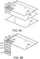
- the error diffusion procedure is applied several times on juxtaposed clustered dot halftones in order to create the corresponding juxtaposed dispersed dot halftones embodied by clusters of densely spaced pixel segments, one for each ink layer. These ink-specific clusters of pixel segments are preferably packed onto a multibit dispersed dot screen element ( FIG. 9B ) that is then stored in the screen element library.
- the created juxtaposed dispersed dot halftones can be part of a fluorescent color reproduction workflow for creating, within an output halftone space, fluorescent ink halftone separations for rotogravure printing, for offset printing, for inkjet or for electrophotography.
- a workflow comprises the steps of (a) selecting an input color image to be rendered as fluorescent color image visible only under UV light, (b) scanning the target output halftone space pixel by pixel and scanline by scanline, (c) determining the corresponding location within the selected input image, (d) obtaining the image color at that location, (e) accessing a previously established table that maps input image colors to surface coverages of the fluorescent colorants, (f) obtaining from said table the set of contributing colorants as well as their surface coverages, (g) obtaining according to said colorant surface coverages by accessing a screen element library a juxtaposed dispersed dot halftone, reading from the juxtaposed dispersed dot halftone the ink identifiers contributing to the current output pixel and copying them within
- an ink halftone separation contains the pixel segments that specify the locations and areas of the corresponding rotogravure cylinder to be engraved.
- the pixel segments specify the locations and areas of the raised elements, for offset printing, they specify the locations and areas of the ink attracting areas on the offset plate and for electrophotography, they specify the locations and areas of the photoconductor where toner will be attracted.
- the screen element library is a library of juxtaposed clustered or dispersed dot halftones.
- dispersed dot halftoning is applied to them in order to obtain the juxtaposed dispersed dot halftones, preferably embodied by ink-specific clusters of densely spaced pixel segments.
- fluorescent color reproduction is carried out in order to synthesize colorful images visible only under UV light. These colorful images which are invisible under daylight are difficult to counterfeit without the software operable for performing the steps necessary to synthesize fluorescent juxtaposed dispersed dot halftones.
- a rotogravure cylinder engraved according to the present invention incorporates densely spaced horizontal, vertical and possibly diagonal segments forming clusters which are surrounded by areas without segments. These sets of densely spaced clustered segments are laid out along diagonals having all the same orientation. In a smooth area of an image, successions of densely spaced clustered segments located along a section of a same diagonal have similarly sized areas. Clusters of pixel segments located on neighboring diagonals often differ in area sizes.
- Juxtaposed dispersed dot halftoning can be advantageously used for offset printing of fluorescent images visible under UV light, by imaging the clusters of densely spaced pixel segments obtained by juxtaposed dispersed halftoning onto an offset plate.
- the locations and areas of these pixel segments define the ink accepting positions and areas of the offset plate. These ink accepting positions correspond to areas of the prints where ink is to be deposited.
- these pixel segments are laser imaged onto positions of the photoconductor, where toner particles (solid or liquid) will be attracted and transferred to paper.
- toner particles solid or liquid
- these pixel segments are directly imaged by inkjet printing onto the paper.
- the steps for creating ink halftone separations incorporating juxtaposed dispersed dots are carried out by a computer running software.
- This software comprises a module for creating the juxtaposed dispersed dot halftones by performing dispersed dot halftoning on juxtaposed clustered dot halftones.
- the software also comprises modules for (a) selecting among available colorants the ones to be placed within a specific screen element, (b) creating the layout of the screen element, (c) calculating the ratio of surface coverages of the selected colorants, (d) according to that ratio, dimensioning the colorant cells associated to these colorants, (e) obtaining said juxtaposed clustered dot halftones by scaling the colorant cells according to a an area reduction factor corresponding to the sum of the contributing colorant surface coverages.
- the computing system for creating juxtaposed dispersed dot halftones can be part of a fluorescent color reproduction framework for creating within an output halftone space fluorescent ink separations for rotogravure printing, for offset printing, for inkjet printing or for electrophotography.
- a framework comprises software modules for (a) reading into memory an input color image to be rendered as fluorescent color image visible only under UV light, (b) scanning the target output halftone space pixel by pixel and scanline by scanline, (c) determining the corresponding location within the selected input image, (e) obtaining the image color at that location, (f) accessing a previously established table that maps input image colors to surface coverages of colorants (g) obtaining from said table the set of contributing colorants as well as their surface coverages, (h) obtaining according to said colorant surface coverages by accessing a screen element library one of the juxtaposed dispersed dot halftones, reading from the obtained juxtaposed dispersed dot halftone the ink identifiers contributing to the current pixel and copying these
- the computing system for creating juxtaposed dispersed dot halftones can be adapted to flexography printing.
- the locations and areas of the raised elements present on the flexography printing plate are specified by the pixel segments that are the constituents of the juxtaposed dispersed dot halftones.
- the pixel segments are imaged onto the offset plate, thereby forming ink accepting areas.
- the pixel segments are laser imaged onto locations of the photoconductor where toner particles will be attracted.
- Applications comprises the protection of valuable items, e.g., security documents such as bank notes, passports, fiscal stamps, ID cards, entry tickets, travel documents, checks, credit cards, vouchers or valuable business documents.
- Applications also comprises the protection and/or decoration of valuable items such as software packages, medical drugs, watches, personal care articles, and fashion articles. Further applications comprise commercial digital art, decoration, publicity, fashion, and night life, where fluorescent images viewed under UV illumination at night or in the dark have a strongly appealing effect.
- ink halftone separations produced by juxtaposed dispersed dot halftoning.
- These ink separations comprise juxtaposed sets of densely spaced clustered pixel segments. These pixel segments, mainly horizontal and vertical segments, are partly or fully surrounded by inactive pixels. By construction, juxtaposed sets of clustered pixel segments belonging to different colorants do not overlap. The clusters formed by densely spaced pixel segments are surrounded by non-active space. These clusters of pixel segments are laid out obliquely along diagonals having all the same orientation. In regions whose colors do not much vary, successive clusters of pixel segments located along a section of a same diagonal are associated to the same colorant and have similarly sized areas. Clusters of pixel segments located on neighboring diagonals are associated to different colorants.
- the method for authenticating a valuable item compares the precomputed ink halftone separations with the fluorescent halftones emitted by the valuable item.
- the emitted fluorescent halftones comprise ink halftones that are similar to the halftones present in the ink halftone separations
- the corresponding valuable item is considered to be authentic. If this is not the case, the corresponding valuable item is considered to be a counterfeit.
- the present invention describes a method for creating juxtaposed dispersed dot halftones useful for creating invisible fluorescent color halftone prints viewable under UV illumination, printable on printers such as gravure printers, rotogravure printers, pad printers, offset presses, inkjet printers, electrophotography printers or flexography printers.
- printers such as gravure printers, rotogravure printers, pad printers, offset presses, inkjet printers, electrophotography printers or flexography printers.
- the overall color fluorescent reproduction framework comprises the following steps: (1) the creation of new colorants from a given set of fluorescent inks, (2) predicting with a fluorescent color prediction model the colors achievable with the selected set of colorants, (3) deriving the corresponding fluorescent colorant color gamut, (4) gamut mapping original image colors to the fluorescent colorant target gamut, (5) converting the gamut mapped original colors to surface coverages of the fluorescent colorants, (6) with the obtained surface coverages of the colorants creating juxtaposed clustered colorant dots and (7) applying juxtaposed dispersed-dot halftoning to the ink level reduced clustered colorant dots in order to generate the juxtaposed dispersed dot ink halftone separations.
- the inventive steps rely on a specific halftoning technique disclosed for producing fluorescent ink halftone separation layers appropriate for gravure printing, pad printing, offset printing, inkjet, electrophotography or flexographic printing.
- This halftoning technique relies on juxtaposed dispersed dot halftoning, embodied by random threshold error diffusion.
- the disclosed method creates first juxtaposed clustered dot halftones, reduces their ink level specifically for each ink layer and, with dispersed dot halftoning, generates the desired juxtaposed dispersed dot ink halftones.
- the present method shows how to extend the juxtaposed halftoning method to juxtaposed screen elements incorporating four or more colorants.
- Patent 8,085,438 to Hersch et al ensures that clustered dots of different fluorescent colorants do not overlap. But at high surface coverages, neighboring colorant dots may touch each other, thereby forming large surfaces without separating boundaries between them.
- Rotogravure printing relies on cells that are engraved into a cylinder. The cell's areas determine how much ink is stored in them. For high quality prints, there should not be too much variation in the gravure cell size.
- the dots created by juxtaposed halftoning according to US Patent 8,085,438 have very different sizes and can therefore not be directly used to create the gravure cells. As illustration, observe the juxtaposed clustered dots of FIG. 1 having both small 101 and large 105 sizes.
- the juxtaposed dots touch each other and form a solid color area. Such a solid area is not compatible with rotogravure, since it does not leave space for the gravure cell boundaries.
- FIG. 2 shows an example of the resulting juxtaposed dispersed dot halftones.
- the black elements in the halftones of FIG. 2 describe the rotogravure cylinder engravings within which the ink is deposited. Most of these engravings form densely spaced small horizontal or vertical segments. The surface of these horizontal and vertical structures is much smaller than the surfaces of the corresponding juxtaposed clustered dots of FIG. 1 .
- these dispersed segments are to a large extent surrounded by boundaries (white pixels in FIG. 2 ). These dispersed segments, from which the gravure cells are derived, are therefore appropriate for gravure printing processes.
- Juxtaposed clustered dots are the solid area dots placed side by side, as shown in FIG. 1 .
- Juxtaposed dispersed dots are obtained by applying dispersed dot halftoning to the juxtaposed clustered dots, as shown in FIG. 2 .
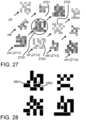
- the resulting clusters of dispersed dots (example: 210) are surrounded by non-active unprinted 211 space and are embodied by clusters of densely spaced horizontal and vertical segments possibly touching each other along part of their sides ( FIG. 28 , with touching locations 2801 hatched).
- the horizontal and vertical segments are made of active pixels (shown as black pixels).
- the clusters (e.g. 210) of densely spaced horizontal and vertical segments are located within the areas 110 of the corresponding juxtaposed clustered dots (compare FIG. 1 , 110 and FIG. 2 , 210 ).
- a fluorescent colorant is a fluorescent ink halftone or an overlay of fluorescent ink halftones that emits under UV illumination a given emission spectrum. Emission spectra are measured by illuminating the fluorescent sample with a UV light source and by capturing the emitted spectrum in the visible wavelength range with a spectrophotometer. The procedure is detailed in US Patent 8,085,438 , under Section "Measurement equipment, paper and printer”.
- a screen element defines the halftone space allocated to several colorants that together will form the desired printed color.
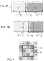
- the screen elements shown in FIGS. 3A, 3B and 4 (410) can simultaneously incorporate up to 3 printable colorants.
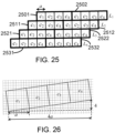
- the screen elements shown in FIGS. 24A, 24B, 24C and 25 can simultaneously incorporate 4 printable colorants.
- One screen element cell is associated to each printable colorant. Initially, screen element cells have all the same surface of 1 divided by the number of printable colorants that are simultaneously present within the screen element. Then, according to the surface coverages of the printable colorants, the screen element cells become larger or smaller.
- Such a screen element may incorporate three, four or more cells enabling having a single halftone made of three, four or more colorants.
- a juxtaposed screen element contains one bit per ink, e.g. bits 910, 911 and 912 in case of 3 fluorescent inks, e.g. blue, yellow-green and red. Such a bit, acting as an ink identifier, indicates the presence of the corresponding ink by being "active" or by being "printed".
- ink halftone separation or "ink halftone separation layer” designates a space in computer memory that contains information about the presence or absence of ink at each of its pixel positions.
- Active pixels indicate areas where, for rotogravure printing, cells are going to be engraved within the rotogravure cylinder.
- active pixels indicate areas of the print plate with the raised elements.
- active pixels indicate within the offset plate the locations of ink accepting areas.
- a pixel with a value of "1" designates the presence of the ink and an ink with a value of "0" the absence of the ink.
- the pixel with a "1" is an “active” or “printed” pixel and the pixel with a “0” is an "non-active", “inactive” or “unprinted” pixel.
- "active" pixels or pixel segments located in ink halftone separation memory are imaged onto the corresponding locations of the offset plate. After having inserted the offset plate into the offset press, its ink accepting locations attract the ink and transfer it onto the blanket. The blanket then transfers the ink onto the paper sheet. At the end of the printing process, the inked paper locations and areas correspond to the locations and areas of the active pixels or pixel segments located within the ink halftone separations that are present within the computer memory.
- a screen tile (e.g. FIG. 4 , 401 ) comprises one or several screen elements. Often, a screen tile has the shape of an obliquely oriented rectangle or parallelogram (e.g. FIG. 6 ) and replicates itself by using its sides as replication vectors.
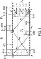
- a horizontal rectangular equivalent screen tile ( FIG. 7 or FIG. 8 , T 0 ) can be build, which contains the same information as in the original diagonally oriented rectangular or parallelogram screen tile. This equivalent horizontal rectangular screen tile replicates itself according to a horizontal vector ( FIG. 7 , w a ) and to an oblique vector ( FIG. 7 , w b ), see Section "Equivalent horizontal rectangular screen tiles".
- a screen element library is a library containing instances of a screen element or of a screen tile, with different entries corresponding to different surface coverages of the colorants present within the screen element or screen tile.
- the screen element library is accessed to read out a given pixel or a set of pixels located within a juxtaposed clustered or dispersed dot halftone.
- the pixel that is read contains the ink values, i.e., the presence or the absence of the contributing inks.
- the pixel read out acts as an ink identifier.
- a bitmap is a 2D array of pixels, with in general one byte per pixel, i.e. 8 bits per pixel.
- Binary bitmaps have 1 bit per pixel.
- Bitmaps can also be composed of 4 bits per pixel (nibbles).
- juxtaposed clustered dot halftoning method used for the generation of juxtaposed clustered dots incorporating simultaneously up to three colorants ( FIG. 4 ).
- the method can be extended to more colorants, see Section "Extension of juxtaposed dispersed dot halftoning to 4 or more colorant halftones".
- the exact position and area of a screen element cell associated to one colorant depends on the surface coverages of the other colorants.
- colorant cell C2 is positioned differently if the relative surface coverage of the neighboring colorant c 1 is small and the one of c 3 is large or vice-versa (compare FIGS. 3A and 3B ).
- Such a 3x3 juxtaposed dot cell array has the advantage that a cell of a given colorant (e.g. c 1 ) has as its two direct horizontal neighbors and as its two direct vertical neighbors the two other colorants (e.g. c 2 and c 3 ) .
- FIG. 5A shows the case s 1 '>1/3, s 2 ' ⁇ 1/3, and s 3 ' ⁇ 1/3, i.e. where the colorant surface ( s 1 ' -1/3) is spread out over neighboring cells c 2 and c 3 .
- the thickness h of the horizontal and vertical bands allowing to distribute the surface s 1 ' -1/3 from cell c 1 into horizontal and vertical neighboring cells c 2 and c 3 , according to the ratio of 1/3- s 2 ' and 1/3- s 3 '.
- 5A comprises the surfaces s 12 ' and s 13 ' representing respectively the part of surface ratio s 1 ' spilling out into cells c 2 and the part of it spilling out into cells c 3 .
- h 12 1 ⁇ 1 ⁇ s 1 + 2 s 2 ⁇ s 3 3
- h 13 1 ⁇ 1 ⁇ s 1 ⁇ s 2 + 2 s 3 3
- FIG. 5B shows the second case s 1 '>1/3, s 2 '>1/3, and s 3 ' ⁇ 1/3, where respective surfaces of both c 1 and c 2 spill out into cells c 3 .
- This juxtaposed screen dot cell growing strategy yields well clustered juxtaposed screen dots.
- clustered colorant surface layouts are computed according to ratios of their surface coverages by calculating how much individual colorants spread out into neighboring colorant cells.
- the layout of a colorant i larger than its initial cell size is formed by its colorant initial cell c i and by the bands h ij representing how much such a colorant spreads out into its neighboring colorant initial cells j .
- the unprinted black is restored between the juxtaposed colorant cells by scaling down each newly sized colorant cell ( FIG. 5A , c 1 , c 2 , c 3 ) so as to recover its desired original surface coverage.
- This scaling down operation is performed by fixing the location of the center of the cell and by multiplicatively scaling down the horizontal and vertical cell dimensions by the square root of the sum of the original surface coverages, i.e. by s 1 + s 2 + s 3 .
- the resulting colorant areas are scaled down by the sum of the original surface coverages. This scaling down operation ensures that the unprinted space is correctly placed around each colorant surface.
- the unprinted black surface is the surface between the screen cells, e.g. FIG. 24C , 2420.
- the resulting screen element may become part of the screen element library.
- the juxtaposed screen element library with n+1 different intensity levels for a juxtaposed screen element surface size n is constructed by iterating for colorant c 1 over surface coverages s 1 , from 0 to 1 in steps of 1/ n, for colorant c 2 , by iterating over surface coverages from 0 up to the value of 1- s 1 , and for colorant s 3 from 0 up to the value of 1- s 1 - s 2 (constraint: s 1 + s 2 + s 3 ⁇ 1).
- a program counting the number of all possible screen elements as a function of the number of intensity levels n+1 yields the number of screen elements that must be stored in the library.
- an oblique discrete tile such as an oblique discrete screen element as a horizontally laid out rectangular tile comprising the same number of pixels as the original oblique tile.
- Equation (5) states that v a is repeated f times and Vb is repeated g times in order to reach the same vertical position.
- d h gives the number of pixels horizontally after which the tile repeats itself. All values are integer values.
- vector w a replicates tile T 0 having vertices ABCD into its right adjacent tile T 1 whose left border is BC.
- Vector Wb replicates tile T 0 having vertices ABCD into the tile T 2 having the lower left corner E, i.e. e.g. pixel 810 is replicated into pixel 814.
- Vector w c w b - w a replicates tile T 1 into tile T 3 , i.e. corner B is replicated into corner E.
- the replication operation replicates the tile structure into its neighborhoods.
- the halftoning software module When traversing the pixels of the halftone image space, the program starts for example at pixel (1,1) within the halftone image space and at the same time at pixel (1,1) of the equivalent horizontal rectangular tile ( FIG. 8 , 810 ). The program follows the pixels of the halftone image and of the equivalent horizontal rectangular tile horizontally until it reaches the last pixel 811 of the equivalent rectangular tile. The horizontal vector attached to last pixel 811 specifies the next pixel location within the equivalent horizontal rectangular screen tile, in the present case pixel 810.
- the juxtaposed screen element library ( FIG. 9A ) is preferably constructed by creating a library of equivalent rectangular tiles, each one corresponding to certain surface coverages of the fluorescent colorants, to which corresponding ink halftones 905, 906, 907 are associated.
- three inks for example the fluorescent red, yellow-green, and blue inks
- the presence of three printable fluorescent inks are described by their identifiers, i.e. by the three bits embedded within a byte ( FIG 9B , 910, 911 and 912) or within a nibble (half a byte).
- Each equivalent rectangular tile has the size d h by d v and is formed by pixels ( FIG. 9B , e.g.
- Bit 901, 902, 904 having each one the size of one byte (or of one nibble).
- Bit 0 (910) of each byte can be understood as the bit identifying the fluorescent blue ink tile
- bit 1 (911) of each byte can be understood as the bit identifying the fluorescent yellow-green ink tile
- bit 2 (912) of each byte can be understood as the bit identifying the fluorescent red ink tile.
- bits 0, 1 and 2 are called "ink identifier bits” or "ink identifiers” and are associated to the current juxtaposed dispersed dot halftone pixel.
- the juxtaposed dispersed dot halftones are obtained by applying the dispersed dot halftoning procedure once for each contributing ink layer. This generates the juxtaposed dispersed colorant dot halftones with the ink identifier bits shown in FIG. 9B , 910, 911 and 912.
- the preferred dispersed dot halftoning procedure is the random threshold error diffusion procedure, which generates each time a different layout of the dispersed halftone.
- each of these clustered dots represents a colorant.
- the dispersed dot halftoning procedure applied on the juxtaposed clustered dots generates the corresponding juxtaposed dispersed dot halftones, with one bit per ink layer.
- the dispersed dot halftoning procedure is embodied by random threshold error diffusion, which generates for each ink layer that contributes to the colorants of the current screen element, an ink-specific cluster of densely spaced pixel segments.
- These ink-specific clusters of densely space pixel segments ( FIG. 12 , 1201, 1202 and 1203) are assembled into a screen element or screen tile forming the juxtaposed dispersed dot halftone ( FIG. 9B ).
- each pixel of such a halftone contains the ink identifier bits indicating the presence or absence of inks.
- FIG. 9A shows tiles 905, 906 and 907 representing different surface coverages of the fluorescent colorants.
- several bits (910, 911 or 912) of the same pixel e.g. 901 may be simultaneously activated.
- the ink identifier bits within the same pixel are activated.
- ink identifier bits of the blue ink tile and of the red ink tile may be activated (bits 910 and 912).
- white colorant which is composed by the overlay of the fluorescent blue, fluorescent yellow-green, and fluorescent red inks within the same tile pixel, ink identifier bits of the blue ink tile, of the yellow-green ink tile and of the blue ink tile may be activated (bits 910, 911 and 912).
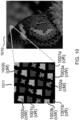
- FIG. 10 shows a software preview 1010 of an original color image printed by rotogravure and at the left side 1011 an enlargement of a region of the fluorescent color image 1010, with the corresponding simulated printed fluorescent colorant juxtaposed dispersed dots, where different gray tones represent different colorants. Due to its limited capabilities, this software preview only shows the clustered dots associated to different colorants. In real prints, dispersed dot halftones are present within the area of the clustered dots. Let us consider a halftone formed by the fluorescent red, magenta and white colorants. The red colorant (cR) appears in the diagonal rows 1001a, 1001b and 1001c. The magenta colorant (cM) appears in the diagonal rows 1002a and 1002b.
- the red colorant (cR) appears in the diagonal rows 1001a, 1001b and 1001c.
- the magenta colorant (cM) appears in the diagonal rows 1002a and 1002b.
- the white colorant (cW) appears in diagonal rows 1003a, 1003b and 1003c.
- the magenta colorant juxtaposed dots (1002a and 1002b) are formed by the overlay of the fluorescent blue and red ink-specific clusters of dispersed dot halftones.
- the white colorant juxtaposed dots (1003a, 1003b, 1003c) are formed by the overlay of the fluorescent blue, fluorescent yellow and fluorescent red ink-specific clusters of dispersed dot halftones.
- the red colorant (1001a, 1001b and 1001c) is identical with the fluorescent red ink cluster of dispersed dot halftone.
- FIG. 11 shows on the top 1100 the same simulated printed fluorescent colorant juxtaposed dispersed dots as in FIG. 10 , 1011.
- the fluorescent red colorant dots (cR) are marked as diagonals 1101a, 1101b, 1101c.
- the magenta colorant dots (cM) are marked as diagonals 1102a and 1102b.
- the white colorant dots (cW) are marked as diagonals 1103a, 1103b, 1103c.
- the bottom part of FIG. 11 shows the corresponding juxtaposed clustered dots separation layers, before applying dispersed dot halftoning: the fluorescent blue ink clustered dot separation layer 1115, the fluorescent yellow-green clustered dot ink separation layer 1116 and the fluorescent red clustered dot ink separation layer 1117.
- the blue ink separation layer 1115 is present within the colorant halftone dots of magenta and white. It appears therefore for fluorescent colorant magenta in columns 1112a, 1112b, and for fluorescent colorant white in columns 1113a, 1113b and 1113c of the blue ink separation layer 1115.
- the yellow-green separation layer 1116 is only present at the locations of the white colorant, i.e. the colorants dots 1113a, 1113b and 1113c.
- the red separation layer 1117 is present for the red, the magenta and the white colorants, i.e. all the colorants that appear in the halftone 1011 of FIG. 10 .
- FIG. 11 shows that there can be small as well as large juxtaposed clustered colorant dots.
- the juxtaposed clustered colorant dots of neighboring screen elements may touch each other.
- the simultaneous presence of large and small clustered dots would yield large and small gravure cells that create instability in the reproduction of the colors.
- rotogravure it is preferable to have fluorescent halftone dots of similar sizes.
- the requirement is therefore (a) to keep the juxtaposed approach ensuring that colorant dots are printed side by side, thereby avoiding quenching and shadowing effects and (b) to ensure that the juxtaposed clustered dots shown at the bottom of FIG. 11 are themselves halftoned as clusters of dispersed dots formed by dispersed segments which upon laser engraving yield gravure cells that are separated by walls.
- FIG. 12 shows the three ink separation layers 1201, 1202 and 1203 with their clusters of densely spaced pixel segments placed within the same space as the juxtaposed clustered dots from which they derive ( FIG. 11 , 1115, 1116, 1117 ) but in addition halftoned as juxtaposed dispersed dots.
- the blue dispersed halftone separation layer 1201 is derived from the clustered dot layer 1115 in FIG. 11 .
- the yellow-green (YG) dispersed halftone separation layer 1202 is derived from the clustered dot layer 1116 in FIG. 11 and the red dispersed halftone separation layer 1203 is derived from the clustered dot layer 1117 in FIG. 11 . Note that the active dispersed pixel segments shown in FIG. 12 and FIG.
- the dispersed dot ink halftone separations shown in FIG. 12 are generated as follows.
- the juxtaposed clustered dot ink halftones are considered to be gray scale images, with the black dots being subjected to a reduction in ink level expressed by an ink level reduction factor ( r d ) used for dispersed halftoning.
- r d ink level reduction factor
- These gray dots have exactly the same layout as the clustered dots shown in FIG. 11 , bottom, but instead of having an ink level of 1 (totally black), they have an ink level of 0.6 .
- these juxtaposed ink level reduced gray clustered dots are halftoned with a halftoning algorithm yielding dispersed dots, preferably a variant of error-diffusion. This yields the dispersed dot halftone ink separations of FIG. 12 .
- An efficient implementation consists in generating for each ink layer a separate dispersed dot layer with a dispersed dot halftone at the correct ink level reduction, e.g. 60%.
- This separate halftone layer is generated from a uniform layer at 60% ink level by an error-diffusion procedure, working at a pixel resolution that corresponds to the required size of the rotogravure cells.
- this separate halftone layer there is on average 60% of active pixels (shown in the figures as black pixels). For example, one may work at a resolution of 1024 dpi, yielding pixels of size 24.8 ⁇ m. Other resolutions are also possible, depending on the type of the considered rotogravure printer.
- the resulting separate dispersed dot structure is resampled to the resolution that was used for juxtaposed clustered dot halftoning. Then, a logical "AND" is performed between the juxtaposed clustered dot ink separation layer and the separate dispersed dot ink level reduced halftone layer. This yields the juxtaposed dispersed dot ink separation layers of FIG. 12 that are used for creating for example by laser engraving the cells of the rotogravure cylinder.
- dispersed halftone ink level reduction factors generate different juxtaposed dispersed dot halftones. For example; with an ink level reduction factor of 40%, the dispersed dot halftone, within its cluster, comprises only 40% of black pixels, see FIG. 14 .
- the dispersed halftone ink level reduction factor r d is obtained by the multiplication of a rotogravure reduction factor r g and a fluorescence reduction factor r f .
- the rotogravure reduction factor r g expresses the fact that a printed solid ink layer is obtained by rotogravure cells that cover only a part of the full surface.
- the rotogravure printing process requires walls between neighboring rotogravure cells that are engraved into a rotogravure cylinder.
- the black (active) pixels in FIG. 12 or FIG. 14 indicate the locations of the rotogravure cells. These cells are bordered by side walls, represented by white (non-active) pixels.
- the fluorescence reduction factor is necessary in case of a fluorescent invisible ink having a stronger fluorescence, compared with the other fluorescent inks.
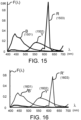
- FIG. 15 shows without fluorescent reduction the emission spectra of printed full-tone fluorescent inks obtained with a rotogravure reduction factor of 60% for each fluorescent ink (fluo blue ink: 1501, fluo yellow-green ink 1502 and fluo red ink 1503).
- the emission spectrum of the red fluorescent ink is much higher than the emission spectra of the other blue and yellow-green fluorescent inks. Therefore, it needs to be reduced by an appropriate fluorescence reduction factor.
- This factor is obtained by fitting it with a fluorescent color prediction model in order to obtain for the overlay of the three fluo red, yellow-green and blue ink dispersed halftones, all printed with the 60% rotogravure reduction factor, the white colorant, i.e. a colorant with a high CIELAB L* value and close to zero a * and b* values.
- the blue fluorescence reduction factor is 85%.
- the resulting emission spectra are shown in FIG. 16 with the fluorescent blue ink 1601, the fluorescent yellow-green ink 1602 and the fluorescent red ink 1603.
- the dispersed halftone ink level reduction factor is the multiplication of the rotogravure reduction factor and a fluorescence reduction factor
- the dispersed halftone ink level reduction factor comprises only the rotogravure reduction factor and is therefore 60%.
- different ink level reduction factors can be applied for dispersed halftoning of different fluorescent ink layers ensures the creation of colorants having optimal gray and white tones.
- on may directly build the screen element library with the juxtaposed dispersed dot colorant halftones by storing them according to their surface coverages after having applied dispersed dot halftoning to the generated juxtaposed clustered dot halftones.
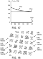
- the dispersed halftone ink level reduction factor at 100% surface coverage is 50% (1704) and at small input surface coverages, the dispersed halftone ink level reduction factor is between 60% and 70%.
- the dispersed halftone in level reduction curve 1703 shows that at small nominal input surface coverages, the dispersed halftone ink level reduction factors are less pronounced than at large nominal input surface coverages.
- This reproduction curve can be established for example by printing at 10%, 25% and 50% white colorant surface coverages a number of patches with dispersed halftone ink level reduction factors associated to each of the inks varying in small steps and select the dispersed halftone ink level reduction factors that yield the best gray values, either measured as emission spectra and converted to CIELAB or estimated by having an observer viewing the corresponding patches under UV.
- the special error diffusion technique aims at creating juxtaposed dispersed dot colorant halftones by overlays of ink-specific clusters of dispersed pixel segments ( FIG. 12 , 1201 for the blue ink, 1202 for the yellow-green ink and 1203 for the red ink), which are, within the area of the corresponding juxtaposed clustered colorant dots, partly overlapping and partly non-overlapping ( FIG. 27 ).
- This is achieved by a modified error diffusion algorithm called "random threshold error diffusion”. This algorithm ensures that halftones having the same surface coverages are halftoned each time differently thanks to a random threshold generator.
- the juxtaposed clustered dots of FIG. 11 , 1125, 1126 and 1127 have exactly the same spatial layout.
- the resulting dispersed "YG" halftones shown in FIG. 12 , 1205, 1206 and 1207 have all different layouts of the dispersed dot halftone.
- the randomness in dispersed dot halftone layout ensures that the overlay of multiple ink halftones for printing with fluorescent colorants does not result in undesired moirés.
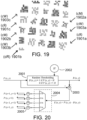
- enlargement 1011 we show in FIG. 18 the overlay of the fluorescent blue (halftone 1201) and red (halftone 1203) ink halftone layers.
- the locations of the fluorescent red colorant dots "cR" are marked as 1801a, 1801b, 1801c
- the locations of the magenta colorant dots "cM” are marked 1802a and 1802b
- the locations of the white colorant dots "cW” are marked as 1803a, 1803b, 1803c.
- the red colorant present in diagonals 1801a, 1801b or 1801c, there is only the red ink dispersed halftone. It is represented by a positively oriented diagonal hatching.
- the magenta colorant "cM” present in diagonals 1802a and 1802b both the red ink halftone and the blue ink halftone are present.
- the blue ink halftone is represented by a negatively oriented diagonal hatching.
- FIG. 19 shows the same halftone patch as in FIG. 11 , 1100 with all overlaid ink halftone separation layers.
- the presence of the yellow-green ink is marked by a dot pattern array.
- the white colorant "cW" (1903a, 1903b, 1903c) one can verify that some of the pixels remain unprinted, some are printed by one ink (positive diagonals, negative diagonals or dot array), some are printed by two inks (two types of diagonals or one type of diagonals and dot array) and some are printed by three inks (two types of diagonals and one dot array).
- the random-thresholding error diffusion procedure that produces the juxtaposed dispersed dot ink halftones shown above and in FIGS. 12, 14 , 18 and 19 is illustrated in FIG. 20 .
- It comprises a random threshold generator 2002 that generates the threshold H that is used for the decision 2001 if a pixel needs to be activated (e.g. pixel to be set to "1" representing a black pixel) or needs to be deactivated (e.g. pixel to be set to "0", representing a white pixel).
- the error computation step 2003 calculates the error which is the difference E ( x,y ) between the normalized input pixel ink level value P ( x,y ) and the output ink level value B ( x,y ) which is zero (deactivated) or one (activated).
- the error distribution step 2004 distributes the error to the direct and indirect neighbor pixels which have not yet been processed. In order to compensate for the error, each of these neighboring pixels adds its fraction of the received error to its current ink level.
- neighbor pixels P ( x +1, y +1), P ( x,y+ 1) , P ( x- 1 ,y +1) , and P ( x+ 1,y) receive fractions 1/16, 5/16, 3/16 and 7/16, respectively, of the error E ( x,y ) .
- Good results have been obtained with a generated random threshold H uniformly distributed in the interval between 0.1 and 0.9 . Other intervals are also possible, e.g. 0.2 to 0.8 or 0.3 to 0.7.
- Formula (16) predicts the emission spectrum F h ( ⁇ ) of a halftone formed by a number m colorants whose full tone emission spectra F i ( ⁇ ) have been measured.
- the ink spreading curves mapping nominal to effective surface coverages of the colorants are obtained by applying formula (16) separately to each single colorant and for different nominal surface coverages, e.g. 0.25, 0.5, and 0.75 .
- the corresponding effective surface coverages are fitted by minimization of a difference metric between predicted emission spectrum and measured emission spectrum.
- a possible difference metric is the square of the Euclidian distance between the two spectra, expressed as vectors with discrete spectral components (e.g. 400nm to 700nm in steps of 10nm).
- Exponent n is obtained by predicting according to formula (16) the emission spectra of halftones at combinations of zero, 0.5 and fulltone colorant surface coverages. A value of n is selected that minimizes over the considered samples a difference metric between the predicted and the measured emission spectra.
- Fluorescent emission spectra predicted according to formula (16) are converted to CIE-XYZ colorimetric values and then to CIELAB, see for example US Patent 8,085,438 to Hersch et al.
- the resulting colorimetric CIELAB values express the predicted fluorescent color.
- Fluorescent emission prediction by mapping nominal to effective surface coverages of the colorants and by applying formula (16), followed by the calculation of the corresponding fluorescent emission color by conversion to CIE-XYZ and then to CIELAB forms the color prediction model. It maps nominal surface coverages of the fluorescent colorants to CIELAB colors.
- a desired CIELAB color located within the fluorescent color gamut can be obtained by using this color prediction model to fit the nominal surface coverages of the considered colorants. When printed as halftones, the fitted surface coverages will yield under UV illumination the desired CIELAB color.
- Constructing the fluorescent emission gamut is carried out by considering many possible combinations of surface coverages of the selected colorants.
- the gamut is formed by many possible combinations of surface coverages of the three colorants selected from the 5 available colorants.
- juxtaposed halftone dots comprising up to four colorants FIGS. 24A, 24C and 25
- the gamut is formed by many possible combinations of surface coverages of the four colorants selected from the available colorants.
- the possibly non-convex gamut boundary is obtained by first performing a Delaunay tetrahedrization of the predicted CIELAB color points and then by computing with the Ball-Pivoting algorithm the set of surface triangles defining the possibly concave gamut boundary.
- the Ball Pivoting algorithm is described in the publication by F. Bernardini, J. Mittleman, H. Rushmeier, C. Silva, and G. Taubin, The Ball-Pivoting Algorithm for Surface Reconstruction, IEEE Trans. Visualization and Computer Graphics, Vol. 5, No. 4, pp. 349-359 (1999 ).
- the gamut formed by input image colors should also be created.
- Most RGB color images are specified in a display color coordinate system such as the standard sRGB display color coordinate system.
- sRGB gamut is created by considering all combinations of sRGB red, green and blue values from 0 to 1, e.g. in steps of 0.02 yielding in total 132'651 colors.
- These sRGB colors are converted to CIE-XYZ and then to CIELAB colorimetric values, as known in the art.
- the sRGB gamut is formed in the CIELAB space by the convex hull of these color values.
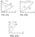
- FIGS. 21A, 21B and 21C show in the CIELAB 3D space lightness-chroma (L*C*) slices through the fluorescent emission gamut G f (2111, 2112, 2113) and through the sRGB gamut G RGB (2101, 2102, 2103).
- FIG. 21A shows a slice at the hue angle of zero degrees, with the chroma axis C* being the a * axis.
- FIG. 21B shows another L*C* slice at the hue angle of 120 degrees.
- FIG. 21C shows a further L*C* slice at the hue angle of 240 degrees.
- the goal is to reproduce as invisible fluorescent images viewable under UV light the colors present in classical digital images, such as the images acquired by digital or smartphone cameras.
- gamut mapping i.e. we map colors present in the sRGB gamut into colors present in the fluorescent emission gamut. This ensures that classical digital images can be printed as invisible fluorescent images and viewed under UV illumination as fluorescent emission color images.
- gamut mapping we map the colors present in the sRGB gamut G rgb into the fluorescent emission gamut G f according to the following rules.
- FIG. 22 shows schematically a lightness-chroma slice through both the sRGB ( G rgb ) and the fluorescent emission ( G f ) gamuts at the hue angle h 0 of the currently considered input color.
- the preferred gamut mapping method consists in considering the sub-gamut of the sRGB gamut described by the J rgb interval and bordered by the G rgb and the G fs boundaries, named [ G rgb , G fs ]. This sRGB sub-gamut is mapped into the fluorescent emission sub-gamut described by the J f interval and bordered by the boundaries of the G f gamut and of the G fs sub-gamut.
- This sub-gamut is named [ G f , G fs ].
- sRGB colors on the sRGB interval 2201_2203 are mapped onto colors on the fluorescent emission interval 2202_2203.
- sRGB colors on the sRGB interval 2211_2213 are mapped onto colors of the fluorescent emission interval 2212_2213. If no lightness mapping occurs, display sRGB colors located within the G fs gamut boundaries remain at their original LAB coordinate. If lightness mapping occurs, only their lightness values change.
- each sRGB color mapped into the fluorescent gamut is located within a tetrahedron.
- the goal is to represent the current sRGB color by a fluorescent halftone color.
- the colorant surface coverages associated to the current sRGB value are obtained by a linear combination (also known as barycentric interpolation) of the surface coverages of the colorants forming the tetrahedron's vertices, as known in the art (see I. Amidror, Scattered data interpolation methods for electronic imaging systems: a survey, Journal of Electronic Imaging Vol 11, No 2, pp. 157-176, April 2002 ). These colorant surface coverages are inserted into the table mapping sRGB values to nominal colorant surface coverages.
- s i ' stands for s 1 ' , s 2 ' , s 3 ' , s 4 '
- s i stands for s 1 , s 2 , s 3 , s 4 .
- the juxtaposed screen element length 4 a into segments of length given by the colorant surface ratio s 1 ' , s 2 ' , s 3 ' , s 4 ' see FIG. 24B . Then, in order to restore the black area between the colorants, the areas of the colorant rectangles are spatially scaled down by s 1 + s 2 + s 3 +s 4 or, equivalently, their horizontal and vertical sides are scaled down by s 1 + s 2 + s 3 + s 4 and they are positioned centrally. As example, FIG.
- the scaled down rectangles define the layout of the corresponding juxtaposed clustered colorant dots.
- juxtaposed screen elements are laid out by placing them side by side along the line of juxtaposed screen elements, e.g. FIG. 25 , 2501 and 2502.
- Vertically adjacent lines of juxtaposed screen elements e.g. L 1 and L 2
- L 1 and L 2 are created by shifting each vertically adjacent screen element line by one initial cell of the screen element ( FIG. 25 , 2511, 2521).
- the base tile comprises cells c 1 , c 2 and c 3 .
- the preparation phase comprises the creation of the table mapping sRGB values to juxtaposed surface coverages of the colorants. It also comprises the creation of the juxtaposed clustered or dispersed dot screen element library.
- the preparation phase is generally needed once for a given printing environment comprising the selected inks, the selected additional colorants, as well as the printer dependent elements such as the gravure cylinder, the engraving technology and the rotogravure printer.
- a printing session comprises within the output halftone space the creation of the target halftone ink separations that serve for engraving the cylinders, for imaging the offset plate, for creating the latent image on the photoconductor or, in case of ink-jet, for directly printing the target halftone ink separations on paper.
- the target halftone output space is scanned pixel by pixel and scanline by scanline.
- the corresponding location in the input image is found and its color, called input color, is read.
- Corresponding colorant surface coverages are obtained from the table mapping sRGB values to juxtaposed surface coverages of the colorants.
- the corresponding entry in the juxtaposed dispersed dot screen library is accessed and, according to the current location in the halftone space, the pixel from the library is read out and its ink identifier bits placed onto the output ink halftone separations used for engraving the rotogravure cylinders, for imaging the offset plates, for creating the latent image on the photoconductor (electrophotography) or for printing on paper (inkjet).
- an additional step consists in applying dispersed dot halftoning before placing the pixel ink identifier bits resulting from dispersed dot halftoning onto the output ink halftone separations.
- the method steps to be executed or equivalently the actions to be performed are either part of the preparation phase or of the target ink separation halftoning phase. Since the steps of the preparation phase are carried out unfrequently, their execution time is not critical.
- the ink separation halftoning phase is executed each time a set of new pages needs to be printed. Its execution time is therefore critical.
- each preparation task P1, P2, P3, P4 and P5 as well as each halftoning task T1, T2, T3, T4 and T5 will be programmed as a specific software module.
- These software modules are executed on a computing system comprising at least one CPU, memory, mass storage and network connections to external devices such as the rotogravure cylinder engraving apparatus. The software modules are executed in the sequence described above.
- Juxtaposed dispersed colorant dot halftones are characterized by diagonally laid out clusters of dispersed dots, surrounded by unprinted space (e.g. FIG. 27 , 2701).
- FIG. 27 shows schematically arrangements of diagonally oriented clusters (e.g. 2720) of dispersed colorant dot halftones.
- FIG. 27 is an enlarged instance of the halftone representation of FIG. 19 .
- the diagonals of colorant clusters named "cW" represent the fluorescent white colorant made of the overlays of the fluorescent blue, yellow-green and red clusters of dispersed dot halftones.
- the diagonals of dispersed colorant clusters named "cM” represent the fluorescent magenta colorant made of the overlays of the fluorescent blue and red clusters of dispersed dot halftones.
- the diagonals of dispersed colorant clusters named “cR” represent the fluorescent red colorant made of the fluorescent red clusters of dispersed fluorescent red ink halftones. Clusters of dispersed dots are laid out diagonally. Each diagonal line of clusters represents a specific colorant.
- the diagonals appear in the sequence of a first colorant (e.g cW 2711), a second colorant (cR 2712), a third colorant (cM 2713), and again the same sequence of first (cW 2714), second and third colorants, and so on, repeated as long as there is no change in the selected colorants.
- a first colorant e.g cW 2711
- cR 2712 a second colorant
- cM 2713 third colorant
- each cluster of dispersed dots of a given ink layer separation e.g. the red colorant "cR"
- there are small "white” non-active areas representing pixels (e.g. 2702, 2703) that are part of the boundaries between the "black” active pixels.
- the "black” active pixels (or equivalently pixel segments) specify the places of (a) gravure cells to be engraved onto the rotogravure cylinder, (b) ink accepting areas on the offset plate, (c) locations on the photoconductor that will attract toner particles or (d) printed locations on paper (inkjet).
- An ink halftone separation is transferred into a device used for printing, such as a rotogravure cylinder, a gravure plate, an offset plate, a photoconductor or a flexography plate. Once transferred into such a device, the ink halftone separation is also called "device halftone separation".
- An engraved rotogravure cylinder for example obtained by laser engraving, is associated to a given ink halftone separation. Its engraved small cells have the same layout as the black pixels shown in FIG. 12 .
- the fluorescent blue color separation cylinder has the layout shown in 1201, the yellow-green color separation cylinder the layout shown in 1202 and the red color separation cylinder the layout shown in 1203, for the colorants shown in FIG. 10 , enlargement 1011.
- Most gravure cells engraved according to the present disclosure are thin (1 pixel width) and have a lengthy shape, of 1 to several pixels, see examples in FIG. 12 and FIG. 14 . Neighboring engraved cells may touch each other, either by their corners, or by a part of their side.
- FIG. 28 shows junctions (hatched) between neighboring cells. In that example, touching sides are one pixel long.
- a fluorescent color halftone image printed by rotogravure with cylinders engraved according to the present disclosure, with clusters of densely spaced small cells laid out along diagonals shows a succession of diagonally laid out clusters, with neighboring cluster diagonals being associated to different colorants, as shown in FIG. 11 , 1100.
- juxtaposed dispersed dot ink separations show successions of clusters of densely spaced pixel segments (e.g. 1214, 1215, 1216) having similar sizes along sections of a same diagonal, e.g. the clusters shown in the diagonal 1212 ( FIG. 12 ).
- the successions of clusters of densely spaced dispersed segments have also a similar size. Their size however generally differs from the size of the clusters located on the neighboring diagonal. This can be verified by comparing the cluster size in diagonal 1212 with the cluster size in diagonal 1213.
- the characterization of the juxtaposed dispersed dot halftones on rotogravure cylinders is also valid for characterizing offset plates: the ink accepting areas of the offset plates have the same layout as the juxtaposed dispersed dot ink halftone separations shown in FIG. 12 .
- the latent images produced on the photoconductor have also the same layout as the juxtaposed dispersed dot ink halftone separations shown in FIG. 12 .
- the juxtaposed dispersed dot halftones also enable characterizing a print obtained by inkjet.
- a main application is the creation of invisible color images viewable under UV light for the protection of security documents such as bank notes, passports, ID cards, fiscal stamps, entry tickets, travel documents, checks, vouchers or valuable business documents.
- security documents such as bank notes, passports, ID cards, fiscal stamps, entry tickets, travel documents, checks, vouchers or valuable business documents.
- a further application is the protection of valuable articles such as software packages and medical drugs.
- Further applications may combine decorative and protective aspects such as wine bottles, perfumes, watches, fashion articles, vehicles and clothes. Further applications are mainly decorative such as commercial art, publicity displays, fashion articles, and night life, where digitally produced fluorescent images viewed under UV illumination in the dark have a strong appealing effect.
- the corresponding valuable item is considered to be authentic. If this is not the case, the corresponding valuable item is to be considered as a counterfeit.
- the corresponding valuable item is to be considered as a counterfeit.
- Such a comparison can be carried out with by a computer program which computes a distance metric between the two color images. If the distance metric between the colorant halftone color image and the fluorescent" RGB image is small, the valuable item is considered to be authentic. If the distance metric is large, the valuable item is considered to a counterfeit.
- a further means of authenticating a valuable item consists in comparing original ink halftone separations formed by clusters of juxtaposed densely spaced pixel segments located in a computer's memory with corresponding device halftone separations present on the device which is part of the printing system with which the valuable item is printed.
- Such devices comprise rotogravure cylinders, gravure plates, offset plates and flexography plates.
- the corresponding valuable item is considered to be authentic and in case they are dissimilar, the corresponding valuable item is considered to be a counterfeit. Similarity is tested by checking on both the original ink halftone separations and on the corresponding device halftone separations the presence of features selected from the list of characteristic features.
- Some characteristic features may be invisible at some locations of an ink halftone separation. For example, if the surface coverages of one of the colorants is very large, no other colorant is present, and the unprinted space is very small, then there is only a single colorant per screen element. In that specific case, features (a), (c) and (e) are not applicable. As another example, consider an ink halftone separation transferred onto a device for printing (e.g. a rotogravure cylinder or an offset plate). Since the resulting device halftone separation is associated with a single ink only, features (a), (c) and (e) are not applicable.
- a device for printing e.g. a rotogravure cylinder or an offset plate
- Juxtaposed dispersed dot halftoning is also applicable in order to create ink halftone separations for offset printing.
- the dispersed halftone ink level reduction factors associated to the ink halftones enable controlling the density or, equivalently, the amount and areas of horizontal, vertical and diagonal pixel segments located within the clusters of dispersed dots. This enables tuning the intensity of the emitted fluorescence of each fluorescent offset ink.
- Juxtaposed clusters of dispersed dot halftones such as those shown in FIGS. 2 , 12 , 14 and 28 can directly be used to create the plate for offset printing. Therefore, juxtaposed dispersed dot halftoning is also appropriate for offset printing of fluorescent images viewable under UV light.
- the arguments stated above in respect to offset and inkjet printing also apply to electrophotography, especially liquid toner electrophotography.
- the dispersed halftone ink level reduction factors also enable controlling the density of individual toners, thereby tuning their emitted fluorescent intensity.
- Juxtaposed dispersed dot halftones such as those shown in FIGS. 2 , 12 , 14 and 28 can directly be used to create the latent image on the photoconductor.
- a further use case concerns the deposition of various materials, e.g. materials dissolved in a solution, viscous materials, biomaterials, conducting materials, non-conducting materials, magnetic materials, specularly reflecting materials, iridescent materials, plastic materials, opaque inks, metallic inks.
- Such liquids, inks or viscous materials can be solidified by evaporation, by lowering or increasing the temperature, by UV radiation, by visible light radiation, by heating or by chemical reactions.
- Such liquids or viscous materials can be deposited on a substrate by gravure printing, by pad printing or by ink-jet. Therefore, the presently disclosed juxtaposed dispersed dot halftoning method is applicable.
- rotogravure prints obtained with juxtaposed dispersed dot halftoning show that individual colorants are printed side by side and are surrounded by unprinted space (black space in FIG. 11 , 1100 ). This proves that the corresponding documents or valuable articles are authentic.
- the presence of the juxtaposed dispersed dot halftones ( FIG. 12, FIG. 14 ) on the gravure cylinders indicates the presence of a rotogravure print setup operable for printing documents or valuable articles incorporating counterfeit prevention features.
- non-standard fluorescent inks such as the yellow-green ink ( FIG. 15 , 1502 ) makes color separation with standard software packages a very difficult task.
- the proposed fluorescent color reproduction framework described in the present disclosure supports the reproduction with such non-standard fluorescent inks thanks to its spectral emission measurements, its spectral prediction of fluorescent prints, its gamut mapping and its juxtaposed dispersed dot halftoning method.
- juxtaposed dispersed dot halftoning provides a balanced fluorescent halftone fading behavior, which exhibits less hue shift than classical clustered dot halftones.
- the juxtaposed dispersed dot halftoning can be extended to 4 or more colorants by simply forming a screen element with additional cells, as shown in FIG. 24A for the case of 4 cells.
- the ratios of the surface coverages of the colorants enables placing the successive cells ( FIG. 24B ).
- the produced screen element tiles the plane by displacing each successive row of screen elements by one initial screen cell of width a ( FIG. 25 ).
Landscapes
- Engineering & Computer Science (AREA)
- Multimedia (AREA)
- Signal Processing (AREA)
- Textile Engineering (AREA)
- Printing Methods (AREA)
Claims (13)
- Ein Verfahren zur Herstellung von authentifizierbaren Farbrasterdrucken die aus nebeneinander angeordneten Clustern von verteilten Punkten bestehen, umfassend die Schritte:- Erstellen eines Rasterelements mit nebeneinander angeordneten Clusterpunkten (FIG. 11, 1115 'B', 1116 'YG', 1117 'R'), wobei die Flächen der nebeneinander angeordneten Clusterpunkte durch die Flächenabdeckungen von im Rasterelement vorhandenen Farbstoffen bestimmt werden;- Erzeugen der nebeneinander angeordneten Cluster von verteilten Punkten (FIG. 12) durch ein Rasterverfahren mit verteilten Punkten, das auf die nebeneinander angeordneten Clusterpunkte (FIG. 11, unten) angewendet wird, wobei die nebeneinander angeordneten Cluster von verteilten Punkten aus Sätzen von dicht beabstandeten Segmenten (FIG. 12, 1214, 1215, 1216) bestehen, die teilweise oder vollständig von nicht druckbaren Grenzen innerhalb der Bereiche der nebeneinander angeordneten Clusterpunkte umschlossen sind;- Anpassen des Rasterverfahrens mit verteilten Punkten durch Definition von Tintenreduktionsfaktoren (FIG. 17), die die Flächenverhältnisse der Segmente innerhalb der Sätze von dicht beabstandeten Segmenten festlegen;- Drucken der nebeneinander angeordneten Cluster von verteilten Punkten durch Übertragung auf einen Farbdrucker; wobei:-- für einen Workflow mit fluoreszierender Farbwiedergabe die Tintenreduktionsfaktoren (FIG. 17) optimiert werden, um unter UV-Licht fluoreszierende achromatische Grautöne und Weißtöne zu erzielen,-- die Authentifizierung der authentifizierbaren Farbrasterdrucke durch Überprüfung der Anwesenheit charakteristischer Merkmale der nebeneinander angeordneten Cluster von verteilten Punkten erfolgt.
- Das Verfahren nach Anspruch 1, wobei das Rasterverfahren mit verteilten Punkten ein Fehlerdiffusionsverfahren (FIG. 20) ist, dessen Schwellenwerte (2001, 'H') zufällig verteilt sind, wodurch sichergestellt wird, dass jede Instanz der Sätze von dicht beabstandeten Segmenten ein unterschiedliches Layout aufweist (FIG. 14, 1410, 1411, 1412), wobei die unterschiedlichen Layouts es ermöglichen, die Farbstoffe durch Überlagerung der Sätze dicht beabstandeter Segmente zu erzeugen, die verschiedenen Druckfarben zugeordnet sind (FIG. 18, "cM", 1802a), wodurch unerwünschte lokale Moiré-Effekte vermieden und Positionsungenauigkeiten der Sätze von dicht beabstandeten Segmenten toleriert werden, ohne Farbabweichungen zu verursachen.
- Das Verfahren nach Anspruch 1, bei dem die Positionen und Flächen der Segmente die Positionen und Flächen angeben, an denen:- für den Tiefdruck ein Tiefdruckzylinder graviert wird,- für den Tampondruck eine Tampon-Tiefdruckplatte graviert wird,- für den Offsetdruck die Segmente auf die Offsetplatte abgebildet werden,- für die Elektrofotografie die Segmente auf den Photoleiter abgebildet werden,- für den Flexodruck erhabene Elemente auf der Flexodruckplatte vorhanden sind, und- für den Tintenstrahldruck Tinte aufgetragen wird;wobei im Fall des Tiefdrucks die Gravuren Tinten tragen, die auf das Substrat der authentifizierbaren Farbrasterdrucke übertragen werden.
- Das Verfahren nach Anspruch 1, bei dem das Erstellen des Rasterelements mit den nebeneinander angeordneten Clusterpunkten die folgenden Schritte umfasst:(a) Auswählen der Farbstoffe, die im Rasterelement platziert werden sollen;(b) Auslegen des Rasterelements (FIG. 4, FIG. 6);(c) Berechnen der Verhältnisse der Flächenabdeckungen der Farbstoffe;(d) Dimensionieren der Farbstoffzellen, die den Farbstoffen zugeordnet sind, entsprechend den Verhältnissen der Flächenabdeckungen (FIG. 3A, FIG. 3B); und(e) Skalieren der Farbstoffzellen durch einen Flächenreduktionsfaktor, der einer Summation der Flächenabdeckungen der Farbstoffe entspricht;wobei die Schritte (c), (d) und (e) einen nicht druckbaren Bereich (FIG. 11, 1115, 1116, 1117) schaffen, der die nebeneinander angeordneten Clusterpunkte umgibt.
- Das Verfahren nach Anspruch 1, bei dem das Erstellen der authentifizierbaren Farbrasterdrucke Teil eines fluoreszierenden Farbwiedergabe-Workflows ist, um innerhalb eines Ausgaberasterraums Tintenrastertrennungen mit fluoreszierenden Tinten (FIG. 15) zu erzeugen, wobei der Workflow die folgenden Schritte umfasst:(a) Auswählen eines Eingabefarbbilds;(b) Scannen des Ausgaberasterraums Pixel für Pixel und Zeile für Zeile;(c) Bestimmen der entsprechenden Positionen im ausgewählten Eingabebild;(d) Abrufen der Bildfarben an den entsprechenden Positionen;(e) Zugreifen auf eine zuvor erstellte Tabelle, die die Bildfarben auf Flächenabdeckungen der durch die fluoreszierenden Tinten und ihre Überlagerungen gebildeten Farbstoffe abbildet;(f) Abrufen der Flächenabdeckungen der Farbstoffe aus der zuvor erstellten Tabelle;(g) Erhalten eines nebeneinander angeordneten Rasters mit verteilten Punkten (FIG. 9B) durch Zugriff auf eine Rasterelementbibliothek entsprechend den Flächenabdeckungen der Farbstoffe;(h) Aus dem nebeneinander angeordneten Raster mit verteilten Punkten Lesen der Identifikatoren der fluoreszierenden Tinten (FIG. 9B, 910, 911, 912); und(i) Kopieren der Identifikatoren der fluoreszierenden Tinten auf die Tintenrastertrennungen; wobei:- die Tintenrastertrennungen die Sätze von dicht beabstandeten Segmenten enthalten, die die Positionen und Flächen des Drucks angeben, an denen die fluoreszierenden Tinten aufgetragen werden (FIG. 28), und- in Bezug auf Fälschungsschutz die durch die fluoreszierenden Tinten gebildeten authentifizierbaren Farbrasterdrucke nur unter UV-Licht sichtbar sind (FIG. 10, 1010, 1011) und daher schwer zu fälschen sind.
- Verfahren nach Anspruch 5, wobei die Rasterelementbibliothek eine Bibliothek von nebeneinander angeordneten Rasterpunkt-Halbtönen (FIG. 11, 1115, 1116, 1117) ist, und wobei der nebeneinander angeordnete Rasterpunkt-Halbton (FIG. 12) durch Zugriff auf die Bibliothek von nebeneinander angeordneten Rasterpunkt-Halbtönen und durch Anwendung des Rasterpunkt-Verfahrens auf die nebeneinander angeordneten Rasterpunkte erhalten wird.
- Ein authentifizierbarer Farbrasterdruck (FIG. 10, 1010, FIG. 11, 1100), der von einem Druckgerät erzeugt wird, wobei der Druck als charakteristische Merkmale Tintenraster aufweist, die nebeneinander angeordnete Cluster von dicht beabstandeten Segmenten bilden, wobei jedes Segment teilweise oder vollständig von unbedruckten Grenzen umgeben ist (FIG. 28, 2802), und wobei der Druck durch Senden der nebeneinander angeordneten Cluster von dicht beabstandeten Segmenten an das Druckgerät erfolgt, und wobei:- die nebeneinander angeordneten Cluster von dicht beabstandeten Segmenten von unbedrucktem Raum umgeben sind (FIG. 27, 2701),- die nebeneinander angeordneten Cluster von dicht beabstandeten Segmenten schräg entlang der Diagonalen angeordnet sind (FIG. 14, 1410, 1411, 1412),- die Diagonalen der nebeneinander angeordneten Cluster von dicht beabstandeten Segmenten, die zu verschiedenen Farbstoffen gehören, dieselbe schräge Ausrichtung aufweisen (FIG. 12, 1201 'B', 1202 'YG', 1203 'R'),- die nebeneinander angeordneten Cluster von dicht beabstandeten Segmenten, die zu verschiedenen Farbstoffen gehören, sich nicht überlappen (FIG. 11, 1100),- die nebeneinander angeordneten Cluster von dicht beabstandeten Segmenten auf benachbarten Diagonalen zu unterschiedlichen Farbstoffen gehören (FIG. 11, 1100),- aufeinanderfolgende nebeneinander angeordnete Cluster von dicht beabstandeten Segmenten innerhalb derselben Diagonale ähnliche Größen aufweisen (FIG. 11, 1100), und- die Authentifizierung mit einer RGB-Kamera durchgeführt wird, die ein Bild der genannten Tintenraster aufnimmt und auf glatten Bildbereichen überprüft, ob die genannten charakteristischen Merkmale (FIG. 11, 1100) vorhanden sind.
- Der authentifizierbarer Farbrasterdruck nach Anspruch 7, der mit einem Gerät gedruckt wird, das aus der Gruppe der Tiefdrucker, Tampondrucker, Offsetdrucker, Flexodrucker, elektrofotografischen Drucker und Tintenstrahldrucker ausgewählt ist, wobei die Tinten-Halbtöne unter UV-Beleuchtung die nebeneinander angeordnete Cluster dicht beabstandeter Segmente aufweisen, die fluoreszierend sind.
- Der authentifizierbarer Farbrasterdruck nach Anspruch 7, gedruckt mit Tiefdruckzylindern, wobei:- aufgrund der Gravur die nebeneinanderliegenden Cluster dicht beabstandeter Segmente auf den Tiefdruckzylindern als Cluster dicht beabstandeter Tiefdruckzellen erscheinen, wobei:- die einzelnen Tiefdrucknäpfchen teilweise oder vollständig von Näpfchenrändern umgeben sind,- die Cluster aus dicht beieinander liegenden Tiefdruckzellen von Bereichen ohne Tiefdruckzellen umgeben sind, und- die Cluster von dicht beabstandeten Tiefdruckzellen entlang von Diagonalen angeordnet sind, die alle die gleiche Ausrichtung haben.
- Der authentifizierbarer Farbrasterdruck nach Anspruch 9, bei dem die Tiefdruckzylinder Teil einer Tiefdruckmaschine sind, die zum Drucken mit einem Material aus der Gruppe von Flüssigkeiten, viskosen Materialien, Lösungen, Suspensionen, Tiefdruckfarben, fluoreszierenden unsichtbaren Farben, tageslichtfluoreszierenden Farben, opaken Farben, Metallicfarben, irisierenden Farben, Biomaterialien, leitenden Materialien, isolierenden Materialien, magnetischen Materialien, spiegelnden Materialien und Kunststoffmaterialien betrieben werden kann.
- Ein computerbasiertes System zur Erstellung eines authentifizierbaren Farbrasterdrucks, umfassend:- eine zentrale Verarbeitungseinheit,- einen Speicher,- eine Massenspeichereinheit,- eine Netzwerkschnittstelle,- eine von der zentralen Verarbeitungseinheit ausgeführte Software, die folgendes umfasst:-- ein erstes Modul, das im Speicher Rasterelemente mit diagonal ausgerichteten nebeneinander angeordneten Clustern von Punkten erstellt (FIG. 11, 1115, 1116, 1117), wobei die Flächen der genannten nebeneinander angeordneten Cluster von Punkten durch die Flächenabdeckungen der in den Rasterelementen enthaltenen Farbstoffe bestimmt werden,-- ein zweites Modul, das im Speicher diagonal ausgerichtete nebeneinander angeordnete Cluster von verteilten Punkten erstellt (FIG. 12), indem ein Rasterverfahren mit verteilten Punkten auf die diagonal ausgerichteten nebeneinander angeordneten Cluster von Punkten angewendet wird,-- ein drittes Modul, das Raster aus den diagonal ausgerichteten nebeneinander angeordneten Clustern von verteilten Punkten an einen Drucker überträgt und diese druckt, wodurch der Farbrasterdruck mit den folgenden spezifischen charakteristischen Merkmalen entsteht:--- die diagonal ausgerichteten nebeneinander angeordneten Cluster von verteilten Punkten sind von unbedrucktem Raum umgeben (FIG. 27, 2701),--- die diagonal ausgerichteten nebeneinander angeordneten Cluster von verteilten Punkten, die zu verschiedenen Farbstoffen gehören, haben dieselbe diagonale Ausrichtung (FIG. 27),--- die diagonal ausgerichteten nebeneinander angeordneten Cluster von verteilten Punkten auf benachbarten Diagonalen gehören zu unterschiedlichen Farbstoffen (FIG. 27), und--- die diagonal ausgerichteten nebeneinander angeordneten Cluster von verteilten Punkten überlappen sich nicht (FIG. 27); wobei die Authentifizierung durch Aufnehmen eines Bildes des Farbrasterdrucks mit einer RGB-Kamera erfolgt, wobei auf dem genannten Bild überprüft wird, ob die spezifischen charakteristischen Merkmale vorhanden sind, und basierend auf dem Überprüfungsergebnis die Authentizität des Farbrasterdrucks bestimmt wird.
- Das computerbasierte System zur Erstellung eines Farbrasterdrucks nach Anspruch 11, wobei:(a) die durch das Rasterverfahren mit verteilten Punkten erzeugten nebeneinander angeordneten Cluster von verteilten Punkten aus farbspezifischen Clustern von dicht beabstandeten Segmenten bestehen, wobei jedes Segment teilweise oder vollständig von nicht bedruckbaren Grenzen umgeben ist (FIG. 28, 2802),(b) die dicht beabstandeten Segmente Positionen und Bereiche festlegen, die:-- für den Tiefdruck auf einen Tiefdruckzylinder graviert werden,-- für den Tampondruck auf eine Gravurplatte graviert werden,-- für den Offsetdruck auf eine Offsetplatte belichtet werden,-- für die Elektrofotografie auf einen Fotoleiter belichtet werden,-- für den Flexodruck die Positionen und Bereiche der erhabenen Elemente angeben, und-- für den Tintenstrahldruck die Bereiche angeben, auf denen Tinte auf das Substrat des Farbrasterdrucks aufgetragen wird,(c) das Rasterverfahren mit verteilten Punkten durch Tintenreduktionsfaktoren (FIG. 17, FIG. 13) einstellbar ist, welche Flächenverhältnisse des aktiven bedruckbaren Raums innerhalb der farbspezifischen Cluster von dicht beabstandeten Segmenten festlegen, und(d) für einen fluoreszierenden Farbwiedergabeworkflow die Tintenreduktionsfaktoren spezifisch für jede Tintenschicht sind und optimiert werden, um gedruckte fluoreszierende achromatische Grau- und Weißtöne zu erzielen.
- Das computerbasierte System zur Erstellung eines Farbrasterdrucks nach Anspruch 12, wobei:-- das Rasterverfahren mit verteilten Punkten ein Fehlerdiffusionsverfahren (FIG. 20) ist, dessen Schwellenwerte zufällig verteilt sind, wodurch sichergestellt wird, dass jede Instanz der farbspezifischen Cluster von dicht beabstandeten Segmenten ein unterschiedliches Layout aufweist; diese unterschiedlichen Layouts ermöglichen es, Farbstoffe durch Überlagerung (FIG. 19) einer Vielzahl von farbspezifischen Clustern von dicht beabstandeten Segmenten zu erzeugen, ohne unerwünschte lokale Moirés zu verursachen und bei Positionierungsungenauigkeiten ohne wahrnehmbare Farbabweichungen, und-- bei einem fluoreszierenden Farbwiedergabeworkflow Überlagerungen der farbspezifischen Cluster von dicht beabstandeten Segmenten, die durch Fehlerdiffusion mit zufälligen Schwellenwerten erzeugt werden, ein Farbverblassungsverhalten mit geringeren Farbtonverschiebungen bieten als Farbraster, die durch klassische Clusterpunkt-Rasterung erzeugt werden.
Applications Claiming Priority (1)
| Application Number | Priority Date | Filing Date | Title |
|---|---|---|---|
| US18/095,546 US11968345B1 (en) | 2023-01-11 | 2023-01-11 | Juxtaposed clustered dispersed dot halftoning |
Publications (2)
| Publication Number | Publication Date |
|---|---|
| EP4401397A1 EP4401397A1 (de) | 2024-07-17 |
| EP4401397B1 true EP4401397B1 (de) | 2025-02-26 |
Family
ID=89474322
Family Applications (1)
| Application Number | Title | Priority Date | Filing Date |
|---|---|---|---|
| EP24020006.3A Active EP4401397B1 (de) | 2023-01-11 | 2024-01-05 | Halbtonrasterung von nebeneinanderliegenden gruppierten verteilten punkten |
Country Status (2)
| Country | Link |
|---|---|
| US (1) | US11968345B1 (de) |
| EP (1) | EP4401397B1 (de) |
Family Cites Families (9)
| Publication number | Priority date | Publication date | Assignee | Title |
|---|---|---|---|---|
| US7054038B1 (en) * | 2000-01-04 | 2006-05-30 | Ecole polytechnique fédérale de Lausanne (EPFL) | Method and apparatus for generating digital halftone images by multi color dithering |
| EP1595712B1 (de) | 2001-06-19 | 2007-11-07 | Dai Nippon Printing Co., Ltd. | Aufzeichnungsverfahren für fluoreszierende Bilder, Bild, und thermisches Übertragungsblatt |
| CA2524390C (en) | 2003-04-04 | 2012-06-05 | Angstrom Technologies, Inc. | Methods and ink compositions for invisibly printed security images having multiple authentication features |
| US7182451B2 (en) * | 2003-10-24 | 2007-02-27 | Pitney Bowes Inc. | Method and apparatus for halftone printing with multi-signal transmission ink |
| US7069851B2 (en) | 2004-01-20 | 2006-07-04 | Think Laboratory Co., Ltd. | Gravure printing method and gravure printed item |
| US7394571B2 (en) * | 2004-01-21 | 2008-07-01 | Xerox Corporation | Method for multi-color, clustered, dot-off-dot halftoning |
| US8085438B2 (en) | 2007-04-23 | 2011-12-27 | Ecole Polytechnique Federale De Lausanne (EPPL) | Printing color images visible under UV light on security documents and valuable articles |
| US8821996B2 (en) * | 2007-05-29 | 2014-09-02 | Xerox Corporation | Substrate fluorescent non-overlapping dot patterns for embedding information in printed documents |
| US8355169B2 (en) * | 2010-08-23 | 2013-01-15 | Ecole Polytechnique Federale De Lausanne (Epfl) | Synthesis of authenticable luminescent color halftone images |
-
2023
- 2023-01-11 US US18/095,546 patent/US11968345B1/en active Active
-
2024
- 2024-01-05 EP EP24020006.3A patent/EP4401397B1/de active Active
Also Published As
| Publication number | Publication date |
|---|---|
| EP4401397A1 (de) | 2024-07-17 |
| US11968345B1 (en) | 2024-04-23 |
Similar Documents
| Publication | Publication Date | Title |
|---|---|---|
| EP2158090B1 (de) | Verfahren zum drucken von unter uv-licht sichtbaren farbdruckbildern auf sicherheitsdokumenten und wertgegenständen | |
| US7054038B1 (en) | Method and apparatus for generating digital halftone images by multi color dithering | |
| US20130215472A1 (en) | Synthesis of authenticable color multi-halftone images | |
| AU2002345270B2 (en) | Images incorporating microstructures | |
| US20030021437A1 (en) | Images and security documents protected by micro-structures | |
| Ostromoukhov et al. | Multi-color and artistic dithering | |
| US20070133059A1 (en) | Security document manufacturing method and apparatus using halftone dots that contain microscopic images | |
| WO2004101285A1 (en) | Reproduction of security documents and color images with metallic inks | |
| AU2002345270A1 (en) | Images incorporating microstructures | |
| US20050155502A1 (en) | Gravure printing method and gravure printed item | |
| US6167147A (en) | Security document including pseudo-random image and method of making the same | |
| US6414757B1 (en) | Document security system and method | |
| Amidror | New print-based security strategy for the protection of valuable documents and products using moiré intensity profiles | |
| EP4401397B1 (de) | Halbtonrasterung von nebeneinanderliegenden gruppierten verteilten punkten | |
| MX2007003900A (es) | Trazo de mapa de bits en la captura. | |
| CN106415399B (zh) | 使用二维地图补偿打印非均匀性 | |
| CN107578079B (zh) | 一种在信息码区域进行高保真藏图的防伪方法 | |
| JP5142143B2 (ja) | 網点印刷物の作成方法 | |
| JP2011112681A (ja) | 透過型多色印刷物、透過型多色印刷物作成方法、及び、画像形成装置 | |
| US7268920B1 (en) | Halftone patterns | |
| Babaei et al. | Juxtaposed color halftoning relying on discrete lines | |
| EP4018634B1 (de) | Verfahren zum erzeugen eines sicheren bildes | |
| US20050052468A1 (en) | Method of detecting half-toned uniform areas in bit-map | |
| WO2018217500A2 (en) | Optical security elements with opaque masks for enhanced lens-to-printed pixel alignment | |
| JP7024979B1 (ja) | 偽造防止印刷物、偽造防止印刷物用データの作成方法及びその作成装置 |
Legal Events
| Date | Code | Title | Description |
|---|---|---|---|
| PUAI | Public reference made under article 153(3) epc to a published international application that has entered the european phase |
Free format text: ORIGINAL CODE: 0009012 |
|
| STAA | Information on the status of an ep patent application or granted ep patent |
Free format text: STATUS: REQUEST FOR EXAMINATION WAS MADE |
|
| 17P | Request for examination filed |
Effective date: 20240117 |
|
| AK | Designated contracting states |
Kind code of ref document: A1 Designated state(s): AL AT BE BG CH CY CZ DE DK EE ES FI FR GB GR HR HU IE IS IT LI LT LU LV MC ME MK MT NL NO PL PT RO RS SE SI SK SM TR |
|
| GRAP | Despatch of communication of intention to grant a patent |
Free format text: ORIGINAL CODE: EPIDOSNIGR1 |
|
| STAA | Information on the status of an ep patent application or granted ep patent |
Free format text: STATUS: GRANT OF PATENT IS INTENDED |
|
| GRAS | Grant fee paid |
Free format text: ORIGINAL CODE: EPIDOSNIGR3 |
|
| INTG | Intention to grant announced |
Effective date: 20241126 |
|
| GRAA | (expected) grant |
Free format text: ORIGINAL CODE: 0009210 |
|
| STAA | Information on the status of an ep patent application or granted ep patent |
Free format text: STATUS: THE PATENT HAS BEEN GRANTED |
|
| AK | Designated contracting states |
Kind code of ref document: B1 Designated state(s): AL AT BE BG CH CY CZ DE DK EE ES FI FR GB GR HR HU IE IS IT LI LT LU LV MC ME MK MT NL NO PL PT RO RS SE SI SK SM TR |
|
| REG | Reference to a national code |
Ref country code: GB Ref legal event code: FG4D |
|
| REG | Reference to a national code |
Ref country code: CH Ref legal event code: EP |
|
| REG | Reference to a national code |
Ref country code: DE Ref legal event code: R096 Ref document number: 602024000014 Country of ref document: DE |
|
| REG | Reference to a national code |
Ref country code: IE Ref legal event code: FG4D |
|
| REG | Reference to a national code |
Ref country code: NL Ref legal event code: MP Effective date: 20250226 |
|
| PG25 | Lapsed in a contracting state [announced via postgrant information from national office to epo] |
Ref country code: RS Free format text: LAPSE BECAUSE OF FAILURE TO SUBMIT A TRANSLATION OF THE DESCRIPTION OR TO PAY THE FEE WITHIN THE PRESCRIBED TIME-LIMIT Effective date: 20250526 |
|
| PG25 | Lapsed in a contracting state [announced via postgrant information from national office to epo] |
Ref country code: FI Free format text: LAPSE BECAUSE OF FAILURE TO SUBMIT A TRANSLATION OF THE DESCRIPTION OR TO PAY THE FEE WITHIN THE PRESCRIBED TIME-LIMIT Effective date: 20250226 |
|
| PG25 | Lapsed in a contracting state [announced via postgrant information from national office to epo] |
Ref country code: PL Free format text: LAPSE BECAUSE OF FAILURE TO SUBMIT A TRANSLATION OF THE DESCRIPTION OR TO PAY THE FEE WITHIN THE PRESCRIBED TIME-LIMIT Effective date: 20250226 |
|
| PG25 | Lapsed in a contracting state [announced via postgrant information from national office to epo] |
Ref country code: ES Free format text: LAPSE BECAUSE OF FAILURE TO SUBMIT A TRANSLATION OF THE DESCRIPTION OR TO PAY THE FEE WITHIN THE PRESCRIBED TIME-LIMIT Effective date: 20250226 |
|
| REG | Reference to a national code |
Ref country code: LT Ref legal event code: MG9D |
|
| PG25 | Lapsed in a contracting state [announced via postgrant information from national office to epo] |
Ref country code: IS Free format text: LAPSE BECAUSE OF FAILURE TO SUBMIT A TRANSLATION OF THE DESCRIPTION OR TO PAY THE FEE WITHIN THE PRESCRIBED TIME-LIMIT Effective date: 20250626 Ref country code: NO Free format text: LAPSE BECAUSE OF FAILURE TO SUBMIT A TRANSLATION OF THE DESCRIPTION OR TO PAY THE FEE WITHIN THE PRESCRIBED TIME-LIMIT Effective date: 20250526 |
|
| PG25 | Lapsed in a contracting state [announced via postgrant information from national office to epo] |
Ref country code: NL Free format text: LAPSE BECAUSE OF FAILURE TO SUBMIT A TRANSLATION OF THE DESCRIPTION OR TO PAY THE FEE WITHIN THE PRESCRIBED TIME-LIMIT Effective date: 20250226 |
|
| PG25 | Lapsed in a contracting state [announced via postgrant information from national office to epo] |
Ref country code: HR Free format text: LAPSE BECAUSE OF FAILURE TO SUBMIT A TRANSLATION OF THE DESCRIPTION OR TO PAY THE FEE WITHIN THE PRESCRIBED TIME-LIMIT Effective date: 20250226 |
|
| PG25 | Lapsed in a contracting state [announced via postgrant information from national office to epo] |
Ref country code: PT Free format text: LAPSE BECAUSE OF FAILURE TO SUBMIT A TRANSLATION OF THE DESCRIPTION OR TO PAY THE FEE WITHIN THE PRESCRIBED TIME-LIMIT Effective date: 20250626 Ref country code: LV Free format text: LAPSE BECAUSE OF FAILURE TO SUBMIT A TRANSLATION OF THE DESCRIPTION OR TO PAY THE FEE WITHIN THE PRESCRIBED TIME-LIMIT Effective date: 20250226 |
|
| PG25 | Lapsed in a contracting state [announced via postgrant information from national office to epo] |
Ref country code: BG Free format text: LAPSE BECAUSE OF FAILURE TO SUBMIT A TRANSLATION OF THE DESCRIPTION OR TO PAY THE FEE WITHIN THE PRESCRIBED TIME-LIMIT Effective date: 20250226 Ref country code: GR Free format text: LAPSE BECAUSE OF FAILURE TO SUBMIT A TRANSLATION OF THE DESCRIPTION OR TO PAY THE FEE WITHIN THE PRESCRIBED TIME-LIMIT Effective date: 20250527 |
|
| PG25 | Lapsed in a contracting state [announced via postgrant information from national office to epo] |
Ref country code: SE Free format text: LAPSE BECAUSE OF FAILURE TO SUBMIT A TRANSLATION OF THE DESCRIPTION OR TO PAY THE FEE WITHIN THE PRESCRIBED TIME-LIMIT Effective date: 20250226 |
|
| PG25 | Lapsed in a contracting state [announced via postgrant information from national office to epo] |
Ref country code: SM Free format text: LAPSE BECAUSE OF FAILURE TO SUBMIT A TRANSLATION OF THE DESCRIPTION OR TO PAY THE FEE WITHIN THE PRESCRIBED TIME-LIMIT Effective date: 20250226 |
|
| PG25 | Lapsed in a contracting state [announced via postgrant information from national office to epo] |
Ref country code: DK Free format text: LAPSE BECAUSE OF FAILURE TO SUBMIT A TRANSLATION OF THE DESCRIPTION OR TO PAY THE FEE WITHIN THE PRESCRIBED TIME-LIMIT Effective date: 20250226 |
|
| PG25 | Lapsed in a contracting state [announced via postgrant information from national office to epo] |
Ref country code: IT Free format text: LAPSE BECAUSE OF FAILURE TO SUBMIT A TRANSLATION OF THE DESCRIPTION OR TO PAY THE FEE WITHIN THE PRESCRIBED TIME-LIMIT Effective date: 20250226 |
|
| PG25 | Lapsed in a contracting state [announced via postgrant information from national office to epo] |
Ref country code: AT Free format text: LAPSE BECAUSE OF FAILURE TO SUBMIT A TRANSLATION OF THE DESCRIPTION OR TO PAY THE FEE WITHIN THE PRESCRIBED TIME-LIMIT Effective date: 20250226 |
|
| PG25 | Lapsed in a contracting state [announced via postgrant information from national office to epo] |
Ref country code: EE Free format text: LAPSE BECAUSE OF FAILURE TO SUBMIT A TRANSLATION OF THE DESCRIPTION OR TO PAY THE FEE WITHIN THE PRESCRIBED TIME-LIMIT Effective date: 20250226 Ref country code: CZ Free format text: LAPSE BECAUSE OF FAILURE TO SUBMIT A TRANSLATION OF THE DESCRIPTION OR TO PAY THE FEE WITHIN THE PRESCRIBED TIME-LIMIT Effective date: 20250226 |
|
| PG25 | Lapsed in a contracting state [announced via postgrant information from national office to epo] |
Ref country code: RO Free format text: LAPSE BECAUSE OF FAILURE TO SUBMIT A TRANSLATION OF THE DESCRIPTION OR TO PAY THE FEE WITHIN THE PRESCRIBED TIME-LIMIT Effective date: 20250226 |
|
| PG25 | Lapsed in a contracting state [announced via postgrant information from national office to epo] |
Ref country code: SK Free format text: LAPSE BECAUSE OF FAILURE TO SUBMIT A TRANSLATION OF THE DESCRIPTION OR TO PAY THE FEE WITHIN THE PRESCRIBED TIME-LIMIT Effective date: 20250226 |