EP4401287A1 - Compressor, refrigeration device, and method for manufacturing compressor - Google Patents
Compressor, refrigeration device, and method for manufacturing compressor Download PDFInfo
- Publication number
- EP4401287A1 EP4401287A1 EP22886650.5A EP22886650A EP4401287A1 EP 4401287 A1 EP4401287 A1 EP 4401287A1 EP 22886650 A EP22886650 A EP 22886650A EP 4401287 A1 EP4401287 A1 EP 4401287A1
- Authority
- EP
- European Patent Office
- Prior art keywords
- oxidized film
- peripheral surface
- resin member
- compressor
- inner peripheral
- Prior art date
- Legal status (The legal status is an assumption and is not a legal conclusion. Google has not performed a legal analysis and makes no representation as to the accuracy of the status listed.)
- Pending
Links
Images




Classifications
-
- F—MECHANICAL ENGINEERING; LIGHTING; HEATING; WEAPONS; BLASTING
- F04—POSITIVE - DISPLACEMENT MACHINES FOR LIQUIDS; PUMPS FOR LIQUIDS OR ELASTIC FLUIDS
- F04B—POSITIVE-DISPLACEMENT MACHINES FOR LIQUIDS; PUMPS
- F04B39/00—Component parts, details, or accessories, of pumps or pumping systems specially adapted for elastic fluids, not otherwise provided for in, or of interest apart from, groups F04B25/00 - F04B37/00
-
- F—MECHANICAL ENGINEERING; LIGHTING; HEATING; WEAPONS; BLASTING
- F04—POSITIVE - DISPLACEMENT MACHINES FOR LIQUIDS; PUMPS FOR LIQUIDS OR ELASTIC FLUIDS
- F04B—POSITIVE-DISPLACEMENT MACHINES FOR LIQUIDS; PUMPS
- F04B39/00—Component parts, details, or accessories, of pumps or pumping systems specially adapted for elastic fluids, not otherwise provided for in, or of interest apart from, groups F04B25/00 - F04B37/00
- F04B39/02—Lubrication
- F04B39/0223—Lubrication characterised by the compressor type
- F04B39/023—Hermetic compressors
-
- F—MECHANICAL ENGINEERING; LIGHTING; HEATING; WEAPONS; BLASTING
- F04—POSITIVE - DISPLACEMENT MACHINES FOR LIQUIDS; PUMPS FOR LIQUIDS OR ELASTIC FLUIDS
- F04B—POSITIVE-DISPLACEMENT MACHINES FOR LIQUIDS; PUMPS
- F04B39/00—Component parts, details, or accessories, of pumps or pumping systems specially adapted for elastic fluids, not otherwise provided for in, or of interest apart from, groups F04B25/00 - F04B37/00
- F04B39/12—Casings; Cylinders; Cylinder heads; Fluid connections
-
- F—MECHANICAL ENGINEERING; LIGHTING; HEATING; WEAPONS; BLASTING
- F04—POSITIVE - DISPLACEMENT MACHINES FOR LIQUIDS; PUMPS FOR LIQUIDS OR ELASTIC FLUIDS
- F04B—POSITIVE-DISPLACEMENT MACHINES FOR LIQUIDS; PUMPS
- F04B39/00—Component parts, details, or accessories, of pumps or pumping systems specially adapted for elastic fluids, not otherwise provided for in, or of interest apart from, groups F04B25/00 - F04B37/00
- F04B39/12—Casings; Cylinders; Cylinder heads; Fluid connections
- F04B39/121—Casings
-
- F—MECHANICAL ENGINEERING; LIGHTING; HEATING; WEAPONS; BLASTING
- F04—POSITIVE - DISPLACEMENT MACHINES FOR LIQUIDS; PUMPS FOR LIQUIDS OR ELASTIC FLUIDS
- F04C—ROTARY-PISTON, OR OSCILLATING-PISTON, POSITIVE-DISPLACEMENT MACHINES FOR LIQUIDS; ROTARY-PISTON, OR OSCILLATING-PISTON, POSITIVE-DISPLACEMENT PUMPS
- F04C23/00—Combinations of two or more pumps, each being of rotary-piston or oscillating-piston type, specially adapted for elastic fluids; Pumping installations specially adapted for elastic fluids; Multi-stage pumps specially adapted for elastic fluids
- F04C23/008—Hermetic pumps
-
- F—MECHANICAL ENGINEERING; LIGHTING; HEATING; WEAPONS; BLASTING
- F04—POSITIVE - DISPLACEMENT MACHINES FOR LIQUIDS; PUMPS FOR LIQUIDS OR ELASTIC FLUIDS
- F04C—ROTARY-PISTON, OR OSCILLATING-PISTON, POSITIVE-DISPLACEMENT MACHINES FOR LIQUIDS; ROTARY-PISTON, OR OSCILLATING-PISTON, POSITIVE-DISPLACEMENT PUMPS
- F04C29/00—Component parts, details or accessories of pumps or pumping installations, not provided for in groups F04C18/00 - F04C28/00
- F04C29/0042—Driving elements, brakes, couplings, transmissions specially adapted for pumps
- F04C29/0085—Prime movers
-
- H—ELECTRICITY
- H02—GENERATION; CONVERSION OR DISTRIBUTION OF ELECTRIC POWER
- H02K—DYNAMO-ELECTRIC MACHINES
- H02K1/00—Details of the magnetic circuit
- H02K1/04—Details of the magnetic circuit characterised by the material used for insulating the magnetic circuit or parts thereof
-
- H—ELECTRICITY
- H02—GENERATION; CONVERSION OR DISTRIBUTION OF ELECTRIC POWER
- H02K—DYNAMO-ELECTRIC MACHINES
- H02K1/00—Details of the magnetic circuit
- H02K1/06—Details of the magnetic circuit characterised by the shape, form or construction
- H02K1/12—Stationary parts of the magnetic circuit
- H02K1/18—Means for mounting or fastening magnetic stationary parts on to, or to, the stator structures
- H02K1/185—Means for mounting or fastening magnetic stationary parts on to, or to, the stator structures to outer stators
-
- H—ELECTRICITY
- H02—GENERATION; CONVERSION OR DISTRIBUTION OF ELECTRIC POWER
- H02K—DYNAMO-ELECTRIC MACHINES
- H02K15/00—Processes or apparatus specially adapted for manufacturing, assembling, maintaining or repairing of dynamo-electric machines
- H02K15/02—Processes or apparatus specially adapted for manufacturing, assembling, maintaining or repairing of dynamo-electric machines of stator or rotor bodies
-
- H—ELECTRICITY
- H02—GENERATION; CONVERSION OR DISTRIBUTION OF ELECTRIC POWER
- H02K—DYNAMO-ELECTRIC MACHINES
- H02K5/00—Casings; Enclosures; Supports
- H02K5/04—Casings or enclosures characterised by the shape, form or construction thereof
-
- F—MECHANICAL ENGINEERING; LIGHTING; HEATING; WEAPONS; BLASTING
- F04—POSITIVE - DISPLACEMENT MACHINES FOR LIQUIDS; PUMPS FOR LIQUIDS OR ELASTIC FLUIDS
- F04C—ROTARY-PISTON, OR OSCILLATING-PISTON, POSITIVE-DISPLACEMENT MACHINES FOR LIQUIDS; ROTARY-PISTON, OR OSCILLATING-PISTON, POSITIVE-DISPLACEMENT PUMPS
- F04C18/00—Rotary-piston pumps specially adapted for elastic fluids
- F04C18/02—Rotary-piston pumps specially adapted for elastic fluids of arcuate-engagement type, i.e. with circular translatory movement of co-operating members, each member having the same number of teeth or tooth-equivalents
- F04C18/0207—Rotary-piston pumps specially adapted for elastic fluids of arcuate-engagement type, i.e. with circular translatory movement of co-operating members, each member having the same number of teeth or tooth-equivalents both members having co-operating elements in spiral form
- F04C18/0215—Rotary-piston pumps specially adapted for elastic fluids of arcuate-engagement type, i.e. with circular translatory movement of co-operating members, each member having the same number of teeth or tooth-equivalents both members having co-operating elements in spiral form where only one member is moving
-
- F—MECHANICAL ENGINEERING; LIGHTING; HEATING; WEAPONS; BLASTING
- F04—POSITIVE - DISPLACEMENT MACHINES FOR LIQUIDS; PUMPS FOR LIQUIDS OR ELASTIC FLUIDS
- F04C—ROTARY-PISTON, OR OSCILLATING-PISTON, POSITIVE-DISPLACEMENT MACHINES FOR LIQUIDS; ROTARY-PISTON, OR OSCILLATING-PISTON, POSITIVE-DISPLACEMENT PUMPS
- F04C18/00—Rotary-piston pumps specially adapted for elastic fluids
- F04C18/30—Rotary-piston pumps specially adapted for elastic fluids having the characteristics covered by two or more of groups F04C18/02, F04C18/08, F04C18/22, F04C18/24, F04C18/48, or having the characteristics covered by one of these groups together with some other type of movement between co-operating members
- F04C18/34—Rotary-piston pumps specially adapted for elastic fluids having the characteristics covered by two or more of groups F04C18/02, F04C18/08, F04C18/22, F04C18/24, F04C18/48, or having the characteristics covered by one of these groups together with some other type of movement between co-operating members having the movement defined in group F04C18/08 or F04C18/22 and relative reciprocation between the co-operating members
- F04C18/356—Rotary-piston pumps specially adapted for elastic fluids having the characteristics covered by two or more of groups F04C18/02, F04C18/08, F04C18/22, F04C18/24, F04C18/48, or having the characteristics covered by one of these groups together with some other type of movement between co-operating members having the movement defined in group F04C18/08 or F04C18/22 and relative reciprocation between the co-operating members with vanes reciprocating with respect to the outer member
-
- F—MECHANICAL ENGINEERING; LIGHTING; HEATING; WEAPONS; BLASTING
- F04—POSITIVE - DISPLACEMENT MACHINES FOR LIQUIDS; PUMPS FOR LIQUIDS OR ELASTIC FLUIDS
- F04C—ROTARY-PISTON, OR OSCILLATING-PISTON, POSITIVE-DISPLACEMENT MACHINES FOR LIQUIDS; ROTARY-PISTON, OR OSCILLATING-PISTON, POSITIVE-DISPLACEMENT PUMPS
- F04C2230/00—Manufacture
- F04C2230/90—Improving properties of machine parts
- F04C2230/91—Coating
-
- F—MECHANICAL ENGINEERING; LIGHTING; HEATING; WEAPONS; BLASTING
- F04—POSITIVE - DISPLACEMENT MACHINES FOR LIQUIDS; PUMPS FOR LIQUIDS OR ELASTIC FLUIDS
- F04C—ROTARY-PISTON, OR OSCILLATING-PISTON, POSITIVE-DISPLACEMENT MACHINES FOR LIQUIDS; ROTARY-PISTON, OR OSCILLATING-PISTON, POSITIVE-DISPLACEMENT PUMPS
- F04C2240/00—Components
- F04C2240/40—Electric motor
-
- F—MECHANICAL ENGINEERING; LIGHTING; HEATING; WEAPONS; BLASTING
- F05—INDEXING SCHEMES RELATING TO ENGINES OR PUMPS IN VARIOUS SUBCLASSES OF CLASSES F01-F04
- F05C—INDEXING SCHEME RELATING TO MATERIALS, MATERIAL PROPERTIES OR MATERIAL CHARACTERISTICS FOR MACHINES, ENGINES OR PUMPS OTHER THAN NON-POSITIVE-DISPLACEMENT MACHINES OR ENGINES
- F05C2253/00—Other material characteristics; Treatment of material
- F05C2253/12—Coating
-
- F—MECHANICAL ENGINEERING; LIGHTING; HEATING; WEAPONS; BLASTING
- F05—INDEXING SCHEMES RELATING TO ENGINES OR PUMPS IN VARIOUS SUBCLASSES OF CLASSES F01-F04
- F05C—INDEXING SCHEME RELATING TO MATERIALS, MATERIAL PROPERTIES OR MATERIAL CHARACTERISTICS FOR MACHINES, ENGINES OR PUMPS OTHER THAN NON-POSITIVE-DISPLACEMENT MACHINES OR ENGINES
- F05C2253/00—Other material characteristics; Treatment of material
- F05C2253/20—Resin
Definitions
- the present disclosure relates to a compressor.
- a compressor disclosed in PTL 1 includes a resin member made of a nonconductive material and fixed between a body of a casing and a stator core of an electric motor.
- Such a structure as disclosed in PTL 1 in which the resin member is fixed between the body of the casing and the stator core may cause peeling of the resin member from the inner peripheral surface of the body. If the resin member peels from the body, the resin member cannot exert desired functions and effects.
- An object of the present disclosure is to increase the strength at the joint between the inner peripheral surface of the body and the resin member.
- a compressor including a metal cylindrical body (22), a stator core (32), and a resin member (60) fixed to an outer peripheral surface of the stator core (32).
- An oxidized film (70) is provided on an inner peripheral surface of the body (22). The oxidized film (70) and the resin member (60) are joined to each other.
- the resin member (60) is joined to the oxidized film (70) provided on the inner peripheral surface of the body (22).
- the oxidized film (70) has a surface with microsized concavities and convexities. Therefore, the area of contact between the resin member (60) and the oxidized film (70) is increased. Thus, the strength at the joint between the body (22) (exactly, the oxidized film (70)) and the resin member (60) is increased.
- the oxidized film (70) according to the first aspect contains at least one of iron oxide, iron hydroxide, and iron oxyoxide.
- the resin member (60) is connected to the oxidized film (70) containing iron oxide, iron hydroxide, and iron oxyoxide.
- a refrigeration apparatus including the compressor (20) according to the first or second aspect.
- a method for manufacturing a compressor includes a first step of forming an oxidized film (70) on an inner peripheral surface of a metal cylindrical body (22) by heating the body (22), and a second step of fitting a stator core (32) to an outer peripheral surface of which a resin member (60) is fixed into the body (22) after the first step and joining the resin member (60) in a molten state to the oxidized film (70).
- the first step according to the fourth aspect is to form the oxidized film (70) on the inner peripheral surface of the metal cylindrical body (22) by heating the body (22).
- the metal cylindrical body (22) heated in the first step undergoes thermal expansion to have an increased diameter. That is, the step of forming the oxidized film (70) on the inner peripheral surface of the body (22) and the step of increasing the diameter of the body (22) are simultaneously performed in the first step.
- the second step is to fit the stator core (32) having the resin member (60) fixed to the outer peripheral surface thereof into the body (22). When the oxidized film (70) on the inner peripheral surface of the body (22) comes into contact with the resin member (60), the heat of the body (22) melts the resin member (60).
- the oxidized film (70) has a surface with microsized concavities and convexities, the molten resin member (60) adheres to the surface having the concavities and convexities. Therefore, the area of contact between the oxidized film (70) and the resin member (60) is increased.
- the resin member (60) is tightly fastened between the body (22) and the stator core (32). Such a step facilitates the adhesion of the molten resin member (60) to the concavities and convexities in the oxidized film (70).
- the molten resin member (60) on the surfaces of the concavities and convexities in the oxidized film (70) is solidified. Consequently, the strength at the joint between the oxidized film (70) and the resin member (60) is increased.
- the method according to the fourth aspect further includes a third step of forming the resin member (60) on the outer peripheral surface of the stator core (32) by insert molding.
- the body (22) is heated to 250°C or above in the first step according to the fifth aspect.
- the oxidized film (70) is formed on the inner peripheral surface of the body (22) by heating the body (22) to 250°C or above.
- the first step, according to any one of the fourth to sixth aspects, of forming the oxidized film (70) on the inner peripheral surface of the body (22) is performed in an ambient atmosphere.
- the seventh aspect facilitates the formation of the oxidized film (70) on the inner peripheral surface of the body (22).
- the first step, according to any one of the fourth to sixth aspects, of forming the oxidized film (70) on the inner peripheral surface of the body (22) is performed in an atmosphere with an oxygen partial pressure higher than in an ambient atmosphere.
- the eighth aspect provides the oxidized film (70) with a relatively large thickness on the inner peripheral surface of the body (22).
- the first step, according to any one of the fourth to sixth aspects, of forming the oxidized film (70) on the inner peripheral surface of the body (22) is performed in an atmosphere with an oxygen partial pressure lower than in an ambient atmosphere.
- the ninth aspect provides the oxidized film (70) with a relatively small thickness on the inner peripheral surface of the body (22).
- the first step, according to any one of the fourth to eighth aspects, of forming the oxidized film (70) on the inner peripheral surface of the body (22) is performed by infrared heating, heating in a furnace, or induction heating.
- the tenth aspect assuredly provides the oxidized film (70) on the inner peripheral surface of the body (22).
- a compressor (20) according to the present disclosure is to be provided in a refrigeration apparatus (1).
- the refrigeration apparatus (1) illustrated in Fig. 1 includes the compressor (20) according to the present disclosure.
- the refrigeration apparatus (1) includes a refrigerant circuit (1a) that is filled with refrigerant.
- the refrigerant circuit (1a) includes the compressor (20), a radiator (2), a decompression mechanism (3), and an evaporator (4).
- the decompression mechanism (3) is an expansion valve.
- the refrigerant circuit (1a) is configured to perform a vapor-compression refrigeration cycle.
- the refrigeration cycle progresses as follows.
- the refrigerant is compressed by the compressor (20) and radiates heat to air at the radiator (2).
- the refrigerant thus radiated heat is then decompressed by the decompression mechanism (3) and evaporates in the evaporator (4).
- the refrigerant thus evaporated is suctioned into the compressor (20) .
- the refrigeration apparatus (1) is an air conditioner.
- the air conditioner may be a cooling-only apparatus, a heating-only apparatus, or an air conditioner switchable between cooling and heating.
- Such an air conditioner includes a switching mechanism (for example, a four-way switching valve) configured to switch directions of refrigerant circulation.
- the refrigeration apparatus (1) may alternatively be a water heater, a chiller unit, a cooling apparatus configured to cool air in a closed space, or the like.
- the cooling apparatus is configured to cool air inside a refrigerator, a freezer, a container, or the like.
- the expansion mechanism includes an electronic expansion valve, a heat-sensitive expansion valve, an expander, or a capillary tube.
- the compressor (20) is a rotary fluid machine.
- the compressor (20) includes a casing (21), an electric motor (30), a drive shaft (28), and a compression mechanism (50).
- the compressor (20), which is a rotary compressor, may alternatively be of any other type such as a scroll type.
- the casing (21) houses the electric motor (30), the drive shaft (28), and the compression mechanism (50).
- the casing (21) is a hermetic container.
- the casing (21) is filled with the refrigerant discharged from the compression mechanism (50) and having a high pressure.
- the casing (21) is made of iron-based metal material.
- the casing (21) includes a body (22), a bottom part (23), and a top part (24).
- the body (22) is a metal cylindrical member.
- the body (22) has openings at two respective axial ends thereof. In the present example, the axial direction of the body (22) corresponds to the vertical direction.
- the bottom part (23) closes the lower one of the openings of the body (22).
- the top part (24) closes the upper one of the openings of the body (22).
- the electric motor (30) is located above the compression mechanism (50).
- the electric motor (30) includes a stator (31) and a rotor (40).
- the stator (31) is supported by the body (22) of the casing (21). How the stator (31) is fixed will be described in detail separately below.
- the stator (31) includes a stator core (32) and coils (33) wound on the stator core (32).
- the stator core (32) includes electromagnetic steel plates that are stacked in the axial direction.
- the stator core (32) includes an annular back yoke (34) and a plurality of (six in the present example) teeth (35) extending radially inward from the inner peripheral surface of the back yoke (34).
- the back yoke (34) has in the outer peripheral surface thereof a plurality of (six in the present example) core cuts (36).
- the core cuts (36) are grooves each extending in the axial direction of the stator core (32). Projections (37) project radially outward between adjacent ones of the core cuts (36).
- the stator core (32) in the present example has six such projections (37).
- the projections (37) each have a pair of side faces (37a) each extending radially outward, and one end face (37b) extending between the one side face (37a).
- the projections (37) each extend from one axial end to the other axial end of the stator core (32).
- the rotor (40) is located on the inner side of the stator core (32).
- the drive shaft (28) is fixed at the center axis of the rotor (40).
- the rotor (40) has a plurality of (four in the present example) slots (41). Permanent magnets are embedded in the slots (41).
- the operating frequency of the electric motor (30) is controlled by an inverter device.
- the compressor (20) employs an inverter scheme in which the operating frequency is variable.
- the drive shaft (28) extends vertically along the center axis of the casing (21).
- the drive shaft (28) is to be rotated by the electric motor (30).
- the drive shaft (28) is rotatably supported by a bearing (29).
- the compression mechanism (50) includes a cylinder (51) and a piston (52) provided inside the cylinder (51).
- a cylinder chamber (53) is provided between the inner peripheral surface of the cylinder (51) and the outer peripheral surface of the piston (52).
- the piston (52) is to be driven by the drive shaft (28) in such a manner as to compress fluid in the cylinder chamber (53).
- the compressor (20) includes a suction pipe (45) and a discharge pipe (46).
- the suction pipe (45) extends into the body (22) in the radial direction and communicates with the cylinder chamber (53).
- the refrigerant, having a low pressure, in the refrigerant circuit (1a) is to be suctioned into the cylinder chamber (53) through the suction pipe (45).
- the discharge pipe (46) extends through the top part (24) in the axial direction and communicates with the space inside the casing (21).
- the refrigerant compressed by the compression mechanism (50) flows through the core cuts (36) of the electric motor (30) and so forth and is then delivered to the refrigerant circuit (1a) through the discharge pipe (46).
- the compressor (20) includes a resin member (60) provided on the outer peripheral surface of the stator core (32), and an oxidized film (70) provided on the inner peripheral surface of the body (22) of the casing (21).
- the compressor (20) includes a plurality of resin members (60).
- the compressor (20) in the present example includes six resin members (60).
- the resin members (60) are provided at the respective projections (37) of the stator core (32). Therefore, the number of the resin members (60) is equal to the number of the projections (37).
- the stator core (32) may have eight projections (37) on the outer peripheral surface thereof. In such a case, the compressor (20) has eight resin members (60) provided one to one for the eight projections (37).
- the resin member (60) is made of an insulating material.
- the resin member (60) has a function of suppressing the propagation of electromagnetic noise from the electric motor (30) to the outside of the casing (21).
- the resin member (60) in the present example is made of thermoplastic resin.
- the resin member (60) is made of PPS (polyphenylene sulfide), LCP (liquid-crystal polymer), PBT (polybutylene terephthalate), polyimide, PBI (polybenzimidazole), PEEK (polyether ether ketone), PSF (polysulfone), or PPO (polyphenylene oxide).
- the resin material (60) may alternatively be made of a composite obtained by adding glass fibers to any of the above thermoplastic resins.
- the resin member (60) is fixed to the outer peripheral surface of the stator core (32).
- the resin member (60) extends from one axial end to the other axial end of the stator core (32).
- the resin member (60) covers the entire surface of the corresponding projection (37) of the stator core (32).
- the resin member (60) is a single continuous member including a pair of base parts (61), a pair of sidewalls (62), and one fixed part (63).
- the pair of base parts (61) are located on portions of the outer peripheral surface of the back yoke (34) that are on two respective sides of the proximal part of the projection (37).
- the pair of base parts (61) each extend along the outer peripheral surface of the back yoke (34).
- the pair of sidewalls (62) cover the respective side faces (37a) of the projection (37).
- the pair of sidewalls (62) each extend in the direction in which the projection (37) projects.
- the fixed part (63) is continuous with each of the radially outer ends of the pair of sidewalls (62).
- the fixed part (63) in sectional view taken perpendicularly to the axial direction of the body (22) has an arc shape extending along the inner peripheral surface of the body (22).
- the fixed part (63) is located between the body (22) and the stator core (32). Exactly, the fixed part (63) is located between the oxidized film (70) and the stator core (32) .
- the resin member (60) is formed on the outer peripheral surface of the stator core (32) by insert molding, which will be described in detail separately below.
- the oxidized film (70) is provided on the inner peripheral surface of the body (22) of the casing (21). Note that the oxidized film (70) illustrated in Fig. 4 and other drawings has an exaggerated thickness.
- the body (22) is made of an iron-based metal material.
- the oxidized film (70) is obtained by oxidizing the inner peripheral surface of the body (22).
- the oxidized film (70) in the present example is made of FeO (wustite), Fe 2 O 3 (hematite), or Fe 3 O 4 (magnetite).
- the oxidized film (70) may preferably be made of Fe 3 O 4 .
- Fe 3 O 4 is dense and hard to deteriorate.
- the oxidized film (70) may contain iron hydroxide or iron oxyhydroxide.
- the oxidized film (70) is present at least at a position corresponding to the fixed part (63) of each resin member (60).
- the oxidized film (70) faces the resin member (60).
- the oxidized film (70) extends from one axial end to the other axial end of the stator core (32).
- the fixed part (63) is joined to the body (22) with the oxidized film (70) in between.
- the oxidized film (70) in the present example spreads over the entire circumference of the body (22). Therefore, the fixed part (63) and the oxidized film (70) are assuredly made to be in contact with each other.
- the oxidized film (70) provided on the body (22) may alternatively be present only at each of the positions corresponding to the fixed parts (63).
- the oxidized film (70) may preferably have a thickness of 2 pm or smaller.
- the oxidized film (70) may alternatively have a thickness smaller than 50 nm.
- the method for manufacturing the compressor (20) includes a heating step, an insert molding step, and a joining step.
- the heating step corresponds to the first step according to the present disclosure.
- the insert molding step corresponds to the third step according to the present disclosure.
- the joining step corresponds to the second step according to the present disclosure.
- the heating step is performed on the cylindrical body (22) of the casing (21).
- the heating step is to form an oxidized film (70) on the inner peripheral surface of the body (22) of the casing (21) by heating the body (22).
- the body (22) may preferably be heated to 250°C or above.
- the oxidized film (70) is assuredly formed on the body (22).
- the heating step of forming the oxidized film (70) on the inner peripheral surface of the body (22) may be performed in an atmosphere with an ambient pressure. Such a method facilitates the formation of the oxidized film (70) on the surface of the body (22).
- the heating step of forming the oxidized film (70) on the body (22) may be performed by induction heating (in the present example, high-frequency heating). Such a method quickly raises the temperature of the body (22) and thus facilitates the formation of the oxidized film (70) on the body (22).
- the oxidized film (70) formed on the inner peripheral surface of the body (22) may be present only at each of the positions corresponding to the fixed parts (63).
- the oxidized film (70) in the modification illustrated in Fig. 8 is absent at the positions corresponding to the core cuts (36).
- High-frequency heating is suitable for locally forming the oxidized film (70) on the inner peripheral surface of the body (22).
- the body (22) heated in the heating step undergoes thermal expansion to have an increased diameter (inside diameter and outside diameter).
- the heating step increases the diameter of the body (20) in preparation for shrink fitting to be described in detail separately below, simultaneously with the formation of the oxidized film (70). Accordingly, the manufacturing time is reduced.
- the insert molding step is to obtain a unit (U) by forming a resin member (60) on the outer peripheral surface of the stator core (32) through insert molding.
- Insert molding facilitates the formation of the resin member (60) on the outer peripheral surface of the stator core (32).
- the insert molding step may be performed before the heating step. Alternatively, the insert molding step may be performed between the heating step and the joining step.
- the joining step is performed by inserting the unit (U) into the body (22).
- the increase in the diameter of the body (22) in the heating step facilitates the insertion of the unit (U) into the body (22).
- the unit (U) is fitted into the body (22). In other words, the unit (U) is fixed inside the body (22) by shrink fitting.
- the heat of the body (22) melts the resin member (60).
- the oxidized film (70) formed on the inner peripheral surface of the body (22) has a surface with microsized concavities and convexities. Therefore, the molten resin member (60) adheres to the oxidized film (70) in such a manner as to cover the concavities and convexities in the oxidized film (70). Consequently, the area of contact between the oxidized film (70) and the resin member (60) is increased. Furthermore, the resin member (60) flows into the concavities in the oxidized film (70), whereby a so-called anchoring effect is exerted that makes the resin member (60) difficult to come off the concavities.
- the joining step causes the temperature of the body (22) to decrease and thus reduces the diameter of the body (22). Consequently, the resin member (60) is tightly fastened between the body (22) and the stator core (32). Such a step facilitates the adhesion of the molten resin member (60) to the concavities and convexities in the oxidized film (70).
- the temperature of the body (22) decreases, the molten resin member (60) on the surfaces of the concavities and convexities in the oxidized film (70) is solidified.
- the compressor (20) includes the oxidized film (70) provided on the inner peripheral surface of the metal cylindrical body (22).
- the oxidized film (70) and the resin member (60) provided on the outer peripheral surface of the stator core (32) are joined to each other.
- the oxidized film (70) has a surface with microsized concavities and convexities. Therefore, the area of contact between the oxidized film (70) and the resin member (60) is increased. Consequently, the strength at the joint between the body (22) and the resin member (60) is increased.
- the method for manufacturing the compressor (20) includes the heating step (first step) of forming the oxidized film (70) on the inner peripheral surface of the metal cylindrical body (22) by heating the body (22), and the joining step (second step) of fitting the stator core (32) to the outer peripheral surface of which the resin member (60) is fixed into the body (22) after the heating step and joining the resin member (60) in a molten state to the oxidized film (70).
- the heating step while the oxidized film (70) is formed on the inner peripheral surface of the body (22) by heating the body (22), the diameter of the body (22) is increased. Hence, the work of forming the oxidized film (70) and the work of increasing the diameter of the body (22) are simultaneously achieved in a single step.
- the unit (U) is shrink-fitted into the body (22).
- the resin member (60) is firmly joined to the body (22) inside the body (22).
- the molten resin member (60) is made to adhere to the concavities and convexities formed in the surface of the oxidized film (70)
- the area of contact between the resin member (60) and the oxidized film (70) is increased.
- the molten resin member (60) is solidified in the concavities formed in the oxidized film (70), a so-called anchoring effect is exerted that makes the resin member (60) difficult to come off the oxidized film (70).
- the above functional effects increase the strength at the joint between the body (22) and the resin member (60).
- the method for manufacturing the compressor (20) includes the insert molding step (third step) of forming the resin member (60) on the outer peripheral surface of the stator core (32) by insert molding.
- the insert molding step facilitates the formation of the resin member (60) on the outer peripheral surface of the stator core (32) and increases the joining strength between the stator core (32) and the resin member (60).
- the body (22) is heated to 250°C or above.
- the oxidized film (70) having concavities and convexities is formed on the inner peripheral surface of the body (22).
- the heating step of forming the oxidized film (70) on the inner peripheral surface of the body (22) may be performed in an atmosphere with an oxygen partial pressure higher than in the ambient atmosphere. Specifically, the heating step of forming the oxidized film (70) on the inner peripheral surface of the body (22) may be performed by heating the body (22) in a furnace with a high oxygen partial pressure. Alternatively, the heating step of forming the oxidized film (70) on the inner peripheral surface of the body (22) may be performed by heating the body (22) while blowing oxygen gas to the body (22). As another alternative, the heating step of forming the oxidized film (70) on the inner peripheral surface of the body (22) may be performed by infrared heating.
- Forming the oxidized film (70) in an atmosphere with an oxygen partial pressure higher than in the ambient atmosphere increases the thickness of the oxidized film (70) .
- the heating step of forming the oxidized film (70) on the inner peripheral surface of the body (22) may alternatively be performed in an atmosphere with an oxygen partial pressure lower than in the ambient atmosphere.
- the thickness of the oxidized film (70) is reduced to, for example, smaller than 50 nm.
- the present disclosure is useful for compressors.
Landscapes
- Engineering & Computer Science (AREA)
- Mechanical Engineering (AREA)
- General Engineering & Computer Science (AREA)
- Power Engineering (AREA)
- Manufacturing & Machinery (AREA)
- Compressor (AREA)
- Manufacture Of Motors, Generators (AREA)
- Applications Or Details Of Rotary Compressors (AREA)
Abstract
Description
- The present disclosure relates to a compressor.
- A compressor disclosed in PTL 1 includes a resin member made of a nonconductive material and fixed between a body of a casing and a stator core of an electric motor.
- PTL 1:
Japanese Unexamined Patent Application Publication No. 2001-289173 - Such a structure as disclosed in PTL 1 in which the resin member is fixed between the body of the casing and the stator core may cause peeling of the resin member from the inner peripheral surface of the body. If the resin member peels from the body, the resin member cannot exert desired functions and effects.
- An object of the present disclosure is to increase the strength at the joint between the inner peripheral surface of the body and the resin member.
- According to a first aspect, there is provided a compressor including a metal cylindrical body (22), a stator core (32), and a resin member (60) fixed to an outer peripheral surface of the stator core (32). An oxidized film (70) is provided on an inner peripheral surface of the body (22). The oxidized film (70) and the resin member (60) are joined to each other.
- In the first aspect, the resin member (60) is joined to the oxidized film (70) provided on the inner peripheral surface of the body (22). The oxidized film (70) has a surface with microsized concavities and convexities. Therefore, the area of contact between the resin member (60) and the oxidized film (70) is increased. Thus, the strength at the joint between the body (22) (exactly, the oxidized film (70)) and the resin member (60) is increased.
- According to a second aspect, the oxidized film (70) according to the first aspect contains at least one of iron oxide, iron hydroxide, and iron oxyoxide.
- In the second aspect, the resin member (60) is connected to the oxidized film (70) containing iron oxide, iron hydroxide, and iron oxyoxide.
- According to a third aspect, there is provided a refrigeration apparatus including the compressor (20) according to the first or second aspect.
- According to a fourth aspect, there is provided a method for manufacturing a compressor. The manufacturing method includes a first step of forming an oxidized film (70) on an inner peripheral surface of a metal cylindrical body (22) by heating the body (22), and a second step of fitting a stator core (32) to an outer peripheral surface of which a resin member (60) is fixed into the body (22) after the first step and joining the resin member (60) in a molten state to the oxidized film (70).
- The first step according to the fourth aspect is to form the oxidized film (70) on the inner peripheral surface of the metal cylindrical body (22) by heating the body (22). The metal cylindrical body (22) heated in the first step undergoes thermal expansion to have an increased diameter. That is, the step of forming the oxidized film (70) on the inner peripheral surface of the body (22) and the step of increasing the diameter of the body (22) are simultaneously performed in the first step. The second step is to fit the stator core (32) having the resin member (60) fixed to the outer peripheral surface thereof into the body (22). When the oxidized film (70) on the inner peripheral surface of the body (22) comes into contact with the resin member (60), the heat of the body (22) melts the resin member (60). Since the oxidized film (70) has a surface with microsized concavities and convexities, the molten resin member (60) adheres to the surface having the concavities and convexities. Therefore, the area of contact between the oxidized film (70) and the resin member (60) is increased.
- When the temperature of the body (22) decreases, the diameter of the body (22) decreases. Consequently, the resin member (60) is tightly fastened between the body (22) and the stator core (32). Such a step facilitates the adhesion of the molten resin member (60) to the concavities and convexities in the oxidized film (70). When the temperature of the body (22) decreases, the molten resin member (60) on the surfaces of the concavities and convexities in the oxidized film (70) is solidified. Consequently, the strength at the joint between the oxidized film (70) and the resin member (60) is increased.
- According to a fifth aspect, the method according to the fourth aspect further includes a third step of forming the resin member (60) on the outer peripheral surface of the stator core (32) by insert molding.
- The third step according to the fifth aspect is to fix the resin member (60) to the outer peripheral surface of the stator core (32) by insert molding. In the second step, the resin member (60) thus fixed to the outer peripheral surface of the stator core (32) is joined to the oxidized film (70).
- According to a sixth aspect, the body (22) is heated to 250°C or above in the first step according to the fifth aspect.
- In the first step according to the sixth aspect, the oxidized film (70) is formed on the inner peripheral surface of the body (22) by heating the body (22) to 250°C or above.
- According to a seventh aspect, the first step, according to any one of the fourth to sixth aspects, of forming the oxidized film (70) on the inner peripheral surface of the body (22) is performed in an ambient atmosphere.
- The seventh aspect facilitates the formation of the oxidized film (70) on the inner peripheral surface of the body (22).
- According to an eighth aspect, the first step, according to any one of the fourth to sixth aspects, of forming the oxidized film (70) on the inner peripheral surface of the body (22) is performed in an atmosphere with an oxygen partial pressure higher than in an ambient atmosphere.
- The eighth aspect provides the oxidized film (70) with a relatively large thickness on the inner peripheral surface of the body (22).
- According to a ninth aspect, the first step, according to any one of the fourth to sixth aspects, of forming the oxidized film (70) on the inner peripheral surface of the body (22) is performed in an atmosphere with an oxygen partial pressure lower than in an ambient atmosphere.
- The ninth aspect provides the oxidized film (70) with a relatively small thickness on the inner peripheral surface of the body (22).
- According to a tenth aspect, the first step, according to any one of the fourth to eighth aspects, of forming the oxidized film (70) on the inner peripheral surface of the body (22) is performed by infrared heating, heating in a furnace, or induction heating.
- The tenth aspect assuredly provides the oxidized film (70) on the inner peripheral surface of the body (22). Brief Description of Drawings
-
- [
Fig. 1] Fig. 1 illustrates an overview of a refrigeration apparatus according to an embodiment. - [
Fig. 2] Fig. 2 is a longitudinal sectional view of a compressor according to the embodiment. - [
Fig. 3] Fig. 3 is a transverse sectional view of an electric motor. - [
Fig. 4] Fig. 4 is an enlargement of part ofFig. 3 , illustrating a resin member, included in the electric motor, and peripheral elements. - [
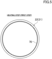
Fig. 5] Fig. 5 is a transverse sectional view of a body in a heating step. - [
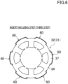
Fig. 6] Fig. 6 is a transverse sectional view of a stator core in an insert molding step. - [
Fig. 7] Fig. 7 is a transverse sectional view of the stator core in a joining step. - [
Fig. 8] Fig. 8 is a transverse sectional view of an electric motor according to a modification. - Embodiments of the present disclosure will now be described in detail with reference to the drawings. The present disclosure is not limited to the following embodiments, and various changes can be made thereto without departing from the technical idea of the present disclosure. The drawings are for conceptual illustration of the present disclosure. For ease of understanding, the sizes, ratios, or numbers of relevant elements are occasionally exaggerated or simplified as appropriate.
- A compressor (20) according to the present disclosure is to be provided in a refrigeration apparatus (1).
- The refrigeration apparatus (1) illustrated in
Fig. 1 includes the compressor (20) according to the present disclosure. The refrigeration apparatus (1) includes a refrigerant circuit (1a) that is filled with refrigerant. The refrigerant circuit (1a) includes the compressor (20), a radiator (2), a decompression mechanism (3), and an evaporator (4). The decompression mechanism (3) is an expansion valve. The refrigerant circuit (1a) is configured to perform a vapor-compression refrigeration cycle. - The refrigeration cycle progresses as follows. The refrigerant is compressed by the compressor (20) and radiates heat to air at the radiator (2). The refrigerant thus radiated heat is then decompressed by the decompression mechanism (3) and evaporates in the evaporator (4). The refrigerant thus evaporated is suctioned into the compressor (20) .
- The refrigeration apparatus (1) is an air conditioner. The air conditioner may be a cooling-only apparatus, a heating-only apparatus, or an air conditioner switchable between cooling and heating. Such an air conditioner includes a switching mechanism (for example, a four-way switching valve) configured to switch directions of refrigerant circulation. The refrigeration apparatus (1) may alternatively be a water heater, a chiller unit, a cooling apparatus configured to cool air in a closed space, or the like. The cooling apparatus is configured to cool air inside a refrigerator, a freezer, a container, or the like. The expansion mechanism includes an electronic expansion valve, a heat-sensitive expansion valve, an expander, or a capillary tube.
- As illustrated in
Fig. 2 , the compressor (20) is a rotary fluid machine. The compressor (20) includes a casing (21), an electric motor (30), a drive shaft (28), and a compression mechanism (50). The compressor (20), which is a rotary compressor, may alternatively be of any other type such as a scroll type. - The casing (21) houses the electric motor (30), the drive shaft (28), and the compression mechanism (50). The casing (21) is a hermetic container. The casing (21) is filled with the refrigerant discharged from the compression mechanism (50) and having a high pressure.
- The casing (21) is made of iron-based metal material. The casing (21) includes a body (22), a bottom part (23), and a top part (24). The body (22) is a metal cylindrical member. The body (22) has openings at two respective axial ends thereof. In the present example, the axial direction of the body (22) corresponds to the vertical direction. The bottom part (23) closes the lower one of the openings of the body (22). The top part (24) closes the upper one of the openings of the body (22).
- As illustrated in
Figs. 2 and3 , the electric motor (30) is located above the compression mechanism (50). The electric motor (30) includes a stator (31) and a rotor (40). The stator (31) is supported by the body (22) of the casing (21). How the stator (31) is fixed will be described in detail separately below. - The stator (31) includes a stator core (32) and coils (33) wound on the stator core (32). The stator core (32) includes electromagnetic steel plates that are stacked in the axial direction. As illustrated in
Fig. 3 , the stator core (32) includes an annular back yoke (34) and a plurality of (six in the present example) teeth (35) extending radially inward from the inner peripheral surface of the back yoke (34). - The back yoke (34) has in the outer peripheral surface thereof a plurality of (six in the present example) core cuts (36). The core cuts (36) are grooves each extending in the axial direction of the stator core (32). Projections (37) project radially outward between adjacent ones of the core cuts (36). The stator core (32) in the present example has six such projections (37). The projections (37) each have a pair of side faces (37a) each extending radially outward, and one end face (37b) extending between the one side face (37a). The projections (37) each extend from one axial end to the other axial end of the stator core (32).
- The rotor (40) is located on the inner side of the stator core (32). The drive shaft (28) is fixed at the center axis of the rotor (40). The rotor (40) has a plurality of (four in the present example) slots (41). Permanent magnets are embedded in the slots (41).
- The operating frequency of the electric motor (30) is controlled by an inverter device. In other words, the compressor (20) employs an inverter scheme in which the operating frequency is variable.
- The drive shaft (28) extends vertically along the center axis of the casing (21). The drive shaft (28) is to be rotated by the electric motor (30). The drive shaft (28) is rotatably supported by a bearing (29).
- The compression mechanism (50) includes a cylinder (51) and a piston (52) provided inside the cylinder (51). A cylinder chamber (53) is provided between the inner peripheral surface of the cylinder (51) and the outer peripheral surface of the piston (52). The piston (52) is to be driven by the drive shaft (28) in such a manner as to compress fluid in the cylinder chamber (53).
- The compressor (20) includes a suction pipe (45) and a discharge pipe (46). The suction pipe (45) extends into the body (22) in the radial direction and communicates with the cylinder chamber (53). The refrigerant, having a low pressure, in the refrigerant circuit (1a) is to be suctioned into the cylinder chamber (53) through the suction pipe (45). The discharge pipe (46) extends through the top part (24) in the axial direction and communicates with the space inside the casing (21). The refrigerant compressed by the compression mechanism (50) flows through the core cuts (36) of the electric motor (30) and so forth and is then delivered to the refrigerant circuit (1a) through the discharge pipe (46).
- A structure of fixing the stator (31) will now be described in detail. The compressor (20) according to the present embodiment includes a resin member (60) provided on the outer peripheral surface of the stator core (32), and an oxidized film (70) provided on the inner peripheral surface of the body (22) of the casing (21).
- As illustrated in
Figs. 2 to 4 , the compressor (20) includes a plurality of resin members (60). The compressor (20) in the present example includes six resin members (60). The resin members (60) are provided at the respective projections (37) of the stator core (32). Therefore, the number of the resin members (60) is equal to the number of the projections (37). For example, the stator core (32) may have eight projections (37) on the outer peripheral surface thereof. In such a case, the compressor (20) has eight resin members (60) provided one to one for the eight projections (37). - The resin member (60) is made of an insulating material. The resin member (60) has a function of suppressing the propagation of electromagnetic noise from the electric motor (30) to the outside of the casing (21). The resin member (60) in the present example is made of thermoplastic resin. The resin member (60) is made of PPS (polyphenylene sulfide), LCP (liquid-crystal polymer), PBT (polybutylene terephthalate), polyimide, PBI (polybenzimidazole), PEEK (polyether ether ketone), PSF (polysulfone), or PPO (polyphenylene oxide). The resin material (60) may alternatively be made of a composite obtained by adding glass fibers to any of the above thermoplastic resins.
- The resin member (60) is fixed to the outer peripheral surface of the stator core (32). The resin member (60) extends from one axial end to the other axial end of the stator core (32).
- The resin member (60) covers the entire surface of the corresponding projection (37) of the stator core (32). The resin member (60) is a single continuous member including a pair of base parts (61), a pair of sidewalls (62), and one fixed part (63).
- The pair of base parts (61) are located on portions of the outer peripheral surface of the back yoke (34) that are on two respective sides of the proximal part of the projection (37). The pair of base parts (61) each extend along the outer peripheral surface of the back yoke (34).
- The pair of sidewalls (62) cover the respective side faces (37a) of the projection (37). The pair of sidewalls (62) each extend in the direction in which the projection (37) projects.
- The fixed part (63) is continuous with each of the radially outer ends of the pair of sidewalls (62). The fixed part (63) in sectional view taken perpendicularly to the axial direction of the body (22) has an arc shape extending along the inner peripheral surface of the body (22). The fixed part (63) is located between the body (22) and the stator core (32). Exactly, the fixed part (63) is located between the oxidized film (70) and the stator core (32) .
- The resin member (60) is formed on the outer peripheral surface of the stator core (32) by insert molding, which will be described in detail separately below.
- As illustrated in
Fig. 4 , the oxidized film (70) is provided on the inner peripheral surface of the body (22) of the casing (21). Note that the oxidized film (70) illustrated inFig. 4 and other drawings has an exaggerated thickness. - The body (22) is made of an iron-based metal material. The oxidized film (70) is obtained by oxidizing the inner peripheral surface of the body (22). The oxidized film (70) in the present example is made of FeO (wustite), Fe2O3 (hematite), or Fe3O4 (magnetite). In particular, the oxidized film (70) may preferably be made of Fe3O4. Fe3O4 is dense and hard to deteriorate. The oxidized film (70) may contain iron hydroxide or iron oxyhydroxide.
- The oxidized film (70) is present at least at a position corresponding to the fixed part (63) of each resin member (60). The oxidized film (70) faces the resin member (60). The oxidized film (70) extends from one axial end to the other axial end of the stator core (32). The fixed part (63) is joined to the body (22) with the oxidized film (70) in between. The oxidized film (70) in the present example spreads over the entire circumference of the body (22). Therefore, the fixed part (63) and the oxidized film (70) are assuredly made to be in contact with each other. The oxidized film (70) provided on the body (22) may alternatively be present only at each of the positions corresponding to the fixed parts (63).
- The oxidized film (70) may preferably have a thickness of 2 pm or smaller. The oxidized film (70) may alternatively have a thickness smaller than 50 nm.
- A method for manufacturing the compressor (20) will now be described in detail with reference to
Figs. 5 to 7 . The method for manufacturing the compressor (20) includes a heating step, an insert molding step, and a joining step. The heating step corresponds to the first step according to the present disclosure. The insert molding step corresponds to the third step according to the present disclosure. The joining step corresponds to the second step according to the present disclosure. - The heating step, illustrated in
Fig. 5 , is performed on the cylindrical body (22) of the casing (21). The heating step is to form an oxidized film (70) on the inner peripheral surface of the body (22) of the casing (21) by heating the body (22). In the heating step, the body (22) may preferably be heated to 250°C or above. Thus, the oxidized film (70) is assuredly formed on the body (22). - The heating step of forming the oxidized film (70) on the inner peripheral surface of the body (22) may be performed in an atmosphere with an ambient pressure. Such a method facilitates the formation of the oxidized film (70) on the surface of the body (22). The heating step of forming the oxidized film (70) on the body (22) may be performed by induction heating (in the present example, high-frequency heating). Such a method quickly raises the temperature of the body (22) and thus facilitates the formation of the oxidized film (70) on the body (22). As in a modification illustrated in
Fig. 8 , the oxidized film (70) formed on the inner peripheral surface of the body (22) may be present only at each of the positions corresponding to the fixed parts (63). The oxidized film (70) in the modification illustrated inFig. 8 is absent at the positions corresponding to the core cuts (36). High-frequency heating is suitable for locally forming the oxidized film (70) on the inner peripheral surface of the body (22). - The body (22) heated in the heating step undergoes thermal expansion to have an increased diameter (inside diameter and outside diameter). Thus, the heating step increases the diameter of the body (20) in preparation for shrink fitting to be described in detail separately below, simultaneously with the formation of the oxidized film (70). Accordingly, the manufacturing time is reduced.
- The insert molding step, illustrated in
Fig. 6 , is to obtain a unit (U) by forming a resin member (60) on the outer peripheral surface of the stator core (32) through insert molding. Insert molding facilitates the formation of the resin member (60) on the outer peripheral surface of the stator core (32). The insert molding step may be performed before the heating step. Alternatively, the insert molding step may be performed between the heating step and the joining step. - The joining step, illustrated in
Fig. 7 , is performed by inserting the unit (U) into the body (22). The increase in the diameter of the body (22) in the heating step facilitates the insertion of the unit (U) into the body (22). In the joining step, the unit (U) is fitted into the body (22). In other words, the unit (U) is fixed inside the body (22) by shrink fitting. - When the oxidized film (70) of the body (22) comes into contact with the fixed part (63) of the resin member (60) in the joining step, the heat of the body (22) melts the resin member (60). The oxidized film (70) formed on the inner peripheral surface of the body (22) has a surface with microsized concavities and convexities. Therefore, the molten resin member (60) adheres to the oxidized film (70) in such a manner as to cover the concavities and convexities in the oxidized film (70). Consequently, the area of contact between the oxidized film (70) and the resin member (60) is increased. Furthermore, the resin member (60) flows into the concavities in the oxidized film (70), whereby a so-called anchoring effect is exerted that makes the resin member (60) difficult to come off the concavities.
- The joining step causes the temperature of the body (22) to decrease and thus reduces the diameter of the body (22). Consequently, the resin member (60) is tightly fastened between the body (22) and the stator core (32). Such a step facilitates the adhesion of the molten resin member (60) to the concavities and convexities in the oxidized film (70). When the temperature of the body (22) decreases, the molten resin member (60) on the surfaces of the concavities and convexities in the oxidized film (70) is solidified.
- The above steps increases the strength at the joint between the oxidized film (70) and the resin member (60) and thus prevents the peeling of the resin member (60) from the body (22). Consequently, the compressor (20) according to the present embodiment is assuredly provided with an effect of electromagnetic-noise reduction that is produced by the resin member (60).
- (5-1)
The compressor (20) includes the oxidized film (70) provided on the inner peripheral surface of the metal cylindrical body (22). The oxidized film (70) and the resin member (60) provided on the outer peripheral surface of the stator core (32) are joined to each other. - The oxidized film (70) has a surface with microsized concavities and convexities. Therefore, the area of contact between the oxidized film (70) and the resin member (60) is increased. Consequently, the strength at the joint between the body (22) and the resin member (60) is increased.
- (5-2)
The method for manufacturing the compressor (20) includes the heating step (first step) of forming the oxidized film (70) on the inner peripheral surface of the metal cylindrical body (22) by heating the body (22), and the joining step (second step) of fitting the stator core (32) to the outer peripheral surface of which the resin member (60) is fixed into the body (22) after the heating step and joining the resin member (60) in a molten state to the oxidized film (70). - In the heating step, while the oxidized film (70) is formed on the inner peripheral surface of the body (22) by heating the body (22), the diameter of the body (22) is increased. Hence, the work of forming the oxidized film (70) and the work of increasing the diameter of the body (22) are simultaneously achieved in a single step.
- In the joining step, the unit (U) is shrink-fitted into the body (22). Thus, the resin member (60) is firmly joined to the body (22) inside the body (22). Furthermore, since the molten resin member (60) is made to adhere to the concavities and convexities formed in the surface of the oxidized film (70), the area of contact between the resin member (60) and the oxidized film (70) is increased. Furthermore, since the molten resin member (60) is solidified in the concavities formed in the oxidized film (70), a so-called anchoring effect is exerted that makes the resin member (60) difficult to come off the oxidized film (70). The above functional effects increase the strength at the joint between the body (22) and the resin member (60).
- Furthermore, when the temperature of the body (22) decreases, the molten resin is solidified and the unit (U) is tightly fastened to the body (22). Thus, the strength at the joint between the oxidized film (70) and the resin member (60) is further increased.
- (5-3)
The method for manufacturing the compressor (20) includes the insert molding step (third step) of forming the resin member (60) on the outer peripheral surface of the stator core (32) by insert molding. The insert molding step facilitates the formation of the resin member (60) on the outer peripheral surface of the stator core (32) and increases the joining strength between the stator core (32) and the resin member (60). - (5-4)
In the heating step, the body (22) is heated to 250°C or above. Thus, the oxidized film (70) having concavities and convexities is formed on the inner peripheral surface of the body (22). - The above embodiment may be modified as follows.
- The heating step of forming the oxidized film (70) on the inner peripheral surface of the body (22) may be performed in an atmosphere with an oxygen partial pressure higher than in the ambient atmosphere. Specifically, the heating step of forming the oxidized film (70) on the inner peripheral surface of the body (22) may be performed by heating the body (22) in a furnace with a high oxygen partial pressure. Alternatively, the heating step of forming the oxidized film (70) on the inner peripheral surface of the body (22) may be performed by heating the body (22) while blowing oxygen gas to the body (22). As another alternative, the heating step of forming the oxidized film (70) on the inner peripheral surface of the body (22) may be performed by infrared heating.
- Forming the oxidized film (70) in an atmosphere with an oxygen partial pressure higher than in the ambient atmosphere increases the thickness of the oxidized film (70) .
- The heating step of forming the oxidized film (70) on the inner peripheral surface of the body (22) may alternatively be performed in an atmosphere with an oxygen partial pressure lower than in the ambient atmosphere. Thus, the thickness of the oxidized film (70) is reduced to, for example, smaller than 50 nm.
- It would be understood that details of the embodiments and modifications described above are changeable in various ways without departing from the essence and scope of the appended claims. The features of the above embodiments, modifications, and other possible embodiments may be combined or exchanged as appropriate, unless the functions within the scope of the present disclosure are deteriorated.
- The terms "first", "second", "third", and so on used in the above description are only for distinguishing relevant elements denoted by such terms and do not limit the numbers or order of such elements.
- As described above, the present disclosure is useful for compressors.
-
- 1
- refrigeration apparatus
- 20
- compressor
- 22
- body
- 32
- stator core
- 60
- resin member
- 70
- oxidized film
Claims (10)
- A compressor comprising:a metal cylindrical body (22);a stator core (32); anda resin member (60) fixed to an outer peripheral surface of the stator core (32),wherein an oxidized film (70) is provided on an inner peripheral surface of the body (22), andwherein the oxidized film (70) and the resin member (60) are joined to each other.
- The compressor according to Claim 1 or 2,
wherein the oxidized film (70) contains at least one of iron oxide, iron hydroxide, and iron oxyoxide. - A refrigeration apparatus comprising the compressor (20) according to Claim 1 or 2.
- A method for manufacturing a compressor, comprising:a first step of forming an oxidized film (70) on an inner peripheral surface of a metal cylindrical body (22) by heating the body (22); anda second step of fitting a stator core (32) to an outer peripheral surface of which a resin member (60) is fixed into the body (22) after the first step and joining the resin member (60) in a molten state to the oxidized film (70).
- The method for manufacturing a compressor according to Claim 4, further comprising: a third step of forming the resin member (60) on the outer peripheral surface of the stator core (32) by insert molding.
- The method for manufacturing a compressor according to Claim 5,
wherein the body (22) is heated to 250°C or above in the first step. - The method for manufacturing a compressor according to any one of Claims 4 to 6, wherein the first step of forming the oxidized film (70) on the inner peripheral surface of the body (22) is performed in an ambient atmosphere.
- The method for manufacturing a compressor according to any one of Claims 4 to 6,
wherein the first step of forming the oxidized film (70) on the inner peripheral surface of the body (22) is performed in an atmosphere with an oxygen partial pressure higher than in an ambient atmosphere. - The method for manufacturing a compressor according to any one of Claims 4 to 6,
wherein the first step of forming the oxidized film (70) on the inner peripheral surface of the body (22) is performed in an atmosphere with an oxygen partial pressure lower than in an ambient atmosphere. - The method for manufacturing a compressor according to any one of Claims 4 to 9,
wherein the first step of forming the oxidized film (70) on the inner peripheral surface of the body (22) is performed by infrared heating, heating in a furnace, or induction heating.
Applications Claiming Priority (2)
| Application Number | Priority Date | Filing Date | Title |
|---|---|---|---|
| JP2021178547A JP2023067377A (en) | 2021-11-01 | 2021-11-01 | Compressor, Refrigeration Equipment, and Compressor Manufacturing Method |
| PCT/JP2022/037623 WO2023074320A1 (en) | 2021-11-01 | 2022-10-07 | Compressor, refrigeration device, and method for manufacturing compressor |
Publications (2)
| Publication Number | Publication Date |
|---|---|
| EP4401287A1 true EP4401287A1 (en) | 2024-07-17 |
| EP4401287A4 EP4401287A4 (en) | 2025-03-26 |
Family
ID=86159836
Family Applications (1)
| Application Number | Title | Priority Date | Filing Date |
|---|---|---|---|
| EP22886650.5A Pending EP4401287A4 (en) | 2021-11-01 | 2022-10-07 | COMPRESSOR, COOLING DEVICE AND METHOD FOR MANUFACTURING A COMPRESSOR |
Country Status (4)
| Country | Link |
|---|---|
| EP (1) | EP4401287A4 (en) |
| JP (1) | JP2023067377A (en) |
| CN (1) | CN118176645A (en) |
| WO (1) | WO2023074320A1 (en) |
Family Cites Families (7)
| Publication number | Priority date | Publication date | Assignee | Title |
|---|---|---|---|---|
| JP4592143B2 (en) * | 2000-04-06 | 2010-12-01 | パナソニック株式会社 | Compressor and electric motor |
| JP2005057859A (en) * | 2003-08-01 | 2005-03-03 | Matsushita Electric Ind Co Ltd | Small diameter motor |
| JP4555160B2 (en) * | 2005-06-01 | 2010-09-29 | 株式会社神戸製鋼所 | Steel plate for dissimilar welding with aluminum material and dissimilar material joint |
| JP2007113728A (en) * | 2005-10-21 | 2007-05-10 | Matsushita Electric Ind Co Ltd | Hydrodynamic bearing device and manufacturing method thereof |
| JP6263874B2 (en) * | 2013-06-28 | 2018-01-24 | 愛知製鋼株式会社 | Carburizing method for high Si carburizing steel |
| WO2015063871A1 (en) * | 2013-10-29 | 2015-05-07 | 三菱電機株式会社 | Permanent magnet embedded electric motor, compressor, and refrigerating and air-conditioning device |
| WO2017065256A1 (en) * | 2015-10-14 | 2017-04-20 | 株式会社豊田中央研究所 | Metal-plastic joining member and method for manufacturing same |
-
2021
- 2021-11-01 JP JP2021178547A patent/JP2023067377A/en active Pending
-
2022
- 2022-10-07 CN CN202280071876.8A patent/CN118176645A/en active Pending
- 2022-10-07 EP EP22886650.5A patent/EP4401287A4/en active Pending
- 2022-10-07 WO PCT/JP2022/037623 patent/WO2023074320A1/en not_active Ceased
Also Published As
| Publication number | Publication date |
|---|---|
| JP2023067377A (en) | 2023-05-16 |
| CN118176645A (en) | 2024-06-11 |
| EP4401287A4 (en) | 2025-03-26 |
| WO2023074320A1 (en) | 2023-05-04 |
Similar Documents
| Publication | Publication Date | Title |
|---|---|---|
| CN102638118B (en) | Rotor, sealed compressor, and refrigerating cycle device | |
| JP6636144B2 (en) | Stator, electric motor, compressor, and refrigeration air conditioner | |
| US10916989B2 (en) | Motor, compressor, refrigerating and air conditioning apparatus, and method for manufacturing motor | |
| CN101776056A (en) | Hermetic compressor and refrigerating cycle apparatus | |
| JP2013042588A (en) | Electric motor | |
| CN111164859B (en) | Stator, motor, compressor, air conditioner, and manufacturing method of stator | |
| US20120301334A1 (en) | Compressor and Refrigerating Cycle Apparatus | |
| CN110431726A (en) | Rotors, motors, compressors, blowers and air conditioners | |
| CN113812069A (en) | Motor, compressor, air conditioner, and method for manufacturing motor | |
| WO2020170390A1 (en) | Motor, compressor, and air conditioning device | |
| JP2010279126A (en) | Electric motor stator core, electric motor, hermetic compressor, refrigeration cycle equipment | |
| CN117098915A (en) | Rotating machinery units, compressors and refrigeration units | |
| RU2150609C1 (en) | Centrifugal compressor unit and electric motor | |
| EP4478585B1 (en) | Rotating electrical machine, manufacturing method therefor, compressor, blower, and refrigeration device equipped with rotating electrical machine | |
| WO2020170418A1 (en) | Motor, compressor, and air conditioning device | |
| CN206302218U (en) | Stator cores, compressors and refrigeration cycle devices | |
| JPWO2020053927A1 (en) | Rotors, electric motors, compressors, and refrigeration and air conditioners | |
| WO2023074320A1 (en) | Compressor, refrigeration device, and method for manufacturing compressor | |
| JP4156506B2 (en) | Electric motor, hermetic compressor, refrigeration air conditioner and wedge | |
| EP4361439A1 (en) | Method for manufacturing compressor | |
| JP7258140B2 (en) | Rotors, electric motors, compressors, and air conditioners | |
| JP5135779B2 (en) | Compressor | |
| JP2008202455A (en) | Compressor | |
| JP3601288B2 (en) | Magnetization method for permanent magnet type motor | |
| JP2008138591A5 (en) |
Legal Events
| Date | Code | Title | Description |
|---|---|---|---|
| STAA | Information on the status of an ep patent application or granted ep patent |
Free format text: STATUS: THE INTERNATIONAL PUBLICATION HAS BEEN MADE |
|
| PUAI | Public reference made under article 153(3) epc to a published international application that has entered the european phase |
Free format text: ORIGINAL CODE: 0009012 |
|
| STAA | Information on the status of an ep patent application or granted ep patent |
Free format text: STATUS: REQUEST FOR EXAMINATION WAS MADE |
|
| 17P | Request for examination filed |
Effective date: 20240409 |
|
| AK | Designated contracting states |
Kind code of ref document: A1 Designated state(s): AL AT BE BG CH CY CZ DE DK EE ES FI FR GB GR HR HU IE IS IT LI LT LU LV MC ME MK MT NL NO PL PT RO RS SE SI SK SM TR |
|
| DAV | Request for validation of the european patent (deleted) | ||
| DAX | Request for extension of the european patent (deleted) | ||
| P01 | Opt-out of the competence of the unified patent court (upc) registered |
Free format text: CASE NUMBER: APP_1108/2025 Effective date: 20250108 |
|
| REG | Reference to a national code |
Ref country code: DE Ref legal event code: R079 Free format text: PREVIOUS MAIN CLASS: H02K0005040000 Ipc: F04B0039000000 |
|
| A4 | Supplementary search report drawn up and despatched |
Effective date: 20250221 |
|
| RIC1 | Information provided on ipc code assigned before grant |
Ipc: H02K 15/02 20060101ALI20250217BHEP Ipc: H02K 5/04 20060101ALI20250217BHEP Ipc: H02K 1/18 20060101ALI20250217BHEP Ipc: H02K 1/04 20060101ALI20250217BHEP Ipc: F04C 29/00 20060101ALI20250217BHEP Ipc: F04C 23/00 20060101ALI20250217BHEP Ipc: F04C 18/356 20060101ALI20250217BHEP Ipc: F04C 18/02 20060101ALI20250217BHEP Ipc: F04B 39/12 20060101ALI20250217BHEP Ipc: F04B 39/02 20060101ALI20250217BHEP Ipc: F04B 39/00 20060101AFI20250217BHEP |
|
| GRAP | Despatch of communication of intention to grant a patent |
Free format text: ORIGINAL CODE: EPIDOSNIGR1 |
|
| STAA | Information on the status of an ep patent application or granted ep patent |
Free format text: STATUS: GRANT OF PATENT IS INTENDED |