EP4401088A2 - Sehr vereinfachte siedewasserreaktoren zur kommerziellen stromerzeugung - Google Patents
Sehr vereinfachte siedewasserreaktoren zur kommerziellen stromerzeugung Download PDFInfo
- Publication number
- EP4401088A2 EP4401088A2 EP24179997.2A EP24179997A EP4401088A2 EP 4401088 A2 EP4401088 A2 EP 4401088A2 EP 24179997 A EP24179997 A EP 24179997A EP 4401088 A2 EP4401088 A2 EP 4401088A2
- Authority
- EP
- European Patent Office
- Prior art keywords
- reactor
- containment
- emergency
- plant
- containment structure
- Prior art date
- Legal status (The legal status is an assumption and is not a legal conclusion. Google has not performed a legal analysis and makes no representation as to the accuracy of the status listed.)
- Pending
Links
- XLYOFNOQVPJJNP-UHFFFAOYSA-N water Substances O XLYOFNOQVPJJNP-UHFFFAOYSA-N 0.000 title claims abstract description 11
- 238000009835 boiling Methods 0.000 title claims abstract description 9
- 230000005611 electricity Effects 0.000 title description 6
- 239000002826 coolant Substances 0.000 claims abstract description 72
- 238000002955 isolation Methods 0.000 claims abstract description 53
- 238000001816 cooling Methods 0.000 claims abstract description 17
- 230000035515 penetration Effects 0.000 claims description 18
- 238000000034 method Methods 0.000 claims description 12
- 229910000831 Steel Inorganic materials 0.000 claims description 3
- 239000010959 steel Substances 0.000 claims description 3
- 238000007789 sealing Methods 0.000 claims description 2
- 238000000605 extraction Methods 0.000 claims 4
- 239000012530 fluid Substances 0.000 abstract description 13
- 230000001629 suppression Effects 0.000 description 10
- 238000013461 design Methods 0.000 description 6
- 238000010276 construction Methods 0.000 description 5
- 239000000463 material Substances 0.000 description 5
- 238000010248 power generation Methods 0.000 description 5
- 230000035939 shock Effects 0.000 description 5
- 239000000446 fuel Substances 0.000 description 4
- 238000013021 overheating Methods 0.000 description 4
- 230000001052 transient effect Effects 0.000 description 4
- 230000002159 abnormal effect Effects 0.000 description 2
- 238000001514 detection method Methods 0.000 description 2
- 230000000694 effects Effects 0.000 description 2
- 230000007774 longterm Effects 0.000 description 2
- 238000012423 maintenance Methods 0.000 description 2
- 238000012546 transfer Methods 0.000 description 2
- 238000003466 welding Methods 0.000 description 2
- 238000009833 condensation Methods 0.000 description 1
- 230000005494 condensation Effects 0.000 description 1
- 230000003247 decreasing effect Effects 0.000 description 1
- 238000004880 explosion Methods 0.000 description 1
- 239000002360 explosive Substances 0.000 description 1
- 230000004992 fission Effects 0.000 description 1
- 230000005484 gravity Effects 0.000 description 1
- 239000013529 heat transfer fluid Substances 0.000 description 1
- 238000005304 joining Methods 0.000 description 1
- 238000004519 manufacturing process Methods 0.000 description 1
- 239000002184 metal Substances 0.000 description 1
- 238000013508 migration Methods 0.000 description 1
- 230000005012 migration Effects 0.000 description 1
- 238000012354 overpressurization Methods 0.000 description 1
- 230000002265 prevention Effects 0.000 description 1
- 230000005855 radiation Effects 0.000 description 1
- 230000002285 radioactive effect Effects 0.000 description 1
- 239000012857 radioactive material Substances 0.000 description 1
- 230000003014 reinforcing effect Effects 0.000 description 1
- 230000002441 reversible effect Effects 0.000 description 1
Images


Classifications
-
- G—PHYSICS
- G21—NUCLEAR PHYSICS; NUCLEAR ENGINEERING
- G21C—NUCLEAR REACTORS
- G21C9/00—Emergency protection arrangements structurally associated with the reactor, e.g. safety valves provided with pressure equalisation devices
- G21C9/004—Pressure suppression
-
- F—MECHANICAL ENGINEERING; LIGHTING; HEATING; WEAPONS; BLASTING
- F16—ENGINEERING ELEMENTS AND UNITS; GENERAL MEASURES FOR PRODUCING AND MAINTAINING EFFECTIVE FUNCTIONING OF MACHINES OR INSTALLATIONS; THERMAL INSULATION IN GENERAL
- F16K—VALVES; TAPS; COCKS; ACTUATING-FLOATS; DEVICES FOR VENTING OR AERATING
- F16K3/00—Gate valves or sliding valves, i.e. cut-off apparatus with closing members having a sliding movement along the seat for opening and closing
- F16K3/02—Gate valves or sliding valves, i.e. cut-off apparatus with closing members having a sliding movement along the seat for opening and closing with flat sealing faces; Packings therefor
- F16K3/0254—Gate valves or sliding valves, i.e. cut-off apparatus with closing members having a sliding movement along the seat for opening and closing with flat sealing faces; Packings therefor being operated by particular means
-
- F—MECHANICAL ENGINEERING; LIGHTING; HEATING; WEAPONS; BLASTING
- F16—ENGINEERING ELEMENTS AND UNITS; GENERAL MEASURES FOR PRODUCING AND MAINTAINING EFFECTIVE FUNCTIONING OF MACHINES OR INSTALLATIONS; THERMAL INSULATION IN GENERAL
- F16K—VALVES; TAPS; COCKS; ACTUATING-FLOATS; DEVICES FOR VENTING OR AERATING
- F16K3/00—Gate valves or sliding valves, i.e. cut-off apparatus with closing members having a sliding movement along the seat for opening and closing
- F16K3/30—Details
- F16K3/314—Forms or constructions of slides; Attachment of the slide to the spindle
-
- G—PHYSICS
- G21—NUCLEAR PHYSICS; NUCLEAR ENGINEERING
- G21C—NUCLEAR REACTORS
- G21C1/00—Reactor types
- G21C1/02—Fast fission reactors, i.e. reactors not using a moderator ; Metal cooled reactors; Fast breeders
- G21C1/028—Fast fission reactors, i.e. reactors not using a moderator ; Metal cooled reactors; Fast breeders cooled by a pressurised coolant
-
- G—PHYSICS
- G21—NUCLEAR PHYSICS; NUCLEAR ENGINEERING
- G21C—NUCLEAR REACTORS
- G21C1/00—Reactor types
- G21C1/04—Thermal reactors ; Epithermal reactors
- G21C1/06—Heterogeneous reactors, i.e. in which fuel and moderator are separated
- G21C1/08—Heterogeneous reactors, i.e. in which fuel and moderator are separated moderator being highly pressurised, e.g. boiling water reactor, integral super-heat reactor, pressurised water reactor
- G21C1/086—Pressurised water reactors
-
- G—PHYSICS
- G21—NUCLEAR PHYSICS; NUCLEAR ENGINEERING
- G21C—NUCLEAR REACTORS
- G21C13/00—Pressure vessels; Containment vessels; Containment in general
- G21C13/02—Details
-
- G—PHYSICS
- G21—NUCLEAR PHYSICS; NUCLEAR ENGINEERING
- G21C—NUCLEAR REACTORS
- G21C13/00—Pressure vessels; Containment vessels; Containment in general
- G21C13/02—Details
- G21C13/028—Seals, e.g. for pressure vessels or containment vessels
-
- G—PHYSICS
- G21—NUCLEAR PHYSICS; NUCLEAR ENGINEERING
- G21C—NUCLEAR REACTORS
- G21C15/00—Cooling arrangements within the pressure vessel containing the core; Selection of specific coolants
- G21C15/18—Emergency cooling arrangements; Removing shut-down heat
-
- G—PHYSICS
- G21—NUCLEAR PHYSICS; NUCLEAR ENGINEERING
- G21C—NUCLEAR REACTORS
- G21C9/00—Emergency protection arrangements structurally associated with the reactor, e.g. safety valves provided with pressure equalisation devices
- G21C9/016—Core catchers
-
- G—PHYSICS
- G21—NUCLEAR PHYSICS; NUCLEAR ENGINEERING
- G21C—NUCLEAR REACTORS
- G21C13/00—Pressure vessels; Containment vessels; Containment in general
- G21C13/08—Vessels characterised by the material; Selection of materials for pressure vessels
- G21C13/087—Metallic vessels
-
- G—PHYSICS
- G21—NUCLEAR PHYSICS; NUCLEAR ENGINEERING
- G21C—NUCLEAR REACTORS
- G21C13/00—Pressure vessels; Containment vessels; Containment in general
- G21C13/08—Vessels characterised by the material; Selection of materials for pressure vessels
- G21C13/093—Concrete vessels
-
- G—PHYSICS
- G21—NUCLEAR PHYSICS; NUCLEAR ENGINEERING
- G21C—NUCLEAR REACTORS
- G21C17/00—Monitoring; Testing ; Maintaining
- G21C17/02—Devices or arrangements for monitoring coolant or moderator
- G21C17/04—Detecting burst slugs
- G21C17/042—Devices for selective sampling, e.g. valves, shutters, rotatable selector valves
-
- G—PHYSICS
- G21—NUCLEAR PHYSICS; NUCLEAR ENGINEERING
- G21C—NUCLEAR REACTORS
- G21C9/00—Emergency protection arrangements structurally associated with the reactor, e.g. safety valves provided with pressure equalisation devices
- G21C9/02—Means for effecting very rapid reduction of the reactivity factor under fault conditions, e.g. reactor fuse; Control elements having arrangements activated in an emergency
- G21C9/033—Means for effecting very rapid reduction of the reactivity factor under fault conditions, e.g. reactor fuse; Control elements having arrangements activated in an emergency by an absorbent fluid
-
- Y—GENERAL TAGGING OF NEW TECHNOLOGICAL DEVELOPMENTS; GENERAL TAGGING OF CROSS-SECTIONAL TECHNOLOGIES SPANNING OVER SEVERAL SECTIONS OF THE IPC; TECHNICAL SUBJECTS COVERED BY FORMER USPC CROSS-REFERENCE ART COLLECTIONS [XRACs] AND DIGESTS
- Y02—TECHNOLOGIES OR APPLICATIONS FOR MITIGATION OR ADAPTATION AGAINST CLIMATE CHANGE
- Y02E—REDUCTION OF GREENHOUSE GAS [GHG] EMISSIONS, RELATED TO ENERGY GENERATION, TRANSMISSION OR DISTRIBUTION
- Y02E30/00—Energy generation of nuclear origin
- Y02E30/30—Nuclear fission reactors
Definitions
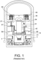
- FIG. 1 is a schematic of a containment building 36 that houses a reactor pressure vessel 42 with various configurations of fuel 41 and reactor internals for producing nuclear power in a related art economic simplified boiling water reactor (ESBWR).
- Reactor 42 is conventionally capable of producing and approved to produce several thousand megawatts of thermal energy through nuclear fission.
- Reactor 42 sits in a drywell 51, including upper drywell 54 and a lower drywell 3 that provides space surrounding and under reactor 42 for external components and personnel.
- Reactor 42 is typically several dozen meters high, and containment building 36 even higher above ground elevation, to facilitate natural circulation cooling and construction from ground level.
- a sacrificial melt layer 1 called a basemat-internal melt arrest and coolability device, is positioned directly below reactor 1 to cool potential falling debris, melted reactor structures, and/or coolant and prevent their progression into a ground below containment 36.
- containment 36 may include a pressure suppression chamber 58 surrounding reactor 42 in an annular or other fashion and holding suppression pool 59.
- Suppression pool 59 may include an emergency steam vent used to divert steam from a main steam line into suppression pool 59 for condensation and heat sinking, to prevent overheating and over-pressurization of containment 36.
- Suppression pool 59 may also include flow paths that allow fluid flowing into drywell 54 to drain, or be pumped, into suppression pool 59.
- Suppression pool 59 may further include other heat-exchangers or drains configured to remove heat or pressure from containment 36 following a loss of coolant accident.
- An emergency core cooling system line and pump 10 may inject coolant from suppression pool 59 into reactor 42 in order to make up lost feedwater and/or other emergency coolant supply.
- a gravity-driven cooling system (GDCS) pool 37 can further provide coolant to reactor 42 via piping 57.
- a passive containment cooling system (PCCS) pool 65 may condense any steam inside containment 36, such as steam created through reactor depressurization to lower containment pressure or a main steam line break, and feed the condensed fluid back into GDCS pool 37.
- An isolation cooling system (ICS) pool 66 may take steam directly at pressure from reactor 42 and condense the same for recirculation back into rector 42.
- ESBWR ESBWR Plant General Description
- Example embodiments include nuclear reactors having virtually no failure mode outside of their containment.
- Example embodiment nuclear reactors may be similar to ESBWR designs with larger height-to-width ratios that enable natural circulation within the pressure vessel, but smaller, especially in the width direction, to produce less than 1000 megawatts thermal energy.
- Example embodiment containments may fully surround the nuclear reactor and prevent fluid leakage out of the containment even at elevated pressures.
- Example embodiment containments may be extremely simplified with no coolant sources like GDCS pools, suppression pools, or moving coolant pumps.
- One of more coolant sources outside containment, like isolation condenser systems, are sufficient to provide long-term, reliable cooling to the nuclear reactor.
- Example embodiment isolation valves can be used at each fluid connection to the reactor to make the reactor integrally isolatable, including for the primary coolant loop and the emergency coolant source.
- Example-embodiment isolation valves are redundant and integral with the nuclear reactor and fluid conduit and fabricated up to ASME nuclear standards for reactor vessels so as to eliminate risk of shear failure. Where example embodiment containment is penetrated, penetration seals may surround and make impermeable containment at the penetrations to high gauge pressures.
- Example embodiment containments and reactors may be completely underground and, along with an emergency coolant source, surrounded by a seismic silo that shields the same from earthquake and other shocks. Limited access pointed, such as a single top shield covering the silo and containment, may provide simplified access for maintenance, flooding, and/or refueling.
- ESBWRs have large 1000+ megawatt-electric power ratings with associated large reactor volumes and construction costs.
- the inventors have further recognized that the large sizes of ESBWRs generally require large containments that can feasibly be constructed only above ground.
- ESBWRs also use numerous passive safety systems with piping conduits and other flowpaths to the reactor capable of breaking or leaking, causing a loss of coolant accident.
- the inventors have further recognized that ESBWRs are useable primarily for long-term, baseline power generation, without modularity or flexibility of construction and operation in areas needing immediate or peaking power generation capacity. To overcome these newly-recognized problems as well as others, the inventors have developed example embodiments and methods described below to address these and other problems recognized by the inventors with unique solutions enabled by example embodiments.
- the present invention is nuclear reactors, plants containing the same, and methods of operating such reactors and plants.
- the few example embodiments and example methods discussed below illustrate just a subset of the variety of different configurations that can be used as and/or in connection with the present invention.
- FIG. 2 is a schematic of an example embodiment reactor system 100 including example embodiment reactor 142, example embodiment containment 136, and related cooling and power generation systems.
- example embodiment system 100 is useable with conventional and known power generating equipment such as high- and low-pressure turbines, electrical generators, switchyards, condensers, cooling towers or heat sinks, etc., which may connect, for example to main feedwater line 120 and main steam line 125 in a similar fashion to any power generation facility.
- Example embodiment containment 136 is composed of resilient, impermeable material for limiting migration of radioactive material and plant components in the case of a transient or accident scenario.
- containment 136 may be an integrally-formed concrete structure, potentially with reinforcing internal steel or rebar skeleton, several inches or feet thick. Or, for example, as discussed below, because containment 136 may be relatively smaller, an all-steel body may be use without being prohibitively expensive or complexly-fabricated, to enhance strength, radiation shielding, and lifespan of containment 136.
- example embodiment containment 136 may be underground, potentially housed in a reactor silo 190.
- a concrete lid 191 or other surface shield level with, or below, ground 90 may enclose silo 190 housing example embodiment reactor 142 and containment 136.
- Silo 190 and lid 191 may be seismically isolated or hardened so as to minimize any shock wave encountered from the ground and thus minimize impact of seismic events on reactor 142.
- example embodiment system 100 may present an exceedingly small strike target and/or be hardened against surface impacts and explosions. Further, if underground, example embodiment system 100 may have additional containment against radioactive release and enable easier flooding in the case of emergency cooling.
- any electricity-generating equipment may be connected above ground without loss of these benefits, and/or such equipment may also be place below ground.
- example embodiment containment 136 may be compact and simplified relative to existing nuclear power plants, including the ESBWR.
- Conventional operating and emergency equipment including a GDCS, PCCS, suppression pools, Bimacs, backup batteries, wetwells, torii, etc. may be wholly omitted from containment 136.
- Containment 136 may be accessible through fewer access points as well, such as a single top access point under shield 191 that permits access to reactor 142 for refueling and maintenance.
- example embodiment reactor 142 and core 141 may not require a bimac for floor arrest and cooling, because no realistic scenario exists for fuel relocation into containment 136; nonetheless, example embodiment containment 136 may have sufficient floor thickness and spread area to accommodate and cool any relocated core in its entirety, as shown in FIG. 2 . Moreover, total penetrations through containment 136 may be minimized and or isolated, as discussed further in connection with FIG. 3 , below, to reduce or effectively eliminate risk of leakage from containment 136.
- Example embodiment reactor 142 may be a boiling-water type reactor, similar to approved ESBWR designs in reactor internals and height. Reactor 142 may be smaller than, such as one-fifth the volume of, ESBWRs, producing only up to 600 megawatts of electricity for example, with a proportionally smaller core 141, for example operating at less than 1000 megawatt-electric. For example, example embodiment reactor 142 may be almost 28 meters in height and slightly over 3 meters in diameter, with internals matching ESBWR internals but scaled down proportionally in the transverse direction to operate at approximately 900 megawatt-thermal and 300 megawatt-electric ratings.
- reactor 142 may be a same proportion as an ESBWR, with an approximate 3.9 height-to-width ratio, scaled down to a smaller volume.
- other dimensions are useable with example embodiment reactor 142, with smaller height-to-width ratios such as 2.7, or 2.0, that may enable natural circulation at smaller sizes or proper flow path configuration inside the reactor.
- example embodiment reactor 142 may preserve natural circulation effects achieved by known ESBWRs in example embodiment reactor 142.
- smaller reactor 142 may more easily be positioned underground with associated cooling equipment and/or possess less overheating and damage risk due to smaller fuel inventory in core 141.
- smaller example embodiment reactor 142 with lower power rating may more readily satisfy modular power or peaking power demands, with easier startup, shutdown, and/or reduced power operations to better match energy demand.
- a coolant loop such as main feedwater line 120 and main steam line 125, may flow into reactor 142 in order to provide moderator, coolant, and/or heat transfer fluid for electricity generation.
- An emergency coolant source such as one or more isolation condenser systems 166, may further provide emergency cooling to reactor 142 in the instance of loss of feedwater from line 120.
- Each isolation condenser system 166 may further have two connections to example embodiment reactor 142, one for steam outlet and one for condensate return to reactor 142.
- Each of these connections to reactor 142 may use isolation valves 111, 112, 167, and/or 168 that are integrally connected to reactor 142 inside containment 136 and represent negligible failure risk.
- FIG. 3 is a schematic of an example embodiment isolation valve 200, which may be used for any of valves 111, 112, 167, and/or 168, or any other valve for fluid delivery to / removal from example embodiment reactor 142 through example embodiment containment 136.
- valves 111, 112, 167, and 168 are shown straddling containment 136 in FIG. 2 , it is understood that they may also be completely inside containment 136 as shown in FIG. 3 .
- Example embodiment valve body 201 including two isolation gate valves 210 and 220 and connections between the two, has high-reliability operation without any comparable risk of leakage or failure.
- valve 200 is not susceptible to guillotine-type shear breaks found in conventional steam and feedwater lines inside containment of ESBWRs. If used with a smaller-size example embodiment reactor 142, valve 200 may be smaller and/or simplified and control relatively less feedwater or steam flows than conventional conduits and valves, further reducing fabrication challenges and risk of failure in example embodiment system 100 ( FIG. 2 ).
- valve 200 includes a primary isolation gate valve 210 and a secondary isolation gate valve 220 for redundant sealing and/or blowout prevention.
- Primary and secondary gate valves 210 and 220 are integrally formed with valve body 201 that connects to reactor 142 and a flow conduit, permitting flow therebetween with no risk of breakage or disconnect.
- Higher-reliability actuators 211 and 212 may each be respectively connected to primary and secondary gate valves 210 and 220 and allow minimal leakage from gate valves 210 and 220.
- Primary isolation gate valve 210 and actuator 211 may be a CCI high-energy isolation gate valve and actuator disclosed in "CCI Nuclear Valve Resource Guide for Power Uprate and Productivity Gains," 2003, CCI, incorporated herein by reference in its entirety, for example.
- Secondary isolation gate valve 220 and actuator 212 may be another CCI high-energy isolation gate valve and actuator.
- valves 210 and 220 may be check valves, globe valves, etc. having high reliability and no significant shear breakage failure mode when formed together in valve body 201.
- Valve body 201 may be made of a single piece of forged material, such as a metal useable in an operating nuclear reactor environment, including all of primary isolation gate valve 210 and secondary isolation gate valve 220 as a single piece.
- ASME-standard welding such as between primary and secondary valves 210 and 220, may be used at reactor vessel-level of reliability.
- Valve body 201 is further integrally welded to reactor 142 using ASME-standard welding with negligible failure possibility.
- reactor 142 all flow paths or conduits may be integral with reactor 142 inside containment 136, where "integral" is defined throughout this disclosure as "with material continuity and inseparability, including single-piece forged and welded materials at ASME nuclear specifications.” Because example embodiment valve 200 as integrally joined to reactor 142 and cannot realistically break, possibility of an un-isolatable loss of coolant accident from reactor 142 is effectively eliminated. In this way, reactor 142 is integrally isolatable from any external conduit (such as feedwater line 120 or main steam line 125 in FIG. 2 ) to which valve body may join in any manner.
- any external conduit such as feedwater line 120 or main steam line 125 in FIG. 2
- a penetration seal 102 may be used to isolate and impermeably seal about valve body 201.
- Penetration seal 102 may maintain a large pressure gradient across containment 136 without passage of material about valve 200.
- containment seal 102 at an end valve body 201 effectively eliminates the risk of any pipe break injecting coolant into containment 140 from the balance of plant piping inventory.
- penetration seal 102 may be positioned on a conduit joining to valve body 201, at a very short distance inside containment 136.
- valves 111, 112, 167, 168 and any other fluid connections to reactor 142 may use example embodiment valve 200 of FIG. 3 to eliminate any non-negligible risk of flow path failure inside containment 136.
- Valves 112, 111, 168, and/or 167 may be passively actuated into fail-safe configurations.
- main feedwater valve 111 and/or main steam valve 112 may be sealed closed in the event of an accident or abnormal operating condition.
- Battery-operated, explosive, and/or fail-closed solenoid actuators of the valves for example, may be initiated upon detecting abnormal operating conditions.
- isolation condenser valves 167 and 168 may be opened with similar reliability, allowing passive heat removal from reactor 142 through isolation condenser system 166.
- Isolation condensers 166 may be known designs that transfer reactor heat to ambient environment and condense reactor coolant without leakage. Similarly, isolation condensers 166 may be condensers 300 from co-owned application 15/635,400 to Hunt, Dahlgren, and Marquino, filed under attorney docket 5.0055.1 for ISOLATION CONDENSER SYSTEMS FOR VERY SIMPLIFIED BOILING WATER REACTORS and incorporated by reference herein in its entirety.
- the relatively lower power of example embodiment reactor 142 may permit safe cooling through simple, passive operation of isolation condenser 166 for several days without operator intervention without risk of overheating, loss of coolant, or other damage to reactor 142.
- example embodiment containment 136 may be sealed about any other valve or penetration, such as power systems, instrumentation, coolant cleanup lines, etc.
- the fewer penetrations, smaller size, lack of systems inside, and/or underground placement of containment 136 may permit a higher operating pressure, potentially up to near reactor pressures of several hundred, such as 300, psig without any leakage potential.
- example embodiment reactor system 100 several different features permit significantly decreased loss of coolant probability, enable responsive and flexible power generation, reduce plant footprint and above-ground strike target, and/or simplify nuclear plant construction and operation.
- example embodiment reactor 142 may still benefit from passive safety features such as natural circulation inherent in the ESBWR design, while allowing a significantly smaller and simplified example embodiment containment 136 and reliance on passive isolation condensers 166 for emergency heat removal.
Landscapes
- Engineering & Computer Science (AREA)
- Physics & Mathematics (AREA)
- General Engineering & Computer Science (AREA)
- Plasma & Fusion (AREA)
- High Energy & Nuclear Physics (AREA)
- Mechanical Engineering (AREA)
- Structure Of Emergency Protection For Nuclear Reactors (AREA)
Applications Claiming Priority (3)
| Application Number | Priority Date | Filing Date | Title |
|---|---|---|---|
| US15/585,162 US10706973B2 (en) | 2017-05-02 | 2017-05-02 | Very simplified boiling water reactors for commercial electricity generation |
| EP18793999.6A EP3631815B1 (de) | 2017-05-02 | 2018-04-19 | Sehr vereinfachte siedewasserreaktoren zur erzeugung von kommerzieller elektrizität |
| PCT/US2018/028301 WO2018204081A1 (en) | 2017-05-02 | 2018-04-19 | Very simplified boiling water reactors for commercial electricity generation |
Related Parent Applications (1)
| Application Number | Title | Priority Date | Filing Date |
|---|---|---|---|
| EP18793999.6A Division EP3631815B1 (de) | 2017-05-02 | 2018-04-19 | Sehr vereinfachte siedewasserreaktoren zur erzeugung von kommerzieller elektrizität |
Publications (2)
| Publication Number | Publication Date |
|---|---|
| EP4401088A2 true EP4401088A2 (de) | 2024-07-17 |
| EP4401088A3 EP4401088A3 (de) | 2024-10-09 |
Family
ID=64015431
Family Applications (2)
| Application Number | Title | Priority Date | Filing Date |
|---|---|---|---|
| EP18793999.6A Active EP3631815B1 (de) | 2017-05-02 | 2018-04-19 | Sehr vereinfachte siedewasserreaktoren zur erzeugung von kommerzieller elektrizität |
| EP24179997.2A Pending EP4401088A3 (de) | 2017-05-02 | 2018-04-19 | Sehr vereinfachte siedewasserreaktoren zur kommerziellen stromerzeugung |
Family Applications Before (1)
| Application Number | Title | Priority Date | Filing Date |
|---|---|---|---|
| EP18793999.6A Active EP3631815B1 (de) | 2017-05-02 | 2018-04-19 | Sehr vereinfachte siedewasserreaktoren zur erzeugung von kommerzieller elektrizität |
Country Status (8)
| Country | Link |
|---|---|
| US (3) | US10706973B2 (de) |
| EP (2) | EP3631815B1 (de) |
| JP (1) | JP2020518823A (de) |
| KR (1) | KR102577167B1 (de) |
| CA (1) | CA3061897A1 (de) |
| FI (1) | FI3631815T3 (de) |
| PL (1) | PL3631815T3 (de) |
| WO (1) | WO2018204081A1 (de) |
Families Citing this family (9)
| Publication number | Priority date | Publication date | Assignee | Title |
|---|---|---|---|---|
| US20200208517A1 (en) * | 2018-12-31 | 2020-07-02 | Ge-Hitachi Nuclear Energy Americas Llc | Underground vertical shafts and nuclear reactors using the same |
| CA3141247A1 (en) | 2019-06-14 | 2020-12-17 | Ge-Hitachi Nuclear Energy Americas Llc | Integral pressure vessel penetrations and systems and methods for using and fabricating the same |
| US11984230B2 (en) | 2020-12-22 | 2024-05-14 | Ge-Hitachi Nuclear Energy Americas Llc | Dual-mode heat removal system that allows first direction natural circulation flow through a heat exchanger during nuclear reactor emergency cooling and allows opposite direction forced flow through the heat exchanger during decay heat removal |
| KR20230170002A (ko) * | 2021-04-13 | 2023-12-18 | 지이-히타치 뉴클리어 에너지 어메리카스 엘엘씨 | 분산형 모듈식 원자력 발전소 레이아웃 아키텍처 |
| CN113345609B (zh) * | 2021-06-02 | 2022-03-01 | 哈尔滨工程大学 | 一种用于浮动核电站的压力容器外部冷却系统 |
| JP7725424B2 (ja) * | 2022-06-01 | 2025-08-19 | 日立Geベルノバニュークリアエナジー株式会社 | 原子力発電プラント |
| FR3151126A1 (fr) | 2023-07-12 | 2025-01-17 | Mu Concept | Installation nucleaire enterree a agencement vertical |
| FR3151125A1 (fr) | 2023-07-12 | 2025-01-17 | Mu Concept | Installation nucleaire enterree a architecture amelioree |
| FR3151127A1 (fr) | 2023-07-12 | 2025-01-17 | Mu Concept | Methode de construction d’une installation nucleaire enterree |
Family Cites Families (52)
| Publication number | Priority date | Publication date | Assignee | Title |
|---|---|---|---|---|
| US1303642A (en) | 1919-05-13 | ellert | ||
| US3021273A (en) * | 1958-08-11 | 1962-02-13 | Martin Marietta Corp | Subsurface containment for nuclear power reactors |
| DE1207024B (de) | 1961-06-14 | 1965-12-16 | Siemens Ag | Sicherheitseinrichtung fuer die Gebaeude von Leistungskernreaktoren |
| US3454466A (en) | 1967-12-29 | 1969-07-08 | Atomic Energy Commission | Nuclear reactor containment system for metropolitan sites |
| SE316847B (de) * | 1968-03-28 | 1969-11-03 | Asea Ab | |
| DE2417397A1 (de) | 1974-04-09 | 1975-10-23 | Kraftwerk Union Ag | Druckwasserreaktor |
| DE2636743C2 (de) | 1976-08-14 | 1978-07-06 | Siempelkamp Giesserei Gmbh & Co, 4150 Krefeld | Druckbehälter |
| JPS6031740B2 (ja) | 1977-03-25 | 1985-07-24 | 帝人株式会社 | 糸条パツケ−ジの玉揚げ方法 |
| DE2713824C2 (de) * | 1977-03-29 | 1982-03-18 | Kernforschungsanlage Jülich GmbH, 5170 Jülich | Kernreaktoranlage in unterirdischer Bauweise |
| US4347942A (en) | 1980-11-24 | 1982-09-07 | Pressure-Pak Container Co., Inc. | Pressure relief device and method of fabrication thereof |
| DE3344527A1 (de) | 1983-12-09 | 1985-06-20 | Hochtemperatur-Reaktorbau GmbH, 4600 Dortmund | Kernreaktoranlage |
| DE3435256A1 (de) | 1984-09-26 | 1986-04-03 | Hochtemperatur-Reaktorbau GmbH, 4600 Dortmund | Verfahren und einrichtung zur druckabsicherung eines von einem reaktorschutzgebaeude umgebenen spannbetondruckbehaelters und zur verhinderung von aktivitaetsfreisetzung an die umgebung |
| DE3534422A1 (de) * | 1985-09-27 | 1987-04-09 | Hochtemperatur Reaktorbau Gmbh | Unterirdisch in der kaverne eines zylindrischen druckbehaelters angeordneter kernreaktor niedriger leistung |
| DE3637795A1 (de) | 1986-11-06 | 1988-05-11 | Siemens Ag | Kernkraftwerk mit einer sicherheitshuelle |
| US4889682A (en) | 1988-05-20 | 1989-12-26 | General Electric Company | Passive cooling system for nuclear reactor containment structure |
| US4971752A (en) * | 1988-12-14 | 1990-11-20 | Parker Louis W | Safety design for nuclear power plants |
| US4948554A (en) | 1989-01-06 | 1990-08-14 | General Electric Company | Natural circulating passive cooling system for nuclear reactor containment structure |
| US5106571A (en) | 1989-03-20 | 1992-04-21 | Wade Gentry E | Containment heat removal system |
| US5059385A (en) | 1990-05-04 | 1991-10-22 | General Electric Company | Isolation condenser passive cooling of a nuclear reactor containment |
| WO1992003828A1 (fr) * | 1990-08-14 | 1992-03-05 | Moritaka Ishimaru | Systeme de production d'energie atomique et procede de construction correspondant |
| US5126099A (en) | 1991-02-25 | 1992-06-30 | General Electric Company | Boiling water reactor plant with hybrid pressure containment cooling system |
| US5282230A (en) | 1992-11-25 | 1994-01-25 | General Electric Company | Passive containment cooling system |
| US5353318A (en) * | 1993-05-03 | 1994-10-04 | General Electric Company | Pressure suppression system |
| US5377243A (en) | 1993-10-18 | 1994-12-27 | General Electric Company | Passive containment cooling system with drywell pressure regulation for boiling water reactor |
| KR100189168B1 (ko) | 1995-12-01 | 1999-06-01 | 윤덕용 | 원자로의 피동 격납용기 냉각장치 |
| JP2007010457A (ja) | 2005-06-30 | 2007-01-18 | Toshiba Corp | 原子炉格納容器および沸騰水型原子力プラント |
| JP4956267B2 (ja) | 2007-05-10 | 2012-06-20 | 株式会社東芝 | 非常用炉心冷却系 |
| US8687759B2 (en) * | 2007-11-15 | 2014-04-01 | The State Of Oregon Acting By And Through The State Board Of Higher Education On Behalf Of Oregon State University | Internal dry containment vessel for a nuclear reactor |
| US8848854B2 (en) | 2010-09-24 | 2014-09-30 | Westinghouse Electric Company Llc | Alternate feedwater injection system to mitigate the effects of aircraft impact on a nuclear power plant |
| US8638898B2 (en) | 2011-03-23 | 2014-01-28 | Babcock & Wilcox Mpower, Inc. | Emergency core cooling system for pressurized water reactor |
| US8867690B2 (en) * | 2011-08-25 | 2014-10-21 | Babcock & Wilcox Mpower, Inc. | Pressurized water reactor with compact passive safety systems |
| KR101241142B1 (ko) | 2011-09-09 | 2013-03-19 | 세화엠피(주) | 원자로 비상냉각용 해수담수화시스템 |
| JP6031740B2 (ja) | 2011-09-09 | 2016-11-24 | 凸版印刷株式会社 | 漏斗パーツ、漏斗パーツを用いた包装容器 |
| US20130156143A1 (en) | 2011-12-14 | 2013-06-20 | Billy E. Bingham | Emergency core cooling system (eccs) for nuclear reactor employing closed heat transfer pathways |
| DE102012005204B3 (de) | 2012-03-16 | 2013-01-17 | Westinghouse Electric Germany Gmbh | Reaktordruckentlastungsfiltersystem |
| WO2013158762A1 (en) * | 2012-04-17 | 2013-10-24 | Babcock & Wilcox Mpower, Inc. | Integral vessel isolation valve |
| WO2013158713A1 (en) * | 2012-04-17 | 2013-10-24 | Babcock & Wilcox Mpower, Inc. | Valve assembly with isolation valve vessel |
| JP6232051B2 (ja) * | 2012-04-25 | 2017-11-15 | エスエムアール・インベンテック・エルエルシー | 原子力蒸気供給システム及び方法 |
| KR101389276B1 (ko) | 2012-07-13 | 2014-04-25 | 한국원자력연구원 | 원자로의 피동안전계통 |
| US9892805B2 (en) | 2012-07-19 | 2018-02-13 | Serbex Technology Y Valores, S.L. | Underground nuclear power plant |
| US10115487B2 (en) | 2012-08-14 | 2018-10-30 | Smr Inventec, Llc | Shutdown system for a nuclear steam supply system |
| CN102820065B (zh) * | 2012-08-16 | 2015-08-19 | 中国核电工程有限公司 | 一种防止核电站旁通型loca的方法 |
| US9922740B2 (en) | 2012-10-25 | 2018-03-20 | Smr Inventec, Llc | Nuclear power generation system |
| WO2015050410A1 (ko) | 2013-10-04 | 2015-04-09 | 한국원자력연구원 | 피동안전설비 및 이를 구비하는 원전 |
| KR101513138B1 (ko) | 2013-10-04 | 2015-04-20 | 한국원자력연구원 | 피동안전설비 및 이를 구비하는 원전 |
| EP3061099B1 (de) | 2013-10-24 | 2018-12-05 | Holtec International | Dampferzeuger für ein nukleares dampferzeugungssystem |
| US9805833B2 (en) * | 2014-01-06 | 2017-10-31 | Bwxt Mpower, Inc. | Passively initiated depressurization valve for light water reactor |
| US9773575B2 (en) * | 2014-06-09 | 2017-09-26 | Bwxt Mpower, Inc. | Passive filtration of air egressing from nuclear containment |
| JP6367023B2 (ja) | 2014-07-03 | 2018-08-01 | 株式会社東芝 | 静的格納容器冷却フィルタベントシステムおよび原子力プラント |
| US10529458B2 (en) * | 2014-07-22 | 2020-01-07 | Bwxt Mpower, Inc. | Integral isolation valve systems for loss of coolant accident protection |
| US10386005B2 (en) * | 2015-01-14 | 2019-08-20 | Saudi Arabian Oil Company | Self-contained, fully mechanical, 1 out of 2 flowline protection system |
| JP6348855B2 (ja) | 2015-02-06 | 2018-06-27 | 日立Geニュークリア・エナジー株式会社 | 原子力発電所の非常用炉心冷却系 |
-
2017
- 2017-05-02 US US15/585,162 patent/US10706973B2/en active Active
-
2018
- 2018-04-19 KR KR1020197035312A patent/KR102577167B1/ko active Active
- 2018-04-19 WO PCT/US2018/028301 patent/WO2018204081A1/en not_active Ceased
- 2018-04-19 EP EP18793999.6A patent/EP3631815B1/de active Active
- 2018-04-19 FI FIEP18793999.6T patent/FI3631815T3/fi active
- 2018-04-19 EP EP24179997.2A patent/EP4401088A3/de active Pending
- 2018-04-19 PL PL18793999.6T patent/PL3631815T3/pl unknown
- 2018-04-19 JP JP2019560679A patent/JP2020518823A/ja active Pending
- 2018-04-19 CA CA3061897A patent/CA3061897A1/en active Pending
-
2020
- 2020-05-31 US US16/888,766 patent/US11742099B2/en active Active
-
2023
- 2023-07-31 US US18/228,635 patent/US20240312650A1/en active Pending
Non-Patent Citations (1)
| Title |
|---|
| "The ESBWR Plant General Description", GE HITACHI NUCLEAR ENERGY, 1 June 2011 (2011-06-01) |
Also Published As
| Publication number | Publication date |
|---|---|
| EP3631815A1 (de) | 2020-04-08 |
| WO2018204081A8 (en) | 2019-12-19 |
| EP3631815B1 (de) | 2024-06-05 |
| FI3631815T3 (fi) | 2024-07-18 |
| KR102577167B1 (ko) | 2023-09-11 |
| CA3061897A1 (en) | 2018-11-08 |
| KR20190137934A (ko) | 2019-12-11 |
| EP3631815A4 (de) | 2020-12-30 |
| PL3631815T3 (pl) | 2024-10-14 |
| US10706973B2 (en) | 2020-07-07 |
| EP4401088A3 (de) | 2024-10-09 |
| US20240312650A1 (en) | 2024-09-19 |
| US11742099B2 (en) | 2023-08-29 |
| US20200321136A1 (en) | 2020-10-08 |
| WO2018204081A1 (en) | 2018-11-08 |
| JP2020518823A (ja) | 2020-06-25 |
| US20180322966A1 (en) | 2018-11-08 |
Similar Documents
| Publication | Publication Date | Title |
|---|---|---|
| US20240312650A1 (en) | Boiling water reactors | |
| US12308130B2 (en) | Reactor condition controlled check valve permits coolant to flow from a reservoir to an isolation condenser chamber | |
| Lee et al. | The design features of the advanced power reactor 1400 | |
| Novog et al. | Safety concepts and systems of the Canadian SCWR | |
| US11380451B2 (en) | Depressurization and coolant injection systems for very simplified boiling water reactors | |
| Berglund et al. | PRISM: a safe, economic, and testable liquid-metal fast breeder reactor plant | |
| Sato et al. | The iBR: A Generation III. 7 Reactor After the Fukushima Daiichi Accident | |
| Sato et al. | iB1350: A Generation III. 7 Reactor After the Fukushima Daiichi Accident | |
| Kitou et al. | Development of Inherently Safe Technologies for Large Scale BWRs:(1) Plant System | |
| Ullah et al. | Steam Generator Tube Rupture Accident at a NPP and Exploration of Mitigation Strategies for Its Consequence | |
| Veselov et al. | WWER reactor plants for AES-92 and AES-2006 | |
| Kubo et al. | Safety design requirements for safety systems and components of JSFR | |
| Paul | A study of loss of coolant accident (loca) in npps: a case of safety in vver-1000 | |
| Okano | Development of Safety Design Guidelines on Structures, Systems and Components for Gen-IV Sodium-cooled Fast Reactor Systems | |
| Hayafune et al. | Advanced sodium-cooled fast reactor development regarding GIF safety design criteria | |
| Plant | Flexible Plant Operation and Generation Probabilistic Risk Assessment of a Light Water Reactor Coupled with a High-Temperature Electrolysis | |
| Built | Nam Zin Cho⋅ Han Gon Kim Department of Nuclear and Quantum Engineering, Korea Advanced Institute of Science and Technology, Daejeon, Korea nzcho@ kaist. ac. kr | |
| Bonechi | Advanced CANDU Reactor (ACR) safety design approach | |
| Song | Conceptual design enhancement for prevention and mitigation of severe accidents | |
| Kamide et al. | ICONE23-1666 JSFR DESIGN PROGRESS RELATED TO DEVELOPMENT OF SAFETY DESIGN CRITERIA FOR GENERATION IV SODIUM-COOLED FAST REACTORS:(1) OVERVIEW | |
| Gorgemans et al. | Westinghouse AP1000 plant, a generation III+ reactor | |
| Sato et al. | ICONE19-43342 International Nuclear Safety Categories (INSC) for LWRs | |
| Osborn et al. | TSG Skill Set-Containment Performance. | |
| Zhong | Safety and Licensing of CNNC-ACP100 | |
| Klepach | VUJEs experience in the field of thermal-hydraulic behaviour of WWER |
Legal Events
| Date | Code | Title | Description |
|---|---|---|---|
| PUAI | Public reference made under article 153(3) epc to a published international application that has entered the european phase |
Free format text: ORIGINAL CODE: 0009012 |
|
| STAA | Information on the status of an ep patent application or granted ep patent |
Free format text: STATUS: REQUEST FOR EXAMINATION WAS MADE |
|
| 17P | Request for examination filed |
Effective date: 20240604 |
|
| AC | Divisional application: reference to earlier application |
Ref document number: 3631815 Country of ref document: EP Kind code of ref document: P |
|
| AK | Designated contracting states |
Kind code of ref document: A2 Designated state(s): AL AT BE BG CH CY CZ DE DK EE ES FI FR GB GR HR HU IE IS IT LI LT LU LV MC MK MT NL NO PL PT RO RS SE SI SK SM TR |
|
| REG | Reference to a national code |
Ref country code: DE Ref legal event code: R079 Free format text: PREVIOUS MAIN CLASS: G21C0015180000 Ipc: G21C0013028000 |
|
| PUAL | Search report despatched |
Free format text: ORIGINAL CODE: 0009013 |
|
| AK | Designated contracting states |
Kind code of ref document: A3 Designated state(s): AL AT BE BG CH CY CZ DE DK EE ES FI FR GB GR HR HU IE IS IT LI LT LU LV MC MK MT NL NO PL PT RO RS SE SI SK SM TR |
|
| RIC1 | Information provided on ipc code assigned before grant |
Ipc: G21C 15/18 20060101ALI20240905BHEP Ipc: G21C 9/004 20060101ALI20240905BHEP Ipc: G21C 13/028 20060101AFI20240905BHEP |