EP4400811A2 - Verfahren und system zur bestimmung von gitterstörungen durch moduliertes licht - Google Patents
Verfahren und system zur bestimmung von gitterstörungen durch moduliertes licht Download PDFInfo
- Publication number
- EP4400811A2 EP4400811A2 EP24171394.0A EP24171394A EP4400811A2 EP 4400811 A2 EP4400811 A2 EP 4400811A2 EP 24171394 A EP24171394 A EP 24171394A EP 4400811 A2 EP4400811 A2 EP 4400811A2
- Authority
- EP
- European Patent Office
- Prior art keywords
- modulation
- grating
- light beam
- optical
- fiber
- Prior art date
- Legal status (The legal status is an assumption and is not a legal conclusion. Google has not performed a legal analysis and makes no representation as to the accuracy of the status listed.)
- Pending
Links
Images


Classifications
-
- G—PHYSICS
- G01—MEASURING; TESTING
- G01D—MEASURING NOT SPECIALLY ADAPTED FOR A SPECIFIC VARIABLE; ARRANGEMENTS FOR MEASURING TWO OR MORE VARIABLES NOT COVERED IN A SINGLE OTHER SUBCLASS; TARIFF METERING APPARATUS; MEASURING OR TESTING NOT OTHERWISE PROVIDED FOR
- G01D5/00—Mechanical means for transferring the output of a sensing member; Means for converting the output of a sensing member to another variable where the form or nature of the sensing member does not constrain the means for converting; Transducers not specially adapted for a specific variable
- G01D5/26—Mechanical means for transferring the output of a sensing member; Means for converting the output of a sensing member to another variable where the form or nature of the sensing member does not constrain the means for converting; Transducers not specially adapted for a specific variable characterised by optical transfer means, i.e. using infrared, visible, or ultraviolet light
- G01D5/32—Mechanical means for transferring the output of a sensing member; Means for converting the output of a sensing member to another variable where the form or nature of the sensing member does not constrain the means for converting; Transducers not specially adapted for a specific variable characterised by optical transfer means, i.e. using infrared, visible, or ultraviolet light with attenuation or whole or partial obturation of beams of light
- G01D5/34—Mechanical means for transferring the output of a sensing member; Means for converting the output of a sensing member to another variable where the form or nature of the sensing member does not constrain the means for converting; Transducers not specially adapted for a specific variable characterised by optical transfer means, i.e. using infrared, visible, or ultraviolet light with attenuation or whole or partial obturation of beams of light the beams of light being detected by photocells
- G01D5/353—Mechanical means for transferring the output of a sensing member; Means for converting the output of a sensing member to another variable where the form or nature of the sensing member does not constrain the means for converting; Transducers not specially adapted for a specific variable characterised by optical transfer means, i.e. using infrared, visible, or ultraviolet light with attenuation or whole or partial obturation of beams of light the beams of light being detected by photocells influencing the transmission properties of an optical fibre
- G01D5/35306—Mechanical means for transferring the output of a sensing member; Means for converting the output of a sensing member to another variable where the form or nature of the sensing member does not constrain the means for converting; Transducers not specially adapted for a specific variable characterised by optical transfer means, i.e. using infrared, visible, or ultraviolet light with attenuation or whole or partial obturation of beams of light the beams of light being detected by photocells influencing the transmission properties of an optical fibre using an interferometer arrangement
- G01D5/35309—Mechanical means for transferring the output of a sensing member; Means for converting the output of a sensing member to another variable where the form or nature of the sensing member does not constrain the means for converting; Transducers not specially adapted for a specific variable characterised by optical transfer means, i.e. using infrared, visible, or ultraviolet light with attenuation or whole or partial obturation of beams of light the beams of light being detected by photocells influencing the transmission properties of an optical fibre using an interferometer arrangement using multiple waves interferometer
- G01D5/35316—Mechanical means for transferring the output of a sensing member; Means for converting the output of a sensing member to another variable where the form or nature of the sensing member does not constrain the means for converting; Transducers not specially adapted for a specific variable characterised by optical transfer means, i.e. using infrared, visible, or ultraviolet light with attenuation or whole or partial obturation of beams of light the beams of light being detected by photocells influencing the transmission properties of an optical fibre using an interferometer arrangement using multiple waves interferometer using a Bragg gratings
-
- G—PHYSICS
- G01—MEASURING; TESTING
- G01B—MEASURING LENGTH, THICKNESS OR SIMILAR LINEAR DIMENSIONS; MEASURING ANGLES; MEASURING AREAS; MEASURING IRREGULARITIES OF SURFACES OR CONTOURS
- G01B9/00—Measuring instruments characterised by the use of optical techniques
- G01B9/02—Interferometers
-
- G—PHYSICS
- G01—MEASURING; TESTING
- G01D—MEASURING NOT SPECIALLY ADAPTED FOR A SPECIFIC VARIABLE; ARRANGEMENTS FOR MEASURING TWO OR MORE VARIABLES NOT COVERED IN A SINGLE OTHER SUBCLASS; TARIFF METERING APPARATUS; MEASURING OR TESTING NOT OTHERWISE PROVIDED FOR
- G01D5/00—Mechanical means for transferring the output of a sensing member; Means for converting the output of a sensing member to another variable where the form or nature of the sensing member does not constrain the means for converting; Transducers not specially adapted for a specific variable
- G01D5/26—Mechanical means for transferring the output of a sensing member; Means for converting the output of a sensing member to another variable where the form or nature of the sensing member does not constrain the means for converting; Transducers not specially adapted for a specific variable characterised by optical transfer means, i.e. using infrared, visible, or ultraviolet light
- G01D5/32—Mechanical means for transferring the output of a sensing member; Means for converting the output of a sensing member to another variable where the form or nature of the sensing member does not constrain the means for converting; Transducers not specially adapted for a specific variable characterised by optical transfer means, i.e. using infrared, visible, or ultraviolet light with attenuation or whole or partial obturation of beams of light
- G01D5/34—Mechanical means for transferring the output of a sensing member; Means for converting the output of a sensing member to another variable where the form or nature of the sensing member does not constrain the means for converting; Transducers not specially adapted for a specific variable characterised by optical transfer means, i.e. using infrared, visible, or ultraviolet light with attenuation or whole or partial obturation of beams of light the beams of light being detected by photocells
- G01D5/353—Mechanical means for transferring the output of a sensing member; Means for converting the output of a sensing member to another variable where the form or nature of the sensing member does not constrain the means for converting; Transducers not specially adapted for a specific variable characterised by optical transfer means, i.e. using infrared, visible, or ultraviolet light with attenuation or whole or partial obturation of beams of light the beams of light being detected by photocells influencing the transmission properties of an optical fibre
- G01D5/35383—Mechanical means for transferring the output of a sensing member; Means for converting the output of a sensing member to another variable where the form or nature of the sensing member does not constrain the means for converting; Transducers not specially adapted for a specific variable characterised by optical transfer means, i.e. using infrared, visible, or ultraviolet light with attenuation or whole or partial obturation of beams of light the beams of light being detected by photocells influencing the transmission properties of an optical fibre using multiple sensor devices using multiplexing techniques
-
- G—PHYSICS
- G02—OPTICS
- G02B—OPTICAL ELEMENTS, SYSTEMS OR APPARATUS
- G02B6/00—Light guides; Structural details of arrangements comprising light guides and other optical elements, e.g. couplings
- G02B6/24—Coupling light guides
- G02B6/26—Optical coupling means
-
- G—PHYSICS
- G02—OPTICS
- G02B—OPTICAL ELEMENTS, SYSTEMS OR APPARATUS
- G02B6/00—Light guides; Structural details of arrangements comprising light guides and other optical elements, e.g. couplings
- G02B6/24—Coupling light guides
- G02B6/26—Optical coupling means
- G02B6/34—Optical coupling means utilising prism or grating
-
- Y—GENERAL TAGGING OF NEW TECHNOLOGICAL DEVELOPMENTS; GENERAL TAGGING OF CROSS-SECTIONAL TECHNOLOGIES SPANNING OVER SEVERAL SECTIONS OF THE IPC; TECHNICAL SUBJECTS COVERED BY FORMER USPC CROSS-REFERENCE ART COLLECTIONS [XRACs] AND DIGESTS
- Y02—TECHNOLOGIES OR APPLICATIONS FOR MITIGATION OR ADAPTATION AGAINST CLIMATE CHANGE
- Y02B—CLIMATE CHANGE MITIGATION TECHNOLOGIES RELATED TO BUILDINGS, e.g. HOUSING, HOUSE APPLIANCES OR RELATED END-USER APPLICATIONS
- Y02B10/00—Integration of renewable energy sources in buildings
- Y02B10/30—Wind power
Definitions
- the present invention in some embodiments thereof, relates to a sensor system and, more particularly, but not exclusively, to a method and a system for sensing by reflection of modulated light, e.g., by a fiber Bragg grating (FBG).
- FBG fiber Bragg grating
- FBGs are a well known component used in the fields of optical fiber sensing and communications, and typically comprise a repeating pattern written into a photosensitive optical fiber.
- a Bragg grating When illuminated, a Bragg grating reflects a component of light at wavelengths within a range whose central wavelength and bandwidth depend on the properties of the grating (e.g., pitch, refractive index, length of the grating). The central wavelength and bandwidth of this range are referred to as the Bragg wavelength and FBG bandwidth, respectively.
- a perturbation of the grating for example, by temperature, pressure, strain, vibration or the like, results in a shift in the Bragg wavelength (referred to as "Bragg shift"), which can be detected in the reflected spectrum. This shift can then be compared with the unperturbed Bragg wavelength to determine the extent of the perturbation.
- an FBG can serve as a sensor.
- FBG sensors are particularly useful as embedded sensors for smart structures where the sensors can be used for real time evaluation of temperature, pressure, strain, vibration and the like. Since many gratings can be written into a length of fiber and addressed using multiplexing techniques, FBG sensors can provide quasi-distributed sensing capabilities.
- the shift in Bragg wavelength is measured with the aid of spectral analysis techniques such as interferometers, tunable optical filters, tunable lasers or diffraction elements > Chen et al., "Review of fiber Bragg grating sensor technology", Front. Optoelectron. China 4 204 (2011 )].
- a method of determining perturbation of a grating formed in an optical fiber comprises: modulating and transmitting a light beam through the optical fiber, measuring at least one phase shift in a modulation of light reflected off the grating, and determining the perturbation of the grating based on the phase shift(s).
- the modulation is applied before the transmitting. According to some embodiments of the invention the modulation is applied after the light beam is reflected off the grating. According to some embodiments of the invention the modulation is applied before the transmitting as well as after the light beam is reflected off the grating.
- the optical fiber is formed with a plurality of gratings, wherein two or more of the gratings are characterized by different Bragg wavelengths.
- the method comprises de-multiplexing the reflected light beam into two or more channels, respectively corresponding to the different Bragg wavelengths, prior to the measurement of the phase shift(s).
- the method comprises scanning a frequency of the modulation over a plurality of modulation frequencies, wherein the method comprises measuring a modulation phase shift and modulation magnitude of light reflected off the gratings for each modulation frequency, and determining an individual optical wavelength or optical frequency shift for each of the two or more gratings, based on the measured modulation phase shifts and measured modulation magnitudes.
- the method comprises dispersing the reflected light beam prior to the measurement of the phase shift(s).
- dispersing is performed by a chirped grating formed in an optical fiber.
- dispersing is performed by an optical fiber spool.
- the measurement of the phase shift is characterized by a predetermined phase resolution
- the dispersing is characterized by a predetermined dispersion parameter describing pulse broadening per unit wavelength, wherein a frequency of the modulation is at least a ratio between the phase resolution and a multiplication of the dispersion parameter by a predetermined spectral resolution threshold.
- the predetermined spectral resolution threshold is less than 0.1 picometer and the measurement of the phase shift(s) is at a sampling rate of at least 1 kHz.
- the dispersion is characterized by a dispersion coefficient
- the method comprises varying a value of the coefficient over a plurality of dispersion coefficient values, measuring a modulation phase shift and modulation magnitude of light reflected off the grating for each value of the dispersion coefficient, and determining an individual optical wavelength or optical frequency shift for each of the two or more gratings, based on the measured modulation phase shifts and measured modulation magnitudes.
- the modulation comprises radiofrequency modulation. According to some embodiments of the invention the modulation comprises sinusoidal modulation.
- the method comprises amplifying the light beam prior to the transmission.
- the determination of the perturbation of the grating is not on an optical power of the reflected light beam.
- the method is executed without determining an optical power of the reflected light beam.
- the determination of the perturbation of the grating comprises expressing the perturbation as a shift in a Bragg wavelength characterizing the grating.
- the method comprises using the shift in the Bragg wavelength for calculating at least one physical quantity effecting the perturbation of the grating.
- the determination of the perturbation of the grating comprises expressing the perturbation as at least one physical quantity effecting the perturbation of the grating.
- the physical quantity(ies) is selected from the group consisting of ambient temperature, pressure applied to the fiber, strain of the fiber, and accelerative motion of the fiber.
- a system for determining perturbation of a grating formed in an optical fiber comprises: an optical modulation system for modulating a light beam; an optical coupler for coupling the light beam into the optical fiber and receiving light reflected off the grating; and an optical and electrical analysis system configured for measuring at least one phase shift in a modulation of light reflected off the grating, and determining the perturbation of the grating based on the phase shift(s).
- a sensor system comprising: an optical modulation system for modulating a light beam; an optical coupler for coupling the light beam into the optical fiber and receiving light reflected off the grating; and an optical and electrical analysis system configured for measuring at least one phase shift in a modulation of light reflected off the grating, and determining at least one physical quantity effecting a perturbation of the grating.
- the physical quantity(ies) is selected from the group consisting of ambient temperature, pressure applied to the fiber, strain of the fiber, and accelerative motion of the fiber.
- the optical modulation system is configured to modulate the light beam before the transmission. According to some embodiments of the invention the optical modulation system is configured to modulate the light beam after the light beam is reflected off the grating. According to some embodiments of the invention the optical modulation system is configured to modulate the light beam before the transmitting as well as after the light beam is reflected off the grating.
- the optical fiber is formed with a plurality of gratings, wherein two or more of the gratings are characterized by different Bragg wavelengths.
- the analysis system comprises an optical de-multiplexing system for de-multiplexing the reflected light beam into two or more channels, respectively corresponding to the different Bragg wavelengths, prior to the measurement of the phase shift(s).
- the analysis system comprises a plurality of light detectors, one for each of the channels.
- the optical modulation system is configured for scanning a frequency of the modulation over a plurality of modulation frequencies, wherein the optical and electrical analysis system is configured for measuring a modulation phase shift and modulation magnitude of light reflected off the grating for each modulation frequency, and for determining an individual optical wavelength or optical frequency shift for each of the two or more gratings, based on the measured modulation phase shifts and measured modulation magnitudes.
- the analysis system comprises a single light detector.
- the analysis system comprises a dispersive optical device configured for dispersing the reflected light beam prior to the measurement of the phase shift(s).
- the dispersive optical device comprises a chirped grating formed in an optical fiber. According to some embodiments of the invention the dispersive optical device comprises an optical fiber spool.
- the analysis system comprises a signal processing system configured for measuring the phase shift(s) at a predetermined phase resolution, wherein the dispersive optical device is configured for effecting dispersing according to a predetermined dispersion parameter describing pulse broadening per unit wavelength, wherein the optical modulation system is configured for modulating the light beam at a frequency which is at least a ratio between the phase resolution and a multiplication of the dispersion parameter by a predetermined spectral resolution threshold.
- the predetermined spectral resolution threshold is less than 10 picometers.
- the predetermined spectral resolution threshold is less than 0.1 picometer, wherein the signal processing system is configured for measuring the phase shift(s) at a sampling rate of at least 1 kHz.
- the dispersive optical device is controllable, wherein the system comprises a dispersion controller for controlling the dispersive optical device so as to vary a value of a dispersion coefficient characterizing the dispersive optical device, wherein the optical and electrical analysis system is configured for measuring a modulation phase shift and modulation magnitude of light reflected off the grating for different values of the dispersion coefficient, and determining an individual optical wavelength or optical frequency shift for each of the two or more gratings, based on the measured modulation phase shifts and measured modulation magnitudes.
- the system comprises a dispersion controller for controlling the dispersive optical device so as to vary a value of a dispersion coefficient characterizing the dispersive optical device
- the optical and electrical analysis system is configured for measuring a modulation phase shift and modulation magnitude of light reflected off the grating for different values of the dispersion coefficient, and determining an individual optical wavelength or optical frequency shift for each of the two or more gratings, based on the measured modulation phase shifts and measured modulation magnitude
- the method comprises an optical amplifier for amplifying the light beam prior to the transmission.
- a method of determining perturbation of a plurality of gratings formed in an optical fiber comprises: modulating and transmitting a light beam through the optical fiber, wherein the modulation comprises scanning a frequency of the modulation over a plurality of modulation frequencies; measuring a modulation phase shift and modulation magnitude of light reflected off the grating for each modulation frequency; and determining perturbation of two or more of the gratings based on the measured modulation phase shifts and measured modulation magnitudes.
- the method comprises dispersing the light reflected off the grating using a controllable dispersive optical device, wherein the dispersing comprises controlling the dispersive optical device so as to vary a value of a dispersion coefficient characterizing the dispersive optical device, wherein the method comprises measuring the modulation phase shift and modulation magnitude also for different values of the dispersion coefficient.
- a method of determining perturbation of a plurality of gratings formed in an optical fiber comprises: modulating and transmitting a light beam through the optical fiber; dispersing light reflected off the grating using a controllable dispersive optical device, wherein the dispersing comprises controlling the dispersive optical device so as to vary a value of a dispersion coefficient characterizing the dispersive optical device; measuring a modulation phase shift and modulation magnitude of light reflected off the grating for different values of the dispersion coefficient; and determining perturbation of two or more of the gratings based on the measured modulation phase shifts and measured modulation magnitudes.
- the modulation is executed before the transmitting.
- the modulation is executed after the light beam is reflected off the grating.
- the modulation is executed before the transmitting as well as after the light beam is reflected off the grating.
- the determining the perturbation comprises calculating an optical wavelength or optical frequency shift caused by a respective grating.
- Implementation of the method and/or system of embodiments of the invention can involve performing or completing selected tasks manually, automatically, or a combination thereof. Moreover, according to actual instrumentation and equipment of embodiments of the method and/or system of the invention, several selected tasks could be implemented by hardware, by software or by firmware or by a combination thereof using an operating system.
- a data processor such as a computing platform for executing a plurality of instructions.
- the data processor includes a volatile memory for storing instructions and/or data and/or a non-volatile storage, for example, a magnetic hard-disk and/or removable media, for storing instructions and/or data.
- a network connection is provided as well.
- a display and/or a user input device such as a keyboard or mouse are optionally provided as well.
- the present invention in some embodiments thereof, relates to a sensor system and, more particularly, but not exclusively, to a method and a system for sensing by reflection of modulated light, e.g., by a fiber Bragg grating (FBG).
- FBG fiber Bragg grating
- the Bragg shift caused by a perturbation in an FBG is typically measured by spectral analysis techniques such as spectrometers, interferometers, tunable optical filters, tunable lasers or diffraction elements.
- spectral analysis techniques such as spectrometers, interferometers, tunable optical filters, tunable lasers or diffraction elements.
- the inventors realized that these techniques are complicated, and require expensive equipment for achieving adequate accuracy.
- techniques that rely on the need to employ laser frequency sweep limits the measurement speed, especially if the sweep is done mechanically.
- Other systems measure the time response of a pulse passing through a dispersive element.
- This type of technique also requires expensive tools such as modulators capable of modulating ultrashort pulses and fast electronic detection devices.
- this technique has additional disadvantages such as the need to resolve the temporal response in the frequency domain, which limits the spectral resolution.
- the Inventors devised a method and a system that acquire interrogator data from the grating(s) directly from the modulation of light reflected off the grating(s).
- the inventors found that such direct acquisition benefits from many advantages, and at the same time is overcomes one or more of the aforementioned drawbacks.
- the technique enjoys high noise rejection and high-speed measurements, since it does not require a spectral sweep.
- the technique can be executed using relatively low cost equipment compared to the equipment required for fast time-domain measurements.
- the technique according to some embodiments of the present invention selects the working frequency in accordance with the periodicity in the fading effect, thereby improving the resolution.
- FIG. 1 is flowchart diagram of a method suitable for determining perturbation of a grating formed in an optical fiber
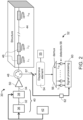
- FIG. 2 is a schematic illustration of a system 30 suitable for determining perturbation of a grating formed in an optical fiber, according to some embodiments of the present invention.
- system 30 can be used for executing at least a few of the operations of the method.
- the method begins at 10 and optionally and preferably continues to 11 at which a light beam is generated, and to 12 at which the light beam is modulated to provide a modulated light beam 34.
- the light can be infrared light, visible light or ultraviolet light as desired.
- the light is infrared light.
- the generation 11 and modulation 12 can be executed by an optical modulation system 40.
- the modulation can be either a direct modulation or an external modulation, and of any type known in the art.
- direct modulation a light source 36 receives a modulation signal from a controller 42 and generates modulated light beam 34.
- an unmodulated light beam 32 is generated by light source 36 and is modulated by an optical modulator 38 that receives the modulation signal from controller 42.
- Controller 42 can include a dedicated circuit for generating the modulation signal.
- the modulation can be at any frequency range, such as, but not limited to, radiofrequency.
- radiofrequency modulation When radiofrequency modulation is employed the modulation frequency is optionally and preferably from about 1 kHz to about 40 GHz.
- the modulation is a sinusoidal modulation, but modulation waveforms other sinusoidal are also contemplated in some embodiments.
- a multifrequency modulation is employed, for example, by a sum of sinusoidal signals, each at a different frequency.
- the modulation can be executed to modulate any of the amplitude, frequency and phase of the light beam, including modulations of two or more of the amplitude, frequency and phase.
- at least amplitude modulation is employed, and in a more preferred embodiment, only amplitude modulation is employed wherein the frequency and phase are not modulated.
- the present embodiments also contemplate modulation scanning, wherein a frequency of the modulation is scanned over a plurality of modulation frequencies.
- modulation scanning wherein a frequency of the modulation is scanned over a plurality of modulation frequencies.
- the method proceeds to 13 at which light beam 34 is amplified.
- an optical amplifier 50 such as, but not limited to, an erbium-doped fiber amplifier (EDFA), an ytterbium-doped fiber amplifier (YDFA, a Raman amplifier, a hybrid Raman/erbium-doped amplifier, a hybrid Raman/ytterbium-doped amplifier, a erbium-ytterbium co-doped fiber amplifier, a neodymium-doped fiber amplifier, a thulium-doped fiber amplifier, and the like.
- EDFA erbium-doped fiber amplifier
- YDFA ytterbium-doped fiber amplifier
- Raman amplifier a hybrid Raman/erbium-doped amplifier
- a hybrid Raman/ytterbium-doped amplifier a erbium-ytterbium co-doped fiber amplifier
- the method can proceed to 14 at which the modulated light beam 34 is transmitted through an optical fiber 44 having one or more gratings 46 formed therein, and to 15 at which light reflected off the grating(s) 46 is coupled out of optical fiber 44.
- the grating(s) can be fabricated within the entire or part of the core's cross-section or at the core-cladding interface of fiber 44, or in other fiber sections as known in the art.
- the optical fiber 44 is optionally and preferably an optical fiber with a FBG sensor or an array of FBG sensors.
- the grating 46 is constituted to selectively reflect a component of the light that has wavelengths within a particular Bragg bandwidth centered at a particular Bragg wavelength, and to allow other components to continue to propagate in the fiber 44.
- each of at least two of the gratings is constituted to selectively reflect a different component of the light.
- each grating 46 of fiber 44 is characterized by a Bragg wavelength (and a corresponding Bragg bandwidth), wherein at least two of the gratings are characterized by a different Bragg wavelength.
- Shown in FIG. 2 is a fiber with N gratings, characterized by a set of N different respective Bragg wavelengths, denoted ⁇ 1 , ⁇ 2 , ..., ⁇ N .
- the gratings need not to be ordered according to their ⁇ values.
- optical fiber 44 is deployed on or embedded within a structure such as, but not limited to, an airplane wing, a fence, a wind turbine blade, a building, a bridge, a culvert, a tunnel lining, a pipeline, a river, a flood control reservoir, a well, and the like.
- optical coupler 48 provides optical coupling between system 40 and fiber 44, and optionally and preferably also between fiber 44 and an optical and electrical analysis system generally shown at 52.
- optical coupler 48 is shown as an optical circulator having three of more input/output (I/O) ports (three shown in the present example), wherein at least one port is in optical communication with system 40 and at least one port is in optical communication with fiber 44.
- I/O input/output
- Light reflected off the grating(s) 46 propagates backwards in fiber 44, enters circulator 48 through its second port (2) and exits through its third port (3). From the third port the reflect light optionally and preferably enters system 52 for performing processing and analysis as further detailed hereinbelow.
- modulation 12 is executed after the light exits fiber 44. In these embodiments, it is not necessary to carry out modulation 12 before transmitting the light to the fiber. Yet, embodiments in which modulation 12 is applied two or more times (e.g., before the light is coupled into the fiber, and after the light exits the fiber) are also contemplated.
- the method proceeds to 16 at which the reflected light beam is dispersed.
- Operation 16 is executed so as to increase the group velocity dispersion (GVD) of the reflected light beam.
- the magnitude of the GVD of the light beam is larger (e.g., 2 times or 4 times or 8 times or 10 times larger) than the magnitude of the combined effective GVD of all the other components in system 52.
- Operation 16 is optionally and preferably performed by a dispersive optical device 54, which in some embodiments of the present invention is a component of system 52. Alternatively, or additionally, operation 16 can be performed also by the grating(s) of the fiber itself.
- dispersive optical devices suitable to be used as device 54 include, without limitation, a chirped grating formed in an optical fiber (e.g., a chirped FBG, such as, but not limited to, the chirped FBG marketed by Teraxion, Canada), a dispersion compensating fiber (DCF), and an optical fiber spool.
- a chirped grating formed in an optical fiber e.g., a chirped FBG, such as, but not limited to, the chirped FBG marketed by Teraxion, Canada
- DCF dispersion compensating fiber
- dispersive optical device it is expected that during the life of a patent maturing from this application many relevant optical devices that disperse light will be developed and the scope of the term dispersive optical device is intended to include all such new technologies a priori.
- the dispersion provided by dispersive optical device 54 is typically characterized by a dispersion coefficient ⁇ .
- the ⁇ parameter describes the amount of broadening of an optical pulse propagating in the dispersive optical device per unit of wavelength, typically in units of ps/nm.
- Suitable for the present embodiments are dispersive optical devices capable of effecting dispersion characterized by a positive or negative dispersion parameter ⁇ having an absolute value of at least 100 ps/nm or at least 300 ps/nm or at least 1000 ps/nm or at least 1500 ps/nm or at least 2000 ps/nm or at least 2500 ps/nm.
- dispersive optical device 54 is controllable, wherein the dispersion coefficient ⁇ can be varied, for example, by means of a dispersion controller 55. Variation of the dispersion coefficient can be achieved, for example, by effecting a strain on device 54 ( e.g., by applying stress or tension thereto) and/or by changing its temperature. Dispersion controller 55 is preferably a structure configured for applying stress and/or tension and/or temperature to device 45.
- the present embodiments also contemplate dispersion scanning, wherein the dispersion coefficient ⁇ is scanned over a plurality of the dispersion coefficients. The advantage of these embodiments is explained below. It is to be understood, however, that it is not necessary to employ dispersion scanning, and that the method according to some embodiments of the present invention can be practiced also when dispersive optical device 54 is characterized by a fixed value of the dispersion coefficient.
- the method optionally and preferably proceeds to 17 at which a de-multiplexing is applied to the reflected light beam.
- the de-multiplexing 17 is preferably executed to provide two or more spatially separated optical channels, each corresponding to a Bragg wavelength that characterizes a different grating of fiber 44.
- the de-multiplexing 17 can be executed using an optical de-multiplexing system 56, which can also be a component of system 52.
- De-multiplexing system 56 can be of any type, including, without limitation, an arrayed waveguide grating, a photonic crystal fiber and the like. Shown in FIG. 2 is an optical de-multiplexing system which produces N channels each corresponding to one Bragg wavelength of the aforementioned set ⁇ 1 , ⁇ 2 , ..., ⁇ N .
- the multiplicity of modulation frequencies can provide sufficient information regarding the contribution of more than one grating, as is further explained below.
- dispersion scanning in which case the multiplicity of values of the dispersion coefficients can provide sufficient information regarding the contribution of more than one grating, as is further explained below.
- the light is preferably converted into electrical signals, for example, by using an optical detector (e.g., a selector having a single optical sensor), or an array of optical detectors 58 (one for each optical channel, in embodiments in which the light is de-multiplexed into channel), and at 19 at least phase shifts in a modulation of the reflected light off the grating(s) 46 are measured, for example, by a signal processing system 60, as illustrated in FIG. 2 .
- operating 19 also includes measuring the magnitude of the signal.
- the modulation phase shift is indicative of a perturbation in the grating, and can therefore improve sensing since the phase shift is determined directly from the modulation of the light, without the need to determine a time-domain response of the signal.
- the modulation phase shifts can be determined by processing system 60 using any technique known in the art.
- a representative example of a suitable technique for determining a phase shift is provided in the Example section that follows (see Example 2).
- signal processing system 60 can comprise a network analyzer and/or a spectrum analyzer.
- processing system 60 comprises a network analyzer, it can serve both for processing the electrical signals provided by detector array 58 to determine the phase shifts, and for generating the modulation signal that is received by light source 36 or modulator 38.
- the same network analyzer can serve both as controller 42 and as signal processing system 60.
- the individual phase, wavelength or frequency shift caused by each of gratings can be determined from the information provided by the multiplicity of modulation frequencies.
- the method preferably measures, for each modulation frequency, the global phase shift and global magnitude of the reflected light. This provides a plurality of global phase shifts and a plurality of global magnitudes.
- Each global phase shift and global magnitude describes a wave formed of a plurality of partial waves, respectively corresponding to the plurality of gratings in the fiber.
- each global phase shift and global magnitude carries information regarding the individual phase, wavelength or frequency shifts caused by the gratings in the fiber.
- the number of different modulation frequencies that are employed is sufficient to extract the individual phase, wavelength or frequency shifts, and optionally also the individual magnitudes, from the global phase shifts and global magnitude. This can be done, for example, by solving a set of equations, where the unknowns are the individual phase, wavelength or frequency shifts, and the coefficients and known terms are the global phase shifts and global magnitudes. It was found by the Inventors, that for a fiber having N gratings, it is sufficient to employ N/2 different modulation frequencies. Representative example of a set of equations and a technique for automatically solve these equations is provided in the Examples section that follows (see Example. 3).
- the individual phase, wavelength or frequency shift caused by each of gratings can be determined from the information provided by the multiplicity of dispersion coefficient values.
- the method preferably measures, for each dispersion coefficient value, the global phase shift and global magnitude of the reflected light. This provides a plurality of global phase shifts and a plurality of global magnitudes, as further detailed hereinabove.
- the number of different dispersion coefficients that are employed is sufficient to extract the individual phase, wavelength or frequency shifts, and optionally also the individual magnitudes, from the global phase shifts and global magnitude. This can be done, for example, by solving a set of equations, as further detailed hereinabove, and exemplified below.
- system 60 also receives a signal from a reference light detector 62.
- Reference light detector 62 can receive a light beam that is reflected off the grating(s) but is not subjected to further dispersion and/or de-multiplexing.
- a beam splitter 57 can be placed on the optical path of the light beam exiting fiber 44 such that one beam continues as further detailed hereinabove and another beam, serving as a reference beam, is directed to detector 62.
- the method can proceed to 20 at which the perturbation of the grating is determined based on the phase shifts.
- system 40 provides a light beam that is sinusoidally modulated according to cos( ⁇ t), where ⁇ is the angular modulation frequency ( e.g., within a radiofrequency range).
- Dispersive optical device 54 disperses the light so that each component arrives separately into optical de-multiplexing system 56.
- the light component reflected from the ith grating exits dispersive optical device 54 acquiring an overall modulation phase ⁇ i , so that it is modulated according cos( ⁇ t+ ⁇ i ).
- System 56 directs each component into a separate channel, wherein the light component reflected from the ith grating is directed to the ith optical channel.
- the respective optical detector converts the ith optical channel into an electrical signal that is in turn processed by signal processing system 60 to determine its modulation parameters.
- a perturbation occurs at the ith grating so that it selectively reflects light component at wavelength ⁇ i + ⁇ i , where ⁇ i is the wavelength (within the optical range) of the light component that would have been reflected from the ith grating had this grating been unperturbed.
- the ith component acquires a modulation phase ⁇ i + ⁇ i so that it is modulated according cos( ⁇ t+ ⁇ i + ⁇ i ).
- de-multiplexing system 56 When de-multiplexing system 56 is employed, de-multiplexing system 56 directs this component into the ith optical channel, the respective optical detector converts this component into an electrical signal received by signal processing system 60. When signal processing system 60 determined that the phase of the signal generated by the ith detector is shifted, the method determines that perturbation occurred at the ith grating.
- signal processing system 60 can determine the value of the optical wavelength shift ⁇ i without de-multiplexing and without measuring its modulation phase shift proxy, for example, by employing modulation scanning as described herein. When signal processing system 60 determined that ⁇ i is non-zero the method determines that perturbation occurred at the ith grating.
- the method and system optionally and preferably successfully determine the perturbation based on the phase shift, without relying on the optical power of the reflected light beam. This is unlike conventional techniques that require complicated optical power processing operations in order to determine the perturbation.
- the perturbation as determined at 20 can be expressed in more than one way.
- the perturbation is expressed as a shift in the respective Bragg wavelength ( ⁇ i , in the above example).
- the Bragg shift can be determined, for example, using an empirically generated lookup table that relates between the modulation phase shift ⁇ i and the Bragg shift ⁇ i . From the expressed value of the Bragg shift the method can determine a value of a physical quantity effecting the perturbation of the grating, for example, as known in the art of FBG sensors.
- the perturbation is expressed as the value of the physical quantity without actually determining the Bragg shift.
- the value of the physical quantity can be determined using an empirically generated lookup table that relates between the modulation phase shift and the value of the physical quantity.
- Representative examples of physical quantities that can be determined include, without limitation, ambient temperature, pressure applied to the fiber, strain of the fiber, accelerative motion of the fiber (e.g., vibration). Another physical quantity that is contemplated is a depth of the respective grating that can be determined based on the pressure applied thereto.
- the resolution of the sensing of the Bragg shift (hence also of the value the physical quantity to be determined) can be improved by a judicious selection of the frequency of the modulation and/or the resolution of the measurement of the modulation phase shift.
- the dispersion parameter that characterizes the dispersion by ⁇ , and the modulation angular frequency by ⁇ at least one of ⁇ , ⁇ res and ⁇ is preferably selected to satisfy the relation: ⁇ res /( ⁇ ) ⁇ ⁇ res , where ⁇ res is a predetermined spectral resolution threshold.
- controller 42 can be configured to generate a modulation signal characterized by an angular modulation frequency ⁇ which is at least ⁇ res /( ⁇ res ).
- ⁇ res is less than 10 picometers or less than 1 picometers or less than 0.1 picometers or less than 0.05 picometers, e.g., 0.01 or less.
- the improvement in the spectral resolution ⁇ res (hence also the improvement in the ability to determine the value the physical quantity) can be achieved without or with small compromise on the speed of the measurement.
- the speed of the measurement is typically expressed in terms of the sampling rate employed by signal processing system 60 in determining the modulation phase shifts.
- at least one of ⁇ , ⁇ res and ⁇ is selected to provide spectral resolution of ⁇ res that less than 0.1 picometer or less than 0.05 picometers, e.g., 0.01 or less, at a sampling rate signal processing system 60 that is at least 1 kHz or at least 10 kHz or at least 100 kHz or at least 1 MHz or at least 10 MHz.
- compositions, method or structure may include additional ingredients, steps and/or parts, but only if the additional ingredients, steps and/or parts do not materially alter the basic and novel characteristics of the claimed composition, method or structure.
- range format is merely for convenience and brevity and should not be construed as an inflexible limitation on the scope of the invention. Accordingly, the description of a range should be considered to have specifically disclosed all the possible subranges as well as individual numerical values within that range. For example, description of a range such as from 1 to 6 should be considered to have specifically disclosed subranges such as from 1 to 3, from 1 to 4, from 1 to 5, from 2 to 4, from 2 to 6, from 3 to 6 etc., as well as individual numbers within that range, for example, 1, 2, 3, 4, 5, and 6. This applies regardless of the breadth of the range.
- This Example demonstrates a high speed and high sensitivity FBG interrogator based on radio frequency (RF) phase-shift measurement.
- RF radio frequency
- This Example uses direct RF phase-shift measurements as the basis for the interrogation of wavelength shifts in an FBG sensor. The unique potential of this method for achieving an excellent resolution-speed tradeoff, e,g, 10 MHz speed with 1 pm spectral resolution, is demonstrated.
- the signal After passing through a dispersive medium with a dispersion coefficient D [ ps / nm / km ] and length L, the signal acquires a group delay ⁇ g which can be expressed as an additional phase ⁇ in the AC term:
- FIG. 3 The experimental setup used in this demonstration is illustrated in FIG. 3 .
- a superluminescent diode (SLED) in the c-band was directly modulated with an RF signal of a vector network analyzer (VNA) having a tunable RF filter.
- VNA vector network analyzer
- the modulated light was amplified by an EDFA and directed with a circulator into a sensing channel having three FBGs with different Bragg wavelengths.
- DCM dispersion compensating module
- DCF dispersion compensating fiber
- a demultiplexer split the light into three spectral regimes corresponding to the Bragg wavelengths of the three FBGs, and the detected signals were then routed back to the VNA for RF phase-shift measurement.
- the average detected optical power was approximately -16 dBm.
- the system's performance with weak strain was demonstrated.
- One of the FBGs was periodically strained with a motorized high-precision mechanical stage at a frequency of approximately 1 Hz, and the signal was sampled at a rate of 10 Hz.
- the pk-pk strain on the FBG was approximately 0.09 ⁇ , giving a spectral shift of about 0.1 pm in the Bragg wavelength.
- the output signal is shown in FIG. 4 , demonstrating the capability of the system of the present embodiments to acquire weak strain signals with good SNR. The shown resolution capability is below 0.1 pm.
- a second experiment demonstrated the system response in an ultrasonic region between 20-100 kHz.
- a second FBG was immersed in a water-filled container, together with an ultrasonic probe (Sonics Vibra-Cell) which gives a fixed vibration at 20 kHz.
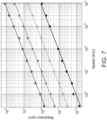
- the Fast Fourier transform (FFT) of the acquired signal is shown in FIG. 5 for three different values of the ultrasonic-wave intensity.
- the green line corresponds to 20% ultrasonic power
- the red line corresponds to 60% ultrasonic power
- the black line corresponds to 80% ultrasonic power.
- the red and black lines are offset for clarity. Note that as the intensity increases, the second harmonic at 40 kHz appears, and for higher intensity other frequencies appear, due to the nonlinearity of the probe.
- the y-axis wavelength-shift values ( ⁇ ) refer only to the low intensity level experiment (20%), the others are at the same scale, but shifted for clarity.
- the speed acquisition was about 70 kHz for the low level experiment and about 96 kHz for the higher levels, in order to record the higher harmonic vibrations.
- FIG. 6 shows the results of a third experiment, where a third FBG was wound around a piezoelectric fiber stretcher (Optiphase) driven by a sinusoidal signal at 200 kHz.
- the acquisition speed was set at about 1.4 MHz.
- a graph of the signal FFT shows the 200 kHz peak, corresponding to am about 3.5 pm shift in the Bragg wavelength, with an SNR of about 7.
- the spectral dynamic range (ratio between spectral bandwidth and resolution) of the exemplified technique is about 35dB for phase resolution of 2 mrad, within the 2 ⁇ phase ambiguity constraint.
- the flexibility of the technique of the present embodiments is an advantage, since decreasing the modulation frequency decreases the wavelength-shift to phase-shift ratio (see EQ. 3), allowing for large wavelength range measurements.
- the phase can in some embodiments of the present invention be unwrapped by digital signal processing if the sampling rate is at least twice as fast as the signal measurement speed, enabling an increase of the dynamic range.
- the large spectral dynamic range and flexible wavelength range measurement allow for high-speed and high-resolution interrogation.
- ASE amplified spontaneous emission
- a further advantage of the technique of the present embodiments is the ability to simultaneously interrogate cascaded FBG sensors by routing the different spectral regions of each FBG sensor to different detectors (for example, using a demultiplexer) and measuring all the phase-shifts in parallel. This capability is particularly useful for applications such as machine condition monitoring, especially at MHz sampling rates.
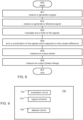
- FIG. 8 is a flowchart diagram of a method suitable for amplifying a phase shift of a signal relative to a reference signal, according to some embodiments of the present invention.
- the method is suitable for improving the resolution of phase shift measurement.
- the phase shift can be amplified by a predetermined factor to a value that is within the detection resolution of a phase shift detector.
- the amplified phase shift can then be measured by the phase shift detector as known in the art, and the result of the measurement can be divided by the predetermined factor, thereby allowing the determination of the unamplified phase shift even if its extent is less than the available resolution of the phase shift detector.
- the method begins at 600 and continues to 601 at which a signal S is generated or received, and to 602 at which a reference signal S ref is generated or received.
- a signal S can be the signal reflected off the grating(s) in the fiber of the present embodiments, and the other signal (e.g., signal S ref ) can be received via a path that does not allow it to interact with the grating(s).
- the method continues to 603 at which the modulation of at least one of the signals is varied. The variation is optionally and preferably with respect to the modulation amplitude such that the modulation amplitudes of the signal and the reference signal are sufficiently close to each other.
- a ratio between modulation amplitudes of the signal and the reference signal is from about 0.9 to about 1.1, or from about 0.95 to about 1.05, or from about 0.99 to about 1.01, or from about 0.995 to about 1.005, or from about 0.999 to about 1.001 or from about 0.9995 to about 1.0005 or from about 0.9999 to about 1.0001.
- the variation is optionally and preferably also with respect to the modulation phase, such that such that the phase difference ⁇ in between the phase ⁇ 1 of the reference signal and the phase ⁇ 2 of the signal is sufficiently small or sufficiently close to ⁇ radians, as further detailed hereinabove.
- one of signals S and S ref is generated by selected operations of method 100 so as to ensure that the phase difference ⁇ in is sufficiently small or sufficiently close to ⁇ radians.
- the amplitude(s) and phase(s) employed for the modulation variation can be selected by the method or be stored or encoded in a circuit that vary the modulation.
- the method preferably continues to 604 at which an output signal S out which is a linear combination of the signals is formed.
- This can be done electronically, using an electric circuit, or optically using an optical assembly.
- the combination 604 can be done either directly, for example, using a signal summing circuit, or indirectly, for example, by signal multiplication followed by extraction of signal components that are linearly proportional to each of the signals, as further detailed hereinabove.
- the normalization parameter p can be set to any number, e.g., 1.
- the linear combination coefficient reflects the weight ratio of the two signal and is optionally and preferably selected based on the sign of cos( ⁇ in ), where ⁇ in is the phase difference between the modulation phases of the signals.
- q is about 1 when cos( ⁇ in ) is negative and about -1 when cos( ⁇ in ) is positive.
- NINT is the nearest integer function and the ⁇ sign is to be understood as within 10%.
- ⁇ can be at most 0.1 or at most 0.05 or at most 0.01 or at most 0.005 or at most 0.0001 or less, so that ⁇ out can be 10 times larger or 20 times larger or 100 times larger or 200 times larger or 1000 times larger or 2000 times larger or 10000 times larger than ⁇ in , where ⁇ out is the phase of S out .
- the method continues to 605 at which the phase of the output signal relative to the reference signal is measured.
- This can be done using any phase measuring technique known in the art. Representative examples including, without limitation, phase detectors that are commercially available from Mini-Circuits°, USA, and On Semiconductors ® , USA.
- the method continues to 606 at which a change over time of the phase of the output signal relative to the reference signal is measured.
- Operation 606 can be executed whether or not the phase of the output signal is known, since a change in a phase of a signal can be measured even when the signal's phase itself is not known.
- 605 is executed and 606 is not executed, in some embodiments both 605 and 606 are executed, in some embodiments 605 is not executed and 606 is executed, and in some embodiments none of 605 and 606 is executed.
- FIG. 9 is a schematic block diagram illustration of a system 700 for amplifying a phase shift of a signal relative to a reference signal, according to some embodiments of the present invention.
- System 700 is optionally and preferably configured for executing one or more operations of method 600 above.
- System 700 comprises a modulation circuit 702, configured for varying a modulation of at least one of the signals as further detailed hereinabove.
- the amplitude(s) and phase(s) employed for the modulation variation performed by circuit 702 can be selected by system 700, for example, using an amplitude selection circuit, or be stored or encoded in circuit 702.
- System 700 can also comprise a signal combiner 704, configured for forming an output signal S out which is a linear combination of the signals, as further detailed hereinabove.
- combiner 704 comprises a signal multiplier circuit. These embodiments are useful when the linear combination is obtained by multiplication followed by extraction of linear components as further detailed hereinabove.
- combiner 704 is an optical assembly configured for performing a linear combination of two signals as known in the art.
- system 700 comprises a detector circuit 706, which can be configured as phase detector for measuring a phase of the output signal relative to the reference signal, or as a phase-change detector for measuring a change of phase of the output signal over time, or as a combined phase detector and phase-change detector for measuring both the phase of and its change.
- a detector circuit 706 can be configured as phase detector for measuring a phase of the output signal relative to the reference signal, or as a phase-change detector for measuring a change of phase of the output signal over time, or as a combined phase detector and phase-change detector for measuring both the phase of and its change.
- This Example describes a technique for numerically calculating the wavelength-shift caused by each grating, by scanning the modulation frequency.
- This system of equations can be automatically solved using any technique known in the art. Representative examples include, without limitation the 'Trust-region' method [26] and the 'Levenberg-Marguardt' technique [27,28].
Landscapes
- Physics & Mathematics (AREA)
- General Physics & Mathematics (AREA)
- Optics & Photonics (AREA)
- Optical Transform (AREA)
- Testing Of Optical Devices Or Fibers (AREA)
- Light Guides In General And Applications Therefor (AREA)
- Investigating Or Analysing Materials By Optical Means (AREA)
- Spectrometry And Color Measurement (AREA)
Applications Claiming Priority (3)
| Application Number | Priority Date | Filing Date | Title |
|---|---|---|---|
| US201862693941P | 2018-07-04 | 2018-07-04 | |
| EP19830499.0A EP3818331B1 (de) | 2018-07-04 | 2019-07-04 | Verfahren und system zur feststellung von gitterstörung durch moduliertes licht |
| PCT/IL2019/050742 WO2020008464A1 (en) | 2018-07-04 | 2019-07-04 | Method and system for determining grating perturbation by modulated light |
Related Parent Applications (1)
| Application Number | Title | Priority Date | Filing Date |
|---|---|---|---|
| EP19830499.0A Division EP3818331B1 (de) | 2018-07-04 | 2019-07-04 | Verfahren und system zur feststellung von gitterstörung durch moduliertes licht |
Publications (2)
| Publication Number | Publication Date |
|---|---|
| EP4400811A2 true EP4400811A2 (de) | 2024-07-17 |
| EP4400811A3 EP4400811A3 (de) | 2024-09-04 |
Family
ID=69060799
Family Applications (2)
| Application Number | Title | Priority Date | Filing Date |
|---|---|---|---|
| EP24171394.0A Pending EP4400811A3 (de) | 2018-07-04 | 2019-07-04 | Verfahren und system zur bestimmung von gitterstörungen durch moduliertes licht |
| EP19830499.0A Active EP3818331B1 (de) | 2018-07-04 | 2019-07-04 | Verfahren und system zur feststellung von gitterstörung durch moduliertes licht |
Family Applications After (1)
| Application Number | Title | Priority Date | Filing Date |
|---|---|---|---|
| EP19830499.0A Active EP3818331B1 (de) | 2018-07-04 | 2019-07-04 | Verfahren und system zur feststellung von gitterstörung durch moduliertes licht |
Country Status (8)
| Country | Link |
|---|---|
| US (1) | US11698277B2 (de) |
| EP (2) | EP4400811A3 (de) |
| JP (1) | JP7383644B2 (de) |
| CN (1) | CN112469958A (de) |
| DK (1) | DK3818331T3 (de) |
| ES (1) | ES2986395T3 (de) |
| IL (1) | IL279954B (de) |
| WO (1) | WO2020008464A1 (de) |
Families Citing this family (5)
| Publication number | Priority date | Publication date | Assignee | Title |
|---|---|---|---|---|
| CN112469958A (zh) | 2018-07-04 | 2021-03-09 | 阿里尔科学创新有限公司 | 通过调制光来确定光栅微扰的方法及系统 |
| JP7711063B2 (ja) | 2019-12-20 | 2025-07-22 | アリエル サイエンティフィック イノベーションズ リミテッド | 光信号から情報を抽出する方法及びシステム |
| FR3111980B1 (fr) * | 2020-06-25 | 2022-07-01 | Safran | Procede et dispositif de mesure physique de conditions environnementales et opérationnelles |
| CN114137273B (zh) * | 2021-11-30 | 2023-11-28 | 哈尔滨理工大学 | Fbg级联光纤复合结构的消除温度敏感电流传感装置 |
| IT202400003457A1 (it) | 2024-02-19 | 2025-08-19 | Vincenzo Romano Marrazzo | Sistema multicanale per misure compensate di sensori in fibra ottica completamente analogico |
Citations (1)
| Publication number | Priority date | Publication date | Assignee | Title |
|---|---|---|---|---|
| US20140152995A1 (en) * | 2012-11-27 | 2014-06-05 | Sentek Instrument LLC | Serial weak fbg interrogator |
Family Cites Families (28)
| Publication number | Priority date | Publication date | Assignee | Title |
|---|---|---|---|---|
| DE3743678A1 (de) | 1987-12-23 | 1989-07-06 | Philips Patentverwaltung | Optisches rueckstreumessgeraet |
| US5426297A (en) * | 1993-09-27 | 1995-06-20 | United Technologies Corporation | Multiplexed Bragg grating sensors |
| US5675674A (en) * | 1995-08-24 | 1997-10-07 | Rockbit International | Optical fiber modulation and demodulation system |
| US5748312A (en) * | 1995-09-19 | 1998-05-05 | United States Of American As Represented By The Secretary Of The Navy | Sensing apparatus and method for detecting strain between fiber bragg grating sensors inscribed into an optical fiber |
| KR100496554B1 (ko) | 1996-06-28 | 2005-11-08 | 더 거번먼트 오브 더 유나이티드 스테이츠 오브 아메리카, 애즈 레프리젠티드 바이 더 세크러테리 오브 더 네이비 네이벌 리서치 래보러토리 | 브래그격자센서를이용한광학센서시스템 |
| US5680489A (en) * | 1996-06-28 | 1997-10-21 | The United States Of America As Represented By The Secretary Of The Navy | Optical sensor system utilizing bragg grating sensors |
| DE19821616B4 (de) * | 1998-05-15 | 2009-05-14 | Institut Für Photonische Technologien E.V. | Anordnung zur Bestimmung von absoluten physikalischen Zustandsgrößen, insbesondere Temperatur und Dehnung, einer optischen Faser |
| US6285806B1 (en) | 1998-05-31 | 2001-09-04 | The United States Of America As Represented By The Secretary Of The Navy | Coherent reflectometric fiber Bragg grating sensor array |
| AU2001283043A1 (en) * | 2000-08-01 | 2002-02-13 | The Government Of The United States Of America, As Represented By The Secretary Of The Navy | Optical sensing device containing fiber bragg gratings |
| US6785004B2 (en) * | 2000-11-29 | 2004-08-31 | Weatherford/Lamb, Inc. | Method and apparatus for interrogating fiber optic sensors |
| US6836578B2 (en) * | 2003-04-14 | 2004-12-28 | Lake Shore Cryotronics, Inc. | System and method for measuring physical stimuli using vertical cavity surface emitting lasers with integrated tuning means |
| GB0415881D0 (en) | 2004-07-15 | 2004-08-18 | Univ Southampton | Multiwavelength optical sensors |
| JP5469861B2 (ja) * | 2005-04-14 | 2014-04-16 | コーネル リサーチ ファウンデーション,インコーポレーティッド | チャープパルスファイバ増幅器 |
| JP2008020342A (ja) | 2006-07-13 | 2008-01-31 | Yokogawa Denshikiki Co Ltd | 外力検出装置 |
| JP4698746B2 (ja) * | 2009-04-23 | 2011-06-08 | 富士通株式会社 | 波長分散補償器 |
| EP2614344B1 (de) * | 2010-09-08 | 2017-04-12 | The Board of Trustees of the Leland Stanford Junior University | Faser-bragg-gittersensor mit langsamem licht |
| US9025157B2 (en) * | 2010-09-08 | 2015-05-05 | The Board Of Trustees Of The Leland Stanford Junior University | System and method for measuring perturbations using a slow-light fiber Bragg grating sensor |
| GB2508376A (en) | 2012-11-29 | 2014-06-04 | Ibm | Optical spectrometer comprising an adjustably strained photodiode |
| CN103344194B (zh) * | 2013-07-17 | 2015-07-15 | 中国科学院半导体研究所 | 基于光电振荡器的相移光纤布拉格光栅应变传感系统 |
| US9583796B2 (en) | 2014-04-01 | 2017-02-28 | Palo Alto Research Center Incorporated | Method for monitoring/managing electrochemical energy device by detecting intercalation stage changes |
| FR3031590B1 (fr) | 2015-01-09 | 2017-01-13 | Thales Sa | Capteur a fibre optique |
| CN105333815B (zh) * | 2015-11-05 | 2018-04-10 | 北京交通大学 | 一种基于光谱色散线扫描的超横向分辨率表面三维在线干涉测量系统 |
| EP3371546A4 (de) * | 2015-11-06 | 2019-05-08 | AP Robotics, LLC | Interferometrische entfernungsmessung auf der grundlage von kompressions- von gechirptem interferogramm aus kreuzgechirpter interferenz |
| CN106100748B (zh) | 2016-05-27 | 2018-10-16 | 西安电子科技大学 | 利用相位调制器和可调谐色散器生成微波波形的方法 |
| CN107947867B (zh) | 2017-12-05 | 2019-12-13 | 安徽工程大学 | 一种基于多频相位调制的单边带频谱产生装置及方法 |
| CN112262342B (zh) | 2018-03-09 | 2024-11-12 | 拉瓦尔大学 | 光相位调制器和光调制器 |
| CN112469958A (zh) | 2018-07-04 | 2021-03-09 | 阿里尔科学创新有限公司 | 通过调制光来确定光栅微扰的方法及系统 |
| JP7711063B2 (ja) | 2019-12-20 | 2025-07-22 | アリエル サイエンティフィック イノベーションズ リミテッド | 光信号から情報を抽出する方法及びシステム |
-
2019
- 2019-07-04 CN CN201980046270.7A patent/CN112469958A/zh active Pending
- 2019-07-04 ES ES19830499T patent/ES2986395T3/es active Active
- 2019-07-04 US US17/256,664 patent/US11698277B2/en active Active
- 2019-07-04 DK DK19830499.0T patent/DK3818331T3/da active
- 2019-07-04 EP EP24171394.0A patent/EP4400811A3/de active Pending
- 2019-07-04 EP EP19830499.0A patent/EP3818331B1/de active Active
- 2019-07-04 IL IL279954A patent/IL279954B/en unknown
- 2019-07-04 JP JP2020569076A patent/JP7383644B2/ja active Active
- 2019-07-04 WO PCT/IL2019/050742 patent/WO2020008464A1/en not_active Ceased
Patent Citations (1)
| Publication number | Priority date | Publication date | Assignee | Title |
|---|---|---|---|---|
| US20140152995A1 (en) * | 2012-11-27 | 2014-06-05 | Sentek Instrument LLC | Serial weak fbg interrogator |
Non-Patent Citations (29)
| Title |
|---|
| A. A. GIORDANAE. E. SICRER. DUCHOWICZ: "Simple wavelength-to-phase mapping FBG's interrogation method", OPTICS AND LASERS IN ENGINEERING, vol. 55, 2014, pages 221 - 225 |
| A. D. KERSEYT. A. BERKOFFW. W. MOREY: "High-resolution fiber-grating based strain sensor with interferometric wavelength-shift detection", ELECTRONICS LETT., vol. 28, no. 3, 1992, pages 236 - 238, XP000305957 |
| A. IKEDAT. NOMURAY.H. MATSUDAS. TANIY. KOBAYASHIH. WATANANDK. SATO: "High-speed 100 MHz strain monitor using fiber Bragg grating and optical filter for magnetostriction measurements under ultrahigh magnetic fields", REV. SCI. INSTRUM., vol. 88, 2017, pages 083906, XP012221645, DOI: 10.1063/1.4999452 |
| B. COSTAD. MAZZONIM. PULEOE. VEZZONI: "Phase shift technique for the measurement of chromatic dispersion in optical fibers using LED's", IEEE J. QUANTUM ELECTRON. QE, vol. 18, no. 10, 1982, pages 1509 - 1515 |
| C. WANGJ. YAO: "Ultrafast and ultrahigh-resolution interrogation of a fiber Bragg grating sensor based on interferometric temporal spectroscopy", J. LIGHTWAVE TECHNOL., vol. 29, no. 19, 2011, pages 2927 - 2933, XP011360053, DOI: 10.1109/JLT.2011.2164572 |
| CHEN ET AL.: "Review of fiber Bragg grating sensor technology", FRONT. OPTOELECTRON, vol. 4, 2011, pages 204, XP019911921, DOI: 10.1007/s12200-011-0130-4 |
| D. MARQUARDT: "An Algorithm for Least-Squares Estimation of Nonlinear Parameters", SIAM J. APPL.MATH., vol. 11, 1963, pages 431 - 441, XP000677023, DOI: 10.1137/0111030 |
| G. HERINKB. JALALIC. ROPERSD. R. SOLLI: "Resolving the build-up of femtosecond mode-locking with single-shot spectroscopy at 90MHz frame rate", NATURE PHOTONICS, vol. 10, 2016, pages 321 - 326 |
| H. CHI AND J. YAO: "Fiber chromatic dispersion measurement based on wavelength-to-time mapping using a femtosecond pulse laser and an optical comb filter", COMMUNICATIONS, vol. 280, no. 2, 2007, pages 337 - 342, XP022314996, DOI: 10.1016/j.optcom.2007.08.059 |
| H. FUW. ZHANGC. MOUX. SHUL. ZHANGS. HEI. BENNION: "High-Frequency Fiber Bragg Grating Sensing Interrogation System Using Sagnac-Loop-Based Microwave Photonic Filtering", IEEE PHOTONICS TECH. LETT., vol. 21, no. 8, 2009, pages 519, XP011250687 |
| H. XIA, C. WANG, S. BLAIS, AND J. YAO: "Ultrafast and Precise Interrogation of Fiber Bragg Grating Sensor Based on Wavelength-to-Time Mapping Incorporating Higher Order Dispersion", J. LIGHTWAVE. TECHNOL., vol. 28, no. 3, 2010, pages 254 - 261, XP011285802, DOI: 10.1109/JLT.2009.2037722 |
| H.Y. FUH.L. LIUX. DONGH.Y. TAMP.K.A. WAIC. LU: "High-speed fibre Bragg grating sensor interrogation using dispersion compensation fiber", ELECTRINCS LETT, vol. 44, no. 10, 2008, pages 618 - 619, XP006031076, DOI: 10.1049/EL:20080859 |
| J. C. BELLIDOC. R. FERNANDEZ-POUSA: "Spectral Analysis Using a Dispersive Microwave Photonics Link Based on a Broadband Chirped Fiber Bragg Grating", J. LIGHTWAVE. TECHNOL., vol. 33, no. 20, 2015, pages 4207 - 14, XP011668873, DOI: 10.1109/JLT.2015.2466680 |
| J. CHEN, B. LIU AND H. ZHANG: "Review of fiber Bragg grating sensor technology", OPTOELECTRON. CHINA, vol. 4, 2011, pages 204, XP019911921, DOI: 10.1007/s12200-011-0130-4 |
| J. CHOUB. JALALID. R. SOLLI: "Amplified wavelength-time transformation for real-time spectroscopy", NATURE PHOTONICS, vol. 2, no. 1, 2008, pages 48 - 51, XP055216135, DOI: 10.1038/nphoton.2007.253 |
| J. CHOUY. HANB. JALALI: "Time-wavelength spectroscopy for chemical sensing", IEEE PHOTONICS TECH. LETT., vol. 16, no. 4, 2004, pages 1140 - 2, XP011110315, DOI: 10.1109/LPT.2004.824997 |
| J. FRIEDENJ. CUGNONIJ. BOTSIST. GMURD.CORIC: "High-speed internal strain measurements in composite structures under dynamic load using embedded FBG sensors", COMPOS. STRUCT., vol. 92, 2010, pages 1905 - 1912, XP026965332 |
| J. HERVASC. R. FERNANDEZ-POUSAD. BARRERAD. PASTORS. SALESJ. CAPMANY: "An interrogation technique of FBG cascade sensors using wavelength to radio-frequency delay mapping", J. LIGHTWAVE. TECHNOL., vol. 33, no. 11, 2015, pages 2222 - 7, XP011576425, DOI: 10.1109/JLT.2015.2409318 |
| J. PARKW.V. SORINK.Y. LAU: "Elimination of the fibre chromatic dispersion penalty on 1550nm millimeter-wave optical transmission", ELECTRONICS LETT., vol. 33, 1997, pages 512 - 3 |
| J. ZHOUL. XIAR. CHENGYY. WENJ. ROHOLLAHNEJAD: "Radio-frequency unbalanced M-Z interferometer for wavelength interrogation of fiber Bragg grating sensors", OPT. LETT., vol. 41, no. 2, 2016, pages 313 - 316 |
| K. LEVENBERG: "A Method for the Solution of Certain Problems in Least Squares", APPL.MATH., vol. 2, 1944, pages 164 - 168 |
| LEI, M., ZOU, W., LI, X. & CHEN: "Ultrafast FBG interrogator based on time-stretch method.", IEEE PHOTON. TECHNOL. LETT., vol. 28, 2016, pages 778 - 781, XP011600495, DOI: 10.1109/LPT.2015.2513903 |
| P. V. KELKAR, F. COPPINGER, A. S. BHUSHAN AND B. JALALI: "Time-domain optical sensing", ELECTRONICS LETTERS, vol. 35, no. 19, 1999, pages 1661 - 2, XP006012694, DOI: 10.1049/el:19991116 |
| R. D. SANTE: "Fibre Optic Sensors for Structural Health Monitoring of Aircraft Composite Structures: Recent Advances and Applications", SENSORS, vol. 15, 2015, pages 18666 - 18713, XP055390297, DOI: 10.3390/s150818666 |
| W. W. MOREY, J. R. DUNPHY AND G. MELTZ: "Multiplexing fiber Bragg grating sensors", FIBER AND INTEGRATED OPTICS, vol. 10, 1992, pages 351 - 360, XP000619148 |
| X DONGLY SHAOHY FUHY TAMC. LU: "FBG sensor interrogation based on RF signal measurement", PROC. OF SPIE 7004 700423, 2008 |
| Y. C. TONGL. Y. CHANH. K. TSANG: "Fibre dispersion or pulse spectrum measurement using a sampling oscilloscope", ELECTRONICS LETT., vol. 33, no. 11, 1997, pages 983 - 985, XP006007525, DOI: 10.1049/el:19970663 |
| Y. WANGM. HANA. WANG: "High-speed fiber-optic spectrometer for signal demodulation of inteferometric fiber-optic sensors", OPT. LETT., vol. 31, 2006, pages 2408 - 10, XP001245252, DOI: 10.1364/OL.31.002408 |
| Y. YUAN: "Recent Advances in Trust Region Algorithms.", MATH. PROGRAM., vol. 151, 2015, pages 249 - 281, XP035503083, DOI: 10.1007/s10107-015-0893-2 |
Also Published As
| Publication number | Publication date |
|---|---|
| EP3818331B1 (de) | 2024-04-24 |
| WO2020008464A1 (en) | 2020-01-09 |
| JP7383644B2 (ja) | 2023-11-20 |
| EP3818331A4 (de) | 2022-03-23 |
| US20210262835A1 (en) | 2021-08-26 |
| CN112469958A (zh) | 2021-03-09 |
| ES2986395T3 (es) | 2024-11-11 |
| US11698277B2 (en) | 2023-07-11 |
| EP3818331A1 (de) | 2021-05-12 |
| IL279954A (en) | 2021-03-01 |
| JP2021529300A (ja) | 2021-10-28 |
| IL279954B (en) | 2022-08-01 |
| EP4400811A3 (de) | 2024-09-04 |
| DK3818331T3 (da) | 2024-07-29 |
Similar Documents
| Publication | Publication Date | Title |
|---|---|---|
| EP3818331B1 (de) | Verfahren und system zur feststellung von gitterstörung durch moduliertes licht | |
| US20070058897A1 (en) | Fiber bragg grating sensor system | |
| WO2013185810A1 (en) | A sensing system and method for distributed brillouin sensing | |
| Bergman et al. | Dynamic and distributed slope-assisted fiber strain sensing based on optical time-domain analysis of Brillouin dynamic gratings | |
| KR101889351B1 (ko) | 유효 측정점 개수가 확대된 공간선택적 브릴루앙 분포형 광섬유 센서 및 브릴루앙 산란을 이용한 센싱 방법 | |
| Lei et al. | Ultrafast FBG interrogator based on time-stretch method | |
| Tanaka et al. | Multipoint fiber Bragg grating sensing using two-photon absorption process in Silicon avalanche photodiode | |
| JP6290798B2 (ja) | Ofdr装置 | |
| US11391645B2 (en) | Birefringent multi-peak optical reference element and birefringent sensor system | |
| Glasser et al. | High speed and high sensitivity fiber Bragg grating interrogator based on the RF phase-shift technique | |
| Fujisue et al. | Demodulation of acoustic signals in fiber Bragg grating ultrasonic sensors using arrayed waveguide gratings | |
| JP6085573B2 (ja) | 分岐光線路の特性解析装置および分岐光線路の特性解析方法 | |
| KR20160122319A (ko) | 다중 광원을 이용한 광섬유 브릴루앙 시간영역해석 센서 및 그 센싱방법 | |
| Jeon et al. | Optical fiber chromatic dispersion measurement using bidirectional modulation of an optical intensity modulator | |
| Nureev et al. | Combined Brillouin sensor system for simultaneous local and distributed temperature and strain measurements for downhole telemetry | |
| RU2413259C1 (ru) | Способ регистрации сигналов измерительных преобразователей на основе брэгговских решеток, записанных в едином волоконном световоде | |
| EP3335014B1 (de) | Lichtwellenleiter-sensor-system | |
| Lei et al. | High-resolution micro-displacement measurement using a fiber MZI based on microwave photonics filter | |
| Hua et al. | Distributed optical fiber sensing based on coherence-length gated microwave photonics interferometry | |
| Giordana et al. | Simple wavelength-to-phase mapping FBG's interrogation method | |
| Zhou et al. | Low coherent optical frequency domain reflectometry interrogates fiber Bragg grating sensors | |
| Yildiz et al. | Distributed sensing using frequency-selective fading | |
| Muanenda et al. | A High-SNR Distributed Acoustic Sensor Based on ϕ-OTDR Using a Scalable Phase Demodulation Scheme Without Phase Unwrapping | |
| JP5179277B2 (ja) | 波長分散測定装置及び波長分散測定方法 | |
| Shinoda et al. | Real-time measurement of multi-point strain by fiber Bragg gratings using optical frequency sweeping |
Legal Events
| Date | Code | Title | Description |
|---|---|---|---|
| PUAI | Public reference made under article 153(3) epc to a published international application that has entered the european phase |
Free format text: ORIGINAL CODE: 0009012 |
|
| STAA | Information on the status of an ep patent application or granted ep patent |
Free format text: STATUS: REQUEST FOR EXAMINATION WAS MADE |
|
| 17P | Request for examination filed |
Effective date: 20240419 |
|
| AC | Divisional application: reference to earlier application |
Ref document number: 3818331 Country of ref document: EP Kind code of ref document: P |
|
| AK | Designated contracting states |
Kind code of ref document: A2 Designated state(s): AL AT BE BG CH CY CZ DE DK EE ES FI FR GB GR HR HU IE IS IT LI LT LU LV MC MK MT NL NO PL PT RO RS SE SI SK SM TR |
|
| REG | Reference to a national code |
Ref country code: DE Ref legal event code: R079 Free format text: PREVIOUS MAIN CLASS: G01D0005353000 Ipc: G01B0009020000 |
|
| PUAL | Search report despatched |
Free format text: ORIGINAL CODE: 0009013 |
|
| AK | Designated contracting states |
Kind code of ref document: A3 Designated state(s): AL AT BE BG CH CY CZ DE DK EE ES FI FR GB GR HR HU IE IS IT LI LT LU LV MC MK MT NL NO PL PT RO RS SE SI SK SM TR |
|
| RIC1 | Information provided on ipc code assigned before grant |
Ipc: G01D 5/353 20060101ALI20240801BHEP Ipc: G02B 6/34 20060101ALI20240801BHEP Ipc: G02B 6/26 20060101ALI20240801BHEP Ipc: G01B 9/02 20220101AFI20240801BHEP |
|
| STAA | Information on the status of an ep patent application or granted ep patent |
Free format text: STATUS: EXAMINATION IS IN PROGRESS |
|
| 17Q | First examination report despatched |
Effective date: 20250701 |