EP4400752A2 - Verfahren zum testen eines ein-/auslassventils - Google Patents
Verfahren zum testen eines ein-/auslassventils Download PDFInfo
- Publication number
- EP4400752A2 EP4400752A2 EP24170772.8A EP24170772A EP4400752A2 EP 4400752 A2 EP4400752 A2 EP 4400752A2 EP 24170772 A EP24170772 A EP 24170772A EP 4400752 A2 EP4400752 A2 EP 4400752A2
- Authority
- EP
- European Patent Office
- Prior art keywords
- valve
- inlet
- gas
- pressure
- outlet
- Prior art date
- Legal status (The legal status is an assumption and is not a legal conclusion. Google has not performed a legal analysis and makes no representation as to the accuracy of the status listed.)
- Granted
Links
Images





Classifications
-
- F—MECHANICAL ENGINEERING; LIGHTING; HEATING; WEAPONS; BLASTING
- F02—COMBUSTION ENGINES; HOT-GAS OR COMBUSTION-PRODUCT ENGINE PLANTS
- F02M—SUPPLYING COMBUSTION ENGINES IN GENERAL WITH COMBUSTIBLE MIXTURES OR CONSTITUENTS THEREOF
- F02M65/00—Testing fuel-injection apparatus, e.g. testing injection timing ; Cleaning of fuel-injection apparatus
-
- F—MECHANICAL ENGINEERING; LIGHTING; HEATING; WEAPONS; BLASTING
- F02—COMBUSTION ENGINES; HOT-GAS OR COMBUSTION-PRODUCT ENGINE PLANTS
- F02M—SUPPLYING COMBUSTION ENGINES IN GENERAL WITH COMBUSTIBLE MIXTURES OR CONSTITUENTS THEREOF
- F02M65/00—Testing fuel-injection apparatus, e.g. testing injection timing ; Cleaning of fuel-injection apparatus
- F02M65/006—Measuring or detecting fuel leakage of fuel injection apparatus
-
- F—MECHANICAL ENGINEERING; LIGHTING; HEATING; WEAPONS; BLASTING
- F16—ENGINEERING ELEMENTS AND UNITS; GENERAL MEASURES FOR PRODUCING AND MAINTAINING EFFECTIVE FUNCTIONING OF MACHINES OR INSTALLATIONS; THERMAL INSULATION IN GENERAL
- F16K—VALVES; TAPS; COCKS; ACTUATING-FLOATS; DEVICES FOR VENTING OR AERATING
- F16K37/00—Special means in or on valves or other cut-off apparatus for indicating or recording operation thereof, or for enabling an alarm to be given
- F16K37/0075—For recording or indicating the functioning of a valve in combination with test equipment
- F16K37/0091—For recording or indicating the functioning of a valve in combination with test equipment by measuring fluid parameters
-
- G—PHYSICS
- G01—MEASURING; TESTING
- G01M—TESTING STATIC OR DYNAMIC BALANCE OF MACHINES OR STRUCTURES; TESTING OF STRUCTURES OR APPARATUS, NOT OTHERWISE PROVIDED FOR
- G01M13/00—Testing of machine parts
- G01M13/003—Machine valves
-
- G—PHYSICS
- G01—MEASURING; TESTING
- G01M—TESTING STATIC OR DYNAMIC BALANCE OF MACHINES OR STRUCTURES; TESTING OF STRUCTURES OR APPARATUS, NOT OTHERWISE PROVIDED FOR
- G01M3/00—Investigating fluid-tightness of structures
- G01M3/02—Investigating fluid-tightness of structures by using fluid or vacuum
- G01M3/04—Investigating fluid-tightness of structures by using fluid or vacuum by detecting the presence of fluid at the leakage point
- G01M3/06—Investigating fluid-tightness of structures by using fluid or vacuum by detecting the presence of fluid at the leakage point by observing bubbles in a liquid pool
- G01M3/08—Investigating fluid-tightness of structures by using fluid or vacuum by detecting the presence of fluid at the leakage point by observing bubbles in a liquid pool for pipes, cables or tubes; for pipe joints or seals; for valves; for welds
-
- G—PHYSICS
- G01—MEASURING; TESTING
- G01M—TESTING STATIC OR DYNAMIC BALANCE OF MACHINES OR STRUCTURES; TESTING OF STRUCTURES OR APPARATUS, NOT OTHERWISE PROVIDED FOR
- G01M3/00—Investigating fluid-tightness of structures
- G01M3/02—Investigating fluid-tightness of structures by using fluid or vacuum
- G01M3/04—Investigating fluid-tightness of structures by using fluid or vacuum by detecting the presence of fluid at the leakage point
- G01M3/06—Investigating fluid-tightness of structures by using fluid or vacuum by detecting the presence of fluid at the leakage point by observing bubbles in a liquid pool
- G01M3/08—Investigating fluid-tightness of structures by using fluid or vacuum by detecting the presence of fluid at the leakage point by observing bubbles in a liquid pool for pipes, cables or tubes; for pipe joints or seals; for valves; for welds
- G01M3/086—Investigating fluid-tightness of structures by using fluid or vacuum by detecting the presence of fluid at the leakage point by observing bubbles in a liquid pool for pipes, cables or tubes; for pipe joints or seals; for valves; for welds for valves
-
- G—PHYSICS
- G01—MEASURING; TESTING
- G01M—TESTING STATIC OR DYNAMIC BALANCE OF MACHINES OR STRUCTURES; TESTING OF STRUCTURES OR APPARATUS, NOT OTHERWISE PROVIDED FOR
- G01M3/00—Investigating fluid-tightness of structures
- G01M3/02—Investigating fluid-tightness of structures by using fluid or vacuum
- G01M3/26—Investigating fluid-tightness of structures by using fluid or vacuum by measuring rate of loss or gain of fluid, e.g. by pressure-responsive devices, by flow detectors
- G01M3/28—Investigating fluid-tightness of structures by using fluid or vacuum by measuring rate of loss or gain of fluid, e.g. by pressure-responsive devices, by flow detectors for pipes, cables or tubes; for pipe joints or seals; for valves ; for welds
- G01M3/2876—Investigating fluid-tightness of structures by using fluid or vacuum by measuring rate of loss or gain of fluid, e.g. by pressure-responsive devices, by flow detectors for pipes, cables or tubes; for pipe joints or seals; for valves ; for welds for valves
Definitions
- the disclosure relates to a method for testing an inlet-outlet valve, such as an inlet-outlet normally open valve, which may be used for opening and closing for passage of a liquid gas, such as a liquified petroleum gas.
- an inlet-outlet valve such as an inlet-outlet normally open valve, which may be used for opening and closing for passage of a liquid gas, such as a liquified petroleum gas.
- WO 2013/124035 and US 2015/007639 A1 discloses a method and a system for testing a gas shut-down valve for a combustion engine, wherein the valve is placed in a chamber of a holder and the valve in closed condition is influenced by a non-burnable test gas under pressure to check whether the valve seat and the sealing ring of the valve are close.
- the valve with the surrounding sealing ring is placed in a chamber of a holder so that the chamber due to the sealing ring is divided into a first portion and a second portion including the valve seat, and the valve is in closed condition influenced by a non- burnable gas under pressure, the test gas being supplied to the second portion of the chamber.
- test gas can seep into the first portion of the chamber if the valve seat and/or the sealing ring are leaky.
- the test gas may be supplied to the second portion of the chamber at a pressure of about 300 bar, the rest of the valve being supplied with sealing oil at a pressure higher than the gas pressure. As a result, the test gas is prohibited from entering the valve.
- US 2014/318221 A1 discloses a method and a system for testing a gas injection valve for a combustion engine, wherein the valve is placed in a holder having a first chamber and a second chamber.
- the valve spraying nozzle of the valve is placed in the first chamber and the valve in closed condition is influenced by a non-burnable test gas under pressure to check whether the valve seat and the valve gaskets are close.
- the gas which during the supply of gas escapes at the valve seat, is detected separately, eventually through a gas discharge tube, which from the first chamber is connected to a separate container with liquid, and the gas which during the supply of gas escapes as a result of leaky valve gaskets is detected separately, eventually through a gas discharge tube connected to the valve, which gas discharge tube is connected to a second container with liquid.
- a new inlet-outlet normally open valve unit for opening or closing for a liquid gas supplied to the valve has been developed by MAN Energy Solutions.
- An electro-magnetic valve opens or closes for supply of pressurized control oil to the valve. When no voltage is supplied, the electro-magnetic valve closes for supply of control oil, and the inlet-outlet valve is in its normally open position allowing a liquid gas to pass the valve.
- the electro-magnetic valve is activated by supply of a voltage, the electro-magnetic valve opens for supply of control oil, whereby the inlet-outlet valve closes for the liquid gas to pass the valve.
- the valve When the valve is in this closed position, the valve may open for passage of the liquid gas, if the liquid gas is supplied at a pressure being above a gas opening pressure, for which the closed valve opens for passage of liquid through the valve.
- the gas opening pressure will be a function of the pressure of the supplied control oil.
- This object is achieved in accordance with a first aspect by providing a method of testing an inlet-outlet valve being part of a valve unit, such as an inlet-outlet normally open valve unit, with the inlet-outlet valve being placed in a test chamber of a test unit, wherein the inlet-outlet valve has:
- the first closure gas pressure is not lower than 90%, such as not lower than 95% of the first predetermined gas opening pressure.
- the first control oil pressure is 300 bar.
- the first closure gas pressure is not higher than 200 bar or the first closure gas pressure is equal to 200 bar.
- the first predetermined gas opening pressure is about 207 bar.
- test gas may reach out through the lower gas leak port, either by passing the piston valve seat into the valve outlet channels and then into the lower fluid space and out through the lower gas leak port, or by passing the sealing ring and then into the lower fluid space and out through the lower gas leak port.
- valve unit is fluidly connected to an electro-magnetic valve for the supply of control oil, and the electro-magnetic valve is configured for opening for the supply of control oil to the valve unit when activated and for closing for the supply of control oil to the valve unit when de-activated.
- the electro-magnetic valve is activated by applying 24 V direct current to thereby open for the supply of control oil to the valve unit.
- the valve unit comprises a top cover holding a cover piston chamber with a cover piston, which cover piston chamber is fluidly connected to the electro-magnetic valve for receiving the control oil, and which cover piston reaches out from the cover piston chamber to a top part of the inlet-outlet valve piston, whereby when the electro-magnetic valve is activated and control oil is supplied at a control oil pressure to the cover piston chamber, a downwards pressure is exercised by the cover piston on the inlet-outlet valve piston holding the piston valve seat within the inlet-outlet valve piston chamber.
- the method of testing the inlet-outlet valve further comprises a leakage test of the lower piston sealing ring and the middle valve body sealing ring, wherein the leakage test of the lower piston sealing ring and the middle valve body sealing ring comprises:
- the method of testing the inlet-outlet valve further comprises a leakage test of the lower piston sealing ring and the middle valve body sealing ring, wherein the leakage test of the lower piston sealing ring and the middle valve body sealing ring comprises:
- the test gas may reach out through the upper gas leak port, either by passing a lower part of the inlet-outlet valve piston chamber and passing the lower piston sealing ring into the test channels and the upper fluid space and out through the upper gas leak port, or by passing the lower part of the inlet-outlet valve piston chamber into the lower valve outlet channels and then passing the middle valve body sealing ring into the upper fluid space and out through the upper gas leak port.
- a stop valve is fluidly connected to the lower gas leak port for closing and opening for gas outlet from the lower gas leak port.
- the closing for gas outlet through the lower gas leak port may be provided by closing the stop valve.
- a flexible hose is fluidly connected to the stop valve and further connected to a separate container with liquid, whereby any test gas reaching through the lower gas leak port when the stop valve is open is observed as bubbles in the liquid of the container.
- a flexible hose is connected to the upper gas leak port and further connected to a separate container with liquid, whereby any test gas reaching through the upper gas leak port is observed as bubbles in the liquid of the container.
- the method further comprises a first opening test of the inlet-outlet valve by testing opening of the piston valve seat, which first opening test comprises:
- the test gas may reach out through the lower gas leak port by passing the valve seat into the valve outlet channels and then into the lower fluid space and out through the lower gas leak port. If no increase in the output of test gas is observed, then the inlet-outlet valve fails in opening.
- the method further comprises a second opening test of the inlet-outlet valve by testing opening of the piston valve seat, which second opening test comprises:
- the second closure gas pressure is not lower than 90%, such as not lower than 95% of the second predetermined gas opening pressure.
- the second control oil pressure is lower than the first control oil pressure, such as in the range of 60 to 80% of the first control oil pressure.
- the first control oil pressure is lower than the second control oil pressure, such as in the range of 60 to 80% of the second control oil pressure.
- the second control oil pressure is set to 225 bar, and the second closure gas pressure is set to 140 bar.
- the second predetermined gas opening pressure is 149 bar.
- the test gas may reach out through the lower gas leak port by passing the valve seal into the valve outlet channels and then into the lower fluid space and out through the lower gas leak port. If no increase in the output of test gas is observed, then the inlet-outlet valve fails in opening.
- Valve unit 1 Inlet-outlet valve body 2 Upper valve body part 3 Middle valve body part 4 Lower valve body part 5 Inlet-outlet valve piston chamber 6 Upper opening 7 Valve inlet opening 8 Inlet-outlet valve spring 9 Inlet-outlet valve piston 10 Piston valve seat 11 Lower valve outlet channels 12 Test channels 13 Lower valve body sealing ring 14 Middle valve body sealing ring 15 Upper valve body sealing ring 16 Lower piston sealing ring 17 Upper piston sealing ring 18 Top cover 19 Cover piston chamber 20 Cover piston 21 Cover fluid channel 22a Cover fluid release channel 22b Lower oil supply part 23 Valve oil supply chamber 24 Upper valve oil supply channel 25a Lower valve oil supply channel 25b Lower oil drainage part 26 Valve oil drainage chamber 27 Valve oil drainage channel 28 Electro-magnetic valve fluid inlet 29 Electro-magnetic valve fluid outlet 30a Electro-magnetic valve drainage outlet 30b Electro-magnetic valve 31 On/off contact 32 Test unit 33 Test chamber 34 Lower fluid space 35 Upper fluid space 36 Test gas inlet port 37 Bottom test gas channel 38 Bottom test gas chamber 39 Bottom test gas outlet 40 Lower gas leak channel 41a Lower
- An inlet-outlet normally open valve unit for opening or closing for passage of a liquid gas is designed by MAN Energy Solutions for a two-stroke combustion engine.
- the engine is a duel fuel engine, which can run on standard heavy fuel oil or on a liquified petroleum gas, LPG, which for example may propane, butane or a mix of propane and butane.
- LPG liquified petroleum gas
- Such an inlet-outlet normally open valve unit 1 is illustrated in Fig. 6 and holds an inlet-outlet valve having a valve body 2 with a valve inlet opening 8 for inlet of a liquid gas and a lower valve outlet channels 22 for outlet of liquid gas, a top cover 19 with a lower oil supply part 23 for inlet of a control oil and a lower oil drainage part 26 for outlet of control oil, and an electro-magnetic directional valve 31, which electro-magnetic valve 31 acts as a valve for opening and closing for a supply of control oil to the inlet-outlet valve.
- the electro-magnetic valve 31 is activated by an on/off contact 32 and is active open by supply of a direct current voltage and non-active closed when the voltage supply is cut off.
- the electro-magnetic valve 31 When the electro-magnetic valve 31 is active open by supply of a direct current voltage, the electro-magnetic valve 31 is open and allows a supplied pressurized control oil to pass from the oil supply part 23 into the top cover 19 to thereby provide a downwards pressure on a piston 10, see Fig. 3 , of the inlet-outlet valve for closing a fluid supply from the valve inlet opening 8 to the valve outlet channels 22, when liquid gas is supplied to the inlet opening 8 at a pressure being below a gas opening pressure, for which the inlet-outlet valve is configured to open.
- the liquid gas supplied to the inlet opening 8 provides an upwards pressure on the inlet-outlet valve piston 10, and the when the pressure of the supplied liquid gas exceeds the gas opening pressure, the valve piston 10 is moved upwards and opens for a fluid connection from the inlet 8 to the outlet channels 12.
- the gas opening pressure is a function of the pressure of the supplied control oil. Thus, a higher control oil pressure results in a higher gas opening pressure.
- the electro-magnetic valve 31 When the electro-magnetic valve 31 is non-active closed by disconnecting the supply of direct current voltage, the electro-magnetic valve 31 closes for the supply of pressurized control oil to the oil supply part 23 into the top cover 19, whereby there is no downwards pressure on the valve piston 10, and the inlet-outlet valve is open for a fluid supply from the valve inlet opening 8 to the valve outlet channels 22.
- This is the normal operation mod of the valve 1, hence the term an "Inlet-outlet normally open valve" is used.
- inlet-outlet normally open valve unit 1 An embodiment of the inlet-outlet normally open valve unit 1 and a test unit 33 used for testing the valve unit 1 are described in the following with reference to Figs. 1 to 9 .
- the valve unit 1 holds an inlet-outlet valve formed by an inlet-outlet valve body 2 with a top cover 19, while the valve unit 1 further holds an electro-magnetic valve 31 for activating and de-activating the inlet-outlet valve, see Figs. 6 , 7 and 8 .
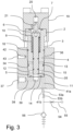
- the inlet-outlet valve body 2 see Fig. 3 , consist of an upper valve body part 3, a middle valve body part 4, and a lower valve body part 5 with the outer cross-sectional area of the lower valve body part 5 being less than the outer cross-sectional area of the middle valve body part 4, and with the outer cross-sectional area of the middle valve body part 4 being less than the outer cross-sectional area of the upper valve body part 3.
- the valve body 2 surrounds a through-going inlet-outlet valve piston chamber 6 forming an upper opening 7 in the upper valve body part 3 and a valve inlet opening 8 at the bottom in the lower valve body part 5.
- the inlet-outlet valve piston chamber 6 holds an inlet-outlet valve spring 9 within an upper part of the chamber and an inlet-outlet valve piston 10 with a piston valve seat 11 formed at the lower end of the inlet-outlet valve piston 10.
- the inlet-outlet valve body 2 holds one or more lower valve outlet channels 12, see Fig. 3 , 4 and 5 , providing a fluid connection from outer wall parts of the lower valve body part 5 to the inlet-outlet valve piston chamber 6, whereby the inlet-outlet valve is open when the valve seat 11 is lifted above the outlet channels 12 by the force of the inlet-outlet valve spring 9, thereby providing a fluid connection from the valve inlet opening 8 to the outer wall parts of the valve body 2.
- the inlet-outlet valve is closed when the valve seat 11 is pressed below the outlet channels 12 by a pressure exercised on the inlet-outlet valve piston 10.
- the valve body 2 also holds one or more test channels 13. See Fig. 3 and 4 , providing a fluid connection from the inlet-outlet valve piston chamber 6 to outer wall parts of the middle part 4 of the valve body above 2 the lower valve outlet channels 12.
- a lower valve body sealing ring 14, see Figs. 3 , 4 and 5 surrounds the valve inlet opening 8 at the bottom of the inlet-outlet valve body 2
- a middle valve body sealing ring 15 surrounds the middle part 4 of the valve body below the test channels 13
- an upper valve body sealing ring 16 surrounds an upper part 3 of the valve body above the test channels 13.
- Lower 17 and upper 18 piston sealing rings are provided for sealing the inlet-outlet valve piston 10 within the inlet-outlet valve piston chamber 6, see Fig.
- the top cover 19 holds a cover piston chamber 20 with a cover piston 21, and a cover fluid channel 22a providing a fluid connection from a side part of the top cover 19 to an upper part of the cover piston chamber 6.
- a lower oil supply part 23 with a valve oil supply chamber 24 in fluid connection with a lower valve oil supply channel 25b and an upper valve oil supply channel 25a.
- the upper valve oil supply channel provides a fluid connection from the supply chamber 24 to a side part of the top cover 19.
- a lower oil drainage part 26 with a valve oil drainage chamber 27 in fluid connection with a valve oil drainage channel 28.
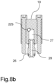
- the top cover also holds a cover fluid release channel 22b, see Fig. 8a and 8b , providing a fluid connection from a side part of the top cover 19 to the valve oil drainage chamber 27.
- the top cover 19 is connected to the inlet-outlet valve body 2, see Fig. 2 , with the cover piston 21 reaching out from the cover piston chamber 20 to a top end part of the inlet-outlet valve piston 10 whereby a downwards pressure can be provided by the cover piston 21 to the inlet-outlet valve piston 10 for closing the inlet-outlet valve.
- the lower oil supply part 23 and the lower oil drainage part 26 extend on opposite sides of the upper valve body part 3.
- the fluid inlet 29 opens and the hydraulic oil will flow through the inlet 29 and through internal channels (not shown in the figures) of the electro-magnetic directional valve 31 and flows out from an electro-magnetic valve fluid outlet 30a to the cover fluid channel 22a and to the cover piston chamber 20, see Fig. 2 , where the hydraulic oil press down the cover piston 21, which again will press down the inlet-outlet valve piston 10 and the piston valve seat 11, while at the same time compressing the inlet-outlet valve spring 9.
- An electric on/off contact 32 is connected to the electro-magnetic valve 31 for connecting and disconnecting supply of 24 Volt DC to the electro-magnetic valve 31, see Fig. 2 .
- the test unit 33 comprises a test chamber 34 with an opening for receiving the inlet-outlet valve body 2.
- the test chamber 34 is divided in an upper part configured to match the outer cross-sectional area of the upper valve body part 3 and a lower part configured to match the outer cross-sectional area of the middle valve body part 4, where the lower test chamber part has a test gas outlet 40 at the bottom, where the test gas outlet 40 is an upper opening of a test gas chamber 39 provided below the test chamber 34.
- the test gas outlet 40 is configured to match the bottom valve inlet 8 of the inlet-outlet valve piston chamber 6.
- the test unit 33 holds a test gas inlet port 37 in fluid connection with the test gas chamber 39 via a bottom test gas channel 38 , and a control oil inlet port 44 in fluid connection with a control oil supply chamber 46 via a control oil supply channel 45, which is configured for receiving the lower oil supply part 23 of the top cover 19.
- the test unit 33 also holds an oil drainage port 47 in fluid connection with a control oil drainage chamber 49 via a control oil drainage channel 40, where the control oil drainage chamber 49 is configured for receiving the lower oil drainage part 26 of the top cover 19.
- the test unit 33 further holds an upper gas leak port 43 in fluid connection with the upper part of the test chamber 34 via an upper gas leak channel 42, and a lower gas leak channel 41a providing a fluid connection from a side-bottom part of the lower test chamber part to a lower gas leak port 41b of the test unit 33.
- the valve unit 1 is connected to the test unit 33 with the inlet-outlet valve inserted into the test chamber 34 of the test unit 33, whereby the valve body 2 reaches into the test chamber 34 with the bottom valve inlet opening 8 facing the bottom test gas outlet 40 of the test chamber 34.
- a fluid connection is provided between the test gas inlet port 37 via the test gas chamber 39 to the valve inlet 8 at the bottom of the inlet-outlet valve piston chamber 6.
- a lower fluid space 35 see Figs. 3 and 4 , is provided between the outer walls of the lower valve body part 5 and the lower part of the test chamber 34 thereby providing a fluid connection from the lower valve outlet channels 12 via the lower gas leak channel 41a to the lower gas leak port 41b.
- the lower test gas outlet 40 and the valve inlet opening 8 are fluidly sealed from the lower fluid space 35 by the lower valve body sealing ring 14.
- the upper valve body part 3 reaches partly into the upper part of the test chamber 34, whereby an upper fluid space 36, see Fig. 3 and 4 , is provided between the outer walls of the middle valve body part 4 and the upper part of the test chamber 34 and a fluid connection is provided from the test channels 13 to the upper gas leak port 43.
- the lower fluid space 35 is sealed by the lower 14 and middle 15 valve body sealing rings, and the upper fluid space 36 is sealed by the middle 15 and upper 16 valve body sealing rings.
- the lower oil supply part 23 is received by the control oil supply chamber 46 of the test unit 33, see Figs. 1 and 2 , with a fluid connection being provided from the control oil inlet port 44, via the control oil supply chamber 46 and the lower valve oil supply channel 25b to the valve oil supply chamber 24.
- the lower oil drainage part 26 is received by the control oil drainage chamber 49 of the test unit 33 with a fluid connection being provided from the control oil drainage port 47, via the control oil drainage chamber 49 and the valve oil drainage channel 28 to the valve oil drainage chamber 27.
- a stop valve 53b is fluidly connected to the lower gas leak port 41b via a leakage gas pipe 53a for closing and opening for gas being outlet from the lower gas leak port 41b.
- the stop valve 53b has one outlet connected to one end of a lower flexible hose 55 via a leakage gas outlet 54, which leakage gas outlet 54 has a relatively small diameter, such as 0,3mm, with the other end of the lower flexible hose 55 connected to a separate container 51 with liquid, whereby any test gas reaching through the lower gas leak port 41b when the stop valve 53b is open is observed as bubbles in the liquid of the container 51.
- a non-return valve 56 is connected to another output of the stop valve 53b.
- the non-return 56 valve will open an allow the test gas to be leaked into a silencer 57, which is connected to the non-return valve 56.
- Another upper flexible hose 52 is connected to the upper gas leak port 43 and leading into the liquid in the container 51.
- the liquid in the container 51 is water
- the test gas is Nitrogen
- Fig. 9 is a diagram of a test system with lines for supply of control oil and test gas for testing the valve unit of Fig. 1 according to an example embodiment.
- Fig. 9 is a diagram of a test system 100 with lines for supply of control oil 100d and test gas 100c for performing a leakage test of the inlet-outlet valve of the valve unit 1 of Figs. 1 and 6 , for which test the valve unit 1 is inserted into the test unit 33.
- a stop valve 53b is fluidly connected to the lower gas leak port 41b via a leakage gas pipe 53a.
- the stop valve 53b has one outlet connected to one end of a lower flexible hose 55 via a leakage gas outlet 54, which leakage gas outlet 54 has a relatively small diameter, such as 0,3mm, with the other end of the lower flexible hose 55 connected to a separate container 51 with liquid, whereby any test gas reaching through the lower gas leak port 41b when the stop valve 53b is open is observed as bubbles in the liquid of the container 51.
- a non-return valve 56 is connected to another output of the stop valve 53b.
- the non-return 56 valve will open an allow the test gas to be leaked into a silencer 57, which is connected to the non-return valve 56.
- Another upper flexible hose 52 is connected to the upper gas leak port 43 and leading into the liquid in the container 51.
- An oil drainage pipe 50 is connected to the control oil drainage port 47 of the test unit 33, in order receive any oil being outlet via the control oil drainage port 47.
- the voltage supply to the electro-magnetic valve 31 of the valve unit 1 can be turned on and off by the on/off contact 32.
- the test system 100 illustrated in Fig. 9 comprises an air inlet 100b for inlet of air at a pressure in the range of 7 - 10 bar, which pressurized air is used as input to three pressure control valves, a control oil pressure control valve 108, a sealing oil pressure control valve 115, and a fuel oil pressure control valve 120.
- a gas inlet 100a is provided for inlet of a test gas in the form of Nitrogen at a pressure in the range of 200-300 bar.
- the pressurized Nitrogen is supplied to a gas stop valve 110, with a gas pressure control valve 112 being provided for controlling the pressure of the gas being output from the gas stop valve 110 to the gas outlet 100c.
- a gas pressure relief valve 111 is connected to the gas line connection between the gas stop valve 110 and the gas outlet 100c and the gas pressure can be read from a gas pressure gauge 113.
- a test fluid in the form of a hydraulic oil which may be a mineral hydraulic oil with a viscosity of 10 centistokes (cSt)
- oil thank 109 holding the hydraulic oil is provided.
- An outlet of the oil tank 109 is connected to three air driven pumps, a control oil air driven pump 107 being controlled by the control oil pressure control valve 108, a sealing oil air driven pump 118 being controlled by the sealing oil pressure control valve 115, and a fuel oil air driven pump 123 being controlled by the fuel oil pressure control valve 120.
- the oil pressure from the control oil air driven pump 107 can be read from a control oil pressure gauge 106, and the oil pressure from the control oil air driven pump 107 can be released by a control oil pressure relief valve 102, in which case released hydraulic oil will flow back to the oil tank 109.
- a hydraulic accumulator 105 is provided, which accumulator 105 may be charged by opening or closing a control oil stop valve 103.
- a control oil pressure safety valve 104 is provided as a safety valve adjusted to a maximum working pressure of 240 bar for the hydraulic accumulator 105 in order to protect the accumulator 105 against too high pressure.
- the hydraulic accumulator 105 is a membrane type of accumulator. It has a chamber which is divided by a rubber membrane. On one side of the membrane is Nitrogen at a pressure of 120 bar, on the other side of the membrane is hydraulic oil supplied from the control oil air driven pump 107. While the pressure of hydraulic oil is 0 bar, then the whole volume of accumulator is filled with Nitrogen.
- the Nitrogen will start compress, as the hydraulic oil will start filling the volume of hydraulic accumulator.
- the purpose of the accumulator 105 in the test system 100 is to accumulate hydraulic oil inside with a pressure. While releasing oil pressure it is possible to get a high peak oil flow output from the accumulator 105.
- a control oil directional valve 101 is provided for opening or closing of control oil supply from the control oil air drive pump 107 and the hydraulic accumulator 105 to a control oil outlet 100d. While testing the inlet-outlet valve of valve unit 1, it may be necessary to provide control oil with a high flow in a short time through the control oil directional valve 101 to the control oil outlet 100d. The pump 107 is not able to provide the required control oil flow alone, wherefore the high peak control oil delivery from the hydraulic accumulator 105 may be needed.
- Sealing oil may be provided from the sealing oil air driven pump 118 to a sealing oil outlet 100e, and the oil pressure from the sealing oil air driven pump 118 can be read from a sealing oil pressure gauge 117, while the oil pressure from the sealing oil air driven pump 118 can be released by a sealing oil pressure relief valve 114, in which case released hydraulic oil will flow back to the oil tank 109.
- a sealing oil pressure safety valve 116 is provided for protection of the sealing oil pressure gauge 117. The sealing oil pressure safety valve 116 is adjusted to a maximum working pressure of 150 bar at the output side of the sealing oil air driven pump 118. If the sealing oil pressure exceeds the 150 bar, the sealing oil safety valve 116 will open and hydraulic oil will flow back to the oil tank 109.
- Fuel oil may be provided from the fuel oil air driven pump 123 to a fuel oil outlet 100f, and the oil pressure from the fuel oil air driven pump 123 can be read from a fuel oil pressure gauge 122, while the oil pressure from the fuel oil air driven pump 123 can be released by a sealing oil pressure relief valve 119, in which case released hydraulic oil will flow back to the oil tank 109.
- a fuel oil pressure safety valve 121 is provided for protection of the fuel oil pressure gauge 122. The fuel oil pressure safety valve 121 is adjusted to a maximum working pressure of 150 bar at the output side of the fuel oil air driven pump 123. If the fuel oil pressure exceeds the 150 bar, the fuel oil safety valve 121 will open and hydraulic oil will flow back to the oil tank 109.
- Test gas in the form of Nitrogen is supplied from the system 100 via the gas outlet 100c to the test gas inlet port 37 of the test unit 33 by use of a Nitrogen hose, and control oil in the form of hydraulic oil is supplied from the system 100 via the control oil outlet 100d to the control oil inlet port 44 of the test unit 33 by use of a control oil high pressure hose.
Landscapes
- Engineering & Computer Science (AREA)
- General Engineering & Computer Science (AREA)
- Physics & Mathematics (AREA)
- General Physics & Mathematics (AREA)
- Mechanical Engineering (AREA)
- Chemical & Material Sciences (AREA)
- Combustion & Propulsion (AREA)
- Testing Of Devices, Machine Parts, Or Other Structures Thereof (AREA)
- Examining Or Testing Airtightness (AREA)
- Safety Valves (AREA)
- Details Of Valves (AREA)
Applications Claiming Priority (3)
| Application Number | Priority Date | Filing Date | Title |
|---|---|---|---|
| DKPA201970568A DK180460B1 (en) | 2019-09-13 | 2019-09-13 | Method for testing an inlet-outlet valve |
| PCT/DK2020/050246 WO2021047744A1 (en) | 2019-09-13 | 2020-09-09 | Test unit and method for testing an inlet-outlet valve |
| EP20862339.7A EP4028741B1 (de) | 2019-09-13 | 2020-09-09 | Prüfeinheit und verfahren zum prüfen eines einlass-auslass-ventils |
Related Parent Applications (2)
| Application Number | Title | Priority Date | Filing Date |
|---|---|---|---|
| EP20862339.7A Division EP4028741B1 (de) | 2019-09-13 | 2020-09-09 | Prüfeinheit und verfahren zum prüfen eines einlass-auslass-ventils |
| EP20862339.7A Division-Into EP4028741B1 (de) | 2019-09-13 | 2020-09-09 | Prüfeinheit und verfahren zum prüfen eines einlass-auslass-ventils |
Publications (3)
| Publication Number | Publication Date |
|---|---|
| EP4400752A2 true EP4400752A2 (de) | 2024-07-17 |
| EP4400752A3 EP4400752A3 (de) | 2024-10-23 |
| EP4400752B1 EP4400752B1 (de) | 2025-11-12 |
Family
ID=74865673
Family Applications (2)
| Application Number | Title | Priority Date | Filing Date |
|---|---|---|---|
| EP20862339.7A Active EP4028741B1 (de) | 2019-09-13 | 2020-09-09 | Prüfeinheit und verfahren zum prüfen eines einlass-auslass-ventils |
| EP24170772.8A Active EP4400752B1 (de) | 2019-09-13 | 2020-09-09 | Verfahren zum testen eines ein-/auslassventils |
Family Applications Before (1)
| Application Number | Title | Priority Date | Filing Date |
|---|---|---|---|
| EP20862339.7A Active EP4028741B1 (de) | 2019-09-13 | 2020-09-09 | Prüfeinheit und verfahren zum prüfen eines einlass-auslass-ventils |
Country Status (6)
| Country | Link |
|---|---|
| EP (2) | EP4028741B1 (de) |
| JP (1) | JP7508547B2 (de) |
| KR (1) | KR102927959B1 (de) |
| CN (1) | CN114364961B (de) |
| DK (4) | DK180460B1 (de) |
| WO (1) | WO2021047744A1 (de) |
Families Citing this family (4)
| Publication number | Priority date | Publication date | Assignee | Title |
|---|---|---|---|---|
| DK180473B1 (en) * | 2019-09-06 | 2021-05-07 | Iop Marine As | Method for testing a valve body of an injector valve and method for testing an injector valve |
| CN114984401B (zh) * | 2022-05-30 | 2026-02-17 | 深圳市安保医疗科技股份有限公司 | 一种气路电磁控制阀组件以及呼吸机 |
| CN115200791B (zh) * | 2022-07-20 | 2023-03-14 | 安徽众汇制冷有限公司 | 一种异型管消音器气密性检测设备 |
| CN116242548A (zh) * | 2023-03-24 | 2023-06-09 | 上海乐春重工机电设备有限公司 | 一种喷气阀件密封测试装置和测试方法 |
Citations (2)
| Publication number | Priority date | Publication date | Assignee | Title |
|---|---|---|---|---|
| WO2013124035A1 (en) | 2012-02-22 | 2013-08-29 | Iop Marine A/S | Method of testing a gas shut-down valve and a system for exercising the method |
| US20140318221A1 (en) | 2011-11-09 | 2014-10-30 | Iop Marine A/S | Method of Testing a Gas Injector Valve and a System for Exercising the Method |
Family Cites Families (6)
| Publication number | Priority date | Publication date | Assignee | Title |
|---|---|---|---|---|
| US4278130A (en) * | 1979-10-17 | 1981-07-14 | Halliburton Company | Access valve for drill stem testing |
| US20130133405A1 (en) * | 2011-11-25 | 2013-05-30 | Tareq Nasser Al-Buaijan | Shut-off valve testing system |
| GB2566418A (en) | 2016-06-30 | 2019-03-13 | A Bowen Billy JR | Test-port activated tubing hanger control valve |
| US10041610B2 (en) * | 2016-10-20 | 2018-08-07 | Fisher Controls International Llc | Methods and apparatus of stabilizing a valve positioner when testing a solenoid valve |
| KR101722966B1 (ko) * | 2016-11-18 | 2017-04-05 | (주)한미유압기계 | 가스분사밸브 검사장치 |
| CN207649895U (zh) | 2017-12-28 | 2018-07-24 | 上海沪东造船油嘴油泵有限公司 | 窗口阀性能测试工具 |
-
2019
- 2019-09-13 DK DKPA201970568A patent/DK180460B1/en active IP Right Grant
-
2020
- 2020-01-17 DK DKPA202070037A patent/DK180474B1/en active IP Right Grant
- 2020-09-09 WO PCT/DK2020/050246 patent/WO2021047744A1/en not_active Ceased
- 2020-09-09 KR KR1020227011385A patent/KR102927959B1/ko active Active
- 2020-09-09 DK DK24170772.8T patent/DK4400752T3/da active
- 2020-09-09 JP JP2022514635A patent/JP7508547B2/ja active Active
- 2020-09-09 DK DK20862339.7T patent/DK4028741T3/da active
- 2020-09-09 EP EP20862339.7A patent/EP4028741B1/de active Active
- 2020-09-09 CN CN202080063988.XA patent/CN114364961B/zh active Active
- 2020-09-09 EP EP24170772.8A patent/EP4400752B1/de active Active
Patent Citations (3)
| Publication number | Priority date | Publication date | Assignee | Title |
|---|---|---|---|---|
| US20140318221A1 (en) | 2011-11-09 | 2014-10-30 | Iop Marine A/S | Method of Testing a Gas Injector Valve and a System for Exercising the Method |
| WO2013124035A1 (en) | 2012-02-22 | 2013-08-29 | Iop Marine A/S | Method of testing a gas shut-down valve and a system for exercising the method |
| US20150007639A1 (en) | 2012-02-22 | 2015-01-08 | Iop Marine A/S | Method of testing a gas shut-down valve and a system for exercising the method |
Also Published As
| Publication number | Publication date |
|---|---|
| JP2022547283A (ja) | 2022-11-11 |
| DK4028741T3 (en) | 2024-07-22 |
| KR20220061168A (ko) | 2022-05-12 |
| CN114364961B (zh) | 2025-10-28 |
| DK4400752T3 (da) | 2025-12-22 |
| EP4400752B1 (de) | 2025-11-12 |
| EP4028741A1 (de) | 2022-07-20 |
| CN114364961A (zh) | 2022-04-15 |
| DK180474B1 (en) | 2021-05-07 |
| WO2021047744A1 (en) | 2021-03-18 |
| EP4028741A4 (de) | 2023-05-10 |
| DK202070037A1 (en) | 2021-05-07 |
| EP4028741B1 (de) | 2024-06-12 |
| JP7508547B2 (ja) | 2024-07-01 |
| DK201970568A1 (en) | 2021-05-06 |
| EP4400752A3 (de) | 2024-10-23 |
| DK180460B1 (en) | 2021-05-06 |
| KR102927959B1 (ko) | 2026-02-13 |
Similar Documents
| Publication | Publication Date | Title |
|---|---|---|
| EP4028741B1 (de) | Prüfeinheit und verfahren zum prüfen eines einlass-auslass-ventils | |
| EP2776703B1 (de) | Verfahren zum testen eines gaseinspritzventil und system zur durchführung des verfahrens | |
| US9599530B2 (en) | Method of testing a gas shut-down valve and a system for exercising the method | |
| JP6807861B2 (ja) | 液化ガス用のインジェクタ弁をテストする方法 | |
| EP4025775B1 (de) | Verfahren zum prüfen eines ventilkörpers eines einspritzventils und verfahren zum prüfen eines einspritzventils | |
| WO2023088755A1 (en) | Method for testing an injector valve | |
| DK180461B1 (en) | Method for testing a valve body of an injector valve and method for testing an injector valve | |
| DK182314B1 (en) | System and method for testing a suction valve | |
| WO2026061595A1 (en) | A method of testing a valve body of an injector valve | |
| DK202530126A1 (en) | Method for testing an opening pressure of a nozzle valve of a safety suction valve |
Legal Events
| Date | Code | Title | Description |
|---|---|---|---|
| PUAI | Public reference made under article 153(3) epc to a published international application that has entered the european phase |
Free format text: ORIGINAL CODE: 0009012 |
|
| STAA | Information on the status of an ep patent application or granted ep patent |
Free format text: STATUS: THE APPLICATION HAS BEEN PUBLISHED |
|
| AC | Divisional application: reference to earlier application |
Ref document number: 4028741 Country of ref document: EP Kind code of ref document: P |
|
| AK | Designated contracting states |
Kind code of ref document: A2 Designated state(s): AL AT BE BG CH CY CZ DE DK EE ES FI FR GB GR HR HU IE IS IT LI LT LU LV MC MK MT NL NO PL PT RO RS SE SI SK SM TR |
|
| REG | Reference to a national code |
Ref country code: DE Free format text: PREVIOUS MAIN CLASS: F16K0037000000 Ref country code: DE Ref legal event code: R079 Ref document number: 602020062315 Country of ref document: DE Free format text: PREVIOUS MAIN CLASS: F16K0037000000 Ipc: G01M0003080000 |
|
| PUAL | Search report despatched |
Free format text: ORIGINAL CODE: 0009013 |
|
| AK | Designated contracting states |
Kind code of ref document: A3 Designated state(s): AL AT BE BG CH CY CZ DE DK EE ES FI FR GB GR HR HU IE IS IT LI LT LU LV MC MK MT NL NO PL PT RO RS SE SI SK SM TR |
|
| RIC1 | Information provided on ipc code assigned before grant |
Ipc: G01M 3/28 20060101ALI20240913BHEP Ipc: F16K 37/00 20060101ALI20240913BHEP Ipc: G01M 3/08 20060101AFI20240913BHEP |
|
| STAA | Information on the status of an ep patent application or granted ep patent |
Free format text: STATUS: REQUEST FOR EXAMINATION WAS MADE |
|
| 17P | Request for examination filed |
Effective date: 20250423 |
|
| GRAP | Despatch of communication of intention to grant a patent |
Free format text: ORIGINAL CODE: EPIDOSNIGR1 |
|
| STAA | Information on the status of an ep patent application or granted ep patent |
Free format text: STATUS: GRANT OF PATENT IS INTENDED |
|
| RIC1 | Information provided on ipc code assigned before grant |
Ipc: G01M 3/08 20060101AFI20250630BHEP Ipc: F16K 37/00 20060101ALI20250630BHEP Ipc: G01M 3/28 20060101ALI20250630BHEP |
|
| INTG | Intention to grant announced |
Effective date: 20250711 |
|
| GRAS | Grant fee paid |
Free format text: ORIGINAL CODE: EPIDOSNIGR3 |
|
| GRAA | (expected) grant |
Free format text: ORIGINAL CODE: 0009210 |
|
| STAA | Information on the status of an ep patent application or granted ep patent |
Free format text: STATUS: THE PATENT HAS BEEN GRANTED |
|
| AC | Divisional application: reference to earlier application |
Ref document number: 4028741 Country of ref document: EP Kind code of ref document: P |
|
| AK | Designated contracting states |
Kind code of ref document: B1 Designated state(s): AL AT BE BG CH CY CZ DE DK EE ES FI FR GB GR HR HU IE IS IT LI LT LU LV MC MK MT NL NO PL PT RO RS SE SI SK SM TR |
|
| REG | Reference to a national code |
Ref country code: CH Ref legal event code: F10 Free format text: ST27 STATUS EVENT CODE: U-0-0-F10-F00 (AS PROVIDED BY THE NATIONAL OFFICE) Effective date: 20251112 Ref country code: GB Ref legal event code: FG4D |
|
| REG | Reference to a national code |
Ref country code: CH Ref legal event code: R17 Free format text: ST27 STATUS EVENT CODE: U-0-0-R10-R17 (AS PROVIDED BY THE NATIONAL OFFICE) Effective date: 20251119 |
|
| REG | Reference to a national code |
Ref country code: IE Ref legal event code: FG4D |
|
| REG | Reference to a national code |
Ref country code: DE Ref legal event code: R096 Ref document number: 602020062315 Country of ref document: DE |
|
| REG | Reference to a national code |
Ref country code: DK Ref legal event code: T3 Effective date: 20251219 |
|
| REG | Reference to a national code |
Ref country code: NL Ref legal event code: MP Effective date: 20251112 |
|
| PG25 | Lapsed in a contracting state [announced via postgrant information from national office to epo] |
Ref country code: ES Free format text: LAPSE BECAUSE OF FAILURE TO SUBMIT A TRANSLATION OF THE DESCRIPTION OR TO PAY THE FEE WITHIN THE PRESCRIBED TIME-LIMIT Effective date: 20251112 |
|
| REG | Reference to a national code |
Ref country code: LT Ref legal event code: MG9D |
|
| PG25 | Lapsed in a contracting state [announced via postgrant information from national office to epo] |
Ref country code: NO Free format text: LAPSE BECAUSE OF FAILURE TO SUBMIT A TRANSLATION OF THE DESCRIPTION OR TO PAY THE FEE WITHIN THE PRESCRIBED TIME-LIMIT Effective date: 20260212 |
|
| PG25 | Lapsed in a contracting state [announced via postgrant information from national office to epo] |
Ref country code: FI Free format text: LAPSE BECAUSE OF FAILURE TO SUBMIT A TRANSLATION OF THE DESCRIPTION OR TO PAY THE FEE WITHIN THE PRESCRIBED TIME-LIMIT Effective date: 20251112 Ref country code: HR Free format text: LAPSE BECAUSE OF FAILURE TO SUBMIT A TRANSLATION OF THE DESCRIPTION OR TO PAY THE FEE WITHIN THE PRESCRIBED TIME-LIMIT Effective date: 20251112 Ref country code: AT Free format text: LAPSE BECAUSE OF FAILURE TO SUBMIT A TRANSLATION OF THE DESCRIPTION OR TO PAY THE FEE WITHIN THE PRESCRIBED TIME-LIMIT Effective date: 20251112 |
|
| REG | Reference to a national code |
Ref country code: AT Ref legal event code: MK05 Ref document number: 1857091 Country of ref document: AT Kind code of ref document: T Effective date: 20251112 |
|
| PG25 | Lapsed in a contracting state [announced via postgrant information from national office to epo] |
Ref country code: NL Free format text: LAPSE BECAUSE OF FAILURE TO SUBMIT A TRANSLATION OF THE DESCRIPTION OR TO PAY THE FEE WITHIN THE PRESCRIBED TIME-LIMIT Effective date: 20251112 |
|
| PG25 | Lapsed in a contracting state [announced via postgrant information from national office to epo] |
Ref country code: RS Free format text: LAPSE BECAUSE OF FAILURE TO SUBMIT A TRANSLATION OF THE DESCRIPTION OR TO PAY THE FEE WITHIN THE PRESCRIBED TIME-LIMIT Effective date: 20260212 |
|
| PG25 | Lapsed in a contracting state [announced via postgrant information from national office to epo] |
Ref country code: IS Free format text: LAPSE BECAUSE OF FAILURE TO SUBMIT A TRANSLATION OF THE DESCRIPTION OR TO PAY THE FEE WITHIN THE PRESCRIBED TIME-LIMIT Effective date: 20260312 |
|
| PG25 | Lapsed in a contracting state [announced via postgrant information from national office to epo] |
Ref country code: PT Free format text: LAPSE BECAUSE OF FAILURE TO SUBMIT A TRANSLATION OF THE DESCRIPTION OR TO PAY THE FEE WITHIN THE PRESCRIBED TIME-LIMIT Effective date: 20260312 |
|
| PG25 | Lapsed in a contracting state [announced via postgrant information from national office to epo] |
Ref country code: PL Free format text: LAPSE BECAUSE OF FAILURE TO SUBMIT A TRANSLATION OF THE DESCRIPTION OR TO PAY THE FEE WITHIN THE PRESCRIBED TIME-LIMIT Effective date: 20251112 |
|
| PG25 | Lapsed in a contracting state [announced via postgrant information from national office to epo] |
Ref country code: LV Free format text: LAPSE BECAUSE OF FAILURE TO SUBMIT A TRANSLATION OF THE DESCRIPTION OR TO PAY THE FEE WITHIN THE PRESCRIBED TIME-LIMIT Effective date: 20251112 |