EP4400729A2 - Vakuumerzeuger mit mehreren saugdüsen, befestigungsmittel-vakuumerzeuger mit mehreren saugdüsen und vakuumerzeugerpumpe - Google Patents
Vakuumerzeuger mit mehreren saugdüsen, befestigungsmittel-vakuumerzeuger mit mehreren saugdüsen und vakuumerzeugerpumpe Download PDFInfo
- Publication number
- EP4400729A2 EP4400729A2 EP23214906.2A EP23214906A EP4400729A2 EP 4400729 A2 EP4400729 A2 EP 4400729A2 EP 23214906 A EP23214906 A EP 23214906A EP 4400729 A2 EP4400729 A2 EP 4400729A2
- Authority
- EP
- European Patent Office
- Prior art keywords
- nozzle
- vacuum
- vacuum generator
- ejector
- calculation
- Prior art date
- Legal status (The legal status is an assumption and is not a legal conclusion. Google has not performed a legal analysis and makes no representation as to the accuracy of the status listed.)
- Granted
Links
Images


Classifications
-
- F—MECHANICAL ENGINEERING; LIGHTING; HEATING; WEAPONS; BLASTING
- F04—POSITIVE - DISPLACEMENT MACHINES FOR LIQUIDS; PUMPS FOR LIQUIDS OR ELASTIC FLUIDS
- F04F—PUMPING OF FLUID BY DIRECT CONTACT OF ANOTHER FLUID OR BY USING INERTIA OF FLUID TO BE PUMPED; SIPHONS
- F04F5/00—Jet pumps, i.e. devices in which flow is induced by pressure drop caused by velocity of another fluid flow
- F04F5/14—Jet pumps, i.e. devices in which flow is induced by pressure drop caused by velocity of another fluid flow the inducing fluid being elastic fluid
- F04F5/16—Jet pumps, i.e. devices in which flow is induced by pressure drop caused by velocity of another fluid flow the inducing fluid being elastic fluid displacing elastic fluids
- F04F5/20—Jet pumps, i.e. devices in which flow is induced by pressure drop caused by velocity of another fluid flow the inducing fluid being elastic fluid displacing elastic fluids for evacuating
- F04F5/22—Jet pumps, i.e. devices in which flow is induced by pressure drop caused by velocity of another fluid flow the inducing fluid being elastic fluid displacing elastic fluids for evacuating of multi-stage type
-
- F—MECHANICAL ENGINEERING; LIGHTING; HEATING; WEAPONS; BLASTING
- F04—POSITIVE - DISPLACEMENT MACHINES FOR LIQUIDS; PUMPS FOR LIQUIDS OR ELASTIC FLUIDS
- F04F—PUMPING OF FLUID BY DIRECT CONTACT OF ANOTHER FLUID OR BY USING INERTIA OF FLUID TO BE PUMPED; SIPHONS
- F04F5/00—Jet pumps, i.e. devices in which flow is induced by pressure drop caused by velocity of another fluid flow
- F04F5/14—Jet pumps, i.e. devices in which flow is induced by pressure drop caused by velocity of another fluid flow the inducing fluid being elastic fluid
- F04F5/16—Jet pumps, i.e. devices in which flow is induced by pressure drop caused by velocity of another fluid flow the inducing fluid being elastic fluid displacing elastic fluids
- F04F5/20—Jet pumps, i.e. devices in which flow is induced by pressure drop caused by velocity of another fluid flow the inducing fluid being elastic fluid displacing elastic fluids for evacuating
-
- F—MECHANICAL ENGINEERING; LIGHTING; HEATING; WEAPONS; BLASTING
- F04—POSITIVE - DISPLACEMENT MACHINES FOR LIQUIDS; PUMPS FOR LIQUIDS OR ELASTIC FLUIDS
- F04F—PUMPING OF FLUID BY DIRECT CONTACT OF ANOTHER FLUID OR BY USING INERTIA OF FLUID TO BE PUMPED; SIPHONS
- F04F5/00—Jet pumps, i.e. devices in which flow is induced by pressure drop caused by velocity of another fluid flow
- F04F5/44—Component parts, details, or accessories not provided for in, or of interest apart from, groups F04F5/02 - F04F5/42
- F04F5/46—Arrangements of nozzles
- F04F5/466—Arrangements of nozzles with a plurality of nozzles arranged in parallel
-
- F—MECHANICAL ENGINEERING; LIGHTING; HEATING; WEAPONS; BLASTING
- F04—POSITIVE - DISPLACEMENT MACHINES FOR LIQUIDS; PUMPS FOR LIQUIDS OR ELASTIC FLUIDS
- F04F—PUMPING OF FLUID BY DIRECT CONTACT OF ANOTHER FLUID OR BY USING INERTIA OF FLUID TO BE PUMPED; SIPHONS
- F04F5/00—Jet pumps, i.e. devices in which flow is induced by pressure drop caused by velocity of another fluid flow
- F04F5/44—Component parts, details, or accessories not provided for in, or of interest apart from, groups F04F5/02 - F04F5/42
- F04F5/46—Arrangements of nozzles
- F04F5/467—Arrangements of nozzles with a plurality of nozzles arranged in series
-
- F—MECHANICAL ENGINEERING; LIGHTING; HEATING; WEAPONS; BLASTING
- F04—POSITIVE - DISPLACEMENT MACHINES FOR LIQUIDS; PUMPS FOR LIQUIDS OR ELASTIC FLUIDS
- F04F—PUMPING OF FLUID BY DIRECT CONTACT OF ANOTHER FLUID OR BY USING INERTIA OF FLUID TO BE PUMPED; SIPHONS
- F04F5/00—Jet pumps, i.e. devices in which flow is induced by pressure drop caused by velocity of another fluid flow
- F04F5/54—Installations characterised by use of jet pumps, e.g. combinations of two or more jet pumps of different type
Definitions
- the present invention belongs to the field of industrial vacuum pumps, more specifically to vacuum pumps that use ejectors.
- the main application of this vacuum pump is cargo transportation.
- Vacuum pumps with ejectors or multi-ejectors use compressed air, inert gases or steam which, when subjected to convergent-divergent tubes, result in a drop in pressure.
- Multi-ejector vacuum pumps use the Venturi principle to generate a vacuum.
- Each nozzle comprises a convergent-divergent nozzle, in order to accelerate the fluid, decreasing its pressure, producing the vacuum for industrial applications.
- US10400796B2 fails to describe nozzles. US10400796B2 reveals that any nozzle can be used as long as it has an inlet, an outlet and a connection to the outside air along its length. This prior art also presents a fixation means completely different from that proposed by the present invention.
- Documents PI and C1 0501916-8 differ from the present invention due to the construction of the vacuum chambers which, in the present invention, present ease manufacturing, in addition to the fact that no information related to the diameters, lengths or shape of the nozzles was revealed.
- the present invention aims to present a considerably higher efficiency than the vacuum pumps on the market, in particular, the multi-ejector vacuum pumps.
- the present invention discloses a multi-ejector vacuum generator for a vacuum generating pump comprising at least three stages and at least four nozzles, each stage comprising a vacuum chamber and at least two diaphragms configured to act as one-way valves; each nozzle is configured to act as a receiver at its proximal end and an ejector at its distal end; wherein, the first nozzle is convergent-parallel-divergent, the second nozzle is parallel, the third nozzle is parallel-divergent and the fourth nozzle is parallel-divergent; wherein, the distal end of the first nozzle is connected to the first stage vacuum chamber in its proximal portion; the proximal end of the second nozzle is connected to the first stage vacuum chamber in its distal portion; the distal end of the second nozzle is connected to the second stage vacuum chamber in its proximal portion; the proximal end of the third nozzle is connected to the second stage vacuum chamber in its distal portion; the distal end of the third
- the present multi-ejector vacuum generator for vacuum generator pumps reveals that the nozzles are positioned internally to the stages, configured longitudinally, and the diaphragms are positioned on the external surfaces of the stages vacuum chamber, orthogonally to the nozzles.
- Said multi-ejector vacuum generator for vacuum generator pumps provides a feeding sleeve configured to connect the compressed air inlet with the first nozzle.
- the present multi-ejector vacuum generator for vacuum generator pump establishes that between the compressed air inlet and the first nozzle there is a manifold reservoir or air passage control solenoid valves.
- the multi-ejector vacuum generator for vacuum generator pump disclosed by the present invention establishes that the first nozzle has in its parallel portion, a diameter preferably between 3 and 60 mm, more preferably between 4 and 56 mm, even more preferably between 4.24 mm and 54.38 mm, and in its divergent portion, angle of divergence preferably between 7 and 9 degrees, more preferably between 7.5 and 8.5 degrees, even more preferably between 7.9 and 8.3 degrees, and maximum diameter preferably between 5 and 95 mm, more preferably between 6 and 90 mm, even more preferably between 6.93 and 88.82 mm.
- the present multi-ejector vacuum generator for vacuum generator pump discloses that the second nozzle has an internal diameter preferably between 10 and 160 mm, more preferably between 11 and 155 mm, even more preferably between 11.73 and 150.45 mm.
- Said multi-ejector vacuum generator for vacuum generating pump establishes that the third nozzle has in its parallel portion, a diameter preferably between 15 and 210 mm, more preferably between 15.5 and 205 mm, even more preferably between 15.83 and 203.01 mm and in its divergent portion, maximum diameter preferably between 17 and 240 mm, more preferably between 18 and 236 mm, even more preferably between 18.32 and 234.91 mm and angle of divergence preferably between 0.5 and 3 .5 degrees, more preferably between 1 and 3 degrees, even more preferably between 1.5 and 2.5 degrees.
- the present multi-ejector vacuum generator for vacuum generating pump discloses that the fourth nozzle has in its parallel portion, a diameter preferably between 22 and 295 mm, more preferably between 22.5 and 293 mm, even more preferably between 22.81 and 292.54 mm and in its divergent portion, maximum diameter preferably between 25 and 330 mm, more preferably between 25.50 and 327.06 mm, and angle of divergence preferably between 1 and 5 degrees, even more preferably between 1.5 and 3 degrees.
- the multi-ejector vacuum generator for vacuum generator pump disclosed by the present invention determines that the distance between the distal surface of the first nozzle and the proximal surface of the second nozzle is preferably between 2 and 40 mm, more preferably 2.5 and 38.5 mm, even more preferably between 2.93 and 37.61 mm, the distance between the distal surface of the second nozzle and the proximal surface of the third nozzle is preferably between 2 and 55 mm, more preferably 3 and 53 mm, even more preferably between 3.96 and 50.75 mm and the distance between the distal surface of the third nozzle and the proximal surface of the fourth nozzle is preferably between 4 and 80 mm, more preferably 5 and 75 mm, even more preferably between 5.70 and 73.14 mm.
- the present multi-ejector vacuum generator for vacuum generator pump establishes that the diaphragms are configured to allow air to enter the vacuum chambers when the outside pressure is greater than the inside pressure.
- Said multi-ejector vacuum generator for vacuum generator pump determines that stages and nozzles are connected by thread, snap rings, under pressure or interference.
- the present multi-ejector vacuum generator for vacuum generating pump establishes that the dimensioning of the components of said multi-ejector vacuum generator comprises the following steps:
- the present invention also discloses fastening means for multi-ejector vacuum generators for a vacuum generator pump, comprising quick-release fastening system having different openings configured so that when the pressure feeding inlet, provided with quick-release fastening pins, exceed the quick-release fastening system and are rotated to the defined position on the second quick-release fastening system, the quick-release fastening system does not allow its rotational movement, and the quick-release fastening system does not allow translational movement in the direction in which it entered.
- the present invention also discloses a vacuum generator pump comprising a multi-ejector vacuum generator as defined by the present invention.
- the vacuum generator pump disclosed by the present invention comprises multi-ejector vacuum generator fastening means as defined by the present invention.
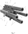
- the reference numbers used in this application are: 1 - Supressor; 2 - Multi-ejector vacuum generator; 3 - Female electrical connection of the pneumatic solenoid valve, mounted on the body; 5 - Top closing lid; 6 - Quick-release fastening system; 7 - Quick-release fastening system; 9 - Finishing cap for the solenoid valves; 10 - Vacuum pump body; 13 - Air passage control solenoid valves; 14 - Quick-release fastening system; 16 - Internal support for fastening the vacuum inlet flange; 17 - Compressed air inlet flange; 18 - Vacuum inlet flange; 19 - Reinforcement ring for the mesh; 20 - Function plate for compressed air; 21 - Quick-release fastening pin; 22 - Vacuum pump body closing O-ring ; 23 - Sealing O-ring; 25 - Quick-release fastening system; 26 - Quick-release fastening system; 25 - Upper sealing O-ring; 27 - Lower sealing
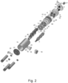
- the present invention discloses a multi-ejector vacuum generator for vacuum generating pump comprising at least three stages 50, 51, 52, and at least four nozzles 62, 63, 64, 65, each stage 50, 51, 52 comprises a vacuum chamber and at least two diaphragms 53 configured to act as one-way valves; each nozzle 62, 63, 64, 65 is configured to act as a receiver at its proximal end and an ejector at its distal end; wherein, the first nozzle 62 is convergent-parallel-divergent, the second nozzle 63 is parallel, the third nozzle 64 is parallel-divergent and the fourth nozzle 65 is parallel-divergent; wherein, the distal end of the first nozzle 62 is connected to the vacuum chamber of the first stage 50 in its proximal portion; the proximal end of the second nozzle 63 is connected to the first stage 50 vacuum chamber in its distal portion; the distal end of the second nozzle 63 is connected to the second stage
- each nozzle 62, 63, 64, 65 is a receiver while the distal end is an ejector.
- Nozzles 62, 63, 64, 65 are positioned internally to stages 50, 51, 52, configured longitudinally, and diaphragms 53 are positioned on the external surfaces of stages 50, 51, 52, orthogonally to nozzles 62, 63, 64 , 65.
- Diaphragms 53 are valves that control the air output in the vacuum chambers.
- the number of diaphragms 53 configured to act as one-way valves depends on the amount of air consumed by the multi-ejector vacuum generator.
- Nozzles 62, 63, 64, 65, stages 50, 51, 52 and feed sleeve 54 are coaxial.
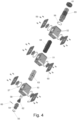
- Diaphragms 53 are connected to each stage 50, 51, 52 so that between the surface of the stage and the diaphragm 53 there is a sealing ring, or o-ring 57.
- a plate 60 is positioned so that the diaphragm 53 is between said plate 60 and the stage 50, 51, 52, in order to enable its operation as a valve, regulating the pressure between the interior of the multi-ejector vacuum generator and the external medium.
- Diaphragms 53 are configured to allow air to enter the stages when the outside pressure is greater than the inside pressure.
- the plate 60 is fixed to the stage 50, 51, 52 by means of polymeric glue, screws, adhesives or polymeric or metallic weld.
- a feed sleeve 54 is configured to connect the compressed air inlet with the first nozzle 62.
- Said feed sleeve 54 has a parallel shape with an internal diameter preferably between 10 and 110 mm, more preferably between 12 and 100 mm, and a length preferably between 20 and 250 mm, more preferably between 18 and 245 mm.
- Feed sleeve 54 connects to first nozzle 62 by thread, snap rings, under pressure or interference.
- the first nozzle 62 has, in its parallel portion, a diameter preferably between 3 and 60 mm, more preferably between 4 and 56 mm, even more preferably between 4.24 and 54.38 mm and, in its divergent portion, an angle of divergence preferably between 7 and 9 degrees, more preferably between 7.5 and 8.5 degrees, even more preferably between 7.9 and 8.3 degrees, and maximum diameter preferably between 5 and 95 mm, more preferably between 6 and 90 mm, even more preferably between 6.93 and 88.82 mm.
- the second nozzle 63 has an internal diameter preferably between 10 and 160 mm, more preferably between 11 and 155 mm, even more preferably between 11.73 and 150.45 mm.
- the third nozzle 64 has in its parallel portion, diameter preferably between 15 and 210 mm, even more preferably between 15.5 and 205 mm, even more preferably between 15.83 and 203.01 mm and in its divergent portion, maximum diameter preferably between 17 and 240 mm, more preferably between 18 and 236 mm, even more preferably between 18.32 and 234.91, and angle of divergence preferably between 0.5 and 3.5 degrees, more preferably between 1 and 3 degrees, furthermore more preferably between 1.5 and 2.5 degrees.
- the fourth nozzle 65 has in its parallel portion, diameter preferably between 22 and 295 mm, more preferably between 22.5 and 293 mm, even more preferably between 22.81 and 292.54 mm and in its divergent portion, maximum diameter preferably between 25 and 330 mm, more preferably between 25.50 and 327.06 mm, and angle of divergence preferably between 1 and 5 degrees, even more preferably between 1.5 and 3 degrees.
- the distance between the distal surface of the first nozzle 62 and the proximal surface of the second nozzle 63 is preferably between 2 and 40 mm, more preferably between 2.5 and 38.5 mm, even more preferably between 2.93 and 37.61 mm, the distance between the distal surface of the second nozzle 63 and the proximal surface of the third nozzle 64 is preferably between 2 and 55 mm, more preferably 3 and 53 mm, even more preferably between 3.96 and 50.75 mm and the distance between the distal surface of the third nozzle 64 and the proximal surface of the fourth nozzle 65 is preferably between 4 and 80 mm, more preferably between 5 and 75 mm, even more preferably between 5.70 and 73.14 mm.
- Stages 50, 51, 52 and nozzles 62, 63, 64, 65 are connected by thread, snap rings, under pressure or interference.
- Said stages 50, 51, 52 are made of metallic or polymeric material, preferably aluminum, 6351 T6 or 7075. In a preferred configuration, they are all of the same material. In alternative configurations, they can be of different materials.
- Said nozzles 62, 63, 64, 65 and the feed sleeve 54 are made of metallic or polymeric material, preferably aluminum, 6351T6 or 7075. In a preferred configuration, they are all of the same material. In alternative configurations, they can be of different materials.
- the sizing of the components of said pump comprises the following steps:
- Air consumption is defined by the desired free vacuum flow. Air consumption is measured in Nl/min (Normal liters/minute), that is, it is a standardized measure, considering 20 °C (68 °F) and 1.01325 bar (14.69595 PSI). The present invention has a coefficient of 4.5 to 5.5 times the standard condition.
- the present invention has fastening means for a multi-ejector vacuum generator 2 for a vacuum generator pump 100 comprising quick-release fastening system 7, 31, 6 having different openings configured so that when the feeding pressure inlets, provided with quick-release fastening pins 21, go beyond the quick-release fastening system 7, 31, 6 and are rotated to the position defined in the second quick-release fastening system 31, the quick-release fastening system 31 does not allow its rotational movement, and the quick-release fastening system 7 does not allow its translational movement in the direction it entered.
- the quick-release fastening system are arranged so that the quick-release fastening means has a first quick-release fastening system 7, a second quick-release fastening system 31 and a third quick-release fastening system 6.
- the feeding pressure ports pass through the first quick-release fastening system 7, then the second quick-release fastening system 31 and then the third quick quick-release fastening 6.
- the multi-ejector vacuum generator 2 is inserted into the fastening means made up of the system 7, 31, 6.
- the position of the multi-ejector vacuum generator 2 is guided by the quick-release fastening pins 21 together with the opening of the quick-release fastening system 7.
- the quick-release fastening system 7 In the same position defined by the quick-release fastening system 7, it is inserted into the quick-release fastening system 31 and 6.
- the multi-ejector vacuum generator 2 is rotated, so that the pins the quick-release fastening pins 21 are locked by opening the quick-release fastening system 6.
- the multi-ejector vacuum generator 2 is then returned into a position where the quick-release fastening pins 21 are limited by the opening in the quick-release fastening system 31.
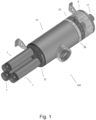
- the present invention also discloses a vacuum generator pump 100 comprising at least a suppressor 1, a vacuum pump body 10, a lower closing cap 37, multi-ejector vacuum generator 2 fastening means, O-ring vacuum pump body closing 22, compressed air passage plate 38, function plate for compressed air 20, air passage control solenoid valves 13, finishing cap for solenoid valves 9, top closing lid 5, pressure gauge 33, vacuum gauge 42, compressed air inlet flange 17.
- Suppressor 1 is coaxial with multi-ejector vacuum generator 2 and consequently coaxial with nozzles 62, 63, 64, 65, stages 50, 51, 52 and feed sleeve 54.
- the vacuum pump body 10 comprises an internal support for fastening the vacuum inlet flange 16, vacuum inlet flange 18, reinforcement ring for the mesh 19, steel mesh at the vacuum inlet 40 and O-ring 43. Said flanges and steel mesh allow a brief air filtration so that the air exchange can be carried out according to the configuration of the diaphragms 53 that act as valves.
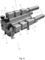
- the multi-ejector vacuum generators 2 are positioned internally to the vacuum pump body 10.
- the multi-ejector vacuum generators 2 are fixed by fastening means at its upper end and, at its upper end bottom, by the lower closing lid 37 together with ejector fastening nuts 34.
- the multi-ejector vacuum generator 2 is external to the vacuum pump body 10'.
- the multi-ejector vacuum generator 2 is connected to the suppressors 1. At its upper end, the multi-ejector vacuum generator 2 is connected with the vacuum pump body closing o-ring 22, compressed air passage plate 38, function plate for compressed air 20, air passage control solenoid valves 13, finishing cap for the solenoid valves 9, as well as pressure gauge 33 and vacuum gauge 42, in addition to the compressed air inlet flange 17.
- the compressed air after passing through the compressed air inlet flange 17, passes through the pressure gauge 33 and vacuum gauge 42 in the manifold 67, and then is submitted to the air passage control solenoid valves 13.
- the air passage control solenoid valves 13 are present.
- the manifold 67 works as a pre-chamber, which receives the compressed air and normalizes its pressure, in addition to distributing the air to each multi-ejector vacuum generator 2.
- the pressure in the pre-chamber is preferably between 4 and 7 bar, more preferably between 5 and 6 bar, even more preferably 5.5 bar.
- the air passage control solenoid valves 13 make it possible to activate or deactivate the pump, just like an on/off switch.
- the air passage control solenoid valves 13 allow the regulation of the compressed air flow, defining a greater or lesser vacuum.
- the compressed air After passing through the air passage control solenoid valves 13, the compressed air passes through the compressed air passage plate 38 and the function plate for compressed air 20, in order to be distributed to each of the multi-ejector vacuum generators 2.
- Each vacuum generating pump 100 can comprise one or more multi-ejector vacuum generators 2, connected in series or parallel, depending on the required vacuum.
- the present invention fulfills the proposed objective, namely a vacuum generator pump 100 with considerably higher efficiency than the vacuum pumps on the market, in particular, to multi-ejector vacuum pumps.
- Table 1 shows different embodiments of multi-ejectors from different brands, for a vacuum level of -90 kPa. It should be noted that, for the same vacuum level, some pumps need 1320 to 1680 Nl/min, while the present invention (called Franco) is capable of achieving the same vacuum level and equal or greater vacuum flow with only 876 Nl/min.
- Table 2 reveals other multi-ejector configurations, for a vacuum level of - 90 kPa. Note that, for the same vacuum level, some pumps need 1680 to 1920 Nl/min, while the present invention is capable of achieving the same vacuum level, or even more vacuum with the same vacuum flow or higher, with only 944 Nl/min.
- Table 3 reveals a comparison between different models from different brands based on their efficiency. Efficiency was obtained by integrating the consumption curves by vacuum level. Table 3- Comparison of multi-ejectors by efficiency Brand Model Efficiency (%) Piab Pi 15 Piab Xi 18 Piab Si 22 Max MLL 400 18 Round Si 23 Franco Master 29.7 Franco Hib 34.6
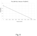
- the generated vacuum curve (kPa (N/m 2 )) as a function of air flow (Nm 3 /s) is not linear, and figure 8 and equation 1 are only an illustrative model.
- a normalized consumption of 128 Nl/min normal liters per minute is equivalent to 1 hp or 745.7 Watts.
Landscapes
- Engineering & Computer Science (AREA)
- Physics & Mathematics (AREA)
- Fluid Mechanics (AREA)
- Mechanical Engineering (AREA)
- General Engineering & Computer Science (AREA)
- Jet Pumps And Other Pumps (AREA)
- Reciprocating Pumps (AREA)
Applications Claiming Priority (1)
| Application Number | Priority Date | Filing Date | Title |
|---|---|---|---|
| BR102022026102-4A BR102022026102A2 (pt) | 2022-12-20 | Gerador de vácuo multi-ejetor, meio de fixação de gerador de vácuo multi-ejetor e bomba geradora de vácuo |
Publications (3)
| Publication Number | Publication Date |
|---|---|
| EP4400729A2 true EP4400729A2 (de) | 2024-07-17 |
| EP4400729A3 EP4400729A3 (de) | 2024-09-11 |
| EP4400729B1 EP4400729B1 (de) | 2026-02-04 |
Family
ID=89121820
Family Applications (1)
| Application Number | Title | Priority Date | Filing Date |
|---|---|---|---|
| EP23214906.2A Active EP4400729B1 (de) | 2022-12-20 | 2023-12-07 | Vakuumerzeuger mit mehreren saugdüsen, befestigungsmittel-vakuumerzeuger mit mehreren saugdüsen und vakuumerzeugerpumpe |
Country Status (2)
| Country | Link |
|---|---|
| US (1) | US20240200578A1 (de) |
| EP (1) | EP4400729B1 (de) |
Citations (3)
| Publication number | Priority date | Publication date | Assignee | Title |
|---|---|---|---|---|
| BRPI0501916A (pt) | 2005-05-17 | 2007-01-16 | Luiz Tadeu Sel Franco | aperfeiçoamentos introduzidos em bomba de vácuo a ar comprimido |
| US10400796B2 (en) | 2014-04-24 | 2019-09-03 | Vmeca Co., Ltd. | Ejector assembly and vacuum pump |
| US10767662B2 (en) | 2012-12-21 | 2020-09-08 | Piab Aktiebolag | Multi-stage vacuum ejector with molded nozzle having integral valve elements |
Family Cites Families (23)
| Publication number | Priority date | Publication date | Assignee | Title |
|---|---|---|---|---|
| US2378425A (en) * | 1938-02-22 | 1945-06-19 | Murray Henry Lamont | Ejector-condenser |
| SE370765B (de) * | 1973-12-05 | 1974-10-28 | Piab Ab | |
| SE427955B (sv) * | 1980-05-21 | 1983-05-24 | Piab Ab | Multiejektor |
| US4609328A (en) * | 1980-06-18 | 1986-09-02 | Ctp Partners | Method and apparatus for total energy systems |
| DE3025525A1 (de) * | 1980-07-05 | 1982-01-28 | Jürgen 4477 Welver Volkmann | Ejektorvorrichtung |
| IL74282A0 (en) * | 1985-02-08 | 1985-05-31 | Dan Greenberg | Multishaft jet suction device |
| US4790054A (en) * | 1985-07-12 | 1988-12-13 | Nichols William O | Multi-stage venturi ejector and method of manufacture thereof |
| GB8716626D0 (en) * | 1987-07-15 | 1987-08-19 | Permutit Co Ltd | Mixing liquids |
| US4880358A (en) * | 1988-06-20 | 1989-11-14 | Air-Vac Engineering Company, Inc. | Ultra-high vacuum force, low air consumption pumps |
| SE469291B (sv) * | 1991-10-31 | 1993-06-14 | Piab Ab | Ejektorarrangemang innefattande minst tvaa tryckluftsdrivna ejektorer samt foerfarande foer att med minst tvaa tryckluftsdrivna ejektorer aastadkomma ett oenskat undertryck paa kortast moejliga tid och med minsta energifoerbrukning |
| JP3421701B2 (ja) * | 1993-03-31 | 2003-06-30 | Smc株式会社 | 多段エゼクタ装置 |
| SE511716E5 (sv) * | 1998-03-20 | 2009-01-28 | Piab Ab | Ejektorpump |
| IL125791A (en) * | 1998-08-13 | 2004-05-12 | Dan Greenberg | Vacuum pump |
| US6976645B2 (en) * | 2003-07-30 | 2005-12-20 | Kabushiki Kaisha Hitachi Seisakusho | Ejector for use with pneumatic booster |
| KR100578540B1 (ko) * | 2004-07-28 | 2006-05-15 | 한국뉴매틱(주) | 진공 이젝터 펌프 |
| KR100629994B1 (ko) * | 2005-12-30 | 2006-10-02 | 한국뉴매틱(주) | 진공 이젝터 펌프 |
| KR100993678B1 (ko) * | 2007-12-13 | 2010-11-10 | 현대자동차주식회사 | 연료전지시스템의 다단 직렬 카트리지 이젝터 장치 |
| IL215426A (en) * | 2011-09-27 | 2017-10-31 | Dan Geva | Complex vacuum pump |
| GB2509183A (en) * | 2012-12-21 | 2014-06-25 | Xerex Ab | Vacuum ejector with tripped diverging exit flow nozzle |
| DE102013107537B4 (de) * | 2013-07-16 | 2015-02-19 | J. Schmalz Gmbh | Mehrstufiger Ejektor |
| SE539775C2 (sv) * | 2014-06-23 | 2017-11-28 | Onishi Teknik Ab | Flerstegs vakuumejektor |
| KR101685998B1 (ko) * | 2016-09-21 | 2016-12-13 | (주)브이텍 | 프로파일을 이용한 진공 펌프 |
| US20230304510A1 (en) * | 2022-03-25 | 2023-09-28 | Guardair Corp. | Multistage vacuum |
-
2023
- 2023-12-07 EP EP23214906.2A patent/EP4400729B1/de active Active
- 2023-12-11 US US18/535,679 patent/US20240200578A1/en active Pending
Patent Citations (3)
| Publication number | Priority date | Publication date | Assignee | Title |
|---|---|---|---|---|
| BRPI0501916A (pt) | 2005-05-17 | 2007-01-16 | Luiz Tadeu Sel Franco | aperfeiçoamentos introduzidos em bomba de vácuo a ar comprimido |
| US10767662B2 (en) | 2012-12-21 | 2020-09-08 | Piab Aktiebolag | Multi-stage vacuum ejector with molded nozzle having integral valve elements |
| US10400796B2 (en) | 2014-04-24 | 2019-09-03 | Vmeca Co., Ltd. | Ejector assembly and vacuum pump |
Also Published As
| Publication number | Publication date |
|---|---|
| EP4400729A3 (de) | 2024-09-11 |
| US20240200578A1 (en) | 2024-06-20 |
| EP4400729B1 (de) | 2026-02-04 |
Similar Documents
| Publication | Publication Date | Title |
|---|---|---|
| US5931643A (en) | Fluid jet ejector with primary fluid recirculation means | |
| JP5804533B2 (ja) | チューブレスタイヤ着座装置 | |
| JP2925331B2 (ja) | 極低温粒子ブラストシステム用ノズル | |
| CN105264238B (zh) | 具有带一体阀元件的模制管嘴的多级真空喷射器 | |
| CN105051376B (zh) | 具有多喷嘴驱动级段和增强器的真空喷射器 | |
| JP4902062B2 (ja) | 改良型空気式スプレーノズル | |
| CN104870830B (zh) | 具有脱扣的发散出口流动管嘴的真空喷射器 | |
| US8752604B2 (en) | Jet assisted tubeless tire seating device | |
| US6997405B2 (en) | External mix air atomizing spray nozzle assembly | |
| TW213436B (de) | ||
| EP4400729A2 (de) | Vakuumerzeuger mit mehreren saugdüsen, befestigungsmittel-vakuumerzeuger mit mehreren saugdüsen und vakuumerzeugerpumpe | |
| CN105026772B (zh) | 具有椭圆发散部分的真空喷射器管嘴 | |
| US8006961B1 (en) | Apparatus and method for treating process fluid | |
| US5799875A (en) | HVLP spray gun and integrated fluid nozzle therefor | |
| CN111288028B (zh) | 一种应用于火星风洞的低气压引射器装置 | |
| EP3163093B1 (de) | Hochvakuumejektor | |
| US20040047749A1 (en) | Double diaphragm pump having a spool valve | |
| CN112705369A (zh) | 一种自动调节吸气速度的扇形气吸喷头 | |
| CN109538798B (zh) | 一种减压阀 | |
| US6171068B1 (en) | Vacuum pump | |
| CN210875853U (zh) | 一种气动雾化和气泡雾化相结合的喷嘴 | |
| US20230304510A1 (en) | Multistage vacuum | |
| BR102022026102A2 (pt) | Gerador de vácuo multi-ejetor, meio de fixação de gerador de vácuo multi-ejetor e bomba geradora de vácuo | |
| EP0054525B1 (de) | Strahlpumpen-Einrichtung | |
| GB1179433A (en) | Apparatus for producing Short Duration Blasts of High Pressure Gaseous Fluid from the Discharge Outlet of a Valve Connected to a High Pressure Supply Line |
Legal Events
| Date | Code | Title | Description |
|---|---|---|---|
| PUAI | Public reference made under article 153(3) epc to a published international application that has entered the european phase |
Free format text: ORIGINAL CODE: 0009012 |
|
| STAA | Information on the status of an ep patent application or granted ep patent |
Free format text: STATUS: THE APPLICATION HAS BEEN PUBLISHED |
|
| AK | Designated contracting states |
Kind code of ref document: A2 Designated state(s): AL AT BE BG CH CY CZ DE DK EE ES FI FR GB GR HR HU IE IS IT LI LT LU LV MC ME MK MT NL NO PL PT RO RS SE SI SK SM TR |
|
| PUAL | Search report despatched |
Free format text: ORIGINAL CODE: 0009013 |
|
| AK | Designated contracting states |
Kind code of ref document: A3 Designated state(s): AL AT BE BG CH CY CZ DE DK EE ES FI FR GB GR HR HU IE IS IT LI LT LU LV MC ME MK MT NL NO PL PT RO RS SE SI SK SM TR |
|
| RIC1 | Information provided on ipc code assigned before grant |
Ipc: F04F 5/46 20060101ALI20240806BHEP Ipc: F04F 5/22 20060101ALI20240806BHEP Ipc: F04F 5/16 20060101AFI20240806BHEP |
|
| STAA | Information on the status of an ep patent application or granted ep patent |
Free format text: STATUS: REQUEST FOR EXAMINATION WAS MADE |
|
| 17P | Request for examination filed |
Effective date: 20250211 |
|
| GRAP | Despatch of communication of intention to grant a patent |
Free format text: ORIGINAL CODE: EPIDOSNIGR1 |
|
| STAA | Information on the status of an ep patent application or granted ep patent |
Free format text: STATUS: GRANT OF PATENT IS INTENDED |
|
| INTG | Intention to grant announced |
Effective date: 20251009 |
|
| GRAS | Grant fee paid |
Free format text: ORIGINAL CODE: EPIDOSNIGR3 |
|
| GRAA | (expected) grant |
Free format text: ORIGINAL CODE: 0009210 |
|
| STAA | Information on the status of an ep patent application or granted ep patent |
Free format text: STATUS: THE PATENT HAS BEEN GRANTED |
|
| AK | Designated contracting states |
Kind code of ref document: B1 Designated state(s): AL AT BE BG CH CY CZ DE DK EE ES FI FR GB GR HR HU IE IS IT LI LT LU LV MC ME MK MT NL NO PL PT RO RS SE SI SK SM TR |
|
| REG | Reference to a national code |
Ref country code: CH Ref legal event code: F10 Free format text: ST27 STATUS EVENT CODE: U-0-0-F10-F00 (AS PROVIDED BY THE NATIONAL OFFICE) Effective date: 20260204 Ref country code: GB Ref legal event code: FG4D |